

Page 1

Operator’s Manual
4501 Parkway Commerce Blvd.
Asia-Pacific
19 Loyang Way
#01-01 CILC Building
Singapore 508724
Phone: +65 542-2611
Fax: +65 542-3611
Corporate Headquarters
Orlando, Fl 328 08
Phone: 407-578-8007
Fax: 407-5 78-8377
12 Elizabeth Way, Pinnacles
Harlow, Esse x CM19 5FE UK
Datamax International
Herbert House
Phone : +44 127 9 772200
Fax: +44 1279 424448
Page 2

Page 3

Copyright Information:
CG Triumvirate is a trademark of Agfa Corporation.
CG Times based upon Times New Roman under license from the Monotype
Corporation.
Windows is a registered trademark of the Microsoft Corporation.
All other brand and product names are trademarks, service marks, registered
trademarks, or registered service marks of their respective companies.
Firmware (Software) Agreement
The enclosed Firmware (Software) resident in the Printer is owned by Licensor or
its suppliers and is licensed for used only on a single printer in the user’s Trade
or Business. The User agrees not to, and not to authorize or permit any
other person or party to, duplicate or copy the Firmware or the
information contained in the non-volatile or programmable memory. The
firmware (Software) is protected by applicable copyright laws and Licensor
retains all rights not expressly granted. In no event will Licensor or its suppliers
be liable for any damages or loss, including direct, incidental, economic, special,
or consequential damages, arising out of the use or inability to use the Firmware
(Software).
Information in this document is subject to change without notice and does not
represent a commitment on the part of Datamax Barcode Products Corporation.
No part of this manual may be reproduced or transmitted in any form or by any
means, for any purpose other than the purchaser's personal use, without the
expressed written permission of Datamax Corporation.
All rights reserved. Printed in the United States of America.
© Copyright 2008 by Datamax Corporation
Part Number: 88-2304-01
Revision: D
Page 4
Agency Compliance and Approvals:
C US
Listed
FCC: This device complies with FCC CFR 47 Part 15 Cl ass A.
; Note: This equipment has been tested and found to comply with the limits for a Class A
UL1950 Information Technology Equipment
C22.2 No. 950-M93
EN60950
For 230 Volt Operation (Europe): Use a cord set, marked "HAR," consisting of a
min H05VV-F cord which has a minimum 0.75 square mm diameter conductors,
provided with an IEC 320 receptacle and a male plug for the country of installation
rated 6A, 250V
Für 230 Volt (Europa): Benützen Sie ein Kabel, das mit "HAR" markiert ist,
bestehend mindestens aus einem H05VV-F Kabel, das mindestens 0,75
Q u a d r at millime t er D r a h t d u r c h me s s er h a t ; s ow ie eine I E C 320 Steckdose und einen
für das Land geeigneten Stecker, 6A, 250 Volt.
As an Energy Star Partner, the manufacturer has determined that this product meets
the Energy Star guidelines for energy efficiency.
The manufacturer declares under sole responsibility that this product conforms to the
following standards or other normative documents:
EMC: EN 55022 (1993) Class A
EN 50024 (1998)
Safety: This product complies with the requirements of EN 60950 /A11:1997
Gost-R
digital device, pursuant to Part 15 of the FCC Rules. These limits are designed to
provide reasonable protection against harmful interference when the equipment is
operated in a commercial environment. This equipment generates, uses, and can
radiate radio frequency energy, and if not installed and used in accordance with
the instructions in this manual, it may cause harmful interference to radio
communications. Operation of this equipment in a residential area is likely to
cause harmful interference in which case the user will be required to correct the
inter f er ence at his own expen se.
Page 5

Important Safety Instructions
This printer has been carefully designed to provide many years of safe,
reliable performance. As with all electrical equipment, there are a few
basic precautions you should take to avoid hurting yourself or damaging
the printer:
• Carefully rea d the installation and operating instructions provided
with your printer.
• Read and follow all warning instruction labels on the printer.
• Place the printer on a flat, firm, solid surface.
• To protect your printer from overheating, make sure all openings on
the printer are not blocked.
• Do not place the printer on or near a heat source.
• Do not use your printer near water, or spill liquid into it.
• Be certain that your power source matches the rating listed on your
printer. If you are unsure, check with your dealer or with your local
power company.
• Do not place the power cord where it will be walked on. If the power
cord becomes damaged or frayed replace it immediately.
• Do not insert anything into the ventilation slots or openings on the
printer.
• Only qualified, trained s ervic e tec hnicians should attempt to repair
your printer.
Page 6

Page 7

Printer Overview
1.0 Introduction .....................................................................1
1.1 About this Prin te r.............................................................2
1.1.1 Standard Features................................................2
1.1.2 Optional Features.................................................3
Getting Started
2.0 Before using the Printer..................................................5
Setting Up the Printer
3.0 Introduction .....................................................................7
3.1 Connecting the Printer.....................................................7
3.1.1 Power Connection................................................7
3.1.2 Interface Connection ............................................8
3.1.3 Interface Cables ...................................................8
3.2 Adjusting the Media Sensor............................................9
3.3 Loading Media ................................................................12
3.3.1 Loading Media for Peel Configuration..................14
3.4 Loading Ribbon...............................................................15
3.5 Flash Memory Expansion................................................17
Using the Front Panel
4.0 Introduction .....................................................................19
4.1 Lights...............................................................................19
i
Page 8

4.2 Buttons............................................................................20
4.3 Normal Mode - Button Functions....................................20
4.4 Printer Setup Mode - Bu tton Functions...........................21
4.4.1 Printer Setup Menu List........................................22
4.4.2 Menu Items and Values........................................23
4.4.3 Step by Step Modification....................................26
4.5 Label Alignment...............................................................28
4.5.1 Label Alignment = YES.........................................28
4.5.2 Label Alignment = AUTO......................................29
4.5.3 Label Alignment = NO...........................................29
4.5.4 Label Alignment Troubleshooting.........................30
4.6 Calibration Mode – Button Fun ctions..............................34
4.6.1 Auto Media Sensor Calibration............................35
4.6.2 Manual Media Sensor Calibration ........................36
4.7 Internal Labels.................................................................37
4.7.1 Database Configuration/Dot Check Labels..........37
4.7.2 Test Label.............................................................39
4.7.3 Hex Dum p Label...................................................39
Mai ntenance and Adjustments
5.0 Introduction .....................................................................41
5.1 Cleaning the Printhead....................................................42
5.2 Media Width Adjustment.................................................43
5.3 Ribbon Width Adjustment................................................44
5.4 Fine Printhead Adjustment ..............................................46
5.5 Printhead Replacement...................................................47
5.6 Darkness Adjustment......................................................48
ii
Page 9

5.7 Resetting to the Factory Defaults....................................48
5.8 Downloading Firmw are and Fonts...................................48
Troubleshooting
6.0 In troduction......................................................................51
6.1 Troubleshooting Tips.......................................................51
Specifications
Mechanical..............................................................................55
Printing....................................................................................55
Media/Ribbon.........................................................................56
Communications.....................................................................56
Fonts.......................................................................................56
Embedded Bar Codes............................................................56
Approved Media.....................................................................57
Appendix A
ASCII Control Code Chart......................................................59
Appendix B
Embedded Fonts and Barcodes.............................................61
Appendix C
Warranty Information..............................................................71
Glossary.......................................................................................75
iii
Page 10

iv
Page 11
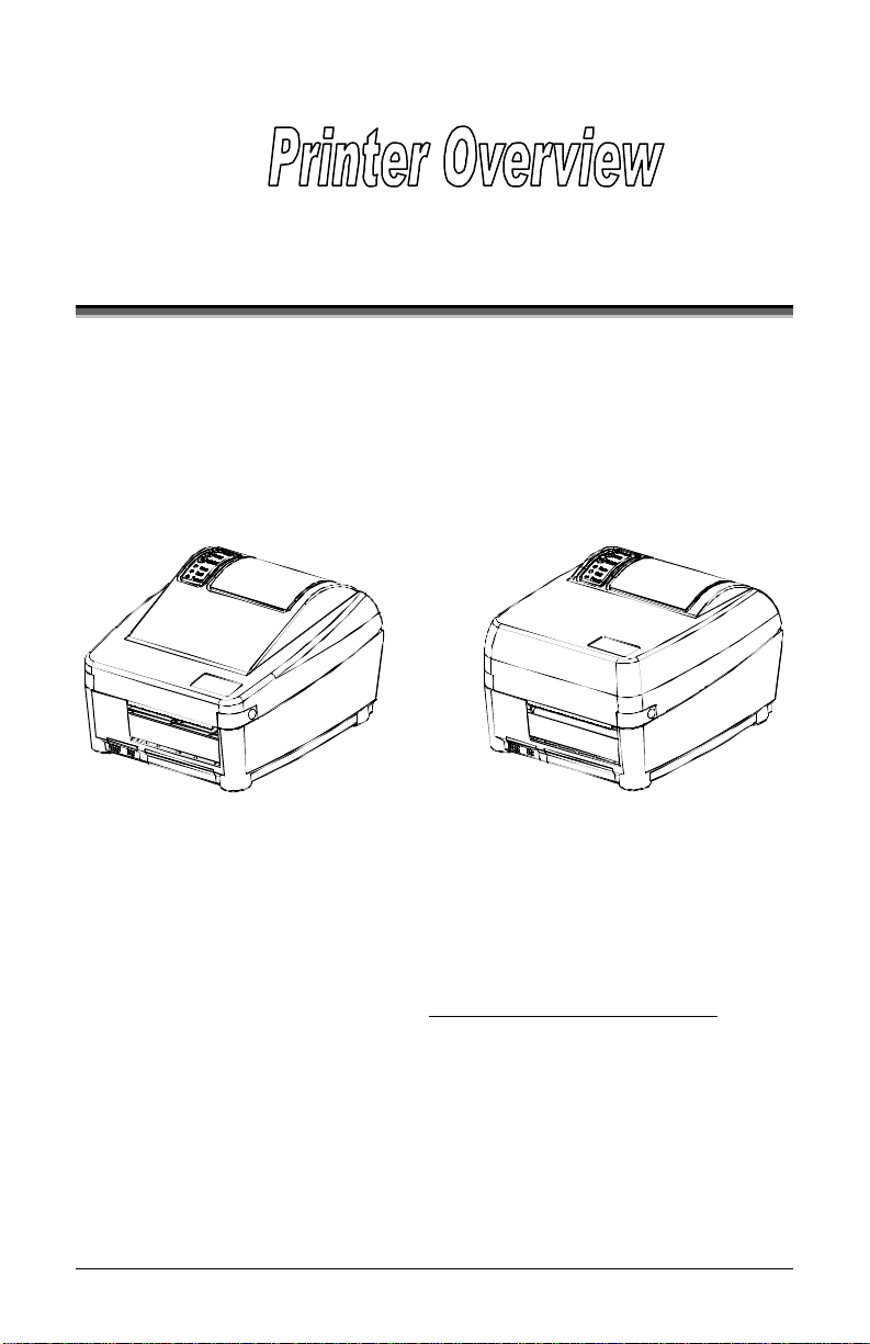
1.0 Introduction
The E-4204 and E-4304 (hereafter referred to as ‘the printer’) are use rfriendly devices that blend quality and durability into an affordable
package. The printer, available in direct and optional thermal transfer
configurations, uses a unique front panel design to simplify operation,
while its RS232 serial, USB, and parallel interfaces allow easy
connection to your host system.
Direct Thermal Model Thermal Transfer Model
This manual provides all the information nece s s a ry to ope rate the printer.
To print labels or ta gs simply refer to the instructions included with the
software you have chosen to create the labels. A Windows™ printer
dr i ve r ca n be f ou nd on our websi t e (ht tp:// www.data maxcorp .com/
the Datamax Accessories CD-ROM.
If you wish to write a custom program, a copy of the Class Series
Programmer ’s Manual (part number 88-2316-01) can also be found on
our website.
) or on
E-Class 1
Page 12

1.1 About this Printer
This printer offers the following sta ndard and optional features:
1.1.1 Standard Features
Printing
¾ Direct T hermal Printing
¾ On De mand and B at ch Printing
¾ 203 or 300 DPI Printhead (model dependent)
¾ AGFA S ca la ble F ont E ngine
Memory
¾ 1 MB FLASH Me mory
¾ 2 MB DRAM Memory
Interfaces
¾ RS-232 serial interface
¾ Centronics
®
parallel interface
¾ USB P ort
Operational
¾ Simple Media Loading
¾ Media Tearbar
¾ Fan-fold media compatible from rear of printer
¾ 1inch (25mm) internal media supply core
2 E-Class
Page 13

1.1.2 Optional Features
Adjustable Media Sensor
The Adjusta ble Media Se nsor allows the printer to detect the position
of the gap, notch, or reflective mark at many locations across the
media.
External Media Supply Stand
The External Media Supply Stand allows the printer to use large
media supply rolls, up to 8-inches in diameter and wound on one to
three inch cores. (Not available for the E-4304.)
FLASH Memory Expansion
The FLASH Expansion cartridges are used for permanent storage of
custom fonts, formats and graphics. The FLASH memory cartridges
cannot be used in conjunction with the ILPC option.
ILPC
The International Language Print Capability consisting of one of the
following:
¾ CG-Times (western European) Scalable font
¾ Kanji Gothic B Scalable font
¾ Simplified Chinese GB Scalable font
Media Cutter
The Media Cutter automatically cuts your tag or label media after
printing. This device mounts easily onto the front of the printer and
cuts material with a maximum thickness of .007” (.177 mm).
E-Class 3
Page 14

Light Duty Media Cutter
This rotary-type dev ice a utomatically cuts material with a maximum
thickness of .005” (.127 mm).
Present Sensor
The Present Sensor allows the printer to be configured for “one up”
printing. With the sensor installed, the printer will not print the next
label until the previously printed label has be e n removed from the
printer.
Thermal Transfer
The Thermal Transfer option allows the printer to use ribbon. The
ink/wax from the ribbon transfers to the media to create an image
with exceptional clarity and sca nability.
4 E-Class
Page 15
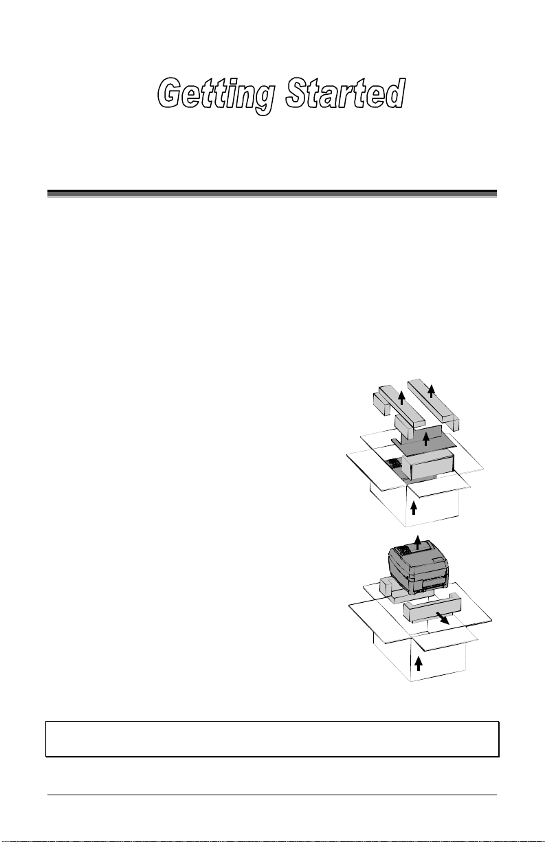
2.0 Before Usi ng th e P rinter
Removi ng the Packaging
Inspect the shipping container(s) for damage; if damage is e vide nt notify
the shipping company to report the nature and extent of the damage.
The printer is carefully packaged to avoid any damage during transit. In
order to operate the printer you will need to remove the packaging
materials (i.e., tape and foam) that were placed in the printer for
shipment. Complete the following steps prior to connecting power or
attempting to load media.
¾ Ensure that the arrow on the box is
pointing up, and then open the box.
¾ Remove the packing foam, cardboard
divider, and power supply box.
¾ Lift the printer from the box and remove
the packing foam.
¾ Remove the printer from the plastic ba g.
;
Note: It is a good idea to save all packaging materials in the event that
shipping the printer is ever required.
E-Class 5
Page 16
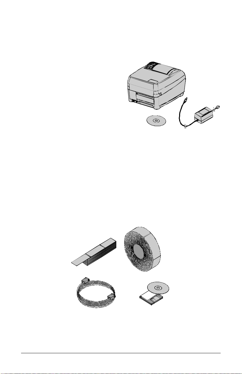
In specting the Printer
After removing the printer from the packaging material, check the
contents. T he following items should be included:
¾ Printer
¾ Power supply
¾ Accessories CD-ROM
¾ Any special or a dditionally
purchased items
Additional Requirements
The following items are neces s ary for generating labels from your printer.
Contact your customer support representative for advice on which media
and software may best be suited for your application.
¾ USB, Serial, or parallel ca ble
¾ Applicable media
¾ Applicable s oftware
6 E-Class
Page 17
3.0 Introduction
This section explains how to connect your printer, load media (and
ribbon, if equipped for thermal transfer), and print a configuration label.
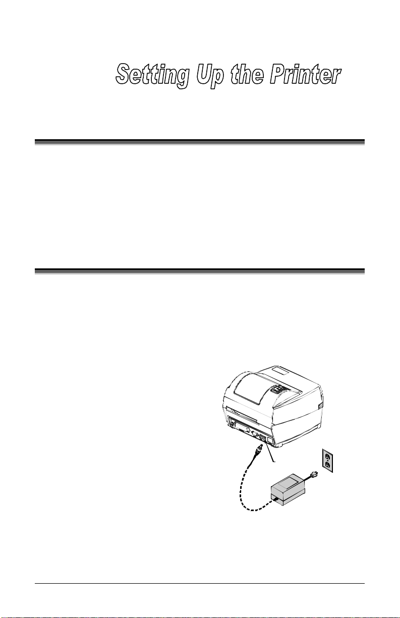
3.1 Connecting t he Prin t er
3.1.1 Power Connection
The printer is powered by an external auto-ranging power supply, which
connects between the printer and wall outlet as shown below.
Before connecting, ensure that
the range of the printer’s power
supply is compatible with your
electrical service (see
Specifications for deta ils ).
Power
Connection
E-Class 7
Page 18
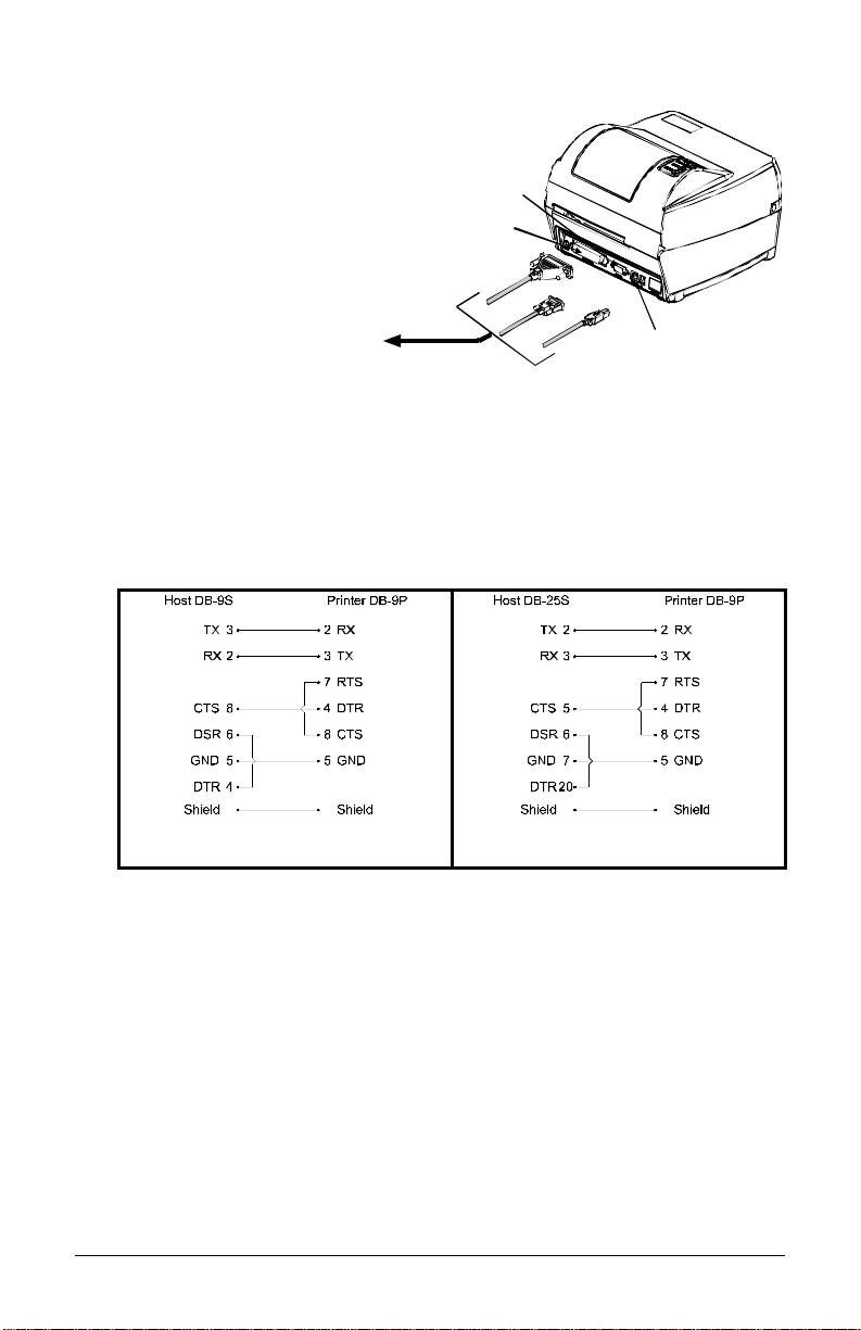
3.1.2 Interface Connection
The printer can be connected to
the host via a USB, serial or
parallel cable.
Serial
Connection
Parallel
Connection
To H os t
-OR-
-OR-
USB
Connection
3.1.3 Interface Cables
Choose a connection method that will best s e rve your purpose:
y To connect the printer to the host’s serial (RS-232C) interface use an
acceptable cable configuration, as shown below (contact your reseller
for orde ring information).
Part # 32-2483-01
Part # 32-2301-01
y To connect the printer to the host’s parallel interface use a
Centronics
®
parallel ca ble .
y To connect the printer to the host’s USB interface use a standard
USB cable.
Note that the printer has a ve rsa tile c ommunications feature: When
connected to more than one interface, the printer will automatically
connect to the first port (se rial, para llel, or USB) from which valid data is
received. After this connection has been made, the printer’s power must
be c yc l e d ‘O ff’ a nd ‘On’ to c hange the interface connection.
8 E-Class
Page 19
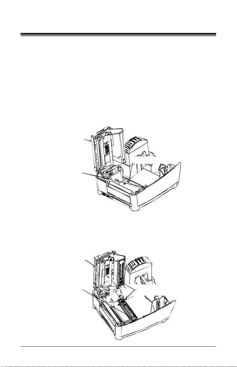
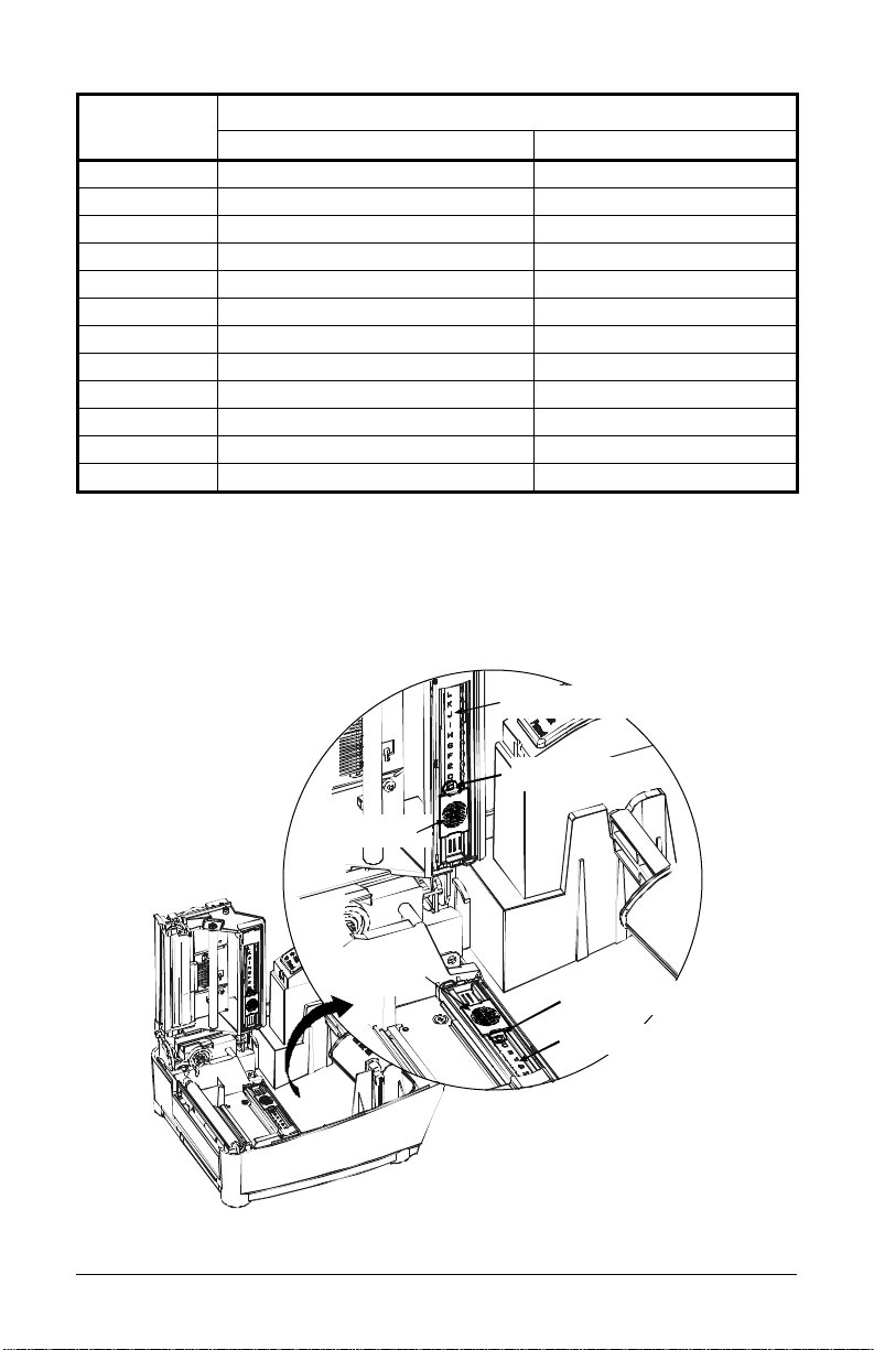
3.2 Adjusting t he Medi a S ensor
The printer is available with a Fixed-Positio n Media Sensor or an
Adjustable Media Sensor. To identify the type of sensor in your printer,
proceed as follows:
1. Ope n the cover.
2. Pus h down the Printhead Latch and raise the Printhead Carrier
Assembly.
The Fixe d-Posi tion Medi a Se nsor, shown below, is immoveable. If your
printer has this sensor, proceed to ‘Loading Media’ (Section 3.3).
Printhead
Carrier Assembly
Fixed-Position Media Sensor
Printhead Latch
The Adjustable Media Sensor (AMS), shown below, may need to be
positioned as described belo w:
Printhead
Carrier Assembly
Printhead Latch
Adjustable Media Sensor
E-Class 9
Page 20
For the proper detection of media and the label top of form (TOF), the
table belo w indicates s uggested AMS positions for various media type s .
Adjustable Media Sensor Position
Media Type Suggested Sensor Placement TOF Sensing Used
Continuous* Near the center of the media Continuous
Die-cut Near the center of the label Gap
Notched Near the center of the notch Gap
Reflective Near the center of the black mark Reflective
*Label TOF for continuous media is set via the Front Panel (CONT FORM LENGT H) or
software; see Section 4.4.2.
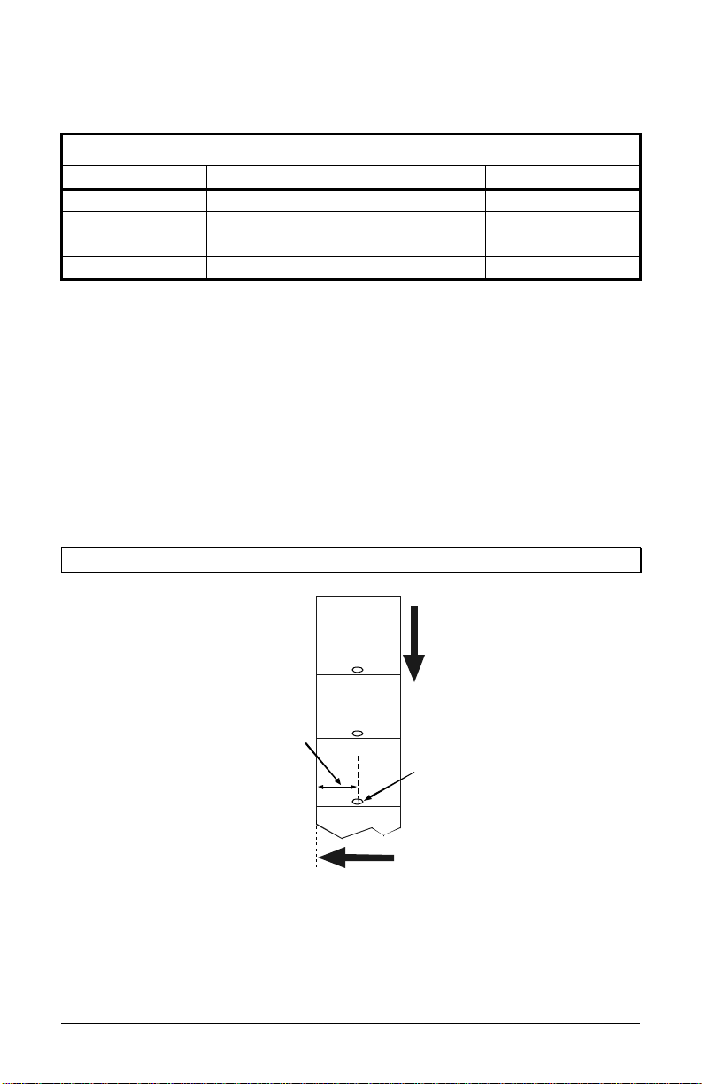
To properly position the AMS, you will need to know where the TOF
mark is located on your media. (For more information on media, see
Specifications.)
Depending of your media type, take a measurement from the left-justified
media edge across to the center of the TOF mark as suggested in the
table above. T he following example illustrates the measurement of
notched media.
;
Note: Reflective marks are placed on the underside of the media.
Media
Movement
Measurement
Notch
Left-Justified
To s implify the adjustment, the AMS uses Reference Letter designators
that correspond to the following TOF mark distances:
10 E-Class
Page 21
Reference
Letter
Distance of the TOF Mark from the Media Edge
(inches) (millimeters)
A .180 4.6
B .500 12.7
C .750 19.1
D 1.00 25.4
E 1.25 31.8
F 1.50 38.1
G 1.75 44.5
H 2.00 50.8
I 2.25 57.2
J 2.50 63.5
K 2.75 69.9
L 3.00 76.2
Position the Adjustable Media Sensor as follows:
1. Based on the measurement made earlier, choose the Reference Letter
that best corresponds to the location of your TOF mark.
Reference Letters
Setting Window
Top Slide
Bottom Slide
Setting Window
Reference Letters
E-Class 11
Page 22
2. Use a finger to move the Bottom Slide until your sele cte d Reference
Letter appears in the Setting Window of the slide .
3. Use a finger to move the Top Slide until your selected Reference
Letter appears in the Setting Window of the slide .
;
Note: The Top and Bottom Slides must be positioned over the same
Reference Letter for proper media sensor function.
4. Proceed to ‘Loading Media’ (Section 3.3).
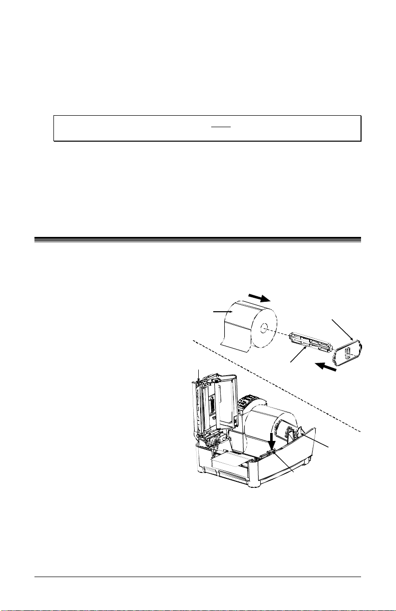
3.3 Loading Media
Load media into the printer as follows:
1. With the Cover open and
the Printhead Carrier
Asse mbly raise d, remove
the Media Hub and insert it
through the Roll Media
(with the labels s pilling
forward).
2. Place the Media Hub Flange
(with its smooth side toward
the media) onto the Media
Hub.
3. Place the Media Hub,
flange, and media onto the
Standoffs in the printer.
4. Route the media through the
printer, as shown below.
Roll
Media
Printhead
Carrier Media
Media Hub Flange
(smooth side toward media)
Hub
Printhead
Latch
Standoff
12 E-Class
Page 23
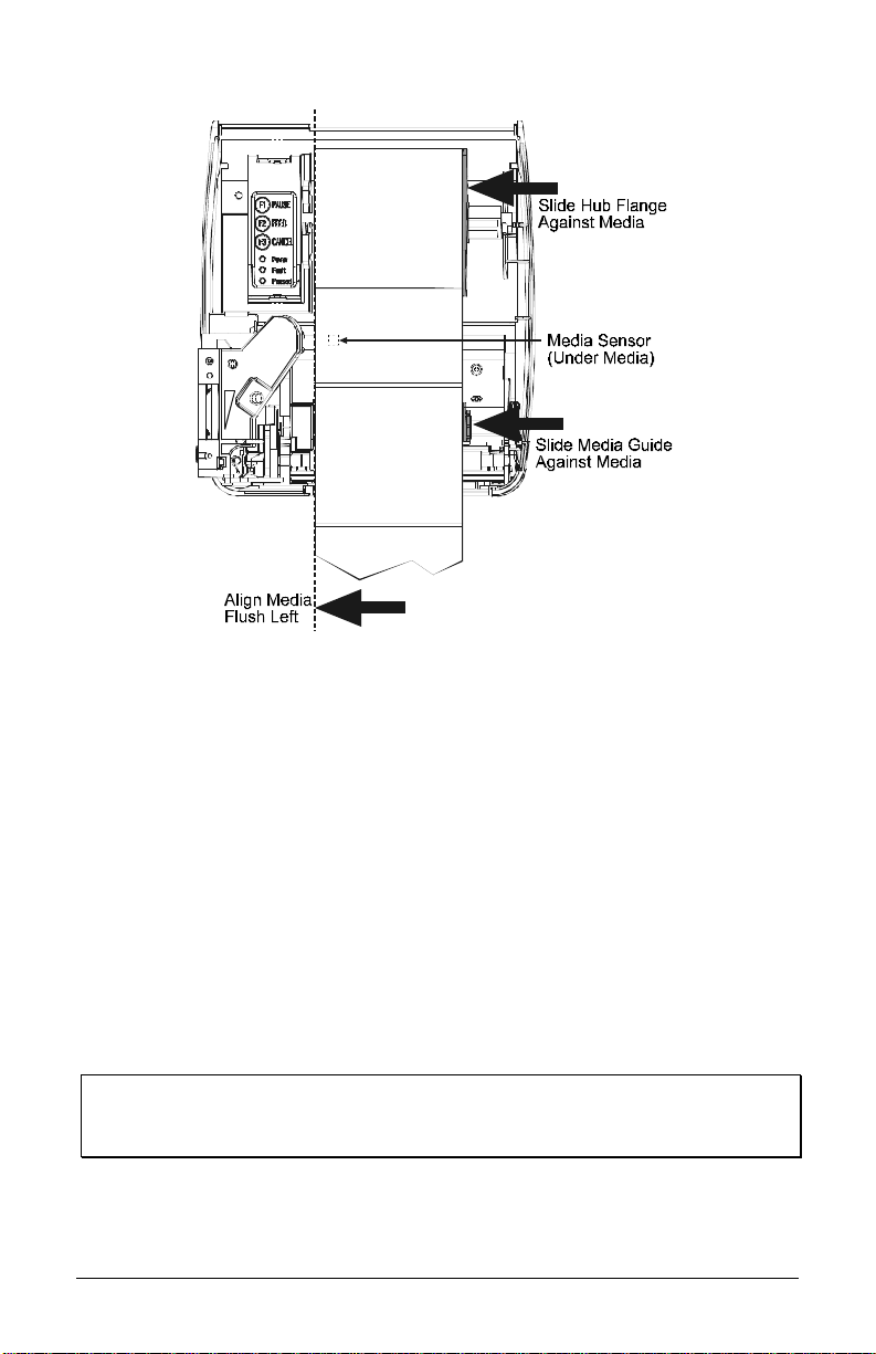
5. Slide the Media Guide and Media Hub Flange to the edge of the
media.
6. C los e the Printhead C arrier As s e mbly and press d own until it locks
into place.
7. C lo s e the cove r and press the Feed button several times to p os ition
the media and ensure proper tracking.
(If the printer does not correctly sense the top of each label, as
denoted by the FAULT Light, it may be necess ary to perform the
Calibration Procedure, Sectio n 4.6. )
;
Note: The printer is factory set to use 4-inch media (and ribbon, if thermal
transfer equipped). When using a different media width, refer to
Section 5 for additional printing adjustments.
E-Class 13
Page 24
3.3.1 Loading Media for Peel Configuration
1. Ope n the cover.
2. Pus h the Printhead Latch down and raise the Printhead Carrier
Assembly.
3. Place a roll of media (labels facing up) on the Media Hub and insert
them into the printer. Slide the Media Hub Flange with its smooth
side towards media onto the Media Hub.
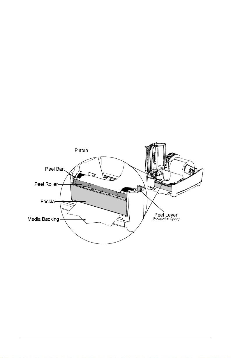
4. Pull the Peel Lever forward to the ‘Open’ position.
5. Remove 6″ (152 mm) of labels from the backing. Route the Media
Backing over the Platen and Peel Bar and behind the Peel Roller and
Fascia as s hown below.
6. Pus h the Peel Lever back to the ‘Close d’ pos ition.
7. C los e the Printhead C arrier As s e mbly and press d own until it locks
into place.
8. Close the cover and press the Feed button several times to advance
the media a nd ensure proper tracking. The labels will sep ara te
automatically as it is fed through the printer. (If the printer does not
correctly sense the top of each label, as denoted by the FAULT Light,
it may be necessa ry to pe rform the Ca libratio n Procedure, Section
4.6.)
14 E-Class
Page 25
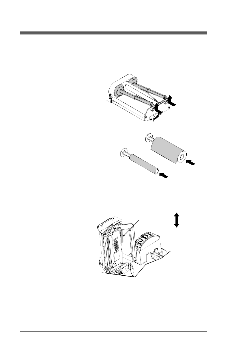
3.4 Loading Ribbon
Ribbon is required with thermal transfer media. If your printer is
equipped with the thermal transfer option and if you will be using thermal
transfer media, load ribbon as follows:
1. Open the cover.
2. Remove both
Ribbon Hubs.
3. Slide a roll of
Ribbon onto one
of the Ribbon
Hubs and an
Empty Core onto
the other hub.
4. Push the
Printhead Latch
down and raise
the Printhead
Carrier
Assembly.
5. Slide the Media
Type Switch into
the ‘Tra nsfe r’
position.
Sli de a Ribbon onto a H ub an d
an Em pty Co re onto a Hub
Empty Core
Push in and lift
to remov e the Hub s
Ribbon
Direct
Me di a Type Switch
Transfer
E-Class 15
Page 26
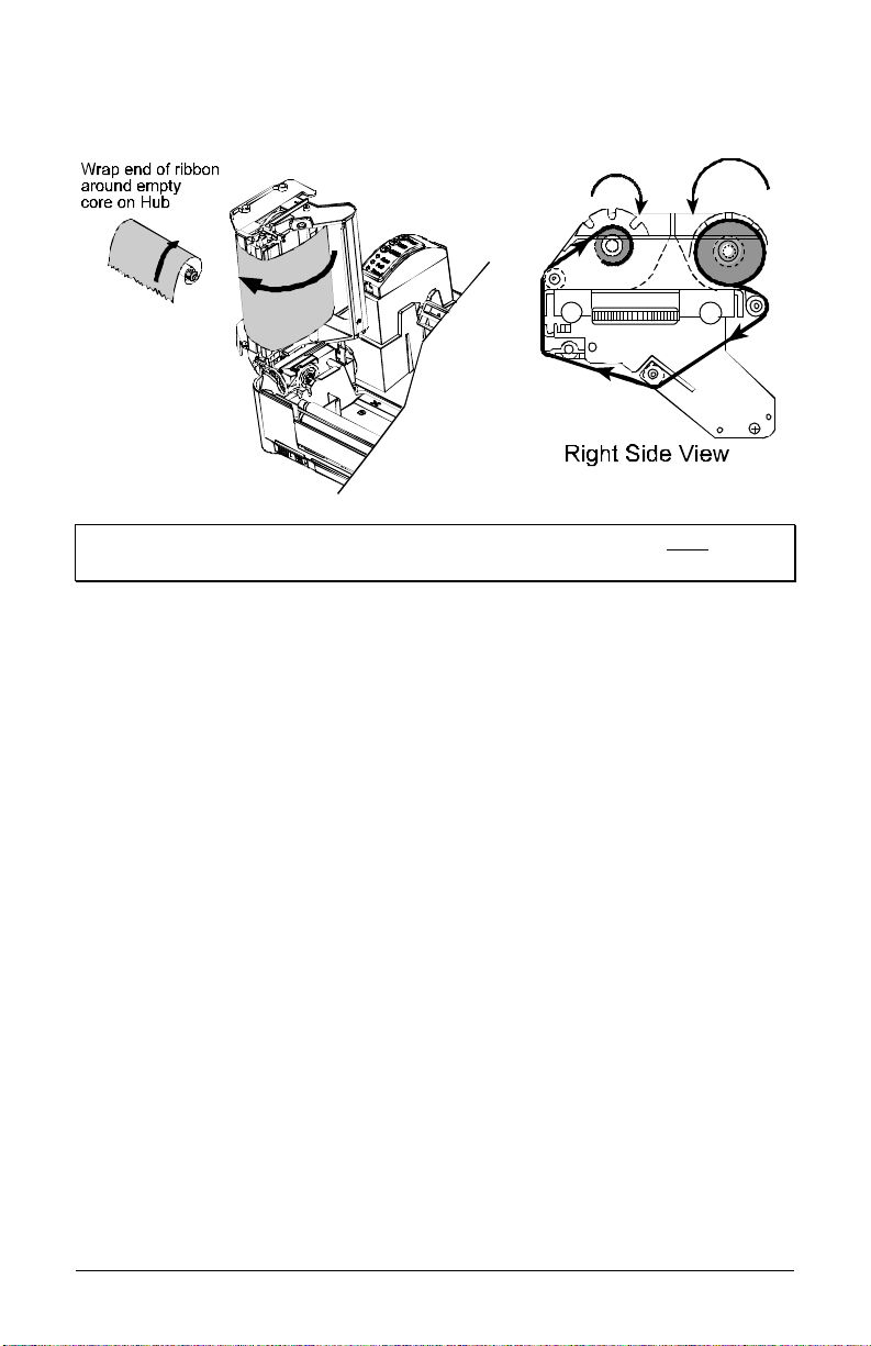
6. Place the Ribbon Hubs back into the printer and route the ribbon
through the Printhead C a rrier As s embly, as s hown below.
;
Note: Ensure the inked side of the ribbon faces the media and NOT the
printhead.
7. The ‘Media Type’ s etting within the printer’s setup must be s et to
‘Thermal Transfer’ to print using a ribbon. See Section 4.4.
16 E-Class
Page 27
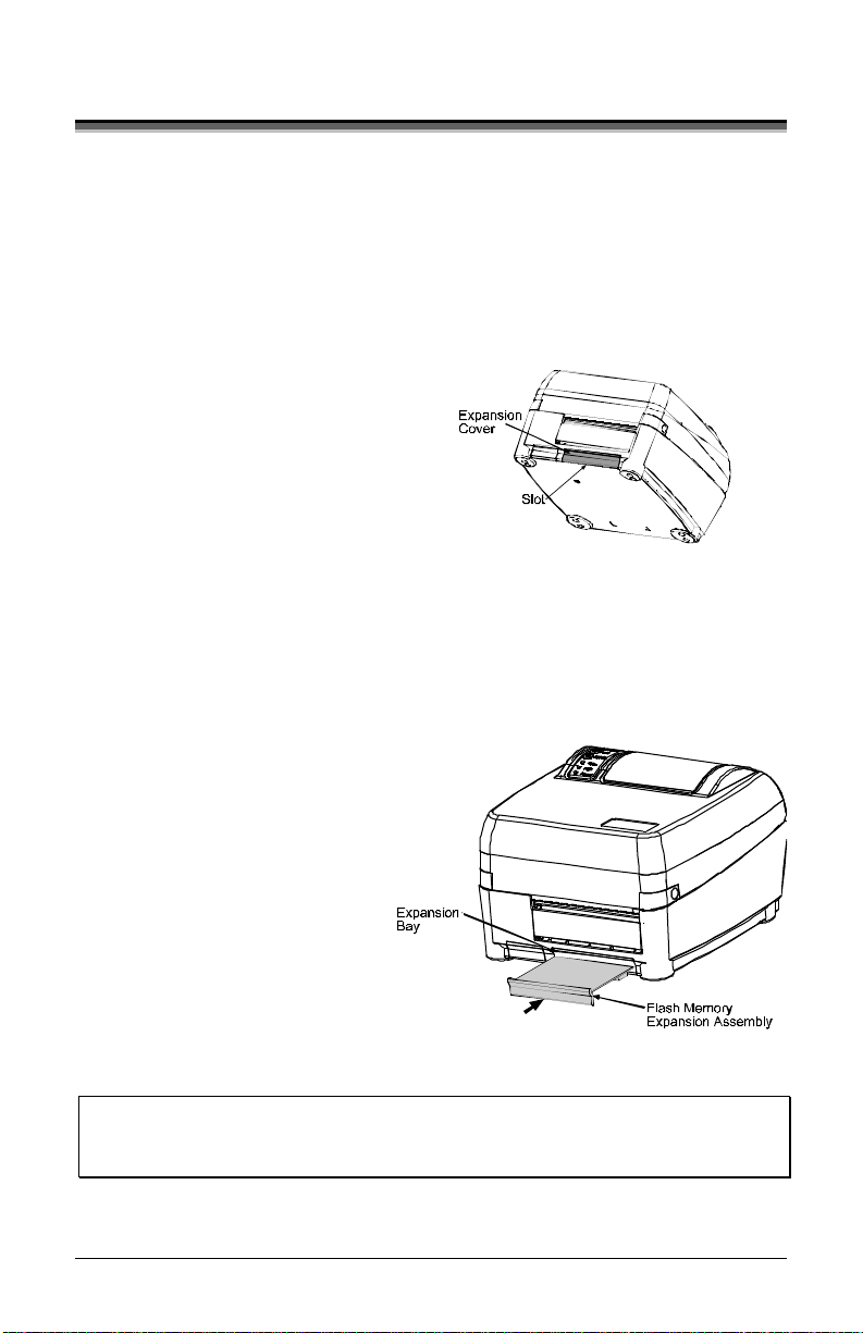
3.5 Flash Memory Expansion
The printer can be equipped with the optional Flash Memory Expansion.
This additional memory can be us e d to s to re la bel formats and fonts (for
fo nt downl oa ding instr uc tions, se e S ec tion 5 .8 ).
To install the Flash Memory Expansion, proceed as follows:
1. T urn the power off and
unplug the printer. Remove
any installed media from
the printer.
2. Using a coin, flathead
screwdriver, or similar
object, insert it into the
Slot on the underside of the
printer and gently pry the
Expansion Cover from the
printer.
3. With its connector facing
down, as shown, gently
insert the Flash Memory
Expansion Asse mbly into
the Expansion Bay until the
ass embly is firmly seated .
4. Plug in and turn on the
printer.
;
Note: When using a blank expansion module for the first time, the printer
will automatically format it upon power-up; this initial format can
take up to one minute to perform.
E-Class 17
Page 28

18 E-Class
Page 29

4.0 Introduction
The Front Panel consists o f
three indicator lights and three
dual-function buttons. T he
functions of these indicators and
controls are liste d be low.
4.1 Lights
¾ Both the POWER and PAUSED Lights will be on during power-up
initialization and a warm rese t.
E-Class 19
Page 30

4.2 Buttons
The three b u tto ns (PA USE, FEED and CA N C EL) perform differe nt
functions ba s e d on the printer’s ope rational mode. T he printer operates in
one of the three following modes:
Normal: Normal printer functions. See Sec tion 4.3.
Printer Setup: Allows c hanges to the printer’s operational settings. See
Section 4.4.
Calibration: A llows the ‘calibration’ of the media be ing used for the
correct sensing of the top of form. See Section 4.6.
4.3 Normal Mode - Button Functions
In ‘Normal’ mode, the printer’s buttons control normal operations su ch as
pause, feed, and cancel, as well as the test and reset functions by using
button combinations as de taile d b elo w.
Normal Mode
(Normal power-up)
Pauses/Un-pauses the printer.
F1
F2
Feeds one label. Al so, clears fault cond it ions.
Press and hold to perfor m Label Alignment; see Section 4.5.
F2
Cancels the curr ent batch of labels.
F3
Press the Pause button to print the next
Button Combinations (push buttons simultaneous ly)
batch of labels (if any) in the print buffer.
+
+
+
Prints the Test Label, see Section 4.7.2.
Performs a warm reset and returns to the Normal Mode
of operation.
Produces Database Configuration and Dot Check Labels.
20 E-Class
Page 31
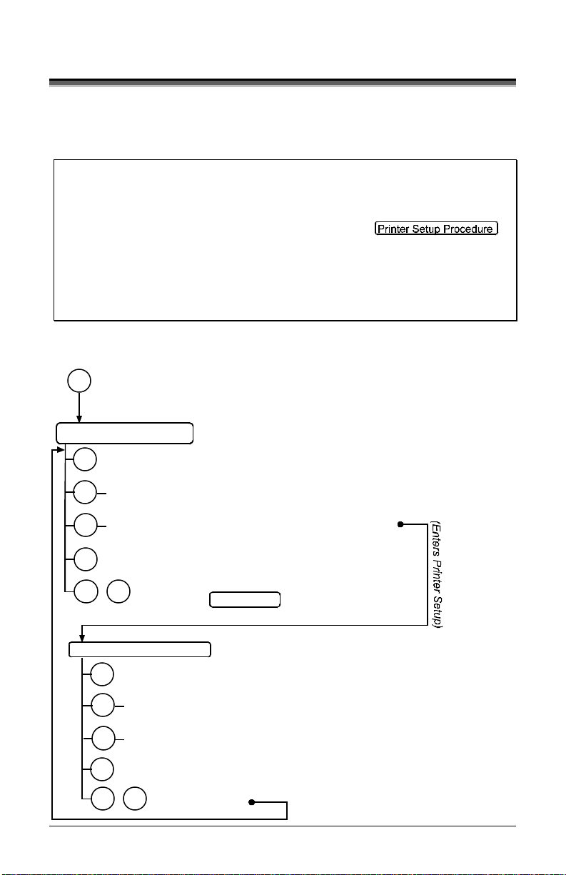
4.4 Printer Setup Mode - Button Functions
In ‘Printer Setup’ mode, the buttons c ontrol the operational settings of
such items as media type, co mmunications, and options as detaile d
below.
;
Notes: It is recommended that the Printer Setup Mode not be entered while
in Peel Mode or with the optional Present Sensor enabled.
Printer and cutter faults are disabled during
If at any time you wish to discard your changes and revert back to
If you wish to restore Factory Defaults see Section 5.7.
To change Printer Setup, proceed as follows:
F1
Printer Setup Mode
Depending on label size, this can cause unpredictable results.
but can s till occur while prin ting “t est” labels.
the previous values, simply turn off power to the printer.
(Press and hold during power-up until the Paused Light turns off)
Prints the ‘Printer Setup Menu List’, see section 4.4.1
F1
,
Press and
F2
(
Release
Press and hold to advance to the desired menu
F2
()
item by counting the number of Fault Light flashes
Prints the ‘Test Label’ for “test”
F3
Saves the current values
F3+
F1
Printer Setup Procedure
and resumes
Increments item’s value
F1
Press and
F2
(
Release
Press and
F2
(
Decrements item’s value
F3
F3+
F1
Feeds one label for “test”
)
Normal Mode
(Current Item and Value is printed)
Selects the next menu item
)
“Direct Select” menu item
)
Hold
Accepts the current
values for “test”
(e.g., 7 Fault Light flashes = Baud Rate,
menu item #7; see Section 4.4.3)
E-Class 21
Page 32

;
Note: When adjusting CONT FORM LENGTH, LABEL WIDTH, or ALIGN
LENGT H, momentar ily press ing F 1 or F2 will change the value by 1;
and, holding either button down until the Fault light flashes will
change the value by ten for each flash.
4.4.1 Printer Setup Menu List
The Printer Setup Menu List label, shown below, contains the printer’s
current values for each menu item that can be modified via the front panel
(See Section 4.4. 2 for a d eta ile d ite m description.)
The Menu Item Numbers c orres po nd to the item’s position in the Menu
List for selection when pressing the
Procedure (see Section 4.4). For example to “Direct Select” the BAUD
RATE Menu Item press and hold the
FAULT Light or for the TOF GA IN item hold
Menu Item
Values
Numbers
1) DIRECT = MEDIA TYPE
2) EDGE = SENSOR TYPE
3) NO = PRESENT SENSOR
4) NO = CUTT ER EQUIP PED
5) 127 = SOP ADJUST, 0.005 in.
6) 127 = PRESENT ADJUST, 0.005 in.
7) 9600 = BAUD RATE, bps
8) 8 = DATA BITS
9) STD = CONTROL CODES
10) 100 = CONT FORM LEN GT H, 0.01 in.
11) 3 = OO S MAXVOLT, 0.1 Volts
12) 12 = TOF GAIN
13) 10 = TOF DELTA, 0.1 Volts
14) 0 = TOF LOW, 0.1 Volts
15) 4 16 = LABE L WI DTH, 0.01 i n.
16) 64 = SCALABL E FONT, 4KB
17) 64 = INTE RNAL MODULE, 4KB
18) NO = LABEL ALIG N MENT
19) 100 = ALIGNMEN T LENGTH, 0.01 in.
20) HOST = STOP LOCATION
21) DPL = INPUT MOD E
22) 10 = HEAT
;
Note: When using narrow media, the ‘Menu Items’ column may be
truncated.
button during the Printer Setup
butto n for 7 fla shes of t he
for 12 fla shes, et c .
Menu
Items
22 E-Class
Page 33

4.4. 2 M enu I t ems and Values
The table be low details the Printer Setup Menu List items with a brief
desc ription of the item’s function, and the possib le v alue s .
1) M EDIA TYPE
Sets printing for direct thermal (no
ribbon) or thermal transfer (ribbon)
media.
Possible Values:
* DIRECT THERMAL
THERMAL TRANSFER
3) PRESENT SENSOR
Enables/Disables the optional
Present Sensor feature.
Possible Values:
* NO
YES
5) SO P ADJUST
Sets the start of print (SOP) location,
relative to the top of form.
Possible Values:
Range: 0 – 255; default = *128
(0 = close to edge; 255 = farthest
from edge)
7) BAUD RATE
Sets the serial port baud rate. (Must
match the host setting).
Possible Values:
600 to 38.4k; default = *9600 BPS
2) SENSO R TYPE
Selects the sensor type used to detect the
media’s Top Of Form (TOF) mark.
Possible Values:
* EDGE: gap / notch TOF marks
REFL (Reflective): black marks
CONT (Continuous): no TOF marks
4) CUTTER EQUIPPED
Enables/Disables the optional Media
Cutter feature.
Possible Values:
* NO
YES
6) PRESENT ADJUST
Specifies an additional amount to feed
the label after printing.
Possible Values:
Range: 0 – 255; default = *128
(0 = close to edge; 255 = farthest from
edge)
8) DATA BIT S
Sets the serial data word length (Must
match the host setting).
Possible Values:
* 8
7
E-Class 23
Page 34

9) CONT ROL CODE S
Allows code selections listed in the
Class Series Programmer’s
Manual.
Possible Values:
* (STD) Standard Codes
(ALT) Alternate Codes
11) OOS MAXVOLT
Sets the media sensor level for the
Out Of Stock condition.
Possible Values:
Range: 0 – 16; default = *2
(Units = .1 volt)
13) T O F DELT A
Sets the minimum media sensor
change required to signify a label
gap or mark.
Possible Values:
Range: 0 – 50; default = *10
(Units = .1 volt)
15) LABEL WIDTH
Sets the label width.
Possible Values:
Range: 75 – 410; default = *410
(Units = .01 inch)
17) INTERNAL MO DULE
Sets the number of memory blocks to
allocate for the internal RAM
module.
Possible Values:
Range: 0 – 128; default
[1]
= *128
(Units = 4K Bytes)
[1]
The E-4304 has a default valu e of 64.
10) CONT FORM LE NGT H
Sets the page (label) size when the
‘SENSOR TYPE’ is set to continuous
media.
Possible Values:
Range: 0 – 9999; default = *100
(Units = .01 inch)
12) T O F G AIN
Sets media sensor Top of Form gain
value.
Possible Values:
Range: 0 – 15; default = *10
14) T O F LOW
Sets the minimum media sensor reading
for paper (gap/notch) or mark
(reflective).
Possible Values:
Range: 0 – 50; default = *0
(Units = 0.1 volt)
16) SC ALAB LE FONT
Sets the number of memory blocks to
allocate for scalable fonts.
Possible Values:
Range: 0 – 128; default = *64
(Units = 4K Bytes)
18) LABEL ALIGNMENT
Sets the label alignment method (see
Section 4. 5)
Possible Values:
.
YES (user manually determines
‘ALIGN LENGTH’)
AUTO (printer determines ‘ALIGN
LENGTH’)
* NO (no Label Alignment used)
24 E-Class
Page 35

19) ALIGN LENGT H
Leading edge distance of two
successive labels. Must be entered if
‘LABEL ALIGNMENT’ is set to
Yes (see Section 4.5).
Possible Values:
0 – 999; default =100*
(Units = .01 inch)
20) ST OP LOCATION
Sets label stopping (and in certain cases
the starting) location for different printer
configurations.
Possible Values:
* HOST (uses host values of ‘SOP’
and ‘PRESENT ADJUST’)
PEEL (sets the stop location just
behind the peel bar of the
optional Peel Mechanism)
CUT (sets stop location at the
blade of the optional Media
Cutter)
COVER (sets stop location at the tear
plate on the printer’s cover)
NONE (uses normal start location
and ignores the host
command)
21) INPUT MODE
Selects between the standard or
template interpretation of incoming
data.
Possible Values:
* DPL (printer constructs the label
using the standard DPL
commands)
LINE (printer constructs the label
using a preloaded template
form)
* = Default Setting
;
Note: All of the menu items listed in the previous section are stored in non-
volatile memory.
22) HEAT
Controls the ‘burn-time’ of the
printhead. This is the equivalent of
Heat Setting on most label software
programs.
Possible Values:
Range: 0 – 30; default = *10
E-Class 25
Page 36

4.4. 3 Step by St ep M odi fication of th e P rinter S et up
The following is an example of Printer Setup modification. Although this
example will detail how to modify the s e rial Baud Rate, the same method
can be used to c hange any of the printer’s menu item settings.
;
Note: It is recommended that the Printer Setup Mode not be entered while in
Peel Mode or with the optional Present Sensor enabled. Depending on
label size this can cause unpredictable results.
1. With printer ‘Off’ and prop e rl y l oa d e d with media, pre ss a nd hold the
button while powering ‘On’ the printer. Continue to hold the
button until the PAUSED Light turns off, then release it.
2. Press and hold the button a nd count 7 flashes of the FAULT Light,
then rele as e it. T he following printout should be produced:
3. Press the button one time to inc rement to the 19200 bps va lue.
The following printout should be produced:
4. At this point you will accept the current values for “test” and exit the
Printer Setup Procedure by simultaneously and briefly press ing the
+
buttons. Wait until the PAUSED Light goe s off.
;
Note: If you wish to discard your changes and revert back to the
previous values simply turn off power to the printer before Step 5.
5. Now you can save your changes a nd resume by
+
simultaneously and briefly pressing the
buttons. Wait until the
PAUSE D Light goes o f f .
26 E-Class
Page 37

6. T o c onfirm that your changes have been made press the
buttons simultaneously, this will print the Data ba s e Co nfiguration
Label. The label should show the new Ba ud Rate value of 19200.
TUE NOVEMBER 15, 2005 19:29 236
VER: E4204 - 04.21 07/28/03
BOOT 83-2279-04H
CODE 83-2280-04W
FONT 83-2431-01A
CPLD 59-2170-01C
INTERNAL FLASH MODULE PRESENT
SYSTEM RAM CHECKS____ GOOD
SYSTEM RAM SIZE___ 2015 KBYTES
SYSTEM RAM AVAIL__ 1244 KBYTES
REG POWER SUPPLY__ YES
INPUT VALUES
PAPER_____________ 255
POT_______________ 113
TRAN______________ 255
REFL______________ 149
RIBN______________ 87
TEMP______________ 48
VOLT______________ 223
CONFIGURATION
DIRECT THERMAL
SERIAL PORT SELECTED
19.2; 8BITS
EDGE
CONT FORM LENGTH__ 0
PRESENT ADJUST____ 127
SOP ADJUST________ 127
TOF LOW___________ 0 0
TOF DELTA_________ 10 10
TOF GAIN__________ 12 10
OOS MAXVOLT_______ 3 3
LABEL ALIGNMENT___ NO
ALIGN LENGTH______ 100
STOP LOCATION_____ HOST
IMPUT MODE________ DPL
HEAT______________ 10
COUNTER INFORMATION
ABSOLUTE VALUES 6-18-2004
LENGTH____ 773 INCHES
TIME______ 20 HOURS
RESETTABLE VALUES 6-22-2004
LENGTH____ 576 INCHES
TIME______ 10 HOURS
MEMORY CONFIGURATION
INTERNAL MODULE A______128
SCALABLE FONTS__________64
LABEL SIZE 0416:02157 IN
+
The new
19200
Baud
Rate
E-Class 27
Page 38
4.5 Label Alignment
The Label Alignment function is intended for use when the label length is
less than the distance between the printhead and the media sensor or
where label waste at power-up is a concern. Label Alignment (see table
below) is not recomme nded for label le ngths greater than 6.5 inches o r for
media conta ining 2 o r more form le ngths .
Label Stock Label Alignment Setting
Continuous NO
6.5 inches or less YES or AUTO
6.5 inches or more NO
Multiple length labels NO
The Label Alignment function is chosen via the menu system (see Section
4.4) or by host commands. T he three possible modes, YES, AUTO, and
NO, are deta iled in the following sections.
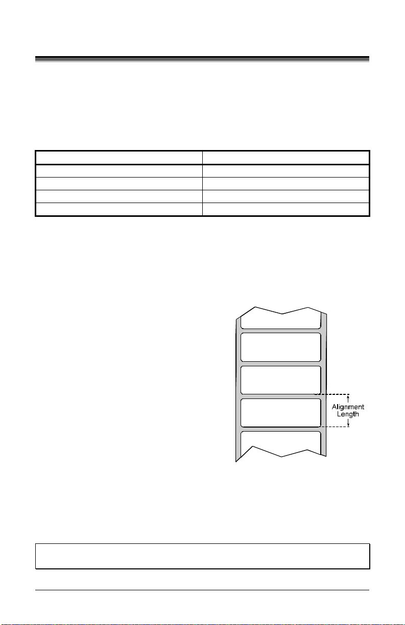
4.5. 1 Label Al ign ment = YES
In this mode, the operator must supply an
‘ALIGN LENGTH’ value. This value
must be physically measured from leading
edge to leading edge of two successive
labels, as shown. The measurement must
be as accurate as possible. For very short
labels , errors as s mall as 0. 0 1” c a n result
in noticeable print variations on the labels
between the media sensor and the
printhead.
The measured value must be sent to the printer via the host computer or
entered using the Printer Setup Mode (see Section 4.4).
Then, in Normal Mode, press and hold the FEED button (about 4
seco nds). T he printer will align the labe l to the top of form position.
; Note: If media with a different label length is subsequently loaded, the ‘ALIGN
LENGTH’ must be recalculated and re-entered.
28 E-Class
Page 39

4.5. 2 Label Al ign ment = AUT O
In this mode, the printer automatically c a lcula te s the ‘ALIG N LENGTH’
thus eliminating the need to physica lly meas ure the labe l. T his mode is
usually preferred in applications that require frequent media changes to
lab els of dif fe r ent le ngths .
To perform an Auto Alignment, in Normal Mode press a nd hold the
FEED button (about 4 sec onds). T he printer will feed labels to c a lcula te
the label length. Following the ca lc ula tion, the printer will save the
measurement and align to the top of form position. Auto Alignment can
result in wasted labels during the measurement proces s (the longer the
label length the greater the waste).
Special Case Auto Alignment when the Present Sensor enabled -
If the printer is equipped with the Prese nt Sensor option and tha t fea ture
is enabled, while the labe l length is be ing calculated the printer will pause
and illumina te the PAUSE Light after each movement. You must press
the Pause Button for the alignment to continue. This allows you to
remove any labels as required; however, labels should not be forcibly
removed since they may not actua lly be pos itio ned for removal but only
at an interim p os ition required for measurement.
4.5. 3 Label Al ign ment = NO
When Label A lignme nt is not enabled (i.e. , s et to NO ), printing begins at
the current label position without alignme nt, assuming the label is a t the
start of print position. Additionally, if the label length is short, labels
between the printhead and the media se nsor may be unused.
E-Class 29
Page 40

4.5.4 Label Alignment Troubleshooting
If you experience label alignme nt problems, the following table offers
possible causes and solutions.
Problem Possible Cause Solution
Attempting to
perform Label
Alignment results
in no paper
movement.
With the Present
Sensor enabled,
Label Alignment
cannot be
performed without
a Label Length.
¾ Set Label Alignment to AUTO,
press and hold FEED until
media moves for the automatic
length measurement.
~OR~
¾ Re-measure the Label
Alignment Length. Use Printer
Setup mode to enter the new
length. Print a Database
Configuration label to ensure
the new length has been set.
30 E-Class
Page 41

Problem Possible Cause Solution
First label is
wasted during
alignment. All
labels thereafter
print to the correct
start of print
position.
Alignment Length is
too long.
~OR~
For labels whose
length and stop
position cause them
to stop between
labels on the media
sensor, the
alignment function
can result in wasted
labels.
¾ Set Label Alignment to AUTO,
press and hold FEED until
paper moves for automatic
Label Alignment length
measurement.
¾ Re-measure Label Alignment
Length, use Menu Setup to set
new length, ensure desired
length has been set.
¾ Obtain a slightly different label
Alignment Length
measurement. Using the Label
Alignment AUTO mode, hold
the FEED button to force an
alignment and label
measurement. Ensuring slack
in the label stock may result in
a slightly different
measurement. The Alignment
Length may also be set
manually via the Setup Menu.
Increasing or decreasing the
value by 1 or 2 units (in./100)
may help to prevent the wasted
labels; however, this may
result in incorrect print
positions for labels that are
short in length.
~OR~
E-Class 31
Page 42

Problem Possible Cause Solution
Label Alignment is
incorrect. Pressing
FEED
successively
results in a short
label length, oneinch.
Label Alignment
Length is not
correct. The
default Label
Alignment Length is
1.00”, and will
result in this
behavior when any
larger label length
is used without
setting the
appropriate length.
¾ Set Label Alignment to
AUTO. Press and hold FEED
until paper moves for
automatic Label Alignment
Length measurement.
¾ Measure the label length and
use the Setup Menu to set the
new length. Print a Database
Configuration label to ensure
the new length has been set.
Label Alignment is
incorrect. Pressing
FEED
successively
results in a label
length longer than
actual, one-inch.
Label Alignment
Length is not
correct. The
default Label
Alignment Length is
1.00”, and will
result in this
behavior when any
larger label length
is used without
setting the
appropriate length
¾ Set Label Alignment to
AUTO. Press and hold FEED
until paper moves for
automatic Label Alignment
length measurement.
¾ Measure the label length and
use the Setup Menu to set the
new length. Print a Database
Configuration label to ensure
the new length has been set.
~OR~
~OR~
32 E-Class
Page 43

+
Problem Possible Cause Solution
Tear Mode is
selected but the
label stop position
(present position)
is not far enough
forward.
Another present
position has been
determined.
Enabling the
Present Sensor
causes the label
stop position
(present position)
to be approximately
0.1” behind the
peel bar.
~OR~
¾ Disable the Present Sensor.
¾ Ensure the host computer is
not providing a Present
Distance shorter than is
required for the Tear Bar.
¾ Use the Setup Menu to modify
the Present Adjust value.
The Present Adjust
value is not correct.
Tear Mode is
selected but the
label stop position
(present position)
is too far forward.
The FAULT
Indicator
illuminates during
label alignment.
Another present
position has been
determined.
~OR~
The Present Adjust
value is not correct.
The label supply is
empty
¾ Ensure the host computer is
not providing a Present
Distance longer than is
required for the Tear Bar.
¾ Use the Setup Menu to modify
the Present Adjust value.
¾ Load media.
~OR~
E-Class 33
Page 44

4.6 Calibration Mode – Button Functions
In ‘C alibra tion’ mode, the buttons allow the printer to adjust to the media
being used. Calib ration can be performed either automatically or
manually, as de taile d be low.
;
Notes: Before calibrating, ensure that the Printhead Carrier Assembly is
latched down, that the cover is closed, and that the media sensor has
Printer and cutter faults are disabled during
If at any time you wish to discard your changes and revert back to the
To p e rfo rm Ca lib ra t io n:
been set for the appropriate media type, see Section 4.4.2.
and
, but can still occur while print ing “test ” labels.
previous calibration simply turn off power to the printer. Also, Factory
Defaults can be restored, see Section 5.7
F3
(Press and hold during power-up until the Paused Light turns off)
Calibration Mode
F1
Auto Me dia Ca libr ation
Press and
F2
(
Release
Press and hold until the
F2
(
Paused Light turns on
Prints the ‘Test La bel’ for “te st”
F3
Saves the current values
F3+
F1
Media Sensor Calibration
and resumes
Ana l yz e me dia
F1
F2 Analyz e me dia bac king mater i al or re f lective mark
Analyze no media condition
F3
F1F3+
Accepts the current
analysis for “test”
(See Section 4.6.1)
Feeds one label for “test”
)
)
Normal Mode
(See Section 4.6.2)
(The Fault Indicator flashes during analysis)
34 E-Class
Page 45

4.6.1 Auto Media Sensor Calibration
Auto Media Sensor Ca libration automatically e s ta blis hes the optimum
sensing va lues for the media you are using in the printer.
;
Note: Before calibrating, be sure the media sensor is set for the appropriate
media type, see Section 4.4.2; also, ensure that the Printhead Carrier
Assembly is latched down and the cover is closed.
To automatically calibrate the media sensor, proceed as follows:
1. With the desired media loaded, hold the button while powering up
the printer. C ontinue to hold the button until the PAUSED Light turns
off then release it.
3. Ne xt press the
button. The printer w ill f e e d appr oxim ately ten
inches of media to calculate the TOF Delta and Low values to be
used.
Upon completion, one of the following Indicators will flash five times
4.
to denote the result of the auto calibratio n attempt:
PAUSED Light = Successful calibration. Proceed to Step 5.
FAULT Light = Unsuccess ful calibration. Proceed to Section 4.6.2.
;
Note: If you wish to discard the changes and revert back to the
previous calibration simply turn off the printer before Step 5.
5. Now save the changes and resume
+
buttons simultaneously and briefly. Wait until the PAUSED
by pressing the
Light goe s off .
E-Class 35
Page 46

4.6.2 M anual Media Sensor Calibration
The Manual Media Sensor Calibration procedure should be used in cases
where the printer continues to suffer from media sensing problems after
performing or attempting to perform the Auto Media Se nsor Ca libration
(see Section 4.6.1).
;
Note: Before calibrating, be sure the media sensor is set for the appropriate
media type, see Section 4.4.2; also, ensure that the Printhead Carrier
Assembly is latched down and the cover is closed.
To manually calibrate the media sensor, proceed as follows:
Hold the button and power-up the printer. Continue to hold the
1.
button until the PAUSED Light turns off; the n releas e the button.
Next, press and hold the
the PAUSED Light turns on; the n releas e the button.
2. Place the media with the backing attached (if any) over the media
sensor (see Section 3.2 for the sensor’s location), close the Printhead
Carrier Assembly, and then press the
flash the FAULT Light as it analyzes the mate rial.
3. Pos itio n the backing mate rial o r the black (reflec tive ) mark over the
media sensor, close the Printhead Carrier Assembly, and then press
button. The printer w ill f las h the FAULT Light as it analyzes
the
the top of f or m m ar k.
4. Remove all the material from the media sensor, close the Printhead
Carrier Assembly, and then press the
flash the FAULT Light as it analyzes the no media condition.
5. Simultaneously and briefly press the
calibration for “test” and exit the
following Indicators will flash five times to de note the result of the
manual ca libration attempt:
PAUSED Light = Successful calibration. Proceed to Step 6.
FAULT Light = Unsuccess ful calibration. Retry the procedure
begi nni ng at Step 1.
6. Use the
button (feeds a labe l), and the butto n (prints a test labe l)
to test the current calibration.
button, continue to hold the button until
button. The printe r w ill
button. The printe r w ill
buttons to accept the
+
. One of the
36 E-Class
Page 47

;
Note: If you wish to discard the changes and revert back to the
previous calibration simply turn off the printer before Step 7.
7. Now save the changes and resume
+
buttons simultaneously and briefly. Wait until the PAUSED
by pressing the
Light goe s off .
4.7 Internal Labels
The following section details the printer’s reside nt labels .
4.7. 1 The Database Con f igu rat ion Label
The Databa s e C onfiguration Label provides va lua ble printer informa tion
including the firmware vers ion, memory allocations, enabled options, and
label-counter data.
To print the Database Configuration Label, proceed as f ollow s:
With the printer on, loaded with media (at least 4 inches wide) and ribbon
(if printing with the rmal transfer media), press the
simultaneously.
+
buttons
E-Class 37
Page 48

TUE NOVEMBER 15, 2005 19:29 236
VER: E4204 - 04.21 07/28/03
BOOT 83-2279-04H
CODE 83-2280-04W
FONT 83-2431-01A
CPLD 59-2170-01C
INTERNAL FLASH MODULE PRESENT
SYSTEM RAM CHECKS____ GOOD
SYSTEM RAM SIZE___ 2015 KBYTES
SYSTEM RAM AVAIL__ 1244 KBYTES
REG POWER SUPPLY__ YES
INPUT VALUES
PAPER_____________ 255
POT_______________ 113
TRAN______________ 255
REFL______________ 149
RIBN______________ 87
TEMP______________ 48
VOLT______________ 223
CONFIGURATION
DIRECT THERMAL
SERIAL PORT SELECTED
19.2; 8BITS
EDGE
CONT FORM LENGTH__ 0
PRESENT ADJUST____ 127
SOP ADJUST________ 127
TOF LOW___________ 0 0
TOF DELTA_________ 10 10
TOF GAIN__________ 12 10
OOS MAXVOLT_______ 3 3
LABEL ALIGNMENT___ NO
ALIGN LENGTH______ 100
STOP LOCATION_____ HOST
IMPUT MODE________ DPL
HEAT______________ 10
COUNTER INFORMATION
ABSOLUTE VALUES 6-18-2004
LENGTH____ 773 INCHES
TIME______ 20 HOURS
RESETTABLE VALUES 6-22-2004
LENGTH____ 576 INCHES
TIME______ 10 HOURS
MEMORY CONFIGURATION
INTERNAL MODULE A______128
SCALABLE FONTS__________64
LABEL SIZE 0416:02157 IN
The sec ond label printed is the Te s t Label. This label is u s ed to c heck
the condition of the printhead, as s hown below:
Faulty Label:
Instead of consistent patterns,
streaks in the direction of print
indicate a dirty or faulty
printhead. See Section 5 for
cleaning instructions.
38 E-Class
Page 49

4.7.2 Test Label
The Tes t Label is u s ed to e valu ate the current printer setup for print
quality, label trac king, and print positioning.
To print the Test Label, proceed as f ollow s :
With the printer loaded with media (at lea s t 4 inches wide), and ribbon (if
printing with thermal transfer media), simultaneously pres s the
buttons.
+
4.7. 3 Hex Dump Lab el
The Hex Dump Label is a us e ful tool in the diagnosis of problems
includ ing c ommunic atio ns handshak i ng and DP L synta x errors . To
generate a Hex Dump La be l the printer enters into Hex Dump Mode. In
this mode, all da ta s ent to the printer will be immediate ly o utput in
hexadecimal code, along with the printable ASCII equivale nts. To de code
this information, the Class Ser ies Progr amme r ’s Manual is a n ess e ntial
refere nce . As a final note , many so ftware p ro grams use bit mapp ing to
construct the label, making dia gnosis of this data difficult. C ontact
Datamax Technical Support with any questions.
E-Class 39
Page 50

To enter Hex Dum p Mode and print a He x Dump Label, pr oceed as
follows:
With the printer on, loaded with media (at least 4 inches wide) and ribbon
(if printing with the rmal transfer media), press and hold the
while turning the printer on. Continue holding the
button until the
button
PAUSED Light turns off. Now, all data received by the printer will be
output in hexadecimal code, as shown below.
To exit the H ex Du mp Mode , turn the pr inte r off.
40 E-Class
Page 51

5.0 Introduction
This section details the cleaning, adjusting, and troubleshooting tips for
the printer. T he following table outlines the recommended maintenance
schedule for the various printer parts.
Area Method Interval
Turn off the printer before cleaning the
Printhead
printhead. Use solvent* on a cotton
swab to clean the printhead from end to
end.
After every roll
of media.
Turn the power off. Rotate the platen
Platen Roller
roller and clean it thoroughly with
solvent* and a cotton swab.
Rotate the peel-off roller and clean it
Peel-Off Roller
thoroughly with solvent* and a cotton
swab.
Media Path Solvent*
After every roll
of media.
After every roll
of media.
After every roll
of media.
Peel/Tear Bar Solvent* As needed
Media Sensor Blown air or brush Monthly
Exterior Mild detergent or desktop cleaner. As needed
Interior Brush or vacuum cleaner As needed.
* It is recommended that a solvent containing isopropyl alcohol be used.
Isopropyl alcohol is a flammable solvent, always t ake the proper
WARNING
E-Class 41
precautions when using this substance.
Page 52

5.1 Cleanin g the Print head
To cle a n the printhead, follow the instructions below.
Before servicing, disconnect the printer from the AC outlet.
WARNING
1. Turn ‘off’ a nd unplug the printer. Ope n the cov e r.
2. Pus h the Printhe ad Latch down a nd raise the Printhead C a rrier
3. Using a Cotton Swab dipped in isopropyl alcohol, rub the Cotton
Asse mbly. Allow the Printhe a d to c ool.
Swab along the Printhead.
42 E-Class
Page 53

5.2 Media Wid t h Ad ju st ment
A Thumbwheel on the sid e of the Printhead C a rrier As s embly allows the
printhead to be adjusted for various sizes of media. Whe n adjusting for
narrow media move the Thumbwheel to the left (clockwise); conversely,
when adjusting for wide media move it to the right (c ounterclock wise).
;
Note: The numbers on the Thumbwheel are for reference only and do not
correspond to specific media widths.
To perform a media width adjustment, proceed as follows:
+
1. Load media into the printe r. Print a label (pres s the
buttons
simultaneously) and examine it.
2. If the printing appears too light on the right-hand side of the label (see
example below), then move the Thumbwheel counterclockwise. Print
another label and examine it; make additional adjustments as
necessary.
E-Class 43
Page 54

If the printing is light on
the right side of a labe l,
make a counterclockwise
adjustme nt w ith the
Thumbwheel.
Direction
of Media
Movem ent
;
Note: If the media begins tracking too far to the right while printing, the
Thumbwheel should be adjusted to the clockwise.
5.3 Ribbon Width Adjustment
The adjustable ribbon handler feature, found on printers equipped with
the thermal transfer option, allows the optimum amount tension to be
supplied by the ribbon supply hub. Adjust the ribbon tension as follows:
1. Turn ‘off’ the pri nter.
2. Hold the Hub and then rotate the Ribbon Tension Adjustment Knob
to meet your media/ribbon width based on the table below. Ensure
that the Ribbon Tension Adjustment Knob is turned fully to the
clockwise or co unterclockwise p os ition. (T he knob will no longer
turn once it is in the proper position; do no t force this knob.)
44 E-Class
Page 55

Ribbon Size Ribbon Width Direction of Rotation
Narrow 1 - 2 inches Clockwise
Wide 2 - 4 inches Counterclockwise
E-Class 45
Page 56
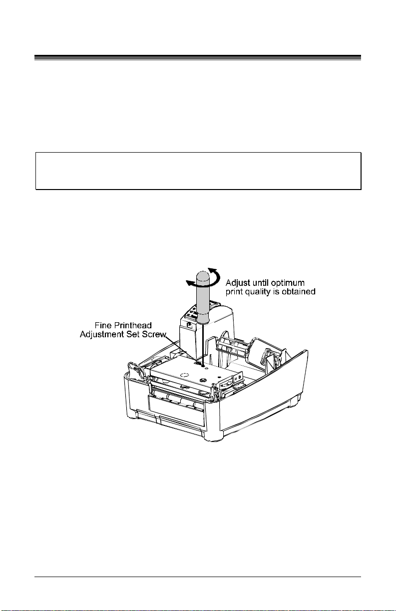
5.4 Fine Printhead Adjustmen t
The Fine Printhead Adjustment Set Screw, located on top of the printhead
carrier assembly, is used for adjus ting print quality. This adjustment is
set at the factory and should not need further adjustment; however, with
the different types and thickness of media some re-adjustment may be
necessa ry if print quality suffers .
;
Note: If thermal transfer equipped, it is not necessary to remove the
Ribbon Handler Assembly; an access hole through the assembly is
provided.
To adju s t the printhead, turn the Set Screw until optimum print quality is
obtained (some trial and error may be neces s ary). Do not over tighten the
Set Scre w.
46 E-Class
Page 57

5.5 Printhead Replacement
;
Notes: Always follow proper Electro Static Discharge procedures when
If thermal transfer equipped, it is not necessary to remove the
Remove the printhead as follows:
1. Turn off the pri nter.
2. Loosen the Printhead Screw
3. Press the Printhe a d Latch
4. Remove the printhead cable
Replace the printhead as follows:
1. C o nnect the printhead cable to the new printhead.
2. Pos itio n the printhead in the printhead carrier ass e mbly, ensure that
3. C lea n the Printhead (see Se c tion 5.1) and allow it to dry before
4. Use the Darkness Adju s tment to match the print contrast of the new
replacing the printhead.
Ribbon Handler Assembly; an access hole is provided.
until the printhead is freed.
then raise the carrier
assembly.
from the back of the
printhead.
the printhead cable is not pinched, and then tighten the Printhe ad
Screw.
use.
printhead to that of the old printhe a d (s ee Se ctio n 5.6).
E-Class 47
Page 58

5.6 Darkness Adjustment
The Darkness Adjustment (located on the rear of the printer) allows the
operator to match the print contrast following a printhead replacement.
Turning the Darkness A djus tment clockwise will darken the print, while
turning it counterclockwise will lighten the print. Compare a la be l printed
with the old printhe a d a nd make this adjustment so that the new printhead
matches the darkest portion of that label.
;
Note: Large increases in the ‘Darkness Adjustment’ can shorten printhead
life. If you need to increase the darkness of the printed labels,
increase the Heat value and/or slow the Print Speed using your
software program or via DPL commands.
5.7 Resetting t o the F act ory Defaults
With the printer power ‘Off,’ press and hold the F1, F2, and F3 buttons
while turning ‘On’ the printer. C ontinue to hold the buttons down until
the PAUSED Light turns off. T he printer will no w be se t to the ‘Factory
Defaults . ’ See Se c tion 4.4. 1 for a lis ting of the factory de fau lt s ettings.
5.8 Downloading Firmware and Fonts
The operating programs and fonts for the printer are stored in Flash
memory on the Main PCB. When program upda tes and/or new fea tures
are added, they can be downloaded to the printer as follows:
Identify the new version for your model of printer from the Da tamax
1.
FTP site a t ftp://ftp. da ta maxcorp.com
and download it onto your
computer’s hard drive or a floppy disk.
2. Ensure that the printer is connected to the host and that the power is
‘On.’ Us ing the DOS copy c ommand enter:
;
Note: Other programs (e.g., hyper-terminal and certain Windows
48 E-Class
copy filename.dlf lpt1/b
Driver programs) may also be used to download this file.
®
Page 59

3. T he PAUSED Light will flash during the download.
4. Follo wi ng a s uc c e s s ful dow nloa d, the PAUSED Light will
illuminate then the printer will perform a ‘cold res e t. ’ T he previous
printer setup will not be a ffecte d unless substantial firmware data
structure changes have occurred. Print a Database Configuration
Label to verify your new firmware version.
¾ Follow ing a n uns uc c e s sful downloa d, the FAULT Light will
illuminate then the printer will perform a ‘warm reset’ (both the
POWER and PAUSED Light will be on during power-up
initialization). The original firmware will remain operational. If
the printer fai ls to re s e t , toggle the po wer ‘O ff’ a nd ‘On.’
Try re-se nding the file to the printer. If the failure continues,
check the following possible causes:
• An invalid or corrupted file is being downloaded - Ensure the
file being downloaded is correct and applicable for your
printer model.
• Possible communications error - Check the cable connection
between the host and printer and ensure that a qua lity,
shielded cab le is u s ed .
• Possi bl e Fla sh memory pro bl e m - Cal l fo r s e rv ic e .
If the printer fails to boot-up after an unsucce ss ful download, turn
‘Off’ the power. Simulta neou s ly p ress a nd hold the F1 a nd F3
buttons while powering ‘On’ the printer. Now, try downloading
the file to the printer.
E-Class 49
Page 60

50 E-Class
Page 61

6.0 Introduction
Occasionally, situations arise that require troubleshooting. Possible
problem situations and potential solutions are lis ted in this section. While
not every situation is address ed, you may find some of these tips helpful.
After the correction action is taken press the FEED button to clear the
alarm. Contact a qualified service technician for problems that persist or
are not covered in this section.
6.1 Troubleshooting Tips
The following table lists the symptoms and the associated page numbers
of the topics c overed in the troubleshooting s ec tion.
Problem Page
Unacceptable print quality 52
The printer does not print or prints several labels at once 52
The ribbon does not advance 52
Skips every other label 53
Unable to print in rotation 4 53
Prints light on the right side of the label 53
Printer fails to turn on 53
Label advances 1-2 inches before a fault indication 54
Label advances 16 inches before a fault indication 54
Tracking Problems 54
E-Class 51
Page 62

Unacceptable print quality:
• Dirty printhead: Clean the printhead (see Section 5).
• The temperature setting may be incorrect for the media being
used: Use the software program or DPL commands adjust the
Heat Setting and Print Speed.
• A mismatched inc orrect ribbon/me dia c ombination is being
used: Check the types being used.
• Verify tha t the Media T ype Switch is in the correc t pos ition
for the printing method being used (see Section 3.4).
• Faulty printhead: Replace it (see Section 5) or call for service.
The printe r does no t print or prints s e veral la be ls at once :
• The labels are incorrectly loaded: See the loading
instructions on the inside c ove r of the printer or Section 3.
• The media is not calibrated: Ca librate it (s ee Sec tion 4).
• If equipped, the Adjustable Media Sensor may need to be
repositioned (see Se ction 3).
• The media sensor or sensor circuitry ma y be de fective: C all
for se rv ic e .
The ribbon doe s not advance (the paper advances, but ribbon does not):
• The ribbon may be installed incorrectly: Ensure that the
ribbon’s inked side faces the paper. With most ribbons this
can be verified by rubbing paper against the ribbon; the ink
should smudge the paper. Or, if using la bel s tock, the sticky
side of a la be l will pull off the ink.
• A mismatched ribbon/paper combination is resulting in an
insufficient amount of friction betwe en paper and ribbon:
Ensure that the correct type of ribbon is being used with the
media.
52 E-Class
Page 63

Skips every other label (print quality is good, but every other label is
skipped):
• The label is formatted too clos e to the top edge of the label:
Leave white space equal to 8-dot rows (about .02 inch
[. 5mm]) at the top of the labe l.
• The media is not calibrate d: C a librate it (s ee Sec tion 4).
• If equipped, the Adjustable Media Sensor may need to be
repositioned (see Se ction 3).
• The media s ensor or media sensor circuitry may be
defe c ti ve : C a l l fo r s e rv i c e .
Unable to print in rotatio n 4 :
• The characters are formatted outside the dimensions of the
label: Check that the row/column va lue s provid e e nough
room for the height of the image being printed.
Prints light on the right side of the label:
• The media width adjustment is set for a narrower media
width than is actually being used: Adjus t for the media width
(see Section 5).
• The printhead is not properly aligned: Call for service.
• The printhead carrier as s e mbly is not latched down: Latch it.
Printer fail s to pow e r on:
• The AC wall outlet may be faulty: Try a nother outlet.
• A fuse may be blown: Call for service.
• The powe r supply may be faulty: Replace it.
• A defective power switch may exist on the printer: Call for
service.
E-Class 53
Page 64

Label advances 1-2 inches before a fault indication:
• The ribbon may be incorrectly installed. Ensure that the
ribbon’s inked side faces the paper. With most ribbons this
can be verified by rubbing paper against the ribbon; the ink
should smudge the paper. Or, if using la bel s tock, the sticky
side of a la be l will pull off the ink.
• A mismatched ribbon/paper combination is res ulting in an
insufficient amount of friction betwe en paper and ribbon:
Ensure that the correct type of ribbon is being used with the
media.
Labe l advanc e s 16 inc he s be fo re a fa ult indi c ati on:
• The media may not be properly loaded: Reload it (see
Section 5). When loading media ensure that the media hub
and media guide are against the media and that gaps or marks
in the labels a re in line with the media s e nsor.
• If equipped, the Adjustable Media Sensor may need to be
repositioned (see Se ction 3).
• The media s ensor or media sensor circuitry may be
defe c ti ve : C a l l fo r s e rv i c e .
Labe ls mo ve e xc ess ivel y from side to s i de during printing:
• The media may not be properly loaded: Reload it (see
Section 5). When loading media ensure that the media hub
and media guide are against the media and that gaps or marks
in the labels a re in line with the media s e nsor.
The me dia width adjustment may not be properly set:
•
Readjust for the label width (see Section 5).
54 E-Class
Page 65

Mechanical
Width 8.5 inches (21.6 cm)
Depth 9.5 inches (24.1 cm)
Height 6.25 inches (15.9 cm)
Weight 4 pounds (1.8 kg)
Operating Temperature
AC Input Voltage
40° to 95° F (4° to 35° C)
Power Supply
(50-2050-01); 100 VAC to 240 VAC / 50-60 Hz
Printing
Print Method Direct Thermal; Thermal Transfer (optional)
Print Speed
Resolution
1 - 4 IPS (25.4 - 101.6 mm/s)
E-4204: 203 DPI (8 dots/mm)
E-4304: 300 DPI (11.8 dots/mm)
Tear Bar Tear up
DRAM Memory 2MB
FLASH Memory 1MB
E-Class 55
Page 66

Media / Ribbon
Media Types Roll-Fed, Die-Cut, Continuous, Fan-Fold
Max. Media Width 4.3 inches (109.2 mm)
Min. Media Width 1 inches (25.4 mm)
Max. Print Width 4.09 inches (104 mm)
Print Length Range
Media Thickness Range .0025 - .01 inches (.064 - .254 mm); up to .007
Media Supply Roll
Capacity
Ribbon Width Range 1.0 - 4.3 inches (25 - 110 mm)
.375 – 24.0 inches (9.52-609.6 mm); min length of
1 .25 inches (31.8mm) with optional Cutter.
inches (.117 mm) with optional Cutter; up to .005
inches (.127 mm) with optional LD Cutter
5 inches (127.0 mm) O.D. on a 1 inch (25.4 mm)
core
Ribbon Roll Capacity
Matched to media: approx. 361 feet (110 m) long
with a 1.5 inch (38 mm) O.D. on a .5 inch core
Comm unications
Interface USB, RS-232 (DB-9), and Centronics Parallel
Baud Speed 600 to 38,400 bits per second (BPS)
Handshaking Xon/Xoff, CTS, DTR
Parity Even, Odd, or None
Stop Bits 1 or 2
Data Bits 7 or 8
Fonts
9 Bit Map Fonts; rotated 0, 90, 180, and 270 degrees.
Embedded Bar Codes
Code 39, Interleaved 2 of 5,Code 128 A, B & C, Codabar, LOGMARS, UPC-A,
UPC-E, UPC 2&5, EAN-8, EAN-13, EAN 2&5, UPC Random Weight, Code 93,
Plessey, USCS, Code 128 MOD 43, Postnet, USS/EAN-128 Random Weight,
Telepen, UPS Maxicode, PDF417, DataMatrix, Aztec, QR Code, MicroPDF417,
and TLC39
56 E-Class
Page 67

A
Approved Media
To achieve optimum print quality and maximum printhead life, Datamax specifies the use
of DATAMAX
in our printers; use of non-Datamax supplies may affect the print quality, performance,
and life of the printer or its components.
For a current list of approved media and ribbons for use in direct thermal and thermal
transfer applications, please contact a Media Representative at (407) 523-5650.
®
brand media and ribbons. These supplies are specially formulated for use
G
F
I
H
J
E
B
Designator Description Maximum
D
C
[1]
Minimum
A Label width 4.09 1.00
B Backing width 4.30 1.00
C Gap between labels .25 .10
D Label length 24
E Total thickness .010
[3]
.375
[6]
.0025
[4]
F Notch opening width .50 .20
G
Distance from the edge of the media to
the media sensor aperture (left justified)
.175
.125
with the Adjustable Media Sensor option 2.94 .125
H Reflective mark width
I Distance between reflective marks 24
[2]
4.10 .50
[3]
.375
[5]
J Reflective mark length .25 .10
[1]
Units of measure are in inches.
[2]
The reflective (black) mark must be carbon based, placed on the backside of the stock,
and the reflectance shall be less than 10% at wavelengths of 950 and 640 nm.
[3]
The label length may vary up to 99 inches with printable area not exceeding the
maximum lab el lengt h.
[4]
This distance is inclusive of the minimum gap between labels. Min length of 1.25 inches
(31.8mm) with optional Cutter installed.
[5]
This distance is inclusive of the minimum reflective mark.
[6]
.007 inches (.117 mm) w/Standard Cutter, .005 inches (.127 mm) w/LD Cutter
[1]
E-Class 57
Page 68

58 E-Class
Page 69

ASCII Control Code Chart
Char Dec Hex Char Dec Hex Char Dec Hex Char Dec Hex
Ctrl @
NUL 0 00 32 20 @ 64 40 ` 96 60
Ctrl A
SOH 1 01 ! 33 21 A 65 41 a 97 61
Ctrl B
STX 2 02 “ 34 22 B 66 42 b 98 62
Ctrl C
EXT 3 03 # 35 23 C 67 43 c 99 63
Ctrl D
EOT 4 04 $ 36 24 D 68 44 d 100 64
Ctrl E
ENQ 5 05 % 37 25 E 69 45 e 101 65
Ctrl F
ACK 6 06 & 38 26 F 70 46 f 102 66
Ctrl G
BEL 7 07 ‘ 39 27 G 71 47 g 103 67
Ctrl H
BS 8 08 ( 40 28 H 72 48 h 104 68
Ctrl I
HT 9 09 ) 41 29 I 73 49 i 105 69
Ctrl J
LF 10 0A * 42 2A J 74 4A j 106 6A
Ctrl K
VT 11 0B + 43 2B K 75 4B k 107 6B
Ctrl L
FF 12 0C , 44 2C L 76 4C l 108 6C
Ctrl M
CR 13 0D - 45 2D M 77 4D m 109 6D
Ctrl N
SO 14 0E . 46 2E N 78 4E n 110 6E
Ctrl O
SI 15 0F / 47 2F O 79 4F o 111 6F
Ctrl P
DLE 16 10 0 48 30 P 80 50 p 112 70
Ctrl Q
DC1 17 11 1 49 31 Q 81 51 q 113 71
Ctrl R
DC2 18 12 2 50 32 R 82 52 r 114 72
Ctrl S
DC3 19 13 3 51 33 S 83 53 s 115 73
Ctrl T
DC4 20 14 4 52 34 T 84 54 t 116 74
Ctrl U
NAK 21 15 5 53 35 U 85 55 u 117 75
Ctrl V
SYN 22 16 6 54 36 V 86 56 v 118 76
Ctrl W
ETB 23 17 7 55 37 W 87 57 w 119 77
Ctrl X
CAN 24 18 8 56 38 X 88 58 x 120 78
Ctrl Y
EM 25 19 9 57 39 Y 89 59 y 121 79
Ctrl Z
SUB 26 1A : 58 3A Z 90 5A z 122 7A
Ctrl [
Esc 27 1B ; 59 3B [ 91 5B { 123 7B
Ctrl \
FS 28 1C < 60 3C \ 92 5C | 124 7C
Ctrl ]
GS 29 1D = 61 3D ] 93 5D } 125 7D
Ctrl ^
RS 30 1E > 62 3E ^ 94 5E ~ 126 7E
Ctrl _
US 31 1F ? 63 3F _ 95 5F
127 7F
E-Class 59
Page 70

Char Dec Hex Char Dec Hex Char Dec Hex Char Dec Hex
Ç 128 80 á 160 A0 192 C0 Ó 224 E0
ü 129 81 í 161 A1 193 C1 ß 225 E1
é 130 82 ó 162 A2 194 C2 Ô 226 E2
â 131 83 ú 163 A3 195 C3 Ò 227 E3
ä 132 84 ñ 164 A4 196 C4 õ 228 E4
à 133 85 Ñ 165 A5 197 C5 Õ 229 E5
å 134 86 a 166 A6 ã 198 C6 µ 230 E6
ç 135 87 ° 167 A7 Ã 199 C7 p 231 E7
ê 136 88 ¿ 168 A8 200 C8 p 232 E8
è 137 89 ® 169 A9 201 C9 Ú 233 E9
è 138 8A 170 AA 202 CA Û 234 EA
ï 139 8B 1/2 171 AB 203 CB Ù 235 EB
î 140 8C 1/4 172 AC 204 CC ´y 236 EC
ì 141 8D ¡ 173 AD 205 CD ´Y 237 ED
Ä 142 8E 174 AE 206 CE 238 EE
Å 143 8F – 175 AF 207 CF 239 EF
É 144 90 176 B0 Ò 208 D0 240 F0
Æ 145 91 177 B1 D 209 D1 ± 241 F1
Æ 146 92 2 178 B2 Ê 210 D2 242 F2
ô 147 93 3 179 B3 Ë 211 D3 3/4 243 F3
ö 148 94 ´ 180 B4 È 212 D4 244 F4
ò 149 95 Á 181 B5 213 D5 245 F5
û 150 96 Â 182 B6 Í 214 D6 ÷ 246 F6
ù 151 97 À 183 B7 Î 215 D7 ¸ 247 F7
ÿ 152 98 © 184 B8 Ï 216 D8 ° 248 F8
Ö 153 99 1 185 B9 217 D9 ¨ 249 F9
Ü 154 9A 186 BA 218 DA · 250 FA
Ø 155 9B » 187 BB 219 DB 251 FB
£ 156 9C 188 BC 220 DC 252 FC
Ø 157 9D ¢ 189 BD 221 DD 253 FD
x 158 9E ¥ 190 BE Ì 222 DE 254 FE
ƒ 159 9F 191 BF 223 DF
255 FF
;
Notes: For the hardware handshake XON/XOFF commands:
XON = Ctrl Q (DC1)
XOFF = Ctrl S (DC3)
The Euro character has been added to the table above at 255
(FF) as a Datamax standard for resident bit-mapped fonts
0,1,2,3,4,5,6, and 9 (CG Triumvirate).
60 E-Class
Page 71

Embedded Fonts and Barcodes
All character fonts and barcodes available with the printer are described
in this section. Each font and barcode has a name associated with it for
use in programming. Huma n- re ad ab l e f onts have nu mer i c name s whi le
barcode fonts have alpha names.
Fonts
Fo nts 0 through 8 u se the slash zero (Ø) co nve nt io ns f or d istinguishing
between the zero and the alphabetic O. The slash can be removed with
the label formatting command Z. T hese fonts are non-proportional
(monospaced): all of the characters take up the same amount of space
whe n printed.
The Triumvirate font number 9 is a proportional font; each character will
take up a different amount of space when printed.
Font Valid ASCII Characters (decimal)
0 32-127,255
1 32-168, 171, 172, 225, 255
2 32-168, 171, 172, 225, 255
3 32, 35-38, 40-58, 65-90, 128, 142-144, 146, 153,
154, 156, 157, 165, 168, 225, 255
4 32, 35-38, 40-58, 65-90, 128, 142-144, 146, 153,
154, 156, 157, 165, 168, 225, 255
5 32, 35-38, 40-58, 65-90, 128, 142-144, 146, 153,
154, 156, 157, 165, 168, 225, 255
6 32, 35-38, 40-58, 65-90, 128, 142-144, 146, 153,
154, 156, 157, 165, 168, 225, 255
7 32-126
8 32, 48-57, 60, 62, 67, 69, 78, 83, 84, 88, 90
9 32-126, 128-169, 171-173, 181-184, 189, 190, 198,
199, 208-216, 222, 224-237, 241, 243, 246-250, 255
9
Dependent upon selected symbol set; see the
Programmers Manual.
Use with Record
Structure Type
Internal
Bit-Mapped
Fonts
Smooth Font
Downloadable
Scalable Font
E-Class 61
Page 72

The table below lists the font sizes. The numbers indicate the number of
dots.
FONT HEIGHT WIDTH SPACING
Font 0 7 5 1
Font 1 13 7 2
Font 2 18 10 2
Font 3 27 14 2
Font 4 36 18 3
Font 5 52 18 3
Font 6 64 32 4
Font 7 32 15 5
Font 8 28 15 5
Font 0 96-character
alphanumeric, upper and lower
case.
Font 1 145-character upper and
lower case alphanumeric w/
descenders and ascenders.
Font 2 138-character
alphanumeric, upper and lower
case.
Font 3 62-character
alphanumeric, uppercase.
62 E-Class
Page 73

Font 4 62-character
alphanumeric, uppercase.
Font 5 62-character
alphanumeric, uppercase.
Font 6 62-character alphanumeric, uppercase.
E-Class 63
Page 74

Font 7 OCR-A, size I.
Font 8 OCR-B, size III.
Font 9 Internal Triumvirate font.
Point sizes are selected by the number in the barcode height field. Larger point
sizes can be obtained by increasing the height and width multipliers; 48pt and
72pt fonts are generated by doubling the 24pt and 36pt fonts, respectively (see
the Class Series Programmer's Manual for more information).
64 E-Class
Page 75

Barcodes
Bar Code fonts have alpha names (left column in the table below). Uppercase alpha
na me s w ill p rint ba rco de s wit h h uma n- rea da ble in te rpr et atio ns . L owe rc ase alp ha n am es
will print ba rcod es on ly. Th e tab le is fo llow ed by visua l sa mples .
Bar Code
ID
Type Length
Check-
sum
A / a Code 3 of 9 Varies No 32, 36, 37, 42, 43, 45-57, 65-
B / b UPC-A 11 Yes 48-57 Numeric only
C / c UPC-E 6 Yes 48-57 Numeric only
D / d Interleaved 2 of 5 (I
Varies No 48-57 Numeric only
2 of 5)
E / e Code 128 Varies M-103 32-127
F / f EAN-13 12 Yes 48-57 Numeric only.
G / g EAN-8 7 Yes 48-57 Numeric only
H / h Health Industry Bar
Varies M-43 32, 36-39, 42, 43, 45-57, 65-
Code
I / i Codabar Varies No 36, 43, 45-58, 65-68
J / j I 2 of 5 with modulo
Varies M-10 48-57 Numeric only
10 checksum
K / k Plessey Up to 14 M-10 48-57 Numeric only. Option +
L / l I 2 of 5 with modulo
13 M-10 48-57 Numeric only
10 checksum &
bearer bars
M / m 2 d igit UP C
2 Yes 48-57 Numeric only
addendum
N / n 5 digit U PC
5 Yes 48-57 Numeric only
addendum
O / o Code 93 Varies No 35-38, 42-58, 65-90, 97-122
p Postnet Varies Yes 48-57 Numeric only
Q / q UCC/EAN Code 128 19 Yes 48-57 Numeric only
R / r UCC/EAN Code 128
18 Yes 48-57 Numeric only
K-Mart NON EDI
bar code
S / s UCC/EAN Code 128
34 + Yes 48-57 Numeric only
Random Weight
T / t Telepen Varies Yes Alphanumeric
U UPS MaxiCode 84 Yes Alphanumeric
Valid ASCII Characters,
decimal value
representation
90
Option V used in the 6th &
7th position
Option V used in the 7th &
8th position
90
is Last Character for Second
M-11 checksum
E-Class 65
Page 76

Bar Code
ID
u UPS MaxiCode with
v FIM 1 No A, B, C, D
z PDF417 Varies Yes All
Z P DF417 with Byte
W1c DataMatrix Varies Yes All 8-bit values
W1C DataMatrix with Byte
W1d QR Code – Auto
W1D QR Code – Manual
W1f Aztec Varies Yes All 8-bit values
W1F Aztec with Byte
W1T TCIF Linked
W1z MicroPDF417 Varies Yes All 8-bit values
W1Z MicroPDF417 with
Type Length
Specified Yes Alphanumeric
Byte Count
Specified Yes All
Count
Specified Yes All 8-bit values
Count
Varies Yes Alphanumeric
format
Varies Yes Single-byte or Kanji double-
format
Specified Yes All 8-bit values
Count
Varies No Alphanumeric
Barcode 3 of 9
(TLC39)
Specified Yes All 8-bit values
Byte Count
Check-
sum
Valid ASCII Characters,
representation
byte
decimal value
66 E-Class
Page 77

Barcode A Code 3 of 9
Barcode C UPC-E
Barcode E Code 128
Barcode B UPC-A
Barcode D Interleaved 2 of 5
Barcode F EAN-13
Barcode G EAN-8
Barcode H Health Industry
Barcod e (HIBC)
E-Class 67
Page 78

Barcode I Codabar
Barcode K Plessey
Barcode M 2 Digit UPC
addendum
Barcode J Interleaved 2 of 5
w/module 10 c hecksum
Barcode L Interleave d 2 of 5
w/module 10 c hecksum and
shipping bearer bars
Barcode N 5 Digit UPC
addendum
Barcode O Code 93
Barcode p Postnet
68 E-Class
Page 79

Barcode Q UCC/EAN Code 128
Barcode R UC C /EAN Code 128
KMART NON EDI
Barcode S UCC/EAN Code 128 Random We ight
E-Class 69
Page 80

Barcode T Telepen
Barcode v FIM
Barcode u UPS MaxiCode
Barcode z PDF417
Bar Code W1c: DataMatrix
Bar Code W1d: QR Code
Bar Code W1f: Aztec
Bar Code W1z: MicroPDF417
Bar Code W1T: TCIF Linked Barcode 3 of 9 (TLC 39)
70 E-Class
Page 81

Datamax Barcode Products
Limited Warranty Statement
E-Class™ 4204 and 4304 Printer
Printer
Data max warrants to Purc haser that under normal use and se rvice , the EClass™ 4204 and 4304 Printer, (with the exception of the thermal
printhead) purchas ed hereunder shall be free from defects in material and
workmanship for a period of (365) days from the date of shipment by
Datamax.
Expendable and/or cons umable items or parts such as lamps, fuses , labels
and ribbons are not c overed unde r this wa rranty. This warranty does not
cover equipment or parts that have been misused, altered, neglected,
handled careless ly, or used for purposes other than those for which they
were manufactured. This warranty also does not cover loss, damages
resulting from accident, or damages resulting from una uthorized service .
E-Class 71
Page 82

Thermal Print head
This warranty is limited to a period of one year, (365 days), or 1,000,000
linear inches of use, whichever comes first, for the E-Class™ 4204 and
4304 thermal printhead. T his one year (365 days) warranty is valid only
if a Datamax - approved thermal label media is used, as defined in the
then current D atamax lis t of approved thermal/therma l transfer media, a
copy of which is available from Datamax. Failure to use Datamaxapproved media is justification for inv alidation of this thermal printhead
warranty. This warranty does not cover printheads which have been
misused, altered, neglected, handled carelessly, or damaged due to
improper cleaning or unauthorized repairs.
Warranty S ervice Proced ures
If a defect should occur during the warranty period, the defective unit
shall be returned, freight and insurance prepaid, in the original shipping
containers, to Datamax at: 4501 Parkway Commerce Blvd., Orlando,
Florida, 32808. A Return Material Authorization (RMA) number mus t be
issued before the product can be returne d. To open a n RMA please call
the Datamax Customer Service Department at (407) 523-5550. Please
include your RMA number on the outside of the box and on the shipping
document. Include a contact name, action desired, a detailed description
of the problem(s), and examples when possible with the defective unit.
Datamax shall not be responsible for any loss or damages incurred in
shipping. Any warranty work to be performed by Datamax shall be
subject to Datamax’s confirmation that such product meets Datamax
warranty. In the event of a defec t c overed by its warranty, Datamax will
return the repaired or replaced product to the Purchaser at Datamax’s
cost.
With respect to a defect in hardware covered by the warranty, the
warranty shall continue in effect until the end of the original warranty
period, or for sixty (60) days after the repair or replacement, whichever is
later.
72 E-Class
Page 83

General Warranty Provisions
Datamax makes no warranty as to the design, capability, capacity or
suitability of any of its hardware, supplies , or software.
Software is lice nsed on an “as is” basis without warranty. Except and to
the extent expressly provided in this warranty and in lieu of all other
warranties, there are no warranties, expressed or implied, including, but
not limited to, any warranties of merchantability or fitness for a pa rticula r
purpose.
Purchaser shall be solely responsible for the selection, use, efficiency and
suitability of Data max’s products.
Limitation of Liability
In no event shall Datamax be liable to the purchaser for any indirect,
special or consequential damages or lost profits arising out of or relating
to Datamax’s products, or the performance or a breach thereof, even if
Datamax has b een advised o f the possibility thereof. Da tamax’s liability,
if any, to the purchaser or to the customer of the purchaser hereunder
shall in no event exceed the total amounts paid to Datamax hereunder by
the purcha s er for a defective product.
In no event shall Datamax be liable to the purchaser for any damages
resulting from or related to any failure or delay of Datamax in the
delivery or installation of the computer hardware, supplies or software or
in the performance of any services.
Some states do not permit the exclusion of incidental or consequential
damages, and in those sta tes the foregoing limitations may not apply. The
warranties here give you specific legal rights, and you may have other
legal rights which vary from s ta te to s ta te.
E-Class 73
Page 84

74 E-Class
Page 85

Glossary
alphanumeric Consisting of alphabetic, numeric, punctuation
and othe r symbols.
backing material The silicon-coated paper carrier material to
which labels with adhesive backing are affixed. Also
referre d to a s “liner”.
bar code A representation of alphanumeric information in a
pattern of machine-readable marks. The basic categories
are divided into one -dimensional (UPC, Code 39, Postnet,
etc.) and two-dimensional barcodes (DataMatrix,
MaxiCode, PDF417, etc.).
burn line The row of thermal elements in the printhead that
create the images on the media.
calibration The process through which sensor readings are
entered into the printer for correct sensor function (for
example, detection of a given media type) and TOF
positioning.
character set The entire complement of alphanumeric symbols
cont ained in a giv en font.
checksum An a lphanume ric error detection method used in many
bar code s ymbologies for informational security.
continuous media An uninterrupted roll or box of label or tag
media that contains no gap, notch, or mark to separate
individual labels or tags.
core diameter The inside diameter measurement of the
cardboard core at the center of a ribbon or media roll.
E-Class 75
Page 86

cutter A mechanical devic e with a rotary or guillotine type blade
used to c ut la be ls or tags following printing.
defaults The functional setting values returned following a
factory reset of the printer.
diagnostics Programs used to locate and diagnose hardware
problems.
die-cut media Media that has been cut into a pattern using a
press, where the excess paper is removed leaving
individual labels, with gaps between them, attached to a
backing material.
direct thermal The printing method that uses a heat sensitive
media and only the heat of the thermal printhead to create
an image on the label.
direct thermal me dia Media coated with special chemicals that
react and darken with the application of heat.
DPI (dots per inch) A measurement of print resolution, rated in
the number of thermal elements contained in one inch of the
printhead. Als o re ferred to a s “resolu tion”.
DPL (Datamax Programming Language) programming
commands used specifically for control of and label
production in Datamax printers. A complete listing of
comma nds ca n be found in the Class Series Programmer’s
Manual.
fan-fold Media that is folded and stacked.
feed speed The speed at which the media moves under the
printhead in non-printed areas and between labels.
Flash memory Non-volatile memory (does not require printer
power to maintain data) that can be erased and
reprogrammed, used to hold the printer’s operating
programs.
76 E-Class
Page 87

font A set of alphanumeric characters that share a particular
typeface.
gap A s pace between die-cut or notched labels used to sense the
top of form.
IPS (inches per second) Imperial measurement of printer
speeds.
label A paper or synthetic printing material, typically with a
press ure s e nsitive a dhesive ba c king.
label length The dista nce from the top of the label to the bottom
of the label as it e xits the printer.
label repeat The distance from the top of one label to the top of
the next label.
label tracking Excess ive lateral (side to s ide) movement of the
media as it travels under the printhead.
label w idth T he left to right measurement of the label as it exits
the printer.
mark Generalized term to indicate the label top of form
indicator.
media Generalized term for all types of printing stocks,
including: roll fed, continuous, die-cut, reflective, and
fanfold.
media hub Devic e in the printer use d to support roll media.
media sensor An ele ctronic devic e equipped with photosensors
to detec t media a nd the top of form on die-cut, notched or
reflective media.
E-Class 77
Page 88

notched s tock Media, typically ta g s tock, with holes or notches
in the material tha t is use d to signal the top of form. T he
printer must be s e t to ‘gap’ to use this media type.
preprinted media Label stock that contains borders, text, or
graphics, floodcoating, etc.
perforation Small cuts extending through the backing and/or
label material to fac ilita te their se para tion. Als o refe rred to
as “perf”.
print speed The speed at which the media moves under the
printhead during the printing process.
reflective media Media imprinted with carbon-based black
marks on the underside of the material, which is used to
signal the top of form when the ‘reflective’ sensor is
enabled.
registration Repeatable top to bottom alignment of printed
labels.
reverse speed The backward rate of media motion into the
printer during tear-off, peel and present and cutting
operations for positioning the label at the start of print
position.
ribbon An extruded polyester tape with several layers of
material, one of which is ink-like, used to produce an
image on the label. Als o refe rred to a s “foil”.
ribbon wrinkle An undesirable overlapping of the ribbon during
the printing proces s that le ad s to void s on the printed label,
typically caused by a n improper ribbon width adjustment.
roll media A form of media that is wound upon a cardboard
core.
start of print The position on the label where the printing
actually begins.
78 E-Class
Page 89

tag stock A heavy paper or synthetic printing material, typically
featuring a notch or black mark for TOF and no adhesive
backing.
thermal transfer The printing method that creates an image by
transferring ink from a ribbon onto the media using the heat
from the thermal printhead.
TOF (top of form) The start of a new label as indicated by a
label gap, notch, mark or programming.
void An undesirable blank space in a printed image.
E-Class 79
Page 90

80 E-Class
 Loading...