

Datamax Mark II M-4206, Mark II M-4210, Mark II M-4208, Mark II M-4306, DPO78-2538-01 Installation Instructions Manual
Page 1
Internal Ethernet Print Server Option
Installation Instructions
92-2377-01 Rev. B
Corporate Hea dquar te rs
4501 Parkway Commerce Blvd.
Orlando, Fl 32808
Phone: 407-578-8007
Fax: 407-578-8377
Asia-Pacific
19 Loyang Way
#01-01 CILC Building
Singapore 508724
Phone: +65 542-2611
Fax: +65 542-3611
Datamax International
Herbert House
12 Elizabeth Way, Pinnacles
Harlow, Essex CM19 5FE UK
Phone: +44 1279 772200
Fax: +44 1279 424448
Printed in the U.S.A. © Copyright 2004
Page 2

Page 3
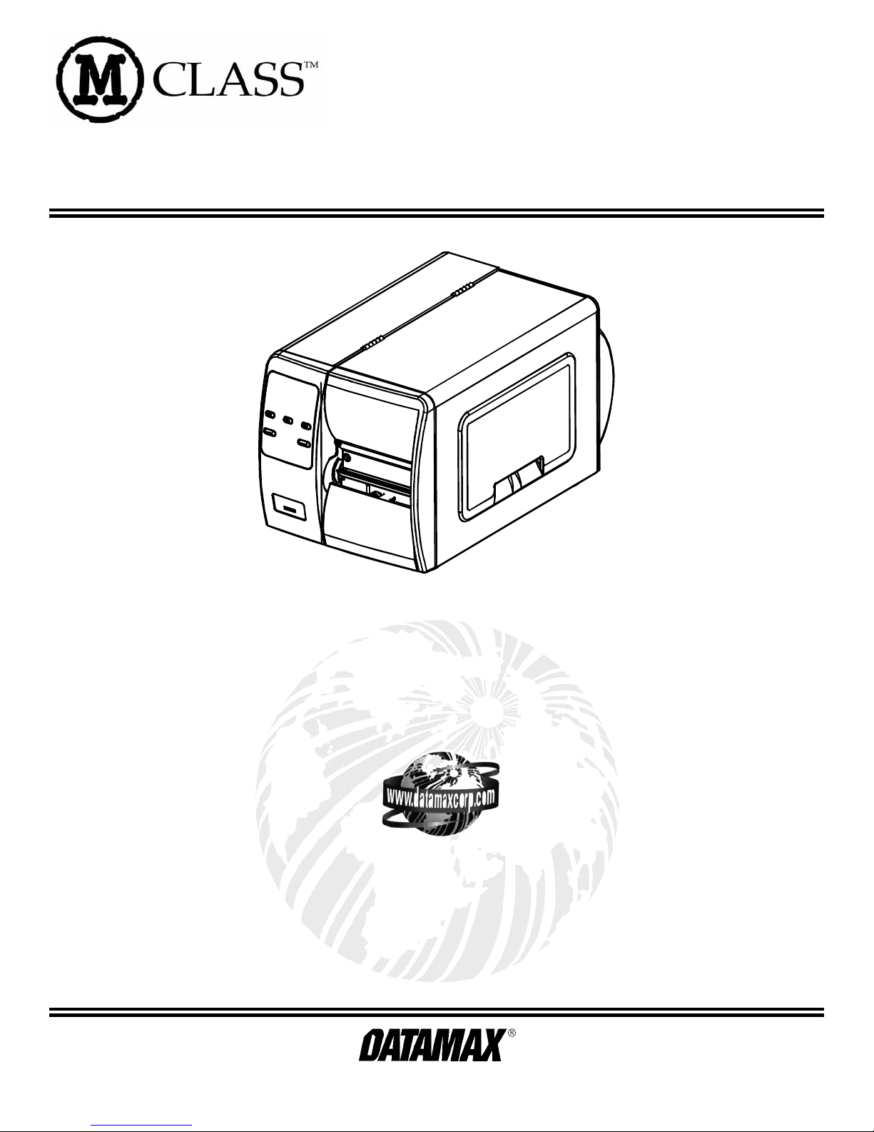
Contents of the Internal Ethernet Print Server Kit (DPO78-2538-01)
This kit contains the following items:
c Internal Ethernet Print Server PCB, P/N 51-2361-00
d S tandoff, P/N 17-3047-01
e R ibbon Cable, P/N 32-2546-01
Follow the steps listed below to install this option.
Note: Only qua lif ied s ervice personnel should ins tall this Op tion.
)
1
2
Tools Required
To install this option you will need a #2 Phillip s head sc rewdriver .
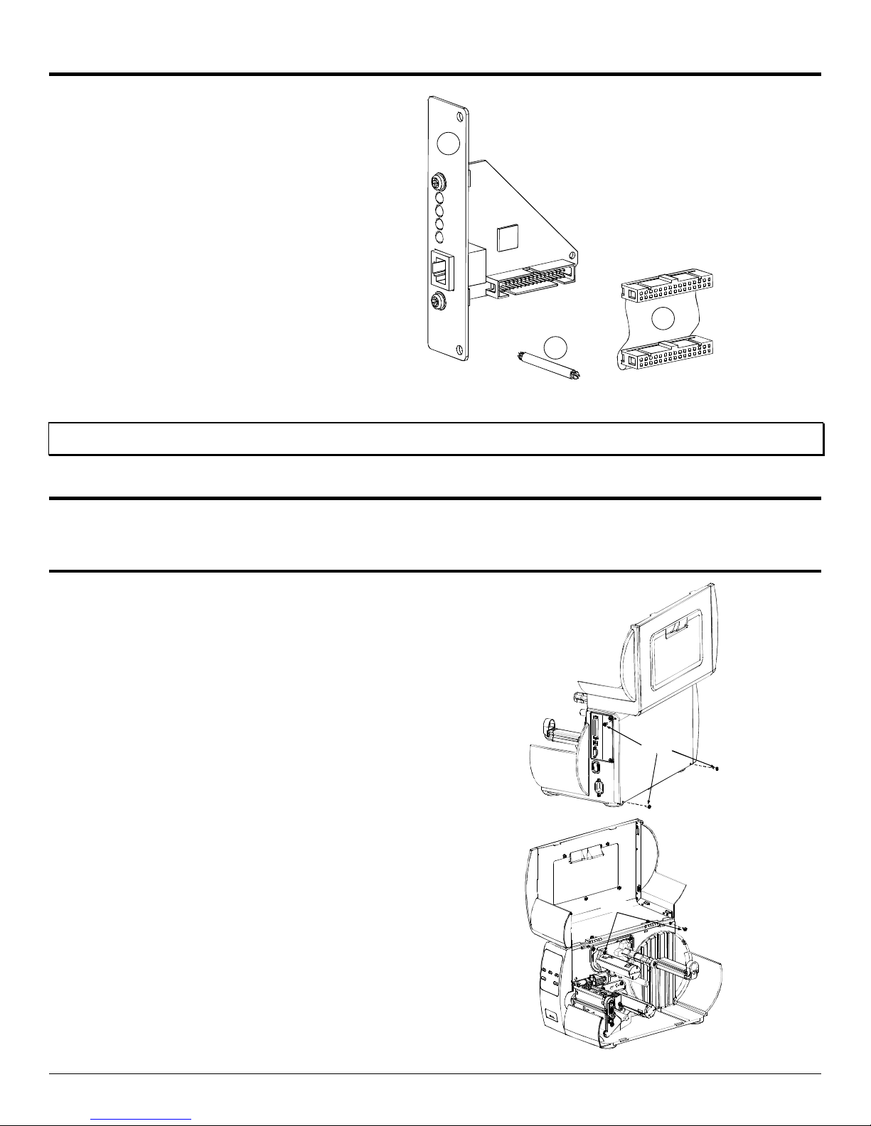
Preparing the Printer
Metal Cover Removal:
1. Turn ‘Off’ the power switch and unplug the printer.
2. Op en t he cover. Remove any inst alled media/ribb on
from the printer.
3. Remove the s ingle Scr ew on the rea r of the printer and
remove the two Scr ews secu ring the side cover.
3
Screws
4. Op en the cover, remove the t wo Screws from the inside
of the printer as shown.
Screws
1
Page 4
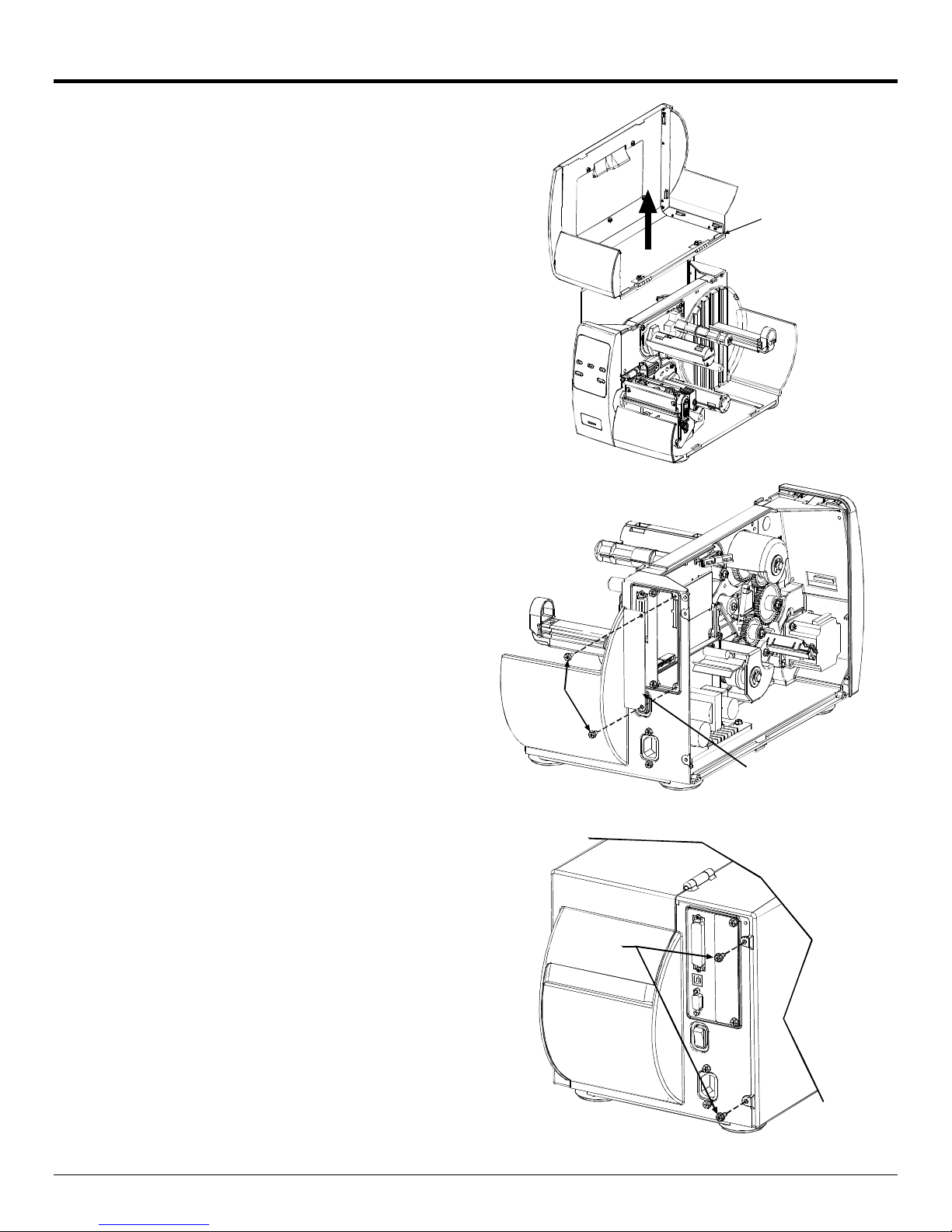
Preparing the Printer (continued)
5. Lift the cover up and off the printer.
6. Remove the two S crews and the Cover Plate fr om t he
rear of the printer.
Cover
Assembly
Plasti c Cover Removal:
1. On the rear of the printer, remove the two Screws
securing the cover.
Screws
Screws
Cover
Plate
2
Page 5
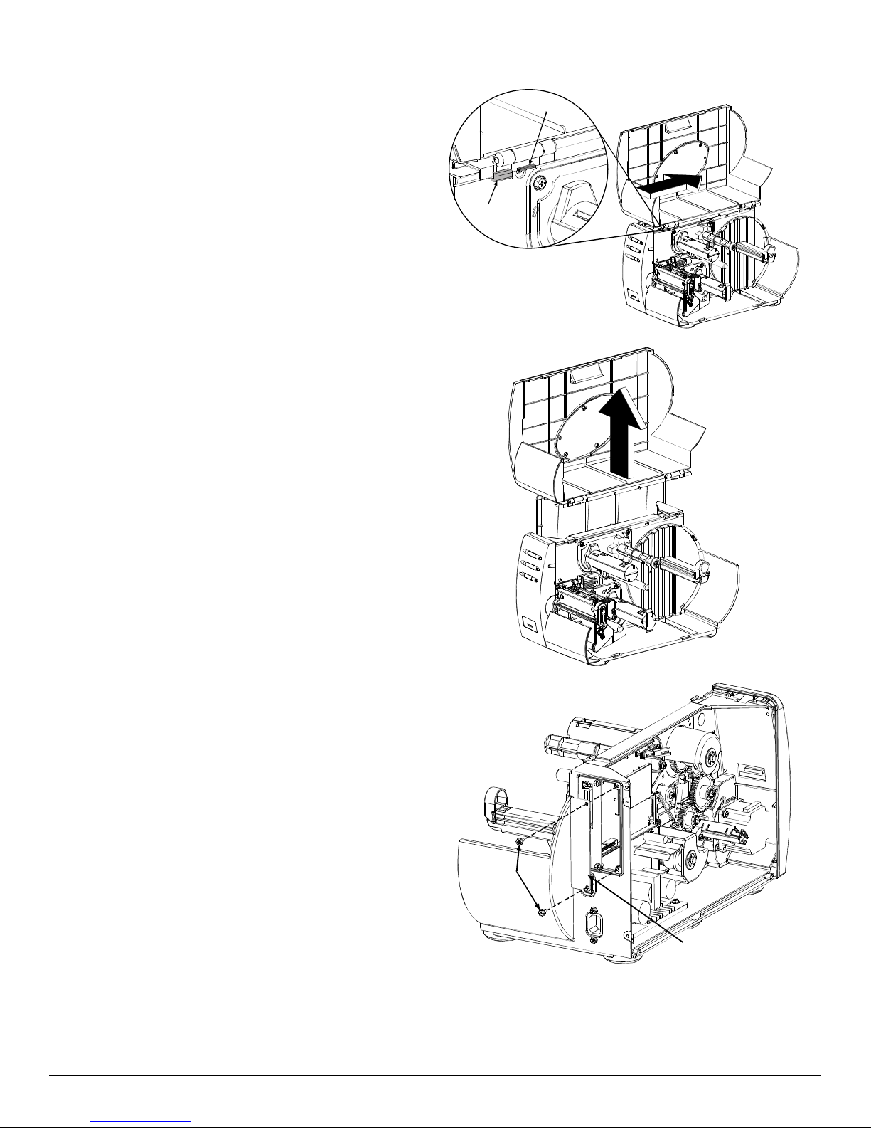
2. Op en the c o v er, sl i d e the co v er to th e rear o f th e pr inter
as shown. Be s ure t he Slide on the cover is clea r of t he
Catch on the frame of the printer.
3. Lift the cover up and off the printer.
Slide
Catch
4. Remove the two S crews and the Cover Plate fr om t he
rear of the printer.
Screws
Cover
Plate
3
Page 6

Installing the Internal Ethernet Print Server Assembly
1. Slid e the Print Server
Assembly into the rear of the
Print Server
Assembly
printer and secure with the two
previou sly removed sc rews.
Screws
2. Install each end of the supplied
Ribbon Cable into its
corresponding c onnec tors on
the pr inter’ s main board and
Print Server Assembly.
Connectors
Standoff
3. Insert the Standoff into the
holes in the printer ’ s main
board a nd Print Server
Assembly.
Ribbon
Cable
4. Re-install the printer’s covers
and associated screws.
Indicators and Connector
10M Indicates a valid 10 -megabit Ether net c onnection is
100M Indicates a valid 100-megabit Ethernet connection is
RX Fla shes when data is being received by the pr intser ver.
TX Flashes when data is being transmitted by the printserver.
present when li t.
present when li t.
10M/100M Ethe r net Conn ect or
10 Meg. Ethernet
Connection Indicator
100 Meg. Ethernet
Connection Indicator
Data Received Indicator
Data Transmit Indicator
RJ-45 Connector
M-Class Ethernet
Print Server
10M
100M
RX
TX
4
Page 7
Setup and Configuration
The Int ernal E thernet Pr int Server can be configured in one of two ways :
> Using ‘ I P Discovery’ (DHCP, BootP, and RARP)
or
> Using a st atic I P set using the p rinter’s f ront panel.
;
Note: The factory def ault has IP Di scovery ‘E nabled’. If you do not wish to use the I P Discov er y function be sure to
set it to ‘Disable’ using the printers f r ont panel before connecting and powering on the pri nter.
Configuration Using IP Disc overy (DHCP, BootP, and RARP)
;
Note: After approximatel y 3 minut es the pr inter will display "IP DISCOVER FAILED" if it was unable to find a DHCP
server. This m essage does not ef fect the operation of the printer and can be cleared fr om the di spl ay by
pressing the
FEED
button.
Once the Ethernet Pr int Sever has been installed and connected, pl ug in the power cord and Ethernet c able then turn the
printer’s power switch ‘On’.
DHCP, B ootP, and RARP are server ser vic es that provide a method for assigning and maintaining IP addresses . T he Print
Server obtains IP i n for mat ion from these services.
The fa ctor y default has I P Disc overy enabled. This enables a ll three (DH CP, BootP , and R ARP) server s ervices, they are
not individu ally selecta ble. The Pr int Server makes I P requests at power -up. If u sing this method of disc overy, aft er the
connection is established p rint a Configura tion Label (see below) f rom the printer to obt ain the IP Addres s and then use it to
install your pr inter p ort and driver to complet e you r set up.
;
Note: Depending upon your server, you may hav e to w ait a m inute or tw o for the assigned IP Address to appear on
the Configuration Label.
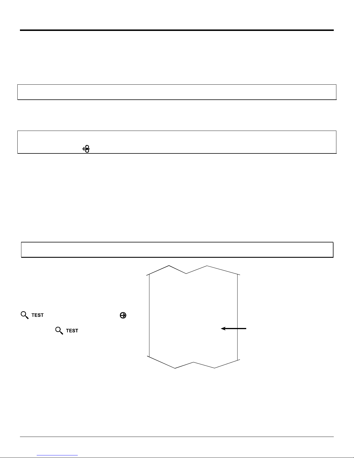
To print a configuration label:
With the printer on, loaded with media (at
least 4 inches wide) and r ibbon (if printing
with thermal transfer media). Press the
bu tt on o n ce, then use the
button scroll to
and press the
‘PRINT CONF IGURATI ON’
button again to print.
FWD
PRINT CONTROL
HEAT
10
PRINT SPEED
8.0 in/sec
FEED SP EED
8.0 in/sec
REVERSE SPEED
4.0 in/sec
ROW OFFSET
00.00 inches
COLUMN OFFSET
00.00 inches
PRESENT DISTANCE
0.00 inches
CUSTOM ADJ US TMENTS:
DARKNESS
32
CONTRAST
32
ROW ADJUST
0 DOTS
COLUMN ADJUST
0 DOTS
PRESENT ADJ UST
64 DOTS
PRINTER OPTIONS
MODULES
A: NOT INSTALLED
B: NOT INSTALLED
D: NOT INS T A L L ED
F: NOT INSTALLED
G: NOT INSTALLED
X: NOT INSTALLED
Y: NOT INSTALLED
Z: NOT INSTALLED
PRESENT SENSOR:
MODE
DISABL ED
RETRACT DELAY
0 X 10mS
COMMUNICATIONS
SERIAL PORT A:
BAUD RA TE
9600
PROTOCOL
BOTH
PARITY
NONE
DATA BITS
8
STOP BITS
1
SERIAL PORT B:
NOT INSTALLED
PARALL EL PORT A:
PORT DIRECTION
UNI-DIRECTIONAL
USB PORT
INSTALLED
NIC ADAPTER:
MAC:00-0d-70-00-00-09
IP ADDRESS
168.24.12.192
SUBNET MASK
255.255.255.255
GATEWAY
168.24.254.254
SNMPTRAP DESTINATION
000.000.000.000
IP DISCOVERY
ENABLED
HOST SETTINGS:
HOST TIMEOUT
10 sec
CONTROL CODES
STANDARD CODES
FEEDBACK CHARACTERS
DISABLED
Assigned IP
Address
Once you ha ve ob tained t he ass igned IP from the configura tion label you ca n then install the p ort and printer driver using
the Windows® ‘Add a Printer Wizard’. S ee section, Installing the Printer Driver and Port in this document.
5
Page 8

Configuration Using a Static I P Address
Once the Ethernet Pr int Sever has b een ins talled, plug in t he p ower cor d, bu t do not c onnect the Ethernet cab l e, then turn the
printer’s power switch ‘On’.
1. Verify the pr inter is in the ‘Rea dy Mode’
2. Press the
MENU
button to enter the printer’s menu.
3. Using the
press the
FWD
button scroll to
but ton.
‘COMMUNICATIONS’ and
4. Using the
the
FWD
but ton.
button scroll to
‘NIC ADAPTER’ and press
5. Using the
the
FWD
but ton.
button scroll to
‘IP DISCOVERY’ and press
6. Using the
FWD
button scroll to
‘DISABLED’ and press the
but ton.
XFE!21;27B!13KVM3114!
SFBEZ!
NFOV!NPEF!
NFEJB!TFUUJOHT!
NFOV!NPEF!
DPNNVOJDBUJPOT!
DPNNVOJDBUJPOT!
OJD!BEBQUFS!
OJD!BEBQUFS!
JQ!EJTDPWFSZ!
JQ!EJTDPWFSZ!
+EJTBCMFE!
7. Press the button once to return to the ‘NIC
ADAPTER’
menu level . Then use the
‘IP ADDRESS’ and pr es s the but ton.
FWD
button scroll to
OJD!BEBQUFS!
JQ!BEESFTT!
8. Use the
FWD
flashing valu e. Press the
field . On ce all fi el d s a re c o rrect pres s t he
once. T he value will au tomatic ally be s aved.
You can then u se t he
and ‘GATEWAY’ menu items and s et those va lues in the
same mann e r as the
;
Note: When the menu item ‘IP DISCOVERY’ is set to enabled you will not b e a ble to change the v alues for t he “IP ADDRESS’,
‘SUBNET MASK’, or ‘GATEW AY’ menu items. The values displayed are for reference only and will b e c o me a c tiv e o n c e
‘IP DISCOVERY’ set to disabled.
9. Once you have the p roper address es set, press t he
but ton rep eatily until you have exited the printer’s menu.
REV
and
buttons to increment/decremnt the
FWD
to scroll to the ‘SUBNET MASK
‘IP ADDRESS’ was set.
button to move to the next
but ton
JQ!BEESFTT!
+2:3/111/111/2:3!
TVCOFU!NBTL!
+111/111/111/111!
HBUFXBZ!
+111/111/111/111!
XFE!21;27B!13KVM3114!
SFBEZ!
Turn OFF the printer and then back ON.
Once you have entered your IP settings int o the pr inter you c an then ins tall the por t and p rint er driver using the Windows®
‘Add a Printer Wizard’. S ee section, Installing the Printer Driver and Port in this document.
6
Page 9

Using the HTML Pages
The p r int er ha s r esident HT M L (Web ) p a ges t ha t a llow conf igura tion of networ k a nd p r int er set t ings a s well a s per f or ming
status queries and diagnostic tests. To configure the Print Server and other internal printer settings you can access the
printer via HTML pages using any Web browser.
1. In you r Web browser, choose File -> Open.
2. Ent er the IP address of the Print Server and press Enter . (The defau l t IP Address is:
192.0.0.192)
;
Note: Consult with your system administrator for all necessary address, pri nter, and protoc ol information. T o c hange
these settings you will be asked for an authentication password. Type sysadm and cl ick “Apply”.
Next you sh ould see th e Print Server’ s Unit Inf ormat ion page:
7
Page 10

Network Status
TCP/IP Configuration
8
Page 11

System Settings, Media Settings, and Print Control
Many of the pr inter' s inter nal menu settings c an be cont rolled from the following next six s c reens. This allows the user to
adjust many of the pr inter' s settings remotely without using the pr inter's fr ont panel. F or more informat ion on the function of
these settings see th e M-Class Operator’s Manual.
9
Page 12

Printer Options, Communications, and Diagnostics
10
Page 13

Network Print Options
Reset Network Par ameters
Change Password
11
Page 14

Installing the Printer Driver and Port
Windows 95/98 Driver and Port Installation
1
Start the Windows
“Add P rin ter Wizzard”.
The following screen
should appear, click
‘Next>’.
2
Make sure that ‘Local
Printer’ is selected and
then click ‘Next’.
3
Click on ‘Have Disk’.
5
Browse to the
“\DRIVERS\Seagull”
folder on the CD-ROM,
make sure the file
“Datamax for 95, 98,
me, 2000, and xp.inf” is
selected and click ‘OK’.
7
Select the ‘M-4208’
printer from the list and
then click ‘Next’.
4
Insert the Accessories
CD-Rom and click
‘Browse’.
6
Click ‘OK’.
8
Your computer will
now copy the necessary
files from the CDROM.
9
When prompted to
choose a port, select
‘FILE’ for now and
click ‘Next’. You will
set up the network port
from the printer
properties later.
10
Name your printer in
the ‘Printer name:’
field. Next select
whether or not to set
this printer as your
default printer. Then
Click ‘Finish’.
12
Page 15

11
From the Windows
desktop click ‘Start’ /
‘Settings’ / ‘Printers’.
12
Once the Printers
window opens, rightclick on the printer icon
and select ‘Properties’
from the drop down
menu.
13
Click on the ‘Details’
tab and then click ‘Add
Port’.
15
In the ‘Name or IP
Address:’ field enter the
IP address of your
printer. The ‘Port
Number’ and ‘Port
Name’ fields do not
need to be changed.
When finished click
“OK’
14
In the ‘Add Port’
window, Select ‘Other’
and “Seagull Scientific
Port” and then click
‘OK’.
16
Click ‘Apply’ and then
click ‘OK’.
The driver and port
installation is now
complete. The printer
can be selected through
any Window’s
application.
13
Page 16

Windows NT 4.0 Driver and Port Installation
1
Start the Windows
“Add P rin ter Wizzard”.
Make sure that
Computer’
and then click ‘Next’.
‘My
is selected
2
Click ‘Add Port’.
3
Double-click ‘LPR
Port’.
5
Click ‘Close’
7
Click on ‘Have Disk’.
4
In the top field enter
the IP address of your
printer. In the bottom
field enter PORT1.
When finished click
“OK’.
6
Click ‘Next’.
8
Insert the Accessories
CD-Rom and click
‘Browse’.
9
Browse to the
“\DRIVERS\Seagull\Nt
4\” folder on the CDROM, make sure the
file “Datamax for nt 4.0
only…” is selected and
click ‘Open’.
10
Click ‘OK’.
14
Page 17

11
Select the ‘M-4208’
printer from the list and
then click ‘Next’.
12
Name your printer in
the ‘Printer name:’
field. Next select
whether or not to set
this printer as your
default printer. Then
Click ‘Next’.
13
Select whether or not to
share this printer on
your network. Then
Click ‘Next’.
15
Your computer will
now copy the necessary
files from the CDROM.
The driver and port
installation is now
complete. The printer
can be selected through
any Window’s
application.
14
Select ‘No’ then Click
‘Finish’.
15
Page 18

Windows 2000 Driver and Port Install at ion
1
Start the Windows
“Add P rin ter Wizzard”.
The following screen
should appear, click
‘Next>’.
3
Select on ‘Create a new
port:’ and then select
‘Standard TCP/IP Port’
from the drop down
menu. Click ‘Next’
2
Make sure that ‘Local
Printer’ is selected and
then click ‘Next’.
4
Click ‘Next’.
5
In the ‘Printer Name or
IP Address:’ field enter
the IP address of your
printer. The ‘Port
Name’ field does not
need to be changed.
When finished click
‘Next’.
7
Confirm your settings
and then click ‘Finish’.
6
Make sure ‘Standard’
is selected and then
click ‘Next’.
8
Click on ‘Have Disk’.
16
Page 19

9
Insert the Accessories
CD-Rom and click
‘Browse’.
10
Browse to the
“\DRIVERS\Seagull”
folder on the CD-ROM,
make sure the file
“Datamax for 95, 98,
me, 2000, and xp.inf”
is selected and click
‘OK’.
11
Click ‘OK’.
13
Name your printer in
the ‘Printer name:’
field. Next select
whether or not to set
this printer as your
default printer. Then
Click ‘Next’.
15
Select ‘No’ then Click
‘Next’.
12
Select the ‘M-4208’
printer from the list and
then click ‘Next’.
14
Select whether or not to
share this printer on
your network. Then
Click ‘Next’
16
Confirm your settings
and then click ‘Finish’.
17
If prompted with the
"Digital Signature Not
Found" window, click
‘Yes’ to continue
installation.
18
Your computer will
now copy the necessary
files from the CDROM.
The driver and port
installation is now
complete. The printer
can be selected through
any Window’s
application.
17
Page 20

Windows XP Driver and Port Installation
1
Start the Windows
“Add P rin ter Wizzard”
The following screen
should appear, click
‘Next>’.
2
Make sure that ‘Local
Printer’ is selected and
then click ‘Next’.
3
Select on ‘Create a new
port:’ and then select
‘Standard TCP/IP Port’
from the drop down
menu. Click ‘Next’
5
In the ‘Printer Name or
IP Address:’ field enter
the IP address of your
printer. The ‘Port
Name’ field does not
need to be changed.
When finished click
“Next’.
7
Confirm your settings
and then click ‘Finish’.
4
Click ‘Next’.
6
Make sure ‘Standard’
is selected and then
click ‘Next’.
8
Click on ‘Have Disk’.
18
Page 21

9
Insert the Accessories
CD-Rom and click
‘Browse’.
11
Click ‘OK’.
10
Browse to the
“\DRIVERS\Seagull”
folder on the CD-ROM,
make sure the file
“Datamax for 95, 98,
me, 2000, and xp.inf”
is selected and click
‘OK’.
12
Select the ‘M-4208’
printer from the list
and then click ‘Next’.
13
Name your printer in
the ‘Printer name:’
field. Next select
whether or not to set
this printer as your
default printer. Then
Click ‘Next’.
15
Select ‘No’ then Click
‘Next’.
17
If prompted with the
"Digital Signature Not
Found" window, click
‘Yes’ to continue
installation.
14
Select whether or not to
share this printer on
your network. Then
Click ‘Next’
16
Confirm your settings
and then click ‘Finish’.
18
Your c o mputer will now
copy th e necess ary files
from the CD-ROM.
The driver and port
installa tion is now
complete. The printer ca n
be selected through any
Window’s application.
19
Page 22

20
 Loading...