

Page 1
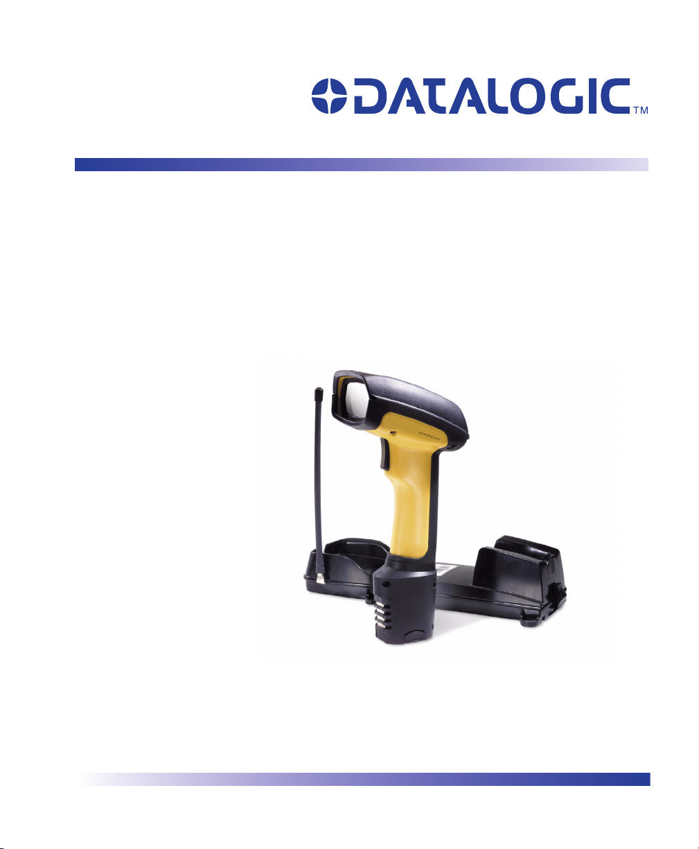
PowerScan® RF
SR/HD/LR/XLR
Handheld Bar Code Scanner
Handstrichcodeleser
Douchette Laser
Lettore portatile di codici a barre
Benutzerhandbuch
Guide de L’utilisateur
Manuale d’Istruzioni
User’s Guide
Page 2

Datalogic Scanning, Inc.
959 Terry Street
Eugene, Oregon 97402
Telephone: (541) 683-5700
Fax: (541) 345-7140
An Unpublished Work - All rights reserved. No part of the contents of this documentation or the procedures
described therein may be reproduced or transmitted in any form or by any means without prior written permission of
Datalogic Scanning, Inc. or its subsidiaries or affiliates ("Datalogic" or “Datalogic Scanning”). Owners of Datalogic
products are hereby granted a non-exclusive, revocable license to reproduce and transmit this documentation for
the purchaser's own internal business purposes. Purchaser shall not remove or alter any proprietary notices,
including copyright notices, contained in this documentation and shall ensure that all notices appear on any reproductions of the documentation.
Should future revisions of this manual be published, you can acquire printed versions by contacting your Datalogic
representative. Electronic versions may either be downloadable from the Datalogic website (www.scanning.datalogic.com) or provided on appropriate media. If you visit our website and would like to make comments or suggestions about this or other Datalogic publications, please let us know via the "Contact Datalogic" page.
Disclaimer
Datalogic has taken reasonable measures to provide information in this manual that is complete and accurate,
however, Datalogic reserves the right to change any specification at any time without prior notice.
Datalogic is a registered trademark of Datalogic S.p.A. and the Datalogic logo is a trademark of Datalogic S.p.A. all
licensed to Datalogic Scanning, Inc. All other trademarks and trade names referred to herein are property of their
respective owners.
This product may be covered by one or more of the following patents: 4603262 • 4639606 • 4652750 • 4672215 • 4699447 • 4709369 • 4749879
• 4786798 • 4792666 • 4794240 • 4798943 • 4799164 • 4820911 • 4845349 • 4861972 • 4861973 • 4866257 • 4868836 • 4879456 • 4939355 •
4939356 • 4943127 • 4963719 • 4971176 • 4971177 • 4991692 • 5001406 • 5015831 • 5019697 • 5019698 • 5086879 • 5115120 • 5144118 •
5146463 • 5179270 • 5198649 • 5200597 • 5202784 • 5208449 • 5210397 • 5212371 • 5212372 • 5214270 • 5229590 • 5231293 • 5232185 •
5233169 • 5235168 • 5237161 • 5237162 • 5239165 • 5247161 • 5256864 • 5258604 • 5258699 • 5260554 • 5274219 • 5296689 • 5298728 •
5311000 • 5327451 • 5329103 • 5330370 • 5347113 • 5347121 • 5371361 • 5382783 • 5386105 • 5389917 • 5410108 • 5420410 • 5422472 •
5426507 • 5438187 • 5440110 • 5440111 • 5446271 • 5446749 • 5448050 • 5463211 • 5475206 • 5475207 • 5479011 • 5481098 • 5491328 •
5493108 • 5504350 • 5508505 • 5512740 • 5541397 • 5552593 • 5557095 • 5563402 • 5565668 • 5576531 • 5581707 • 5594231 • 5594441 •
5598070 • 5602376 • 5608201 • 5608399 • 5612529 • 5629510 • 5635699 • 5641958 • 5646391 • 5661435 • 5664231 • 5666045 • 5671374 •
5675138 • 5682028 • 5686716 • 5696370 • 5703347 • 5705802 • 5714750 • 5717194 • 5723852 • 5750976 • 5767502 • 5770847 • 5786581 •
5786585 • 5787103 • 5789732 • 5796222 • 5804809 • 5814803 • 5814804 • 5821721 • 5822343 • 5825009 • 5834708 • 5834750 • 5837983 •
5837988 • 5852286 • 5864129 • 5869827 • 5874722 • 5883370 • 5905249 • 5907147 • 5923023 • 5925868 • 5929421 • 5945670 • 5959284 •
5962838 • 5979769 • 6000619 • 6006991 • 6012639 • 6016135 • 6024284 • 6041374 • 6042012 • 6045044 • 6047889 • 6047894 • 6056198 •
6065676 • 6069696 • 6073849 • 6073851 • 6094288 • 6112993 • 6129279 • 6129282 • 6134039 • 6142376 • 6152368 • 6152372 • 6155488 •
6166375 • 6169614 • 6173894 • 6176429 • 6188500 • 6189784 • 6213397 • 6223986 • 6230975 • 6230976 • 6237852 • 6244510 • 6259545 •
6260763 • 6266175 • 6273336 • 6276605 • 6279829 • 6290134 • 6290135 • 6293467 • 6303927 • 6311895 • 6318634 • 6328216 • 6332576 •
6332577 • 6343741 • 6454168 • 6478224 • 6568598 • 6578765 • 6705527 • 6974084 • 6991169 •7051940 • AU703547 • D312631 • D313590 •
D320011 • D320012 • D323492 • D330707 • D330708 • D349109 • D350127 • D350735 • D351149 • D351150 • D352936 • D352937 • D352938
• D352939 • D358588 • D361565 • D372234 • D374630 • D374869 • D375493 • D376357 • D377345 • D377346 • D377347 • D377348 •
D388075 • D446524 • EP0256296 • EP0260155 • EP0260156 • EP0295936 • EP0325469 • EP0349770 • EP0368254 • EP0442215 •
EP0498366 • EP0531645 • EP0663643 • EP0698251 • GB2252333 • GB2284086 • GB2301691 • GB2304954 • GB2307093 • GB2308267 •
GB2308678 • GB2319103 • GB2333163 • GB2343079 • GB2344486 • GB2345568 • GB2354340 • ISR107546 • ISR118507 • ISR118508 •
JP1962823 • JP1971216 • JP2513442 • JP2732459 • JP2829331 • JP2953593 • JP2964278 • MEX185552 • MEX187245 • RE37166 • Other
Patents Pending
Page 3

Datalogic Scanning, Inc.
POWERSCAN® END USER LICENSE AGREEMENT
Notice to End User: The Datalogic Product you have acquired contains embedded Software, which is integral to the product’s operation. This
Software is being provided to you under license, subject to the terms and conditions of this Agreement. If you use the Datalogic Product, you will
be deemed to have accepted the terms and conditions of this Agreement. If you do not intend to be bound to the terms of this Agreement, Datalogic is not willing to license the Software to you, you may not use the Datalogic Product or the Software, and you must contact the party from
whom you acquired the Datalogic Product for instructions.
This End User Software License Agreement (“Agreement”) is a legally binding agreement governing the licensing of the Software and Documentation by Datalogic, Scanning Holdings, Inc. and its wholly owned subsidiaries and affiliates (“Datalogic”) to the entity or person who has purchased or otherwise acquired
a Datalogic Product (“End User”). For purposes of this Agreement, any software that is associated with a separate end-user license agreement is licensed to
you under the terms of that license agreement. Datalogic and End User hereby agree as follows:
1. Definitions.
1.1 "Documentation" means materials such as user’s guides, program reference guides, quick reference guides, manuals, or similar materials associated
with or related to the Datalogic Product, whether in printed, “online”, or other form.
1.2 "Proprietary Information" means: (a) source code, object code, software, documentation, and any related internal design, system design, data base
design, algorithms, technology, technical data or information, implementation techniques, and trade secrets related to the Software, (b) any other trade
secrets marked appropriately or identified as proprietary or confidential, and (c) any information that End User, under the circumstances, should recognize as confidential. Proprietary Information does not include any information that the receiving party can establish was (1) in the public domain, (2)
already in the receiving party’s possession or rightfully known prior to receipt, (3) rightfully learned from a third party not in violation of any other's proprietary rights, or (4) independently developed without access to Proprietary Information.
1.3 “Datalogic Product” means the Datalogic Powerscan® series, Powerscan® Imager series, Powerscan® EP series, Powerscan® LR series, Powerscan
HD series, and/or Powerscan RF® series scanner and/or scanner/scale product, including all embedded Software in and all Documentation related to
such product, which has been purchased or otherwise acquired by End User, whether obtained directly or indirectly from Datalogic.
1.4 "Software" means any software or computer programs of Datalogic or its third party licensors in machine readable form which is embedded in the Datalogic Product, whether obtained directly or indirectly from Datalogic, including any replacement, update, upgrade, enhancement or modification.
2. Scope Of License Granted.
2.1 Datalogic grants to End User a non-exclusive, non-transferable, perpetual license to use the Software, solely on the Datalogic Product in which it is
embedded (“designated Datalogic Product”), in machine-readable form only, solely for End User's internal business purposes. This Agreement does
not convey ownership of the Software to End User. Title to the Software shall be and remain with Datalogic or the third party from whom Datalogic has
obtained a licensed right. As used in this Agreement, the term “purchase” or its equivalents when applied to the Software shall mean “acquire under
license.” End User is not entitled to receipt or use of the source code to any Software.
2.2 End User shall not copy, modify, decompile, disassemble, reverse engineer, or otherwise reproduce or remanufacture the Software, whether modified
or unmodified, nor sell, assign, sublicense, distribute, lend, rent, give, or otherwise transfer the Software to any other person or organization, for purposes other than as expressly provided in this Agreement, without Datalogic’s prior written consent.
3. Transfers, Support.
3.1 Any copying, installing, reproduction, remanufacture, reverse engineering, electronic transfer, or other use of the Software on other than the designated Datalogic Product will be a material breach of this Agreement. However, Datalogic may elect not to terminate this Agreement or the granted
licenses, but instead may elect to notify End User that End User is deemed to have ordered and accepted a license for each breaching use. End User
shall pay Datalogic the applicable list price for such licenses as of the date of such breach.
3.2 End User shall not sell, assign, sublicense, distribute, lend, rent, give, or otherwise transfer the Datalogic Product to any third party unless such third
party agrees with Datalogic in writing to be bound by the terms and conditions of this Agreement. Any such transfer of the Datalogic Product absent
such agreement shall be null and void.
3.3 End User may obtain support for Software from Datalogic at Datalogic’s standard support fees and under Datalogic’s standard support terms and conditions in effect at the time the support is requested.
4. Intellectual Property.
End User acknowledges that the Software constitutes valuable trade secrets of Datalogic or Datalogic’s third party licensors and that the Software is protected by intellectual property laws and treaties. The license set forth in this Agreement does not transfer to End User any ownership of Datalogic’s or its third
party licensors' copyrights, patents, trademarks, service marks, trade secrets, or other intellectual property rights and End User shall have no right to commence any legal actions to obtain such rights. End User shall not remove, modify, or take any other action that would obscure any copyright, trademark,
patent marking, or other intellectual property notices contained in or on the Datalogic Product.
5. Proprietary Information.
5.1 End User acknowledges that Proprietary Information is the confidential, proprietary, and trade secret property of Datalogic and Datalogic’s third party
licensors and End User acquires no right or interest in any Proprietary Information.
5.2 End User shall not disclose, provide, or otherwise make available the Proprietary Information of Datalogic or its third party licensors to any person
other than End User’s authorized employees or agents who are under confidentiality agreement, and End User shall not use the Proprietary Information other than in conjunction with use of the Datalogic Product exclusively for End User’s internal business purposes. End User shall take steps to
protect the Proprietary Information no less securely than if it were End User's own intellectual property.
5.3 The provisions of this Proprietary Information Section shall survive and continue for five (5) years after the termination of this Agreement.
6. Limited Warranty.
6.1 Datalogic warrants that, under normal use and operation, the Datalogic Product will conform substantially to the applicable Documentation for the
period specified in the Documentation. During this period, for all reproducible nonconformities for which Datalogic has been given written notice, Datalogic will use commercially reasonable efforts to remedy nonconformities verified by Datalogic. End User agrees to supply Datalogic with all reasonably
requested information and assistance necessary to help Datalogic in remedying such nonconformities. For all defects reported to Datalogic within the
®
i PowerScan
®
RF Scanner
Page 4

warranty period, Datalogic’s liability is limited to providing End User with one copy of corrections or responding to End User's problem reports according to Datalogic's standard assistance practices. Datalogic does not warrant that the product will meet End User's requirements or that use of the product will be uninterrupted or error free, or that Datalogic's remedial efforts will correct any nonconformance. This limited warranty does not cover any
product that have been subjected to damage or abuse, whether intentionally, accidentally, or by neglect, or to unauthorized repair or unauthorized
installation, and shall be void if End User modifies the product, uses the product in any manner other than as established in the Documentation, or if
End User breaches any of the provisions of this Agreement.
6.2 EXCEPT AS PROVIDED IN THIS AGREEMENT, THE DATALOGIC PRODUCT IS PROVIDED “AS IS” AND DATALOGIC MAKES NO WARRANTIES
OF ANY KIND, EXPRESS OR IMPLIED, WRITTEN OR ORAL, WITH RESPECT TO THE PRODUCT, AND SPECIFICALLY DISCLAIMS THE
IMPLIED WARRANTIES OF MERCHANTABILITY AND FITNESS FOR A PARTICULAR PURPOSE.
7. Infringement.
7.1 Datalogic will defend End User against any claim in a lawsuit that the Datalogic Product furnished hereunder infringe a United States patent or copyright of a third party and Datalogic will pay any damages finally awarded against End User by a court of competent jurisdiction that are attributable to
such claim or will pay End User’s part of any settlement that is attributable to such claim, provided, that 1) End User notifies Datalogic promptly in writing of the claim, 2) Datalogic controls the defense or settlement of the claim, and 3) End User cooperates fully with Datalogic in such defense or settlement. All notices of a claim should be sent to Datalogic Scanning, Inc., Legal Department, 111 SW Fifth Ave. Suite 4100, Portland, OR 97204-3644.
7.2 In the defense or settlement of any such claim, Datalogic may, at its option, 1) procure for End User the right to continue using the Datalogic Product,
2) modify the Datalogic Product so that it becomes non-infringing, 3) replace the Datalogic Product with an equivalent product not subject to such
claim, or 4) provide End User an opportunity to return the Datalogic Product and receive a refund of the purchase price paid, less a reasonable allowance for use.
7.3 Datalogic shall have no liability to End User for claims of infringement based upon 1) the use of any Datalogic Product in combination with any product
which Datalogic has not either furnished or authorized for use with such Datalogic Product 2) the use of any Datalogic Product designed, manufactured, or modified to the specifications of End User, or 3) End User’s modification of the Datalogic Product without written authorization from Datalogic.
7.4 THE FOREGOING STATES DATALOGIC’S COMPLETE AND ENTIRE OBLIGATION CONCERNING CLAIMS OF PATENT, COPYRIGHT, OR OTHER
INTELLECTUAL PROPERTY INFRINGEMENT, CANCELS AND SUPERCEDES ANY PRIOR AGREEMENTS, WHETHER ORAL OR WRITTEN,
BETWEEN THE PARTIES CONCERNING SUCH CLAIMS, AND WILL NOT BE MODIFIED OR AMENDED BY ANY PAST, CONTEMPORANEOUS,
OR FUTURE AGREEMENTS OR DEALINGS BETWEEN THE PARTIES, WHETHER ORAL OR WRITTEN, EXCEPT AS SET FORTH IN A FUTURE
WRITING SIGNED BY BOTH PARTIES.
8. Limitation Of Liability.
EXCEPT AS PROVIDED IN SECTION 7, DATALOGIC SHALL NOT BE LIABLE FOR ANY CLAIMS AGAINST END USER BY ANY OTHER PARTY. IN NO
EVENT SHALL DATALOGIC'S LIABILITY FOR DAMAGES, IF ANY, WHETHER BASED UPON CONTRACT, TORT (INCLUDING NEGLIGENCE), PRODUCT LIABILITY, STRICT LIABILITY, WARRANTY, OR ANY OTHER BASIS, EXCEED THE PRICE OR FEE PAID BY END USER FOR THE DATALOGIC
PRODUCT. UNDER NO CIRCUMSTANCES SHALL DATALOGIC BE LIABLE TO END USER OR ANY THIRD PARTY FOR LOST PROFITS, LOST DATA,
INTERRUPTION OF BUSINESS OR SERVICE, OR FOR ANY OTHER SPECIAL, CONSEQUENTIAL, CONTINGENT, INDIRECT, INCIDENTAL, PUNITIVE,
EXEMPLARY, OR OTHER SIMILAR DAMAGES, EVEN IF DATALOGIC HAS BEEN ADVISED OF THE POSSIBILITY OF SUCH DAMAGES.
9. Government Restricted Rights; International Use.
9.1 Use, duplication, or disclosure of the Software by the U.S. Government is subject to the restrictions for computer software developed at private
expense as set forth in the U.S. Federal Acquisition Regulations at FAR 52.227-14(g), or 52.227-19 or in the Rights in Technical Data and Computer
Software clause at DFARS 252.227-7013(c)(1)(ii), whichever is applicable.
9.2 If End User is using the Datalogic Product outside of the United States, End User must comply with the applicable local laws of the country in which the
Datalogic Product is used, with U.S. export control laws, and with the English language version of this Agreement. The provisions of the “United
Nations Convention on International Sale of Goods” shall not apply to this Agreement.
10. Termination.
10.1 Either party may terminate this Agreement or any license granted under this Agreement at any time upon written notice if the other party breaches any
provision of this Agreement.
10.2 Upon termination of this Agreement, End User immediately shall cease using any non-embedded software and shall return to Datalogic or destroy all
non-embedded software covered by this Agreement, and shall furnish Datalogic with a certificate of compliance with this provision signed by an officer
or authorized representative of End User. For embedded software, End User agrees to sign a waiver prepared by Datalogic concerning further use of
the embedded Software. End User’s resumed or continued use of the embedded Software after termination shall constitute End User’s agreement to
be bound by the terms and conditions of this Agreement for such use.
11. General Provisions.
11.1 Entire Agreement; Amendment. This document contains the entire agreement between the parties relating to the licensing of the Software and supersedes all prior or contemporaneous agreements, written or oral, between the parties concerning the licensing of the Software. This Agreement may not
be changed, amended, or modified except by written document signed by Datalogic.
11.2 Notice
11.3 Waiver. A party’s failure to enforce any of the terms and conditions of this Agreement shall not prevent the party’s later enforcement of such terms and
11.4 Governing Law
. All notices required or authorized under this Agreement shall be given in writing, and shall be effective when received, with evidence of receipt.
Notices to Datalogic shall be sent to the attention of Contract Administration, Datalogic Scanning Inc., 959 Terry Street, Eugene, OR 97402, or such
other address as may be specified by Datalogic in writing.
conditions.
State of Oregon U.S.A, without regard to the rules governing conflicts of law. The state or federal courts of the State of Oregon located in either Multnomah or Lane counties shall have exclusive jurisdiction over all matters regarding this Agreement, except that Datalogic shall have the right, at its
absolute discretion, to initiate proceedings in the courts of any other state, country, or territory in which End User resides, or in which any of End User's
assets are located.
; Venue:This Agreement and the rights of the parties hereunder shall be governed by and construed in accordance with the laws of the
11.5 Attorneys’ Fees. In the event an action is brought to enforce the terms and conditions of this Agreement, the prevailing party shall be entitled to reasonable attorneys’ fees, both at trial and on appeal.
- END -
User’s Guide ii
Page 5

Standard Warranty
Datalogic warrants to Customer that Datalogic's products will be free from defects in materials and workmanship for a period of three years from product shipment.
In order to obtain service under this Warranty, Customer must notify Datalogic of the claimed defect before the expiration of the Warranty period and obtain
from Datalogic a return authorization number for return of the product to designated Datalogic service center. If Datalogic determines Customer’s claim is
valid, Datalogic will repair or replace product without additional charge for parts and labor. Customer shall be responsible for packaging and shipping the
product to the designated Datalogic service center, with shipping charges prepaid. Datalogic shall pay for the return of the product to Customer if the shipment is to a location within the country in which the Datalogic service center is located. Customer shall be responsible for paying all shipping charges, duties,
taxes, and any other charges for products returned to any other locations.
Warranty is subject to the limitations and exclusions set forth below. Warranty set forth above is in lieu of any other warranties, expressed or implied, including
merchantability and fitness.
Exclusions
Warranty coverage shall not apply to any claimed defect, failure or damage which Datalogic determines was caused by: improper use of product; failure to
provide product maintenance, including but not limited to cleaning of the scan windows in accordance with product manual; installation or service of product
by other than Datalogic representatives; use of product with any other instrument, equipment or apparatus; modification or alteration of product. External
cables and replacement of scan windows due to scratching, stains or other degradation will not be covered under the Warranty. Products returned for service
must be accompanied by the original external power supplies for performance of service.
Limitations of Liability
Datalogic repair or replacement of defective product as set forth above is the customer's sole and exclusive remedy on account of claims of breach of warranty or product defect. Under no circumstances will Datalogic be liable to customer or any third party for any lost profits, or any incidental, consequential indirect, special or contingent damages regardless of whether Datalogic had advance notice of the possibility of such damages.
Assignment
Customer may not assign or otherwise transfer its rights or obligations under Warranty except to a purchaser or transferee of product. No attempted assign-
ment or transfer in violation of this provision shall be valid or binding upon Datalogic.
Risk of Loss
Customer shall bear risk of loss or damage for product in transit to Datalogic. Datalogic shall assume risk of loss or damage for product in Datalogic’s possession or product being returned to Customer by Datalogic, except such loss or damage as may be caused by the negligence of Customer, its agents or employees. In the absence of specific written instructions for the return of product to Customer, Datalogic will select the carrier, but Datalogic shall not thereby
assume any liability in connection with the return shipment.
iii PowerScan
®
RF Scanner
Page 6

NOTES
User’s Guide iv
Page 7

MASTER CONTENTS
Table of Contents ...........................................................................1
Deutsches Inhaltsverzeichnis .......................................................29
Français Sommaire ......................................................................59
Italiano Indice ...............................................................................87
User’s Guide i
Page 8

ii PowerScan
®
RF Scanner
Page 9

TABLE OF CONTENTS
Unpack and Inspect Your Scanner ................................................................................1
References ....................................................................................................................1
Quick Start Instructions .................................................................................................1
Installing the Battery ...............................................................................................2
Verifying Scanner Operation ...................................................................................3
Power Supply ..........................................................................................................3
Connecting the Base Station to the Host Terminal .................................................3
Linking the Scanner to a Base Station ....................................................................5
Verifying Scanner-to-Base Station Communications ..............................................7
Using the PowerScan RF System .................................................................................8
Battery Charging and Maintenance ........................................................................8
Tips for Extending Battery Life ................................................................................9
Disposing of Batteries ...........................................................................................10
Four Station Charger ............................................................................................10
How to Scan ................................................................................................................11
Depth of Field ........................................................................................................12
LED and Beeper Indications ........................................................................................16
Active Symbologies ...............................................................................................19
Enhanced Scanning for Hard-to-Read Bar Codes ................................................20
Laser Cautions ............................................................................................................21
Radio Frequency Interference .....................................................................................22
Maintenance ................................................................................................................23
Troubleshooting ...........................................................................................................24
Sample Bar Codes ......................................................................................................25
User’s Guide 1
Page 10

2 PowerScan
®
RF Scanner
Page 11

Unpack and Inspect Your Scanner
After unpacking your new scanner, check the contents of the shipping
carton to ensure all the items you ordered are included:
• PowerScan
• Battery Pack(s)
• User’s Guide (this manual)
• Optional Accessories that you ordered. (The scanner can be
purchased with or without accessory kits.)
If your package contains wrong or missing components, contact your
place of purchase. If there are damaged components, immediately file a
claim with the carrier. You may want to save your packing material in
case you need to ship the scanner at some later time.
References
For more information about this product, its associated publications,
software, and accessories, visit our website listed on the back cover of
this manual.
Quick Start Instructions
®
RF handheld scanner
The basic steps below must be performed to set up the RF scanner.
Each of these steps is detailed in this manual.
• Installing the Battery
• Verifying Scanner Operation
• Connecting the Base Station to the Host Terminal
• Linking the Scanner to a Base Station
• Verifying Scanner-to-Base Station Communications
User’s Guide 3
Page 12
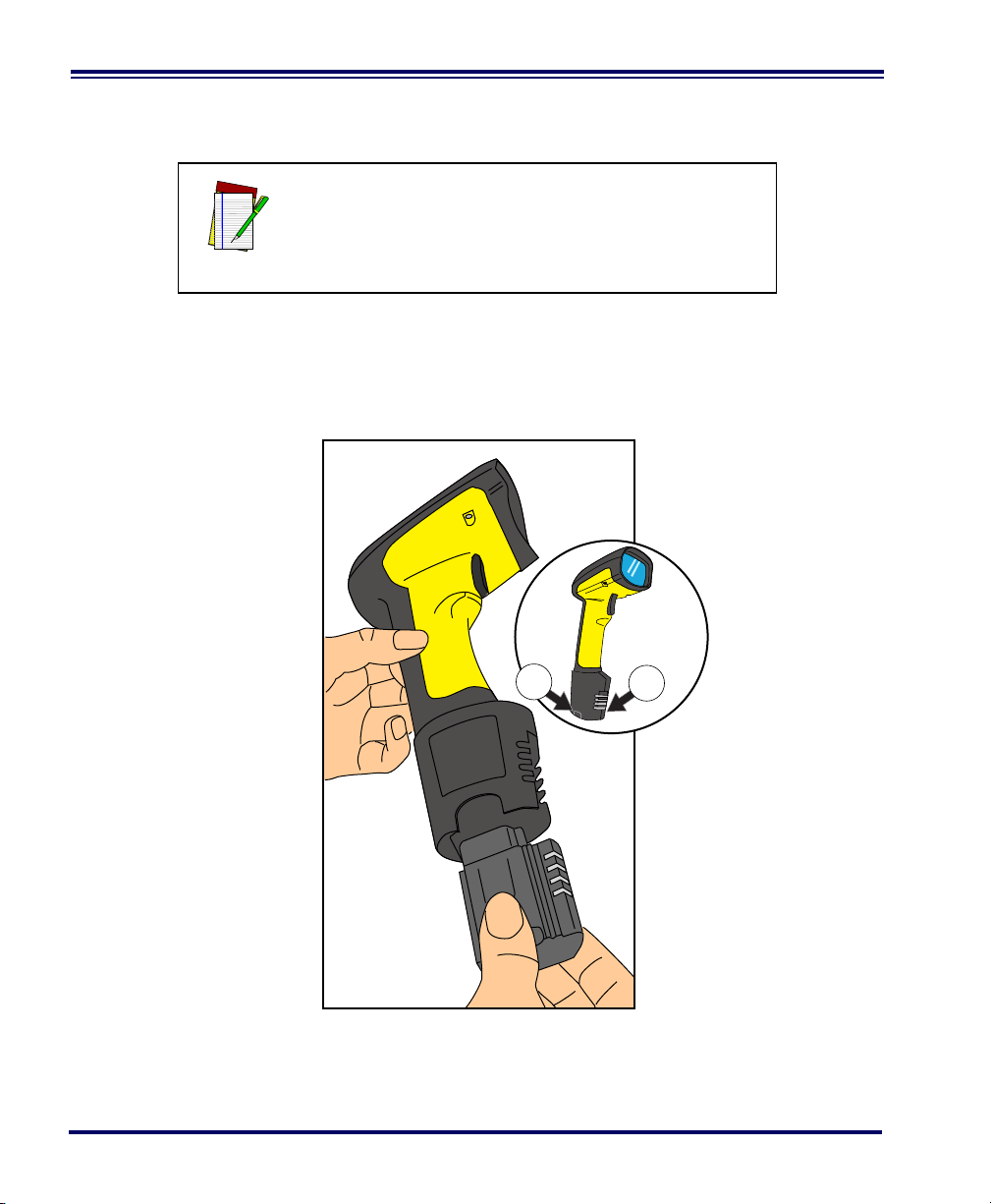
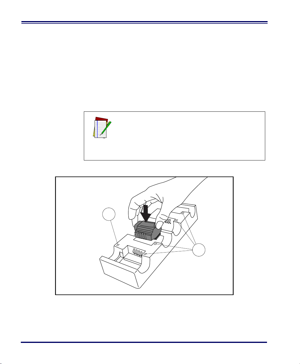
Installing the
1
1
Battery
NOTE
To assure maximum usage, batteries should always
be fully charged before their initial use. (See “Battery Charging and Maintenance” on page 10.)
Orient the battery as shown in Figure 1, then push it into the scanner
until it snaps in place. To remove the battery, push in on the release tabs
on both sides of the battery’s base and pull it straight out of the scanner.
Figure 1. Installing the Battery
1. Battery Release Tabs
4 PowerScan
®
RF Scanner
Page 13
Verifying
Scanner
Operation
Once a charged battery has been installed in the scanner, scan the sample bar codes in the back of this manual that correspond to the symbologies your scanner is programmed to read. If unsure how to do this,
see the section on How to Scan in this manual. The system may signal
with one or a combination of indicators depending upon how the scanner and Base Station are programmed to respond (see LED and Beeper
Indications for details). If your scanner fails to read a sample bar code of
a symbology it’s programmed to read, turn to the section titled, Tro u b l e -
shooting.
Power Supply Models require either a Listed class II or class III with a Limited Power
Source (LPS).
For the safety certification to be valid, class III input power sources
must be IEC/EN60950-1 (EN 60335-series, EN 60065 or relevant)
approved.
Input: 100 - 240 VAC Output: 9 - 10 VDC
Max. Current: 2.0 A Max. Power: 20 W
For 4-slot battery charger:
Input: 100 - 240 VAC Output: 12 VDC
Max. Current: 2.5 A Max. Power: 30 W
Connecting the
Base Station to
the Host
Terminal
It is important that the interface (I/F) cable be connected to the Base Station prior to applying power
to the system. This is because the interface type
(RS-232, IBM, Keyboard Wedge, etc.) is selected by
NOTE
the Base Station subject to the I/F cable it is connected to at the time of power-up.
1. Connect the I/F cable to the Base Station (see Figure 2A). The
I/F cable is inserted into the connector and the cable retainer
clip is rotated over the cable overmold until the retainer snaps
in place (see Figure 2B). To disconnect the cable, push in on the
retainer (away from the catch on the plastic wall) to release it
and enable it to swing upward, allowing the cable to be pulled
free (see Figure 2C).
User’s Guide 5
Page 14
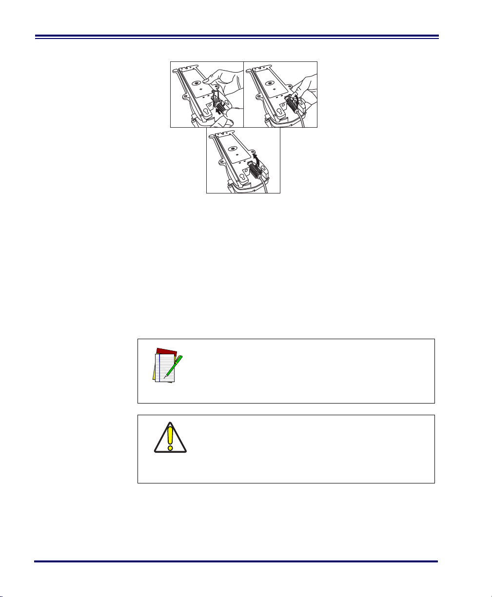
Figure 2. Connecting/Disconnecting the Interface (I/F) Cable
ab
c
2. Consult your Host Terminal manual to determine the required
communication parameters for the Host Terminal (e.g., baud
rate, parity, etc.) and, if necessary, modify the programmed
parameters to be compatible with those requirements. Scanner
and Base Station programming is performed using one of the
following:
- Configurator Express™ Programming Software
®
- PowerScan
Bar Code Scanner Programming Guide
NOTE
CAUTION
3. Connect the I/F cable to the proper port on the Host Terminal
(check your Host Terminal manual to determine hardware
requirements).
4. Connect the AC Adapter's power cord at the Base Station and
plug the AC/DC adapter in at the wall outlet (see Figure 3).
6 PowerScan
See References for more information about how to
obtain software and manuals for this product.
The Host Terminal manual should also be consulted
as to whether power must be turned off before connecting peripheral devices. Ensure that the correct
procedure is followed to avoid damage to equipment or interruption of system functions.
®
RF Scanner
Page 15

The Base Station’s POWER LED should be illuminated when
the unit is properly connected to power.
Figure 3. Connecting Power to the Base Station
5. Apply power to the Host Terminal.
6. Verify communication with the Host Terminal by aiming the
linked scanner at a sample bar code from the back pages of this
manual, and pulling the trigger (see How to Scan for tips about
scanning bar codes). Confirm that the scanner/Base Station
sent the data to the host terminal. If not, see the section, Tr ou -
bleshooting. Once all communications are verified, the system is
ready for use.
Linking the
Scanner to a
Base Station
To link a scanner to a Base Station, simply scan the Base Station ID bar
code located on the top of the desired Base Station. As the scanner
searches for the Base Station, a short beep is heard as it seeks for the
correct channel. When the Base Station responds to the request, the
scanner’s beeper will either sound a "Link Granted," or "Link Denied"
signal (see the section, LED and Beeper Indications for more information).
User’s Guide 7
Page 16
The existing Base Station system configuration can be automatically
downloaded to the scanner. This automatic download feature is configurable and can be disabled. See the Systems Manual for more information about this feature. If downloading occurs, a slight delay with link
verification announcement will occur.
Since a new/replacement scanner may have been
shipped with a custom configuration or may have
been modified with other special programming, it
may not be desirable to download a potentially
older configuration from an existing Base Station.
In this case, reference the Systems Manual, or the
CAUTION
Configurator Express™ On-Screen Programming
Software and consider uploading the scanner’s
newer configuration to the Base Station prior to
linking.
8 PowerScan
®
RF Scanner
Page 17
Verifying
Scanner-to-
Base Station
Communications
Point the linked scanner at a sample bar code from the back pages of
this manual, and pull the trigger (see How to Scan for tips on scanning
bar codes). Watch the TX/RX (transmit/receive) indicator LED on the
Base Station and/or scanner green LED while scanning the bar code.
The LEDs should flash momentarily as the two devices communicate.
If no communication is indicated, refer to the troubleshooting section
of the Systems Manual.
When the scanner is programmed to do so, communication can also be
indicated by a second "acknowledgement" tone
1
that is sounded after a
"good read" tone. If a transmission error beep (warble) is heard following a "good read" tone instead of the single acknowledgement tone,
communication between the devices may have failed
2
. Refer to the sections Using the PowerScan RF System, and Troubleshooting for possible
remedies, should this occur.
Mexico ONLY
Operation in Mexico must voluntarily be restricted
to channels 1,2,8 and 9. See RF Channel Selection
in the Systems Manual to set channels. The fre-
CAUTION
quency range on channels 3 through 7 have been
allocated by Mexico government standards.
1. See LED and Beeper Indications for more details about beeper signals.
2. Other reasons for a "warble" are that the Base Station may be configured differently than the scanner, or that the system’s interface doesn’t support the symbology (bar code type) you’re trying to
scan.
User’s Guide 9
Page 18
Using the PowerScan RF System
This section covers the following topics:
• Battery Charging and Maintenance
• How to Scan
• LED and Beeper Indications
Battery
Charging and
Maintenance
When the scanner is in use, a low battery condition
is indicated by a repeated two-flash signal from the
scanner’s green LED every time the trigger is pulled
before the laser is enabled. This indicator may have
NOTE
been disabled via custom programming. See LED
and Beeper Indications for more information.
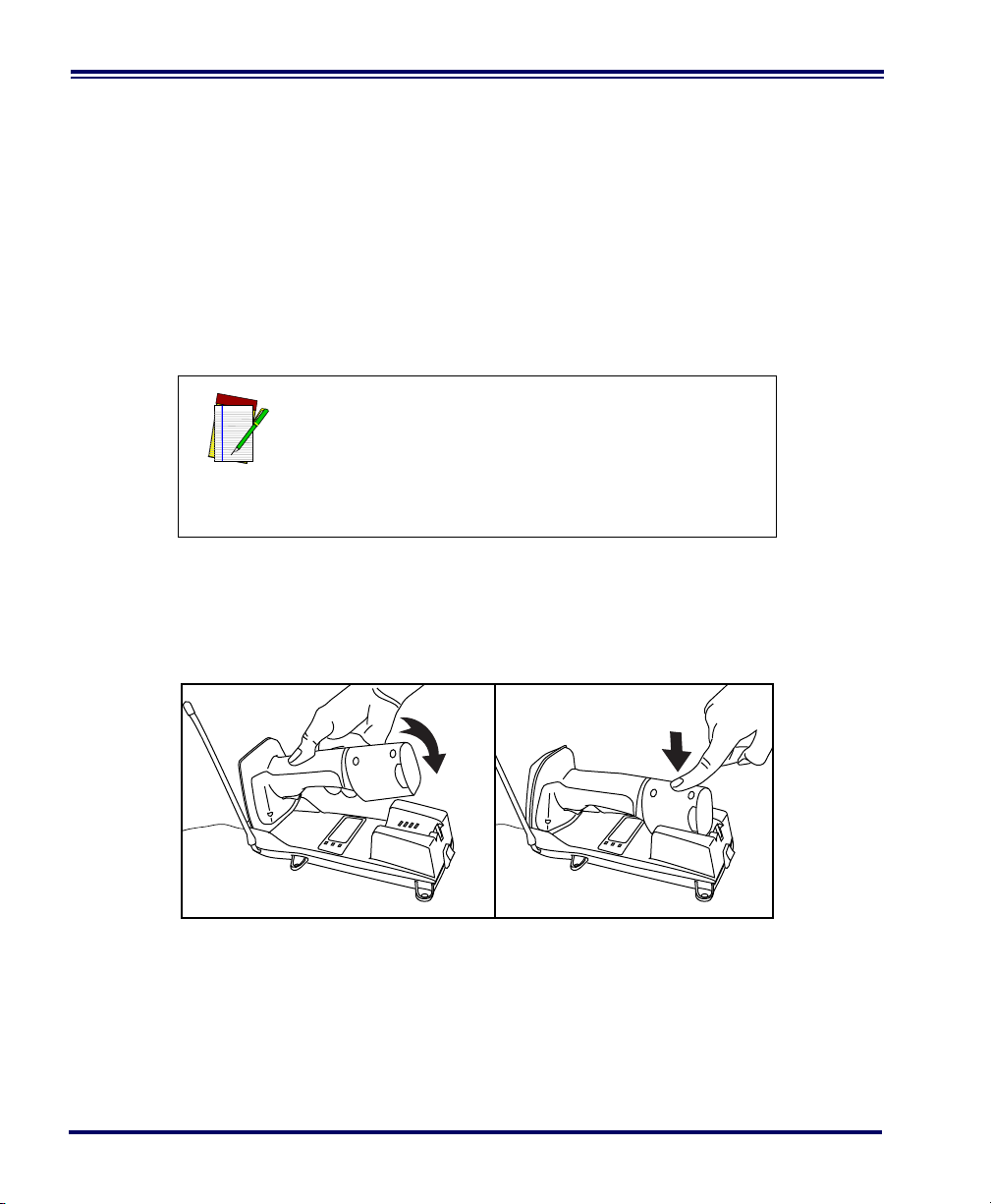
Seat the scanner in the Base Station as shown in Figure 4, ensuring that
the battery fully engages the station’s metal contacts. The CHARGE
LED on the Base Station should flash, indicating the battery is charging.
Figure 4. Charging the Battery
10 PowerScan
®
RF Scanner
Page 19
Rapid flashing indicates that charging is taking place. Rapid charging
occurs when the battery temperature is between 10°C (50°F) and 46°C
(115°F), and/or voltage of the battery is between 2.0 and 3.2V. Charge
time is less than 4.2 hours. Rapid charge ends with the battery at
approximately 90 to 95% capacity. The CHARGE LED remains on
steady when trickle charging or after the charge cycle is complete.
A scanner may be charged simultaneously while
other scanners are in use with the Base Station.
NOTE
Batteries will not charge if their temperature is
below 0°C (30°F). If a battery that is too cold is
inserted into the Base Station, the Charge LED will
NOTE
not illuminate.
Tips for
Extending
Battery Life
Nickel Metal Hydride (NiMH) batteries will better hold a charge if
allowed to discharge at least once a week. The chemical reactions that
correspond to charge and discharge in a rechargeable battery should
occur to obtain the maximum number of charge/discharge cycles in
the battery. If a battery is removed from the scanner and stored, it
should be fully charged when stored. Batteries will lose the ability to
hold a charge when stored for long periods of time (weeks, months, or
longer).
Batteries will typically have about 30% charge capacity when shipped.
To assure maximum usage, the battery should be fully charged before
use.
Store your battery in a cool dry place. Do not leave your battery
exposed to direct sunlight or temperatures below 0°C (30°F) and above
38°C (100°F).
Annual replacement of rechargeable battery packs
is recommended, to ensure maximum performance.
NOTE
User’s Guide 11
Page 20
Disposing of
1
2
Batteries
There presently are no US, North America or World disposal requirements for NiMH batteries, so when they won't hold a charge anymore,
the batteries can be disposed of, preferably through a recycling center.
Four Station
Charger
If you have a Four Station Charger, batteries are inserted for charging
as shown in Figure 5. A 90% rapid charge can be achieved in only two
hours when using this optional accessory, half the time than when a
Base Station is used for charging. The LEDs at each battery station
operate the same as the CHARGE LED on the Base Station, with rapid
flashing indicating that rapid charging is taking place and on steady
during trickle charging or when the rapid charge cycle is finished.
If you insert a battery into the Four Station Charger
and no LEDs illuminate, the battery may be too
cold. Batteries must be at 0°C or higher to charge.
Do not attempt to charge cold batteries, since plac-
NOTE
ing them in the charger will curtail the charging of
other batteries already present in the unit.
Figure 5. Using the Four Station Charger Accessory
1. Device Power LED 2. Station Charge LEDs
12 PowerScan
®
RF Scanner
Page 21
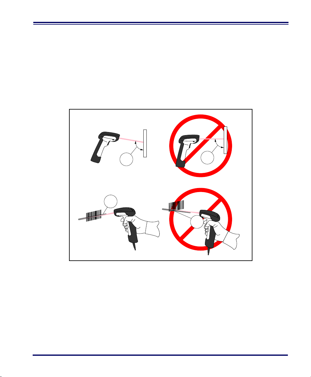
How to Scan
2
2
1
1
Figure 6 illustrates some tips to help get the best scanning results:
1. The scanner must be pointed at a slight angle to the bar code.
Do not hold the scanner perpendicular to the bar code.
2. The laser beam must cross the entire bar code. The scanner
cannot correctly read if the entire bar code is not scanned.
Figure 6. Scanning Tips
User’s Guide 13
Page 22
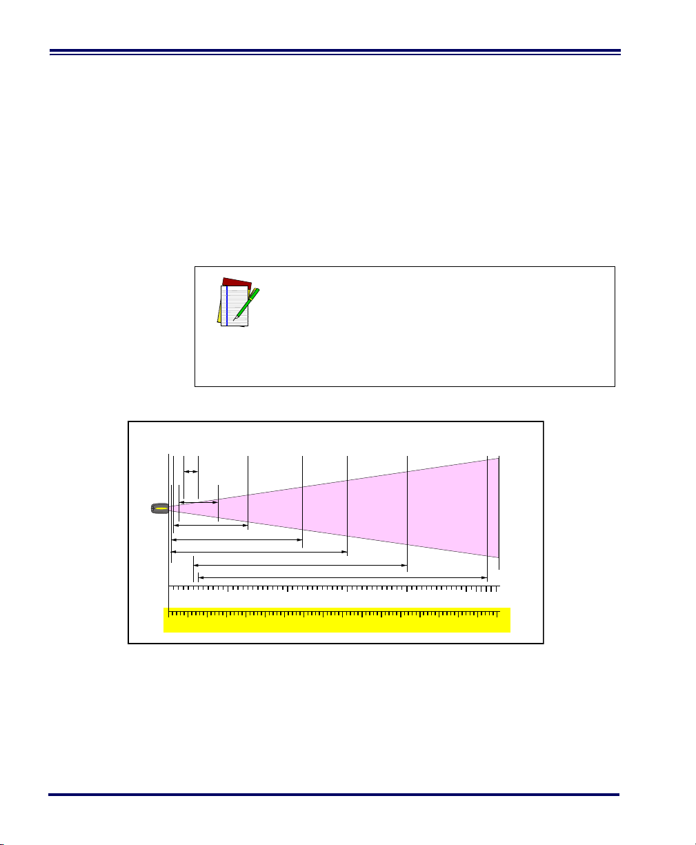
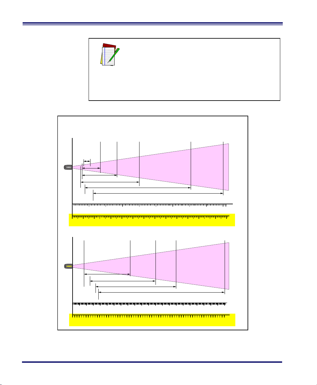
Depth of Field There are currently four different range models for the scanner.
Depth of Field
Paper Labels (SR decoded model, Code 39)
0
20 mil
15 mil
10 mil
5 mil
CENTIMETERS
FEET
FRONT OF SCANNER
10
12345
20 30 40 50 60 70 80 90 100 110 120 130 140 150 160 170
40 mil
7.5 mil
55 mil
Depending upon the model type of your scanner, you’ll need to hold
the unit at a given distance from the bar code to achieve optimum scanning results. The following diagrams provide depth of field information for each of the models when scanning grade A, Code 39 bar codes:
Standard Range (SR), High Density (HD), Long Range (LR) and Extra
Long Range (XLR).
Definition of
a "mil"
A "mil" is equal to 0.001 inches. In the context of the illustrations in this
section, a mil represents the minimum bar code element width. Thus a
5 mil bar code would have a minimum element width of 5 mils (or
0.005 inches).
Measurements are based on SR models set with the
standard 28° scan width (as opposed to the Half
Angle setting of 14°). Reference the Programming
Manual for more information about the Half Angle
NOTE
feature.
Specifications are subject to change without notice.
Figure 7. Depth of Field (SR)
14 PowerScan
®
RF Scanner
Page 23
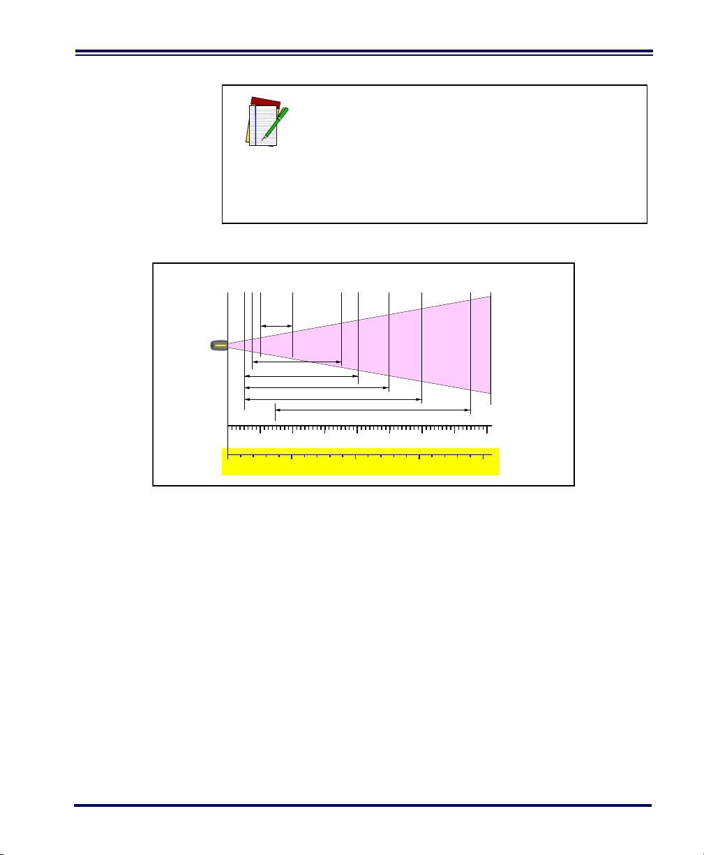
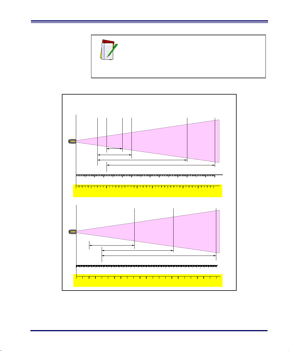
See the section titled, Definition of a "mil" for more
Depth of Field
Paper Labels (HD decoded model, Code 39)
7.5 mil
5 mil
4 mil
3 mil
INCHES
FRONT OF SCANNER
0
CENTIMETERS
5
12345678
10 15 20
10 mil
20 mil
information about reading this chart. Measurements
are based on HD models set with the standard 28°
scan width (as opposed to the Half Angle setting of
14°). Reference the Programming Manual for more
NOTE
information about the Half Angle feature.
Specifications are subject to change without notice.
Figure 8. Depth of Field (HD)
User’s Guide 15
Page 24
NOTE
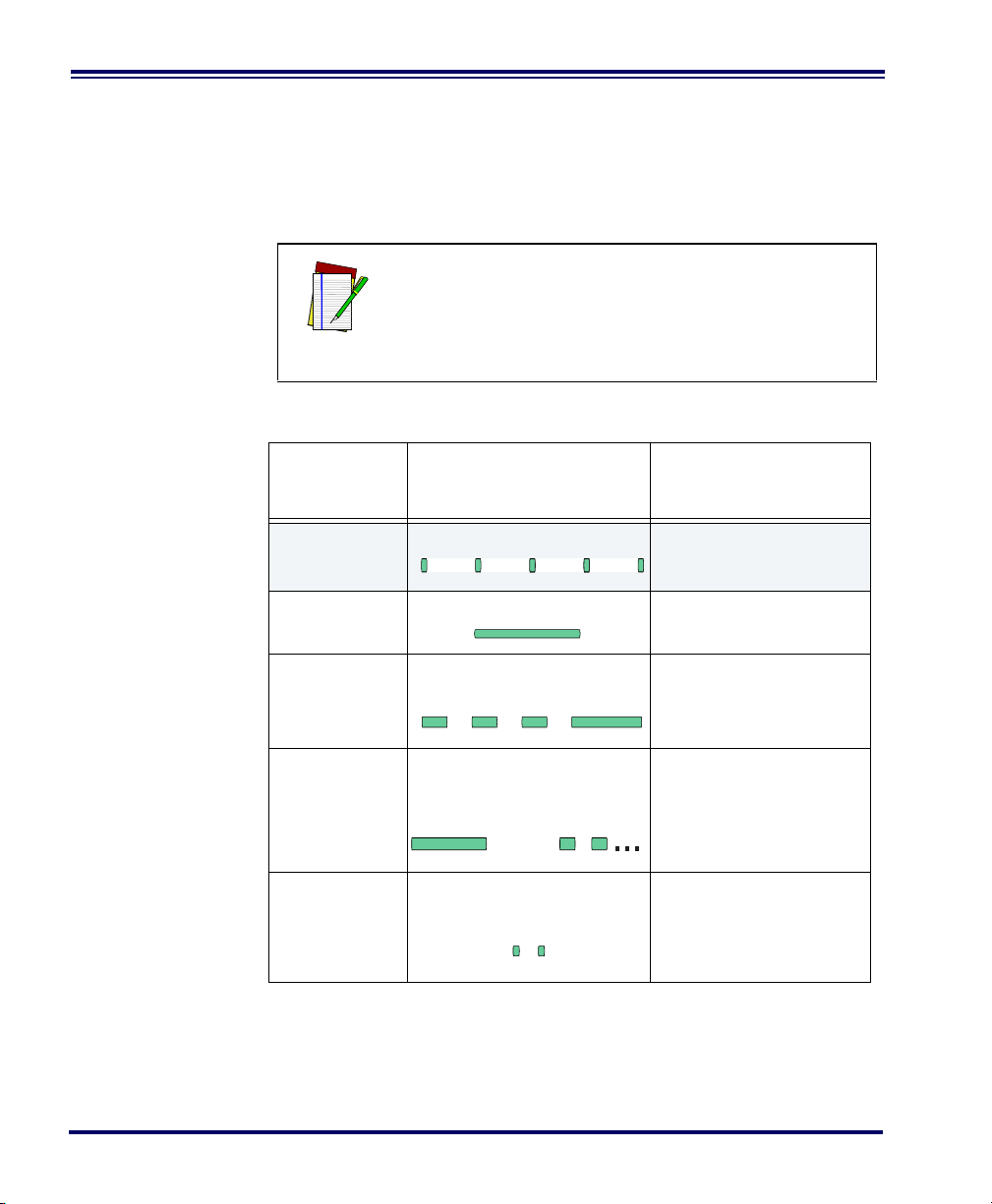
Depth of Field
Paper Labels (LR decoded model, Code 39)
0
40 mil
20 mil
15 mil
7.5 mil
CENTIMETERS
FEET
FRONT OF SCANNER
10
12345
20 30 40 50 60 70 80 90 100 110 120 130 140 150 160
6789
170 180 190 200 210 220 230 240 250 260 270 280
10 mil
55 mil
Reflective Labels (LR decoded model, Code 39)
70 mil
55 mil
40 mil
CENTIMETERS
FEET
FRONT OF SCANNER
6706506306105905705505305104904704504304103903703503303102902702502302101901701501301109070503010
102345678910 11 12 13 14 15 16 17 18 19 20 21 22
100 mil
Figure 9. Depth of Field (LR)
See the section titled, Definition of a "mil" for more
information about reading this chart. Measurements
are based on LR models set with the a 14° scan
width (as opposed to the alternate Full Angle setting of 28°). Reference the Programming Manual for
more information about the Half Angle feature.
Specifications are subject to change without notice.
16 PowerScan
®
RF Scanner
Page 25
NOTE
Depth of Field
Paper Labels (XLR decoded model, Code 39)
0
40 mil
20 mil
15 mil
CENTIMETERS
FEET
FRONT OF SCANNER
12345678910 11 12 13 14 15
45040035030025020015010050
55 mil
Reflective Labels (XLR decoded model, Code 39)
70 mil
40 mil
CENTIMETERS
FEET
FRONT OF SCANNER
1100105010009509008508007507006506005505004504003503002502001501005010
2345678910 11 12 13 14 15 16 17 18 19 20 21 22 23 24 25 2627 28 29 30 31 32 33 34 35 36
100 mil
Figure 10. Depth of Field (XLR)
See the section titled, Definition of a "mil" for more
information about reading this chart. Measurements
are based on XLR models set with a 10° scan angle
width.
Specifications are subject to change without notice.
User’s Guide 17
Page 26
LED and Beeper Indications
The Base Station LED indicators and the scanner’s LEDs and beeper
are used to announce system status and perform other useful signals.
The tables below list the default function of each of the various indicators.
NOTE
Some LED and beeper indications can be disabled
or modified via scanner programming. The tables
indicate the default behavior of the indicators, with
shaded rows representing features that are programmable.
Table 1. Scanner GREEN LED Functions
LED
INDICATION
Disable
Indication
Good Read
Indication
Program Mode
Indication
Field Replaceable Unit (FRU)
Indications
Low Battery
Indication
DURATION COMMENT
100ms on, 900 ms off
500 ms on
500 ms on, 500 ms off
Continuous flashing
Varies. Consists of a long flash
followed by multiple short
flashes.
Two flashes at 100 ms on, 350
ms off.
Indicates the scanner has
been disabled.
Indicates a bar code has
been read and decoded.
Indicates the scanner is in
Programming Mode.
Enables service technicians to identify Field
Replaceable Unit (FRU)
errors.
Occurs at trigger pull before
the laser is enabled. Indicates the battery is in need
of recharging.
18 PowerScan
®
RF Scanner
Page 27
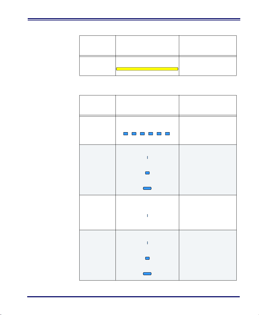
Table 2. Scanner YELLOW LED Functions
LED
INDICATION
Laser on indication
SPEAKER
INDICATION
Scanner Not
Currently
Linked
Good Read
Beep
DURATION COMMENT
On Steady
The yellow LED illuminates
whenever the laser is on.
Table 3. Scanner BEEPER Functions
DURATION COMMENT
Six beeps consisting of 20 ms
on, 20 ms off
100 ms on (short)
250 ms on (medium)
500 ms on (long)
Indicates a bar code was
read before the scanner
was linked to a Base Station.
Three programmable functions are available. This
indicates a bar code has
been read and decoded.
A very short beep ("bip") is
Partial Read
Bip
Base Station
Acknowledgement Beep
20 ms on
100 ms on (short)
250 ms on (medium)
500 ms on (long)
sounded when one bar
code of a two-bar code pair
has been successfully
decoded.
Indicates a successful bar
code transmission to the
host (configurable), a successful change of channel,
or a successful transmission of a new configuration
to the host.
User’s Guide 19
Page 28

SPEAKER
INDICATION
Transmission
Error Beep
DURATION COMMENT
High, then low, then high, then
low.
Indicates unsuccessful
transmission to the host.
Link Beep
Unlink Beep
Field Replaceable Unit (FRU)
Indications
LED
INDICATION
TX/RX (Transmit/Receive)
Low, then medium, then high.
High, then medium, then low.
Varies. Consists of a long tone
followed by multiple short
tones.
Indicates a scanner has
been successfully linked to
a base station.
Indicates a scanner has
been successfully unlinked
from a base station.
Enables service technicians to identify Field
Replaceable Unit (FRU)
errors.
Table 4. Base Station LED Functions
DURATION COMMENT
Lit for variable time
Continuous rapid
flashing at power-up
Varies. Consists of a long flash
followed by multiple short
flashes.
a
Indicates communications
activity to or from the Base
Station.
Indicates a broken radio.
Enables service technicians to identify Field
Replaceable Unit (FRU)
errors.
20 PowerScan
®
RF Scanner
Page 29

LED
INDICATION
Charge
(Battery)
DURATION COMMENT
Continuous flashing
Lit Constantly
Not Lit
When a scanner is nested
in the station, this indicates
its battery is being quick
charged.
When a scanner is nested
in the station, this indicates
its battery is at or near full
charge.
A scanner is not present or
incorrectly inserted into the
station. It can also mean
the battery is below 0°C
(too cold for charge)
Active
Symbologies
Power
a. The LED remains on while the unit is actively processing code which
requires a TX/RX to occur. The duration of the LED is dependent upon
the length of the message.
The active (enabled) bar code symbologies in the standard factory
defaults are:
Lit Constantly
Indicates that power is on.
• Code 39 (C39)
• Code 128 (C128)
• Interleaved 2 of 5 (I 2 of 5)
Your scanner should be pre-programmed with these standard factory
default settings, unless...
...it was shipped to you programmed with unique, customer con-
figuration settings.
...you or another user have made changes to scanner program-
ming.
User’s Guide 21
Page 30
Enhanced
CAUTION—LASER RADIATION WHEN OPEN. AVOID EXPOSURE TO BEAM.
COVERED
BY ONE OR MORE OF THE
FOLLOWING PATENTS:
4,387,297 • 4,409,470 • 4,460,120
4,593,186 • 4,652,750 • 4,673,805
4,736,095 • 4,816,660 • 4,845,350
4,861,972 • 4,866,257 • 4,879,456
5,179,270 • 5,180,904 • 5,237,161
5,247,161 • 5,247,162 • 5,258,604
5,260,554 • 5,298,728 • 5,311,000
5,330,370 • 5,468,949 • 5,475,206
5,481,098
Other patents pending
RF
1
2
3
4
6
5
Scanning for
Hard-to-Read
Bar Codes
Decoded scanners can be programmed to decode extremely poor quality bar codes by activating advanced Quadralogic II™ Decoding. To
select this feature, see the Programming Guide.
Scanner programming can also be performed using your PC and the
Configurator Express™ On-Screen Programming Kit.
Information about manuals, kits and programming
software for this product are available at our website. See the back cover for our web address.
NOTE
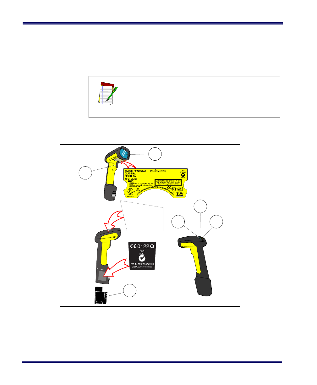
Figure 11. Scanner Labeling and Nomenclature
1. Trigger 4. Tether Hook
2. Scan Window 5. Yellow LED
3. Green LED 6. Battery
22 PowerScan
®
RF Scanner
Page 31

Laser Cautions
Figure 11 above shows label placement ONLY. For
actual regulatory, patent and other applicable information, view the labels on the product itself, or call
NOTE
your nearest sales or service representative.
The PowerScan RF bar code scanner is certified in the U.S. to conform
to the requirements of DHHS/CDRH 21CFR Subchapter J for Class II laser
products (SR and LR) and Class IIIa (XLR). Class II and IIIa products are
not considered to be hazardous. The scanner contains a Visible Laser
Diode (VLD) at a wavelength of 650-670 nanometers and is designed so
that there can be no human access to harmful levels of laser light during normal operation, user maintenance, or during prescribed service
operations.
In the unlikely event that a bright laser spot is experienced rather than a scan line, do not stare into the
beam or attempt to repair the unit. Discontinue
operation and return the unit to your dealer. Note
CAUTION
that when using Marker Beam Mode, a single aiming dot is projected momentarily preceding a scan
line and is not considered a malfunction.
Do not open or otherwise service any components
in the optics cavity. Opening or servicing any part
of the optics cavity by unauthorized personnel may
CAUTION
NOTE
violate laser safety regulations. The optics system
is a factory only repair item.
The PowerScan
in conjunction with the Datalogic Base Station,
Model: PowerScan RF Base Station.
®
RF scanner is required to be used
User’s Guide 23
Page 32

Radio Frequency Interference
This device complies with Part 15 of the FCC Rules. Operation is subject to the following two conditions:
1. This device may not cause harmful interference, and
2. This device must accept any interference received, including
interference that may cause undesired operation.
This Class A digital apparatus complies with Canadian ICES-003.
Cet appareil numérique de la classe A est conforme à la norme NMB-
003 du Canada.
This equipment has been tested and found to comply with the limits
for a Class B digital device, pursuant to Part 15 of the FCC Rules. These
limits are designed to provide reasonable protection against harmful
interference in a residential installation. This equipment generates,
uses and can radiate radio frequency energy and, if not installed and
used in accordance with these instructions, may cause harmful interference to radio communications. However, there is no guarantee that
interference will not occur in a particular installation. If this equipment
does cause harmful interference to radio or television reception, which
can be dertermined by turning the equipment off and on, the user is
encouraged to try to correct the interference by one or more of the following measures:
• Reorient or relocate the receiving antenna.
• Increase the separation between the equipment and receiver.
• Connect the equipment into an outlet on a circuit different
from that to which the receiver is connected.
• Consult the dealer or an experienced radio/TV technician for
help.
24 PowerScan
®
RF Scanner
Page 33

Maintenance
The scan window will require occasional cleaning to remove smudges,
dust and other debris. To ensure optimal performance, clean the Scan
Window using a soft cloth or lens tissue dampened with isopropyl
alcohol (or equivalent). See Figure 12. The scanner body can also be
cleaned using this method.
Figure 12. Cleaning the Scan Window
User’s Guide 25
Page 34

Troubleshooting
Troubleshoot your RF scanning system by performing the following
checks:
For the RF system, ensure that...
• the battery is charged. See “Battery Charging and Mainte-
nance” on page 10.
• the battery is properly installed. See “Installing the Battery” on
page 4.
• the scanner is linked to the desired Base Station. See “Linking
the Scanner to a Base Station” on page 7.
• the scanner is within reasonable operating range of the Base
Station, with no major obstructions between the radio units
such as thick walls or heavy machinery. (At the time of this
writing, maximum line-of-sight range is specified at 150 feet.)
• there is no local signal interference with other radio-operated
equipment. Consult the Systems Manual concerning selection
of alternate channels.
• the Base Station is powered-on. You can verify the Base Sta-
tion’s AC Adapter by using a known-good AC Adapter.
• the Base Station interface cable is securely attached to the host.
Consult your technical support manager or refer to your host
system manual to identify the proper cable connection for the
scanner. If necessary, verify interface cable function by using a
known-good interface cable.
If the problem is specific to scanning, verify that...
• the bar codes you are trying to scan are of satisfactory quality.
Bar code label verifiers are available from your dealer if you
need precise reporting of label details. Bar codes that are damaged (wrinkled, smudged, or torn) may cause the scanner to
read poorly or not at all. If bar code quality seems to be the
problem, check to see if the scanner will read a sample bar
code from the following pages.
• the programmable setting for advanced Quadralogic II™
decoding is set optimally for your system. (See See “Enhanced
Scanning for Hard-to-Read Bar Codes” on page 22.)
26 PowerScan
®
RF Scanner
Page 35

Sample Bar Codes
Code 128 . Tes t
CODE 3 9 . TES T
0123456789
1 2 3 4 5 6 7 8 9 0
A$99 . 95A
Use these test bar codes to check the scanner’s ability to read the various symbologies represented.
Code 128
Code 39
Interleaved 2 of 5
Standard 2 of 5
User’s Guide 27
Codabar
Code 93
Code 9 3.Test
Page 36

MSI/Plessey
14476925
4
0
00112 23344
0
4
9
0
6
0
9
9
2
0
1
1
1
8
7
6
9
0
0
0
0
0
8
0
2
9
5
1
0
4
1
8
0
9
9
8
8
7
5
0
0
0
2
1
0
1
2
6
1 101234 56789 1
UPC-A
UPC-A with 2 digit Add-on
UPC-A with 5 digit Add-on
28 PowerScan
UPC-E
EAN-8
EAN-13
®
RF Scanner
Page 37

DEUTSCHES INHALTSVERZEICHNIS
Auspacken und Überprüfen Ihres Scanners ................................................................31
Referenzen ..................................................................................................................31
Anweisungen für den Schnellstart ...............................................................................31
Einlegen der Batterie ............................................................................................32
Überprüfen des Scannerbetriebes ........................................................................33
Netzteil ..................................................................................................................33
Anschließen der Basisstation an das Hauptterminal ............................................33
Verbinden des Scanners mit der Basisstation ......................................................35
Prüfen der Verbindung Scanner-an-Basisstation ..................................................37
Anwenden des PowerScan RF-Systems .....................................................................38
Batterieaufladung und Wartung ............................................................................38
Tipps zur Verlängerung der Batteriehaltbarkeit ....................................................39
Entsorgung der Batterien ......................................................................................39
Vier-Stationen-Ladegerät ......................................................................................40
Wie wird gescannt .......................................................................................................41
Feldtiefe ................................................................................................................42
LED- und Signal-Anzeigen ..........................................................................................46
Aktive Symboliken .................................................................................................50
Erweitertes Scannen für schlecht lesbare Barcodes ............................................50
Warnhinweise für Laseranwendung ............................................................................52
Hochfrequente Störungen ...........................................................................................53
Wartung .......................................................................................................................54
Fehlersuche .................................................................................................................55
Muster-Barcodes .........................................................................................................57
Benutzerhandbuch 29
Page 38

Datalogic Scanning Inc.
959 Terry Street
Eugene, Oregon 97402
Tel.: (541) 683-5700
Fax: (541) 345-7140
Datalogic, das Datalogic-Logo, Quadralogic II und PowerScan sind
eingetragene Warenzeichen der Datalogic Scanning, Inc. Alle anderen
hier genannten Waren-zeichen und Handelsnamen sind Eigentum der
jeweiligen Besitzer.
Alle Rechte vorbehalten. Ohne die vorherige schriftliche Zustimmung
der Datalogic Scanning, Inc. dürfen keine Inhaltsabschnitte dieser
Dokumentation oder der hier beschriebenen Verfahren in irgendeiner
Form oder mit irgendwelchen Mitteln vervielfältigt oder übertragen werden. Den Eigentümern von Produkten der Datalogic Scanning, Inc.
wird hiermit eine nicht aus-schließliche, widerrufliche Lizenz zur
Vervielfältigung und Übertragung dieser Dokumentation gewährt, die
nur für die internen Geschäftszwecke des Käufers gilt. Der Käufer ist
nicht berechtigt, die in dieser Dokumentation enthaltenen Hinweise des
Eigentümers, einschließlich der Copyright-Hinweise, zu entfernen oder
zu ändern, und er gewährleistet, dass alle Hinweise auf jeglichen
Vervielfältigungen der Dokumente erscheinen.
Wenn zukünftig Überarbeitungen dieses Handbuches herausgegeben
werden, können Sie die gedruckten Versionen über die Datalogic Kundenverwaltung erhalten. Die elektronischen Versionen können
entweder von der Datalogic-Webseite (www.scanning.datalogic.com)
heruntergeladen werden oder Ihnen auf einem entsprechenden
Medium geschickt werden. Wenn Sie unsere Webseite besuchen und
zu dieser Webseite oder anderen Datalogic-Veröffentlichungen Ihren
Kommentar oder Vorschläge abgeben möchten, dann ist dies über die
Seite "Contact Datalogic" möglich.
Haftungsausschluss
Es wurden angemessene Maßnahmen ergriffen, damit die in
diesem Handbuch enthaltenen Informationen vollständig und
korrekt sind. Datalogic behält sich jedoch das Recht vor, Spezifikationen ohne vorherige Mitteilung und zu jeder Zeit zu
ändern.
30 PowerScan
®
RF Handstrichcodeleser
Page 39

Auspacken und Überprüfen Ihres Scanners
Nachdem Sie Ihren neuen Scanner ausgepackt haben, überprüfen Sie
den Inhalt des Lieferkartons, ob auch alle von Ihnen bestellten Teile
geliefert wurden:
• PowerScan
®
RF Handscanner
• Batterie/n
• Benutzerhandbuch (dieses Handbuch)
• zusätzliches Zubehör, das Sie bestellt haben. (Der Scanner
kann mit oder ohne Zubehör-Kit bestellt werden)
Wenn Ihr Paket falsche Teile enthält oder wenn Teile fehlen, wenden
Sie sich bitte an Ihre Verkaufsstelle. Wenn beschädigte Teile enthalten
sind, dann legen Sie umgehend Ihre Forderung dem Frachtunternehmen vor. Bewahren Sie das Verpackungsmaterial auf, falls Sie den
Scanner zu einem späteren Zeitpunkt versenden möchten.
Referenzen
Weitere Informationen zu diesem Produkt, zu darauf bezogenen
Veröffentlichungen, Software und Zubehör erhalten Sie auf unserer
Webseite, die auf der Rückseite dieses Handbuches angegeben ist.
Anweisungen für den Schnellstart
Die nachfolgenden Grundschritte müssen ausgeführt werden, um den
RF-Scanner in Betrieb zu nehmen. Jeder dieser Schritte ist ausführlich
in diesem Handbuch beschrieben.
• Einlegen der Batterie
• Überprüfen des Scannerbetriebes
• Anschließen der Basisstation an das Hauptterminal
• Verbinden des Scanners mit der Basisstation
• Prüfen der Verbindung Scanner-an-Basisstation
Benutzerhandbuch 31
Page 40

Einlegen der
1
1
Batterie
Hinweis
Für eine maximale Lebensdauer sollten die Batterien vor der ersten Anwendung immer vollständig
aufgeladen sein. (Siehe “Batterieaufladung und
Wartung” auf Seite 38).
Richten Sie die Batterie wie in Abbildung 1 gezeigt aus und drücken
Sie die Batterie dann so weit in den Scanner, bis sie einrastet. Die Batterie wird herausgenommen, indem Sie auf die Lösetasten an beiden
Seiten des Batterieteils drücken und die Batterie gerade aus dem Scanner herausziehen.
Abbildung 1: Einlegen der Batterie
1. Batterie-Lösetasten
32 PowerScan
®
RF Handstrichcodeleser
Page 41

Überprüfen des
Scannerbetriebes
Netzteil Die Modelle erfordern eine Stromquelle der Klasse II oder III mit einer
Anschließen der
Basisstation an
das Hauptterminal
Sobald die aufgeladene Batterie in den Scanner eingelegt wurde, scannen Sie jene Muster-Barcodes auf den letzten Seiten dieses Handbuches, die der Symbolik entsprechen, für die Ihr Scanner
programmiert ist. Wenn Sie sich über die Vorgehensweise unsicher
sind, lesen Sie den Abschnitt dieses Handbuches "Wie wird gescannt".
Das System kann ein Signal an einer oder an einer Kombination von
Anzeigen abgeben, dies ist abhängig von der Antwort-Programmierung des Scanners und der Basisstation (siehe "LED- und SignalAnzeigen" für weitere Erklärungen). Wenn Ihr Scanner nicht einen
Muster-Barcode der Symbolik lesen kann, für die er programmiert ist,
lesen Sie den Abschnitt "Fehlersuche".
Leistungsbegrenzung (LPS).
Für eine gültige Sicherheitszertifizierung müssen Klasse III Stromquellen am Eingang nach den Bestimmungen IEC/EN60950-1 (EN
60335-Serien, EN 60065 oder entsprechenden) zugelassen sein.
Eingang: 100 - 240 VAC Ausgang: 9 - 10 VDC
Max. Strom: 2.0 A Max. Leistung: 20 W
Für 4-fach Batterieladegerät
Eingang: 100 - 240 VAC Ausgang: 12 VDC
Max. Strom: 2.5 A Max. Leistung: 30 W
Vor dem Anschließen an das Stromnetz muss das Schnittstellenkabel (I/F) an die Basisstation angeschlossen werden. Das ist deshalb
wichtig, weil der Schnittstellentyp (RS-232, IBM, Keyboard Wedge,
Hinweis
usw.) von der Basisstation über das I/F-Kabel gewählt wird, an dem
sie zum Zeitpunkt der Stromzufuhr angeschlossen ist.
1. Schließen Sie das I/F-Kabel an die Basisstation an (siehe
Abbildung 2A). Das I/F-Kabel wird in den Anschlussstecker
eingeführt und die Kabelrückhalteklemme wird so weit über
die Kabel-Überform gedreht, bis der Rückhalter einrastet
(siehe Abbildung 2B). Um das Kabel zu lösen, drücken Sie den
Rückhalter zum Lösen ein (von der Sperre an der Kunststoffwand weg), damit er nach oben schwingen kann und das
Kabel frei liegt (Abbildung 2C).
Benutzerhandbuch 33
Page 42

Abbildung 2 Anschließen/Trennen des Schnittstellen-(I/F)Kabels
ab
c
2. Lesen Sie im Hauptterminal-Handbuch die erforderlichen
Kommunikationsparameter für das Hauptterminal nach (z.B.
Baud-Rate, Parität, usw.) und ändern Sie falls erforderlich die
programmierten Parameter, damit diese mit den Anforderungen übereinstimmen. Die Programmierung des Scanners und
der Basisstation wird mit einem der folgenden Mittel ausgeführt:
- Configurator Express™ Programming Software
®
- PowerScan
Bar Code Scanner Programming Guide
Hinweis
Achtung
3. Schließen Sie das I/F-Kabel an den richtigen Anschlussstecker
des Hauptterminals an (lesen Sie im Hauptterminal-Handbuch
den Abschnitt zu Hardwareanforderungen).
34 PowerScan
Siehe "Referenzen" für weitere Einzelheiten dazu,
wie Sie die Software und Handbücher für dieses
Produkt erhalten.
Im Hauptterminal-Handbuch muss nachgeschlagen
werden, ob der Netzstrom vor dem Anschluss der
Peripheriegeräte abgeschaltet sein muss. Vergewissern Sie sich, dass das richtige Verfahren eingehalten wird, damit Schäden an der Ausrüstung oder
eine Unterbrechung der Systemfunktionen vermieden werden.
®
RF Handstrichcodeleser
Page 43

4. Schließen Sie das Stromkabel des AC-Adapters an die Basissta-
tion an und stecken Sie den AC/DC-Adapter in die Wandsteckdose (siehe Abbildung 3). Die Strom-LED der Basisstation
leuchtet, wenn die Einheit korrekt an das Stromnetz angeschlossen ist.
Abbildung 3: Die Basisstation mit dem Stromnetz verbinden
5. Schalten Sie den Strom für das Hauptterminal an.
6. Prüfen Sie die Kommunikation mit dem Hauptterminal, in
dem Sie den verbundenen Scanner auf einen Muster-Barcode
der letzten Seiten dieses Handbuches halten und den Auslöser
ziehen (für Tipps über das Scannen von Barcodes siehe "Wie
wird gescannt"). Prüfen Sie, ob der Scanner/die Basisstation
die Daten zum Hauptterminal sendet. Wenn nicht, siehe
Abschnitt "Fehlersuche". Sobald alle Kommunikationen überprüft sind, ist das System betriebsbereit.
Verbinden des
Scanners mit der
Basisstation
Der Scanner wird mit der Basisstation verbunden, in dem einfach der
ID-Barcode für die Basisstation gescannt wird, den Sie oben auf der
entsprechenden Basisstation finden. Während der Scanner die Basisstation sucht, hören Sie einen kurzen Signal, der die Kanalsuche anzeigt.
Wenn die Basisstation auf die Suche reagiert, dann ändert sich der
Signalton des Scanners zu einem Signal "Verbindung gewährt" oder
"Verbindung verweigert" (für weitere Informationen siehe Abschnitt
"LED- und Signal-Anzeigen").
Benutzerhandbuch 35
Page 44

Die bestehende Systemkonfiguration der Basisstation kann automatisch auf den Scanner übertragen werden. Dieses Merkmal der automatischen Übertragung kann konfiguriert und abgestellt werden. Für
weitere Informationen zu diesem Merkmal siehe Systemhandbuch. Bei
einer Übertragung tritt eine leichte Verzögerung der Anzeige der
Verbindungsüberprüfung auf.
Da ein neuer/Austausch-Scanner mit einer Kundenkonfiguration geliefert oder mittels einer anderen
speziellen Programmierung geändert sein kann, ist
das Downloaden einer möglicherweise älteren Konfiguration von einer bestehenden Basisstation nicht
empfehlenswert. In diesem Fall ist es ratsam, über
Achtung
das Systemhandbuch oder die Configurator
Express™ On-Screen Programming Software die
neuere Konfiguration des Scanners vor der Verbindung auf die Basisstation zu übertragen.
36 PowerScan
®
RF Handstrichcodeleser
Page 45

Prüfen der
Verbindung
Scanner-an-
Basisstation
Halten Sie den verbundenen Scanner auf einen Muster-Barcode der
letzten Seiten dieses Handbuches und ziehen Sie den Auslöser (für
Tipps zum Scannen von Barcodes siehe "Wie wird gescannt"). Während
Sie den Barcode scannen, beobachten Sie die LED-Anzeige TX/RX
(übertragen/empfangen) auf der Basisstation und/oder die grüne LED
am Scanner. Die LEDs sollten vorübergehend aufblinken, wenn die
beiden Geräte miteinander in Verbindung sind. Wird keine Kommunikation angezeigt, dann lesen Sie den Abschnitt "Fehlersuche" im Systemhandbuch.
Sofern der Scanner darauf programmiert ist, wird die Kommunikation
auch durch einen zweiten "Bestätigungston" angezeigt, der nach dem
"Übertragung-gut"-Ton ertönt
1
. Wenn der Signal für eine fehlerhafte
Übertragung (Wobbelton) nach einem "Übertragung-gut"-Ton zu hören
ist anstelle eines einzigen Bestätigungstons, dann ist die Kommunikation zwischen den Geräten möglicherweise nicht zustande gekom-
2
men
. Wenn dieser Fall auftritt, versuchen Sie mit Hilfe der Abschnitte
"Anwenden des PowerScan RF-Systems" und "Fehlersuche" das Problem zu beheben.
1. Für weitere Einzelheiten über Signal siehe "LED- und Signal-Anzeigen"
2. Andere Gründe für einen "Wobbelton" sind, dass die Basisstation möglicherweise anders als der
Scanner konfiguriert ist oder dass die Systemschnittstelle nicht die Symbolik unterstützt (Barcodetyp), die Sie versuchen einzuscannen.
Benutzerhandbuch 37
Page 46

Anwenden des PowerScan RF-Systems
Dieser Abschnitt behandelt die folgenden Punkte:
• Batterieaufladung und Wartung
• Wie wird gescannt
• LED- und Signal-Anzeigen
Batterieaufladung
und Wartung
Wenn der Scanner in Betrieb ist, wird über ein wiederholtes zweimaliges Blinksignal der grünen LED
des Scanners jedes Mal ein niedriger Batteriezustand angezeigt, wenn der Auslöser vor der
Aktivierung des Lasers gezogen wird. Diese
Hinweis
Anzeige kann über die Kundenprogrammierung
abgestellt worden sein. Für weitere Informationen
siehe "LED- und Signal-Anzeigen".
Legen Sie den Scanner wie in Abbildung 4 gezeigt in die Basisstation
und vergewissern Sie sich, dass die Batterie vollständig mit den Metallkontakten der Station eingerastet ist. Die Aufladungs-LED an der
Basisstation sollte jetzt blinken und damit anzeigen, dass die Batterie
aufgeladen wird.
Abbildung 4: Aufladung der Batterie
38 PowerScan
®
RF Handstrichcodeleser
Page 47

Ein schnelles Blinken zeigt an, dass das Aufladen stattfindet. Ein
schnelles Aufladen erfolgt, wenn die Batterietemperatur zwischen
10°C (50°F) und 46°C (115°F) liegt, und/oder die Batteriespannung
zwischen 2,0 und 3,2 V liegt. Die Ladezeit beträgt weniger als 4,2
Stunden. Die schnelle Aufladung wird bei einer 90 bis 95%-igen Batterieleistung abgeschlossen. Die Aufladungs-LED leuchtet kontinuierlich, wenn die Batterie langsam aufgeladen wird oder wenn der
Ladezyklus abgeschlossen ist.
Ein Scanner kann gleichzeitig geladen werden,
während andere Scanner mit der Basisstation in
Hinweis
Hinweis
Betrieb sind.
Batterien laden sich unterhalb einer Temperatur von
0°C (30°F) nicht auf. Wenn eine zu kalte Batterie in
eine Basisstation gelegt wird, dann leuchtet die
Lade-LED nicht auf.
Tipps zur
Verlängerung der
Batteriehaltbarkeit
Entsorgung der
Batterien
Nickel-Metall-Hydrid-(NiMH)Batterien halten länger, wenn sie wenigstens einmal pro Woche entladen werden. Die chemischen Reaktionen,
die bei einer wiederaufladbaren Batterie einem Auf- und Entladen
entsprechen, sollten auftreten, um die maximale Anzahl der Auf-/
Entladungszyklen der Batterie zu erzielen. Wenn eine Batterie aus dem
Scanner genommen und gelagert wird, dann sollte sie für die Lagerung
vollständig aufgeladen sein. Batterien verlieren durch lange
Lagerzeiten (Wochen, Monate oder länger) ihre Fähigkeit, einen Ladezustand beizubehalten.
Bei der Lieferung sind die Batterien in der Regel zu 30% geladen. Um
eine maximale Nutzung zu garantieren, sollte die Batterie vor der
Anwendung vollständig aufgeladen sein.
Lagern Sie die Batterie an einem kühlen und trockenen Ort. Setzen Sie
die Batterie niemals der direkten Sonnenbestrahlung oder Temperaturen unterhalb von 0°C (30°F) und über 38°C (100°F) aus.
Derzeit bestehen keine Entsorgungsanforderungen für NiMH-Batterien in den Vereinigten Staaten, Nordamerika oder weltweit. Wenn die
Batterien also nicht mehr die Ladung halten, dann können sie vorzugsweise über eine Recyclingzentrale entsorgt werden.
Benutzerhandbuch 39
Page 48

Vier-Stationen-
1
2
Ladegerät
Abbildung 5: Anwenden des Zubehörs Vier-Stationen-Ladegerät
Wenn Sie über ein Vier-Stationen-Ladegerät verfügen, dann werden
die Batterien zur Aufladung wie in Abbildung 5 gezeigt eingelegt. Eine
90%-ige Aufladung wird in nur zwei Stunden erzielt, wenn dieses
zusätzliche Zubehör verwendet wird - dass entspricht der Hälfte der
Zeit, die für eine Aufladung über die Basisstation erforderlich ist. Die
LEDs an jeder Batteriestation funktionieren auf die gleiche Weise wie
die Aufladungs-LED an der Basisstation: ein schnelles Blinken zeigt
eine schnelle Aufladung an, und ein kontinuierliches Leuchten zeigt
eine langsame Aufladung oder die Beendigung eines schnellen Aufladezyklus an.
Wenn Sie eine Batterie in ein Vier-Stationen-Ladegerät einlegen und keine LED aufleuchtet, dann
kann die Batterie zu kalt sein. Batterien benötigen
für eine Aufladung Temperaturen von 0°C oder
höher. Versuchen Sie nicht eine kalte Batterie auf-
Hinweis
zuladen. Sobald Sie eine kalte Batterie in das Ladegerät einlegen, wird das Aufladen der anderen
Batterien verkürzt, die sich bereits in der Einheit
befinden.
1. Power-LED des Gerätes 2. Ladungs-LEDs der Station
40 PowerScan
®
RF Handstrichcodeleser
Page 49

Wie wird gescannt
2
2
1
1
Abbildung 6 zeigt einige Tipps, wie Sie die besten Ergebnisse beim
Scannen erzielen können:
1. Der Scanner muss mit einem kleinen Winkel zum Barcode
gehalten werden.
2. Der Laserstrahl muss den gesamten Barcode überqueren. Der
Scanner kann nicht korrekt einlesen, wenn nicht der gesamte
Barcode gescannt wird.
Abbildung 6: Tipps zum Scannen
Benutzerhandbuch 41
Page 50

Feldtiefe Derzeit gibt es für den Scanner vier verschiedene Reichweitenmodelle.
Feldtiefe
Papierlabel (Modell SR, Code 39)
0
20 mil
15 mil
10 mil
5 mil
CENTIMETERS
FEET
FRONT OF SCANNER
10
12345
20 30 40 50 60 70 80 90 100 110 120 130 140 150 160 170
40 mil
7.5 mil
55 mil
Abhängig vom Modelltyp Ihres Scanners, müssen Sie die Einheit mit
einem bestimmten Abstand vom Barcode halten, um ein optimales
Ergebnis beim Scannen zu erzielen. Die folgenden Diagramme geben
die Feldtiefen für jedes der Modelle an, wenn Barcodes von Grad A,
Code 39 gescannt werden: Standardreichweite (SR), hohe Dichte (HD),
große Reichweite (LR) und extra große Reichweite (XLR).
Definition
eines "Mil"
Ein "Mil" ist gleich 0,001 Inch. Im Zusammenhang mit den Abbildungen aus diesem Abschnitt stellt ein Mil die minimale Barcode-Elementbreite dar. Somit hätte ein 5-Mil-Barcode eine minimale Elementbreite
von 5 Mil (oder 0,005 Inch).
Die Messungen basieren auf den Einstellungen der
SR-Modelle mit der standardmäßigen 28° Scanbreite (im Gegensatz zu der Halbwinkelstellung von
14°). Für weitere Informationen über Halbwinkelmerkmale siehe "Programmierhandbuch".
Hinweis
Diese Spezifikationen können Änderungen ohne
vorige Mitteilung unterliegen.
Abbildung 7: Feldtiefe (SR)
42 PowerScan
®
RF Handstrichcodeleser
Page 51

Für weitere Informationen zu diesen Diagrammen
Feldtiefe
Papierlabel (Modell HD, Code 39)
7.5 mil
5 mil
4 mil
3 mil
INCHES
FRONT OF SCANNER
0
CENTIMETERS
5
1 2345678
10 15 20
10 mil
20 mil
siehe Abschnitt "Definition eines "Mil"". Die Messungen basieren auf den Einstellungen der HDModelle mit der standardmäßigen 28° Scanbreite
(im Gegensatz zu der Halbwinkeleinstellung von
14°). Für weitere Informationen über Halb-
Hinweis
winkelmerkmale siehe "Programmierhandbuch".
Diese Spezifikationen können Änderungen ohne
vorige Mitteilung unterliegen.
Abbildung 8: Feldtiefe (HD)
Benutzerhandbuch 43
Page 52

Feldtiefe
Papierlabel (Modell LR, Code 39)
0
40 mil
20 mil
15 mil
7.5 mil
CENTIMETERS
FEET
FRONT OF SCANNER
10
12345
20 30 40 50 60 70 80 90 100 110 120 130 140 150 160
6789
170 180 190 200 210 220 230 240 250 260 270 280
10 mil
55 mil
Reflektierende Label (Modell LR, Code 39)
70 mil
55 mil
40 mil
CENTIMETERS
FEET
FRONT OF SCANNER
6706506306105905705505305104904704504304103903703503303102902702502302101901701501301109070503010
102345678910 11 12 13 14 15 16 17 18 19 20 21 22
100 mil
Für weitere Informationen zu diesen Diagrammen
siehe Abschnitt "Definition eines "Mil"". Die Messungen basieren auf den Einstellungen der LRModelle mit der standardmäßigen 14° Scanbreite
(im Gegensatz zu der alternativen Vollwinkeleinstellung von 28°). Für weitere Informationen über Halb-
Hinweis
winkelmerkmale siehe "Programmierhandbuch".
Diese Spezifikationen können Änderungen ohne
vorige Mitteilung unterliegen.
Abbildung 9: Feldtiefe (LR)
44 PowerScan
®
RF Handstrichcodeleser
Page 53

Für weitere Informationen zu diesen Diagrammen
Feldtiefe
Papierlabel (Modell XLR, Code 39)
0
40 mil
20 mil
CENTIMETERS
FEET
FRONT OF SCANNER
12345678910 11 12 13 14 15
45040035030025020015010050
55 mil
Reflektierende Label (Modell XLR, Code 39)
70 mil
40 mil
CENTIMETERS
FEET
FRONT OF SCANNER
1100105010009509008508007507006506005505004504003503002502001501005010
2345678910 11 12 13 14 15 16 17 18 19 20 21 22 23 24 25 2627 28 29 30 31 32 33 34 35 36
100 mil
15 mil
siehe Abschnitt "Definition eines "Mil"". Die Messungen basieren auf den Einstellungen der XLRModelle mit der 10° Scanwinkelbreite.
Hinweis
Abbildung 10: Feldtiefe (XLR)
Diese Spezifikationen können Änderungen ohne
vorige Mitteilung unterliegen.
Benutzerhandbuch 45
Page 54

LED- und Signal-Anzeigen
Die LED-Anzeigen der Basisstation und die LEDs des Scanners sowie
die Pieptöne geben den Systemstatus an und führen weitere nützliche
Signale durch. Die folgende Tabelle listet die Standardvorgaben für
jede der verschiedenen Anzeigen auf.
Hinweis
Einige LEDs und Signal-Anzeigen können abgestellt oder über die Scanner-Programmierung
geändert werden. In der Tabelle wird die Standardvorgabe der Anzeigen aufgeführt, wobei die farbabgestuften Reihen die programmierbaren Merkmale
aufzeigen.
Tabelle 1: Grüne LED-Funktionen des Scanners
LED-
Anzeige
Anzeige
Abgeschaltet
Anzeige
Einlesung gut
Anzeige
ProgrammModus
Anzeigen
Feld-austauschbare Einheit
(FRU)
Anzeige
geringe Batterieladung
Dauer Kommentar
100 ms an, 900 ms aus
500 ms an
500 ms an, 500 ms aus
fortlaufendes Blinken
Unterschiedlich. Besteht aus
einem langen Blinken gefolgt
von vielen kurzen Blinken.
Zweimaliges Blinken bei 100
ms an, 350 ms aus.
Zeigt an, dass der Scanner
ausgeschaltet ist.
Zeigt an, dass ein Barcode
gelesen und dekodiert
wurde.
Zeigt an, dass sich der
Scanner im ProgrammierModus befindet.
Ermöglicht es dem Servicetechniker, Fehler einer
Feld-austauschbaren Einheit (FRU) zu identifizieren.
Tritt beim Ziehen des Auslösers auf, bevor der Laser
aktiviert wird. Zeigt an,
dass die Batterie aufgeladen werden muss.
46 PowerScan
®
RF Handstrichcodeleser
Page 55

Tabelle 2: Gelbe LED-Funktionen des Scanners
LED-
Anzeige
Anzeige Laser
an
Tabelle 3: Signal-Funktionen des Scanners
Anzeige
Lautsprecher
Scanner im
Moment nicht
verbunden
Signal Einlesung
gut
Dauer Kommentar
an, stetig
Dauer Kommentar
sechs Pieptöne bestehend
aus 20 ms an, 20 ms aus
100 ms an (kurz)
250 ms an (mittel)
500 ms an (lang)
Die gelbe LED leuchtet
immer dann, wenn der
Laser eingeschaltet ist.
Zeigt an, dass ein Barcode
gelesen wurde, bevor der
Scanner mit einer Basisstation verbunden wurde.
Es stehen drei programmierbare Funktionen zur Verfügung. Sie zeigen an, dass
ein Barcode eingelesen
und dekodiert wurde.
Ein sehr kurzer Signal
kurzer Signal
Einlesung teilweise
20 ms an
ertönt, wenn ein Barcode
eines Zwei-Barcode-
Paares erfolgreich dekodi-
ert wurde.
Benutzerhandbuch 47
Page 56

Anzeige
Lautsprecher
Dauer Kommentar
Signal Bestätigung der Basisstation
Signal Übertragungsfehler
Signal Verbindung
Signal Verbindung unterbrochen
100 ms an (kurz)
250 ms an (mittel)
500 ms an (lang)
hoch dann niedrig, dann hoch,
dann niedrig.
niedrig, dann mittel, dann
hoch.
hoch, dann mittel, dann niedrig
Zeigt an, dass eine
erfolgreiche Barcode-Übertragung zum Hauptterminal (konfigurierbar), ein
erfolgreicher Kanalwechsel
oder eine erfolgreiche
Übertragung einer neuen
Konfiguration zum Hauptterminal stattgefunden hat.
Zeigt eine erfolglose Übertragung zum Hauptterminal an.
Zeigt an, dass ein Scanner
erfolgreich mit einer Basisstation verbunden wurde.
Zeigt an, dass die Verbindung eines Scanners
erfolgreich von einer Basisstation getrennt wurde.
Anzeigen Feldaustauschbare
Einheit (FRU)
Verschieden. Besteht aus
einem langen Ton gefolgt von
vielen kurzen Tönen.
Tabelle 4: LED-Funktionen der Basisstation
LED-
Anzeige
Strom
konstantes Leuchten
Dauer Kommentar
48 PowerScan
Ermöglicht es dem Servicetechniker, Fehler einer
Feld-austauschbaren Einheit (FRU) zu identifizieren.
Zeigt die bestehende
Netzspannung an.
®
RF Handstrichcodeleser
Page 57

LED-
Anzeige
Dauer Kommentar
TX/RX
(Übertragen/
Empfangen)
Aufladung
(Batterie)
leuchtet über eine variable
Zeitdauer
a
fortlaufendes schnelles
Blinken bei angelegter Netzspannung
Verschieden. Besteht aus
einem langen Blinken gefolgt
von vielen kurzen Blinken
fortlaufendes Blinken
konstantes Leuchten
Zeigt eine bestehende
Kommunikation zur oder
von der Basisstation an.
Zeigt ein beschädigtes
Empfangsgerät an.
Ermöglicht es dem Servicetechniker, einen Fehler der
Feld-austauschbaren Einheit (FRU) zu identifizieren.
Wenn ein Scanner in eine
Basisstation gelegt wurde,
zeigt dies an, dass die Batterie des Scanners schnell
aufgeladen wird.
Wenn ein Scanner in eine
Basisstation gelegt wurde,
zeigt dies an, dass die Batterie des Scanners fast
oder vollständig aufgeladen
ist.
Es ist kein Scanner
vorhanden oder ein Scanner ist falsch in die Station
kein Leuchten
eingelegt. Es kann auch
bedeuten, dass die Batterietemperatur unterhalb von
0
C liegt (zu kalt zum
0
Aufladen).
a. Die LED bleibt an, während die Einheit in dem Moment einen Code bear-
beitet, der das Auftreten eines TX/RX verlangt. Die Dauer der LEDAnzeige ist abhängig von der Länge der Nachricht.
Benutzerhandbuch 49
Page 58

Aktive
Symboliken
Die aktiven (aktivierten) Barcodesymboliken der werksseitigen Standardvorgaben sind:
• Code 39 (C39)
• Code 128 (C128)
• Überlappung 2 von 5 (I 2 von 5)
Ihr Scanner sollte mit diesen werksseitigen Einstellungen der Standardvorgaben vorprogrammiert sein, sofern ...
... Ihnen der Scanner nicht mit einer besonderen Kundenkonfigura-
tions-Einstellung geliefert wurde.
... Sie oder ein anderer Anwender keine Änderungen an der Scan-
nerprogrammierung vorgenommen haben.
Erweitertes
Scannen für
schlecht lesbare
Barcodes
Dekodierte Scanner können so programmiert werden, dass eine extrem
schlechte Barcodequalität durch Aktivierung des fortschrittlichen
Quadralogic II™ Decoding dekodiert werden kann. Um dieses Merkmal auszuwählen, siehe "Programmierrichtlinien".
Die Scannerprogrammierung kann auch mit Ihrem PC und dem Configurator Express™ on-Screen Programming Kit durchgeführt werden.
Informationen über Handbücher, Kits und Programmiersoftware für dieses Produkt stehen auf unserer
Webseite zur Verfügung. Unsere Webanschrift fin-
Hinweis
den Sie auf der Rückseite des Handbuches.
50 PowerScan
®
RF Handstrichcodeleser
Page 59

Abbildung 11: Scanner-Etikettierung und Nomenklatur
CAUTION—LASER RADIATION WHEN OPEN. AVOID EXPOSURE TO BEAM.
COVERED
BY ONE OR MORE OF THE
FOLLOWING PATENTS:
4,387,297 • 4,409,470 • 4,460,120
4,593,186 • 4,652,750 • 4,673, 805
4,736,095 • 4,816,660 • 4,845,350
4,861,972 • 4,866,257 • 4,879,456
5,179,270 • 5,180,904 • 5,237,161
5,247,161 • 5,247,162 • 5,258,604
5,260,554 • 5,298,728 • 5,311,000
5,330,370 • 5,468,949 • 5,475,206
5,481,098
Other patents pending
MODEL:
CLASS No.
SERIAL No.
MFG. DATE:
FREQ:
LASER RADIATION-DO NOT STARE INTO BEAM
1mw - 650-685nm CLASS 2 LASER PRODUCT
Based on 100 sec., EN60825-1/A11:1996
ACN
073200496
XXXXX
CUS
LISTED
NWGQ 2Z78
Complies with 21CFR 1040 and part 15 of
FCC Rules. Applicable patents are listed
on label inside unit.
RF
1
2
3
4
6
5
1. Auslöser 4. Haltehaken
2. Scan-Fenster 5. Gelbe LED
3. Grüne LED 6. Batterie
Hinweis
Abbildung 11 oben zeigt NUR die Anordnung der
Etiketten. Für Informationen zu derzeitigen Bestimmungen, Patenten und anderen anwendbaren Informationen siehe Etiketten auf dem Produkt selbst
oder wenden Sie sich an Ihren nächstgelegenen
Verkaufs- oder Servicevertreter.
Benutzerhandbuch 51
Page 60

Warnhinweise für Laseranwendung
Der PowerScan RF Barcodescanner ist in den USA zertifiziert und
entspricht den Anforderungen von DHHS/CDRH 21 CFR Unterkapitel J für Laserprodukte der Klasse II (SR und LR) und Klasse IIIa (XLR).
Produkte der Klasse II und IIIa sind nicht als gefährlich eingestuft. Der
Scanner enthält eine Visible Laser Diode (VLD) mit einer Wellenlänge
von 650-670 Nanometer und ist so konstruiert, dass bei normalem
Betrieb, normaler Anwenderwartung oder bei den vorgeschriebenen
Servicearbeiten kein menschlicher Zugang zu schädigenden Laserlichtebenen möglich ist.
In dem unwahrscheinlichen Fall, dass anstelle einer
Scannerlinie ein heller Laserpunkt gesehen wird,
blicken Sie nicht in den Strahl und versuchen Sie
nicht, die Einheit zu reparieren. Unterbrechen Sie
den Betrieb und übergeben Sie die Einheit Ihrem
Achtung
Achtung
Händler. Beachten Sie, dass bei der Anwendung
des Marker-Beam-Modus kurz vor einer Scannerlinie ein einziger zielgerichteter Punkt projiziert
wird, der keine Fehlerfunktion darstellt.
Öffnen Sie niemals irgendein Bauteil in der
Optikhöhle oder führen Sie Wartungen daran aus.
Das Öffnen oder Warten eines Teils der Optikhöhle
durch nicht authorisierte Personen kann die LaserSicherheitsbestimmungen verletzten. Das Optiksystem wird ausschließlich im Werk repariert.
Der PowerScan
mit der Basisstation, Modell: PowerScan RF Base
Station verwendet werden.
Hinweis
®
RF Scanner darf nur zusammen
52 PowerScan
®
RF Handstrichcodeleser
Page 61

Hochfrequente Störungen
Dieses Gerät erfüllt Teil 15 der FCC-Bestimmungen. Der Betrieb unterliegt den folgenden zwei Bedingungen:
1. Dieses Gerät verursacht keine schädlichen Störungen.
2. Dieses Gerät akzeptiert alle empfangenen Störungen, ein-
Dieser digitale Apparat der Klasse A erfüllt Canadian ICES-003.
Cet appareil numérique de la classe A est conforme à la norme NMB-
003 du Canada.
Dieses Gerät wurde getestet und erfüllt die Grenzen eines digitalen
Gerätes der Klasse B gemäß Teil 15 der FCC-Bestimmungen. Diese
Grenzen sind gesetzt, um einen angemessenen Schutz gegen schädliche Störungen bei Installation in einem Gebäude zu gewährleisten.
Diese Ausrüstung kann hochfrequente Energie erzeugen, nutzen und
ausstrahlen; wenn diese Ausrüstung nicht gemäß dieser Anweisungen
installiert und angewendet wird, kann sie schädliche Störungen des
Funkverkehrs verursachen. Es gibt jedoch keine Garantie dafür, dass
bei einer besonderen Installation keine Störungen auftreten werden.
Wenn diese Ausrüstung schädliche Störungen in Bezug auf den Radiooder Fernsehempfang verursacht, was festzustellen ist, in dem das
Gerät an- und ausgeschaltet wird, dann wird dem Anwender empfohlen, die Störung durch eine oder mehrere der folgenden Maßnahmen zu beheben:
• Richten Sie die Empfangsantenne neu aus oder stellen Sie sie
schließlich Störungen, die einen nicht gewünschten Betrieb
verursachen.
an einen anderen Platz.
• Erhöhen Sie den Abstand zwischen der Ausrüstung und den
Empfänger.
• Schließen Sie die Ausrüstung an einen Netzstecker an, der
nicht zum Stromkreislauf des Empfängers gehört.
• Fragen Sie den Händler oder einen erfahrenen Radio- und
Fernsehtechniker um Rat.
Benutzerhandbuch 53
Page 62

Wartung
Das Scanfenster muss gelegentlich gereinigt werden, um Schmutz,
Staub und andere Rückstände zu beseitigen. Für eine optimale Leistung reinigen Sie das Scanfenster mit einem weichen Tuch oder einem
Linsentuch, das mit Isopropylalkohol (oder Ähnliches) angefeuchtet
ist. Siehe Abbildung 12. Der Scannerkörper kann ebenso mit dieser
Methode gereinigt werden.
Abbildung 12: Reinigung des Scanfensters
54 PowerScan
®
RF Handstrichcodeleser
Page 63

Fehlersuche
Sie führen die Fehlersuche für Ihr RF-Scanningsystem nach den folgenden Checks durch:
Für das RF-System vergewissern Sie sich, dass
• die Batterie geladen ist. Siehe “Batterieaufladung und War-
tung” auf Seite 38.
• die Batterie korrekt eingelegt ist. Siehe “Einlegen der Batterie”
auf Seite 32.
• der Scanner mit der gewünschten Basisstation verbunden ist.
Siehe “Verbinden des Scanners mit der Basisstation” auf
Seite 35.
• der Scanner im korrekten Betriebsbereich zur Basisstation
steht, ohne dass sich größere Hindernisse zwischen den
Funkeinheiten befinden, wie dicke Wände oder schwere
Maschinen. (Zum Zeitpunkt des Verfassens dieses Handbuches wird der maximale Sichtlinienbereich mit 50m spezifiziert).
• keine lokalen Signalstörungen mit anderen funkbetriebenen
Ausrüstungen bestehen. Im Systemhandbuch finden Sie Informationen zur Auswahl alternativer Kanäle.
• die Basisstation an das Stromnetz angeschlossen ist. Sie kön-
nen den AC-Adapter der Basisstation mit einem bekannten
und funktionierenden AC-Adapter überprüfen.
• das Schnittstellenkabel der Basisstation sicher am Haupttermi-
nal angeschlossen ist. Für den korrekten Kabelanschluss Ihres
Scanners fragen Sie Ihren technischen Supportmanager oder
identifizieren Sie den Anschluss mit Hilfe des Handbuches für
das Hauptterminal. Wenn erforderlich, prüfen Sie die Funktion
des Schnittstellenkabels, in dem Sie ein bekanntes und funktionierendes Schnittstellenkabel verwenden.
Wenn sich das Problem nur auf das Scannen bezieht, dann prüfen
Sie ob ...
• die Barcodes, die Sie scannen wollen, von zufrieden stellender
Qualität sind. Barcode-Etikettenprüfer erhalten Sie von Ihrem
Händler, wenn Sie ein präzises Einlesen der Etiketteneinzelheiten benötigen. Beschädigte Barcodes (geknickt, verschmutzt
oder gerissen) können dazu führen, dass der Scanner die
Codes schlecht oder gar nicht einlesen kann. Wenn es scheint,
Benutzerhandbuch 55
Page 64

dass das Problem bei den Barcodes liegt, prüfen Sie, ob der
Scanner einen Muster-Barcode von den folgenden Seiten lesen
kann.
• die programmierbare Einstellung für fortgeschrittene Quadral-
ogic II™-Dekodierung optimal für Ihr System eingestellt ist.
(Siehe “Erweitertes Scannen für schlecht lesbare Barcodes” auf
Seite 50.)
56 PowerScan
®
RF Handstrichcodeleser
Page 65

Muster-Barcodes
Code 128 . Tes t
CODE 3 9 . TES T
0123456789
1 2 3 4 5 6 7 8 9 0
A$99 . 95A
Code 93 . Tes t
Verwenden Sie diese Test-Barcodes, um die Fähigkeit des Scanners
zum Einlesen der verschiedenen Symboliken zu prüfen.
Code 128
Code 39
Überlappend 2 von 5
Standard 2 von 5
Benutzerhandbuch 57
Codabar
Code 93
Page 66

MSI/Plessey
14476925
4
0
00112 23344
0
4
9
0
6
0
9
9
2
0
1
1
1
8
7
6
9
0
0
0
0
0
8
0
2
9
5
1
0
4
1
8
0
9
9
8
8
7
5
0
0
0
2
1
0
1
2
6
UPC-A
UPC-A mit 2 Zeichen Add-on
UPC-A mit 5 Zeichen Add-on
58 PowerScan
UPC-E
EAN-8
EAN-13
1 101234 56789 1
®
RF Handstrichcodeleser
Page 67

FRANÇAIS SOMMAIRE
Déballage et inspection de votre scanner ...................................................................61
References ..................................................................................................................61
Instructions Pour le Demarrage Rapide ......................................................................61
Installation de la Batterie .......................................................................................62
Vérification du scanner .........................................................................................63
Connexion de la Base au Terminal Hote ..............................................................63
Liaison du Scanner a la Base ...............................................................................65
Verification de la Communication Entre la Base et le Scanner .............................66
Utilisation du PowerScan RF .......................................................................................67
Chargement et maintenance de la batterie ...........................................................67
Astuces Pour Augmenter la Duree de Vie de la Batterie ......................................68
Recyclage de la Batterie .......................................................................................68
Chargeur Quatre Emplacements ..........................................................................69
Comment Scanner .......................................................................................................70
Profondeur de Champs .........................................................................................71
Indicateurs : LED et Beeper ........................................................................................75
Les Symbologies Actives ......................................................................................79
Augmenter les Performances de Lecture Pour Code Difficile a Lire .....................79
Securite .......................................................................................................................81
Interference de la Radio Frequence ............................................................................82
Maintenance ................................................................................................................83
Depannage ..................................................................................................................83
Exemplaires de Codes a Barres ..................................................................................85
Guide de L’utilisateur 59
Page 68

Datalogic Scanning Sarl
LES ULIS Cedex, France
Ph: [33].01.64.86.71.00
Fax: [33].01.64 46.72.44
Datalogic, le logo Datalogic, Quadralogic et Powerscan sont des
marques déposées de Datalogic Scanning, Inc. . Toute autre marque
ou nom déposé mentionnés ci-après sont les biens de leur propriété
respective.
Tous les droits sont réservés. Le contenu, même partiel de cette brochure ou des procédures décrites ci-après ne peuvent faire l'objet de
copie et ne doivent en aucun cas circuler sous aucune forme ou par
n'importe quel moyen sans avoir, au préalable, obtenu l'autorisation de
Datalogic Scanning, Inc. Les détenteurs de produits Datalogic Scanning, Inc. se voient accorder une licence de non-exclusivité révocable
leur donnant la possibilité de reproduire et de transmettre cette documentation à des fins internes uniquement. Les acheteurs ne peuvent
enlever ou modifier les notifications, y compris celles concernant les
droits d'auteur contenus dans ce document ; et doivent s'assurer que
toutes les remarques apparaissent sur chaque reproduction du manuel.
Si une quelconque version future devait être publiée, vous pourriez en
obtenir un exemplaire en contactant le service clientèle. Des versions
électroniques sont téléchargeables à partir du site Web de Datalogic
(http://www.scanning.datalogic.com) mais vous avez la possibilité de
vous les procurer de la manière qui vous convient le mieux. Si vous
allez sur notre site Web et désirez apporter des commentaires ou
émettre des suggestions concernant une ou plusieurs publications Datalogic, merci de nous le faire savoir en inscrivant vos remarques sur la
page " contact Datalogic " de notre site.
Réserve
Des moyens ont été mis en œuvre pour s'assurer que toute
information contenue dans ce manuel soit complète et précise.
Néanmoins, Datalogic se réserve le droit de modifier certains
éléments à tout moment sans avertissement préalable.
60 PowerScan
®
RF Douchette Laser
Page 69

Déballage et inspection de votre scanner
Après avoir ôté de son emballage votre lecteur, bien vérifier le contenu
du carton pour s'assurer qu'aucun article commandé ne manque, à
savoir :
• Le scanner PowerScan RF ;
• Le(s) pack(s) batteries ;
• Le guide de l'utilisateur (que vous avez en main) ;
• Les accessoires optionnels que vous avez pu commander (le
scanner peut être acheté avec ou sans kits accessoires).
Si votre colis contient des articles endommagés ou si des composants
sont manquants, n'hésitez pas à contacter votre Service Client habituel.
Si certains produits sont défectueux, remplissez sans attendre une fiche
de réclamation auprès du transporteur. Vous devrez sûrement garder
l'emballage au cas ou il faudrait retourner le matériel ultérieurement.
References
Pour plus d'informations concernant ce produit, et ses documentations, logiciels, et accessoires, visitez notre site Web dont l'adresse se
trouve sur la dernière page du présent manuel.
Instructions Pour le Demarrage Rapide
Ces étapes basiques, ci-dessous, doivent être réalisées pour le
paramétrage du scanner RF. Chacune de ces étapes est détaillée dans ce
manuel.
• Installation de la Batterie ;
• Vérification du scanner ;
• Connexion de la Base au Terminal Hote ;
• Liaison du Scanner a la Base ;
• Verification de la Communication Entre la Base et le Scanner.
Guide de L’utilisateur 61
Page 70

Installation de
1
1
la Batterie
NOTE
Pour assurer un maximum d'utilisations, les batteries doivent toujours être chargées au maximum
avant la première utilisation. (Voir “Chargement et
maintenance de la batterie” en page 67.)
Orientez la batterie selon la Schéma 1, puis poussez la dans le scanner
jusqu'à ce que vous entendiez un clic de mise en place. Pour enlever la
batterie, pressez les deux cotés de la base de la batterie et tirer la pour
l'extraire du scanner.
Schéma 1. Installation de la batterie
1. Enlèvement de la batterie
62 PowerScan
®
RF Douchette Laser
Page 71

Vérification du
scanner
Une fois que la batterie chargée a été installée dans le scanner, scannez
les exemplaires de codes à barres à la fin de ce manuel qui correspondent aux symbologies pour lesquelles votre scanner est programmé. Si
vous n'êtes pas sûre de savoir comment le faire, voyez la section " Comment Scanner " de ce manuel. Le système devra vous signaler avec un
ou plusieurs indicateurs dépendant de la manière dont votre scanner et
sa base sont programmés à répondre (Voir " Indicateurs : LED et Beeper
" pour plus de détails).Si votre scanner ne réussit pas à lire un exemple
de code de la symbologie pour laquelle il est programmé, lire la section
" Depannage ".
Alimentation Modèles référencés Classe II et Classe III nécessitant une alimentation
externe (Limited Power Source).
Afin de valider le certificat de sécurité, l’alimentation classe III doit être
certifiée IEC/EN60950-1 (Séries EN 60335, EN 60065 ou équivalent).
Input: 100 - 240 VAC Output: 9 - 10 VDC
Max. Current: 2.0 A Max. Power: 20 W
Pour les chargeurs 4 positions
Input: 100 - 240 VAC Output: 12 VDC
Max. Current: 2.5 A Max. Power: 30 W
Connexion de
la Base au
Terminal Hote
Il est important que le câble interface (I/F) soit connecté à la base avant d'alimenter le système. En
effet, ce type d'interface (RS 232, IBM, Keyboard
Wedge, etc…) est choisi par la base en fonction du
NOTE
câble auquel elle est connectée au moment de sa
mise sous tension.
1. Connecter le câble I/F à la base (voir Schéma 2A). Le câble I/F
est inséré dans le connecteur et le clip de maintien pivote sur
le câble jusqu'à se qu'on entende un clique de mise en place
(voir Schéma 2B). Pour déconnecter le câble, pousser sur le clip
(loin de la paroi plastique) pour le libérer et lui permettre de
remonter, tout en permettant au câble d'être retiré facilement
(voir Schéma 2C).
Guide de L’utilisateur 63
Page 72

Schéma 2. Conection et Deconnection du Câble (I/F)
ab
c
2. Consultez votre manuel de terminal HOTE afin de déterminer
les paramètres de communication requis pour le Terminal
HOTE (e.g., débit, parité, etc…) et, si nécessaire, modifier les
paramètres de programmation afin d'être compatible avec ces
exigences. La programmation du scanner et de la base est effectuée en utilisant l'un des moyens suivants :
- Configurator Express TM », logiciel de programmation
®
- PowerScan
Bar Code Scanner Programming Guide.
NOTE
ATTE NT IO N
3. Connectez le câble I / F au port du terminal HOTE (Vérifiez
dans le manuel de votre Terminal HOTE afin de déterminer le
matériel requis).
4. Connectez le cordon de l'adaptateur AC à la base et branchez
l'adaptateur AC/DC dans la prise murale (voir Schéma 3).La
64 PowerScan
Voir « References » pour plus d’informations concernant la manière d’obtenir le logiciel ou le manuel
de ce produit.
Le manuel relatif au terminal HOTE doit être consulté pour savoir si l’alimentation doit être coupée
avant la connexion de périphériques. Assurez vous
que la procédure est correctement suivie pour
éviter des dommages à vos équipements ou altérer
les fonctions de votre système.
®
RF Douchette Laser
Page 73

LED de la base devrait être allumée quand l'unité est branchée
à la prise.
Schéma 3. Connexion de la Base a L'alimentation
5. Branchez l'alimentation du terminal HOTE.
6. Vérifiez la communication avec le terminal HOTE en pointant
un exemplaire de code à barres des dernières pages du présent
manuel, et appuyer sur la gâchette. (voir " Comment Scanner "
pour des astuces concernant la manière de scanner des
codes).Vérifiez que la base du scanner à bien envoyé les données au Terminal HOTE. Sinon, voir la section " Depannage ".
Une fois que toutes les communications sont vérifiées, le
système est prêt à l'utilisation.
Liaison du
Scanner a la
Base
Afin de lier le scanner à la base, scanner simplement le code à barres de
la base situé au dessus de la base désirée. Alors le scanner cherche la
base, un court bip se fait entendre et il détermine le canal correct.
Quand la base répond à cette requête, le beeper du scanner émet un son
" Lien admis " ou " Lien refusé " (voir la section " Indicateurs : LED et
Beeper " pour plus d'informations).
Guide de L’utilisateur 65
Page 74

La configuration de la base peut être automatiquement chargée sur le
scanner. Le téléchargement automatique est configurable et peut être
désactivé. Voir " Le Manuel du Système " pour plus d'informations à ce
sujet. Si un téléchargement survient, un petit délai avec l'annonce du
lien de vérification aura lieu.
Si un scanner de remplacement ou un nouveau
scanner est livré avec une configuration client, ou
aurait été modifié avec une programmation spécifique, il n'est pas conseillé de télécharger une
ancienne configuration provenant d'une base
existante.
Verification de
Communication
Entre la Base et
le Scanner
ATTE NT IO N
Pointez le scanner vers un exemplaire de code à barres provenant des
dernières pages de ce manuel, et appuyez sur la gâchette (voir " Com-
la
ment Scanner ", les astuces pour scanner un code). Regarder le TX / RX
(transmission / réception) de l'indicateur LED sur la base et / ou la
LED verte du scanner pendant que vous scannez le code. La LED
devrait clignoter momentanément pendant que les deux appareils
communiquent. S'il n'y a pas de communication indiquée, se référer à
la section " Dépannage " du Manuel.
Quand le scanner est programmé pour le faire, la communication peut
aussi être indiquée par un second signal
être entendu après un signal de bonne lecture. Si un bip d'erreur de
transmission est entendu après un signal de " bonne lecture " au lieu du
signal d'acquittement, la communication entre les deux appareils a
échoué
Depannage " pour les différentes solutions possibles, en cas de besoin.
2
. Référez-vous à la section " Utilisation du PowerScan RF ", et "
Dans ce cas, référez-vous au manuel de votre
système, ou au logiciel de programmation " Configurator Express TM On-Screen " et télécharger la
nouvelle configuration du scanner à la base avant
de les relier.
1
" d'acquittement " qui peut
1. Voir " Indicateurs : LED et Beeper " pour plus de détails concernant les signaux de bip.
2. Une autre raison provoquant des " signaux d'erreur " est que la base peut être configurée dif-
féremment du scanner, ou que le système d'interface ne supporte pas la symbologie (type de
code à barres) que vous essayez de lire.
66 PowerScan
®
RF Douchette Laser
Page 75

Utilisation du PowerScan RF
Cette section couvre les sujets suivants :
• Chargement et maintenance de la batterie ;
• Comment Scanner ;
• Indicateurs : LED et Beeper.
Chargement et
maintenance
de la batterie
Lorsque le scanner est en marche, un état de batterie faible est indiqué par deux flashs répétés de la
LED verte du scanner à chaque fois que la gâchette
est actionné avant d'utiliser le laser. Cet indicateur
NOTE
peut avoir été mis hors d'usage via la programmation client. Voir " Indicateurs : LED et Beeper " pour
plus d'informations .
Poser le scanner sur sa base comme montré en Schéma 4, assurez-vous
que le batterie est complètement enclenché et en contact avec les
embouts métalliques de la base. La LED de charge de la base doit clignoter, indiquant que la batterie est en charge.
Schéma 4. Chargement de la batterie
Guide de L’utilisateur 67
Page 76

Des clignotements rapides indiquent que le chargement est en cours.
Un chargement rapide se réalise lorsque la température de la batterie
est entre 10°c et 46°c, et/ou la tension de la batterie est entre 2.0 et 3.2
V. Le temps de charge est inférieure à 4.2 heures. La fin de la charge
rapide se fait approximativement à 90 et 95 % de la capacité. La LED de
charge reste stable lors de la charge lente ou lorsque le cycle de charge
est achevé.
Un scanner peut être chargé simultanément pendant que d'autres scanners sont utilisés avec la
NOTE
NOTE
base.
Les batteries ne se chargeront pas si leur température est en dessous de 0°c. Si une batterie qui est
trop froide est insérée dans la base, la LED de
chargement ne s'allumera pas.
Astuces Pour
Augmenter la
Duree de Vie
de la Batterie
Recyclage de
la Batterie
Les batteries Nimh (Nickel Metal Hydride) conserveront leur charge
plus longtemps si vous leur permettez de se décharger complètement
au moins une fois par semaine. La réaction chimique qui correspond à
un chargement ou à un déchargement de batterie doit avoir lieu pour
maximiser le nombre de cycles de chargements / déchargements de la
batterie. Si une batterie est enlevée du scanner et entreposée, elle doit
être complètement chargée pour être stockée. Les batteries perdront
leur capacité à garder leur charge quand elles sont stockées pendant de
longues périodes (semaines, mois, ou plus long).
Les batteries auront généralement 30 % de leur capacité à la livraison.
Pour assurer un maximum d'utilisations, la batterie doit être complètement chargée avant l'utilisation.
Stockez votre batterie dans un endroit sec et frais. Ne laissez pas votre
batterie en contact direct avec les rayon du soleil ou une température
inférieure à 0°c et supérieure à 38°c.
Il n'y a pas à ce jour aux US, en Amérique du Nord ou dans le reste du
monde de dispositions concernant les batteries Nimh. Donc, lorsque
les batteries ne tiennent plus la charge, vous pouvez vous en séparer,
de préférence dans un endroit de recyclage agréé.
68 PowerScan
®
RF Douchette Laser
Page 77

Chargeur
1
2
Quatre
Emplacements
Si vous disposez d'un chargeur 4 emplacements, les batteries sont
insérées pour le chargement (voir en Schéma 5). Une charge rapide (90
%) peut être terminée au bout de 2 heures seulement en utilisant cet
accessoire optionnel, la moitié du temps requis par une base. La LED
de chaque emplacement batterie, opère comme la LED de chargement
de la base, avec une lumière clignotante indiquant que la charge rapide
est en place et stable durant la charge lente finale ou lorsque le cycle de
charge rapide est terminé.
Si vous insérez une batterie dans le chargeur quatre
emplacements et qu'aucune LED ne s'allume, la
batterie doit être trop froide. Les batteries doivent
être à 0°c ou plus pour être chargées. N'essayez
NOTE
pas de charges de batteries froides, si vous les
placez dans le chargeur elle diminuerait la charge
des autre batteries déjà présentes.
Schéma 5. Utilisation du Chargeur 4 Emplacements
1. LED d'alimentation 2. LEDS de charge de la base
Guide de L’utilisateur 69
Page 78

Comment Scanner
2
2
1
1
Le Schéma 6 illustre les différentes astuces pour vous aider à avoir de
meilleurs résultats de scan :
1. Appliquer un angle entre le scanner et le code. Ne pas tenir le
scanner perpendiculairement au code à barres.
2. Le faisceau du scanner doit entièrement traverser le code à
barres. Le scanner ne peut pas lire correctement si le code à
barre n'est pas entièrement scanné.
Schéma 6. Les Astuces Pour Scanner
70 PowerScan
®
RF Douchette Laser
Page 79

Profondeur de
Champs
Il y a quatre différentes profondeurs de champs pour ce scanner. En
fonction du type de modèle de votre scanner, vous aurez besoin de
placer le pistolet à une distance déterminée du code à barres pour obtenir des résultats optimum en terme de " scanning ". Les diagrammes
suivants fournissent les informations relatives aux profondeurs de
champs pour chacun des modèles quand vous scannez un code à
barres : Grade A, Code 39 : portée standard (SR), Haute densité (HD),
Longue portée (LR) et Extra Long Range (XLR).
Définition
d'un Mil
Un " mil " équivaut à 0.00254 cm. Dans le contexte des illustrations de
cette section, un mil représente la taille de l'élément (barre ou espace le
plus petit). Ainsi, un code à barres de 5 mils devra avoir son élément le
plus petit d'une largeur de 5 mils (soit environ 0.0127 cm).
NOTE
Schéma 7. Profondeur de Champ (SR)
PROFONDEUR DE CHAMP
Etiquettes papier (modèle décodé SR, code 39)
5 mil
7.5 mil
10 mil
Vue du Scanner
0
15 mil
20 mil
40 mil
12345
10
20 30 40 50 60 70 80 90 100 110 120 130 140 150 160 170
Les mesures sont basées sur les modèles standards SR avec l'angle de lecture de 28° de largeur
(contrairement au demi-angle de 14°). Se référer au
manuel de programmation pour plus de détail concernant les caractéristique du demi-angle.
Ces spécifications peuvent changer sans avertissement.
55 mil
FEET
Centimètres
Guide de L’utilisateur 71
Page 80

Voir la section intitulée " Définition d'un Mil " pour
plus d'information sur la lecture de ce diagramme.
Les mesures sont basées sur des modèles HD avec
un angle de lecture de 28 ° (contrairement au demi
angle de 14 °). Se référer au manuel de programmation pour plus de détails concernant les caractéris-
NOTE
tiques du demi angle.
Ces spécifications peuvent changer sans avertissement.
Schéma 8. Profondeur de champ (HD)
Profondeur de champs
Etiquettes papier (Modèle décodé HD, code 39)
3 mil
Vue du scanner
0
4 mil
5 mil
7.5 mil
10 mil
20 mil
12345678
INCHES
5
10 15 20
Centimètres
72 PowerScan
®
RF Douchette Laser
Page 81

NOTE
PROFONDEURS DE CHAMPS
Etiquettes papier (Modèle décodé LR, code 39)
0
40 mil
20 mil
15 mil
7.5 mil
Centimètres
FEET
Vue du Scanner
10
12345
20 30 40 50 60 70 80 90 100 110 120 130 140 150 160
6789
170 180 190 200 210 220 230 240 250 260 270 280
10 mil
55 mil
Etiquettes Réflectives (Modèle décodé LR, Code 39)
70 mil
55 mil
40 mil
Centimètres
FEET
Vue du scanner
6706506306105905705505305104904704504304103903703503303102902702502302101901701501301109070503010
10234567891011121314 15 16 17 18 19 20 21 22
100 mil
Schéma 9. Profondeurs de Champs (LR)
Voir la section intitulée " Définition d'un Mil " pour
plus d'informations concernant la lecture de ce diagramme. Les mesures sont basées sur des modèles
LR avec un angle de lecture de 14° (contrairement à
l'angle de lecture de 28°). Se référer au manuel de
programmation pour plus d'information concernant
le demi angle.
Ces spécifications peuvent être changées sans
avertissement.
Guide de L’utilisateur 73
Page 82

Voir la section intitulée " Définition d'un Mil " pour
PROFONDEUR DE CHAMP
Etiquettes papier (Modèle décodé XLR, Code 39)
0
40 mil
20 mil
15 mil
Centimètres
FEET
Vue du scanner
1234567891011 12 13 14 15
45040035030025020015010050
55 mil
Etiquettes réflectives (Modèle décodé XLR, code 39)
70 mil
40 mil
Centimètres
FEET
Vue du scanner
1100105010009509008508007507006506005505004504003503002502001501005010
234567891011121314 15 16 17 1819 20 21 22 23 24 25 26 27 28 29 30 31 32 33 34 35 36
100 mil
plus d'informations concernant la lecture de ce diagramme. Les mesures sont basées sur des modèles
XLR avec un angle de scan de 10°.
NOTE
Schéma 10. Profondeur de Champ (XLR)
Ces spécifications peuvent être changées sans
avertissement.
74 PowerScan
®
RF Douchette Laser
Page 83

Indicateurs : LED et Beeper
La LED de la base, la LED du scanner et le Beeper sont utilisés pour
annoncer l'état du système et représenter les autres signaux usuels.
Les tableaux ci dessous répertorient les fonctions des divers indicateurs.
NOTE
Table 1. Les fonctions de la LED verte du scanner
Certain indicateurs beeper ou LED peuvent être
supprimés ou modifiés par la programmation du
scanner. Les tableaux indiquent le comportement
par défaut des indicateurs, chaque cellule ombrée
représente des caractéristiques programmables.
INDICATEUR
LED
Indication de
désactivation
Indication de
bonne lecture
Indication du
mode programmation
Indication d'éléments à remplacer (FRU)
Indicateur de batterie faible
DUREE COMMENTAIRES
100 Ms allumé, 900 Ms éteint
500 ms allumé
500 ms allumé, 500 ms éteint
flashs continus
Variable. Longs flashs suivit
de multiples courts flashs.
2 Flashs à 100 ms allumés et
350 ms éteint
Indique que le scanner a
été désactivé
Indique qu'un code a été lu
et décodé
Indique que le scanner est
en mode de programmation
Permet aux services techniques d'identifier les éléments en erreurs (FRU)
A lieu lorsque on appui sur
la gâchette avant que le
laser soit allumé. Indique
que la batterie a besoin
d'être rechargée.
Guide de L’utilisateur 75
Page 84

Table 2. Les fonctions de la LED jaune du scanner
INDICATEUR
LED
Indication laser
allumé
Table 3. Les fonctions BEEPER du scanner
INDICATIONS
HAUT
PARLEUR
Le scanner n'est
pas " relié "
Beep de bonne
lecture
DUREE COMMENTAIRES
Stable
DUREE COMMENTAIRES
Six Beeps, 20 ms on, 20 ms
off
100 ms (courts)
250 ms (moyens)
500 ms (longs)
Le LED jaune est allumée
lorsque le laser est allumé.
Indique que le code a été lu
avant que le scanner soit
connecté à la base
Ces 3 fonctions programmables sont disponibles.
Elles indiquent que le code
a bien été lu et décodé.
Bip de lecture
partielle
Beep d'acquittement de la base
20 ms
100 ms (courts))
250 ms (moyens)
500 ms (longs)
Un très court beep est
entendu lorsque l'un des
deux codes a été décodé.
Indique le succès de la
transmission du code (configurable), une réussite de
changement de canal, ou
un transmission réussie
d'une nouvelle configuration au HOTE.
76 PowerScan
®
RF Douchette Laser
Page 85

INDICATIONS
HAUT
PARLEUR
Beep d'erreur de
transmission
DUREE COMMENTAIRES
Fort, puis bas, puis fort, puis
bas..
Indique l'échec de transmission à l'HOTE
Beep de connexion
Beep de déconnexion
Indication d'éléments à remplacer (FRU)
INDICATEUR
LED
TX / RX (Emission / Réception)
Faible, puis moyen, et fort
Fort, puis moyen, et faible.
Variable. Consiste en une
longues tonalité suivi de multiples petites
Indique que le scanner a
été lié à la base avec succès
Indique que le scanner a
bien été déconnecté de la
base
Permet au service technique d'identifier les erreurs
(Elément en FRU)
Table 4. Fonction LED de la Base
DUREE COMMENTAIRES
Illuminée pour une période
a
variable
Rapides flash continus à la
mise sous tension
Indique la communication
venant ou allant à la base
Indique une radio défectueuse
Variable. Long flashs suivis de
multiples flashs courts.
Permet au service technique d'identifier les éléments en erreur (FRU)
Guide de L’utilisateur 77
Page 86

INDICATEUR
LED
DUREE COMMENTAIRES
Flash continus
Lorsqu'un scanner est
emboîté dans la base, il
indique que la batterie est
en charge rapide
Illuminée et
constamment
Charge
(Batterie)
Non illuminée
Alimentation
a. La Led reste allumée lorsque le scanner est en cours de lecture du code et
ce, jusqu'à ce qu'un TX/RX intervienne. La durée de l'allumage de la LED
est dépendante de la longueur du message.
Illuminé et constamment
Lorsqu'un scanner est
emboîté dans la base, il
indique que sa batterie est
quasiment chargée.
Un scanner n'est pas
présent ou incorrectement
inséré dans la base. Cela
peut vouloir dire que la
température de la batterie
est inférieure à 0°c (trop
froide pour être chargée.
Indique l'alimentation OK
78 PowerScan
®
RF Douchette Laser
Page 87

Les
Symbologies
Actives
Les symbologies actives des codes ( disponibles) dans la configuration
standard sont :
• Code 39 (C39)
• Code 128 (C128)
• 2 parmi 5 entrelacé (I2of5)
Votre scanner devrait être pré programmé avec ces paramètres standards, à moins que …
… il vous a été envoyé programmé avec une configuration spéci-
fique.
… Vous ou un autre utilisateur ait effectué des changements, dans
la programmation du scanner.
Augmenter les
Performances
de Lecture
Pour Code
Difficile a Lire
Les scanners décodés peuvent être programmés pour décoder des
codes de très faible qualité par l'activation du système avancé de
décodage " Quadralogic TM . Pour sélectionner cette caractéristique,
voir Le Guide de Programmation.
La programmation du scanner peut être effectuée en utilisant votre PC
et le Kit de programmation " The Configuration ExpressTM On-Screen
".
Les informations concernant les manuels, les kits
et logiciels de programmation de ce produit sont
disponibles sur notre site Web. Voir la dernière
NOTE
page de ce guide pour notre adresse internet.
Guide de L’utilisateur 79
Page 88

Schéma 11. Etiquetage et Nomenclature du Scanner
2
MODEL:
1
CLASS No.
SERIAL No.
MFG. DATE:
FREQ:
CUS
NWGQ 2Z78
COVERED
BY ONE OR MORE OF THE
FOLLOWING PATENTS:
4,387,297 • 4,409,470 • 4,460,120
4,593,186 • 4,652,750 • 4,673, 805
4,736,095 • 4,816,660 • 4,845,350
4,861,972 • 4,866,257 • 4,879,456
5,179,270 • 5,180,904 • 5,237,161
5,247,161 • 5,247,162 • 5,258,604
5,260,554 • 5,298,728 • 5,311,000
5,330,370 • 5,468,949 • 5,475,206
5,481,098
RF
Complies with 21CFR 1040 and part 15 of
FCC Rules. Applicable patents are listed
on label inside unit.
LISTED
CAUTION—LASER RADIATION WHEN OPEN. AVOID EXPOSURE TO BEAM.
Other patents pending
LASER RADIATION-DO NOT STARE INTO BEAM
1mw - 650-685nm CLASS 2 LASER PRODUCT
Based on 100 sec., EN60825-1/A11:1996
ACN
073200496
XXXXX
4
3
6
1. Gâchette 4. Crochet de suspension
2. Fenêtre 5. LED jaune
5
3. LED verte 6. Batterie
Le Schéma 11, ci-dessus, est montre SEULEMENT
l'emplacement des étiquettes. Pour des raisons de
contrôle, les licences et autre informations en
vigueur , regardez les étiquettes sur le produits lui
NOTE
même, ou contactez votre service commercial ou
après vente habituel.
80 PowerScan
®
RF Douchette Laser
Page 89

Securite
Le scanner PowerScan RF est certifié conforme aux conditions requises
par la norme DHHS/CDRH 21CFR sous chapitre J pour les scanner de
classe II. Les produits de classe II ne sont pas considérés comme dangereux. Le lecteur possède une diode laser d'une longueur d'onde de
650-670 nanomètres. Il a été conçu pour que l'accès à des niveaux dangereux de lumière laser ne soit pas possible pendant l'utilisation normale, l'entretien par l'utilisateur ou les fonctions de dépannage
recommandées.
Si l'appareil émet un point unique rouge lorsque
vous appuyez sur la gâchette, plutôt qu'un ligne, ne
regardez pas le faisceau ou n'essayez pas de
réparer le scanner, arrêtez immédiatement et
ATTE NT IO N
ATTE NT IO N
retournez l'appareil à Datalogic. Excepté lorsque
vous utilisez le mode " Marker Beam " un seul point
est projeté momentanément.
Ne pas essayer d'ouvrir ni de réparer un
quelconque composant de la cavité optique.
L'ouverture ou la réparation des composants de la
cavité optique par un personnel non qualifié peut
entraîner la violation des réglementations relatives
à la sécurité laser. L'optique de système ne peut
être réparé qu'en usine.
Le scanner PowerScan RF ne peut être utilisé
qu'avec la Base Datalogic, Model : " PowerScan RF
NOTE
Base Station ".
Guide de L’utilisateur 81
Page 90

Interference de la Radio Frequence
Cet appareil est conforme au paragraphe 15 du règlement FCC. Les
opération sont soumises aux deux conditions suivantes :
1. Cet appareil ne doit pas causer d'interférences nuisibles, et
2. Il doit accepter n'importe quelle interférence reçue, y compris
les interférences pouvant provoquer un dysfonctionnement.
Cet appareil numérique de classe 13 est conforme aux normes Canadiennes de réglementation des équipements provoquant des interférences.
Cet équipement a été testé et déclaré conforme aux limites des appareils de Classe B, conformément au paragraphe 15 du règlement FCC.
Ces normes permettent d'assurer une protection raisonnable contre les
interférences nuisibles lorsque l'appareil est utilisé dans un environnement commercial. Cet équipement génère, utilise et peut émettre de
l'énergie haute fréquence et, s'il n'est pas installé et utilisé d'après ces
instructions, il peut causer des interférences nuisibles aux communications radio. Cependant, il n'y a aucune garantie que des interférences
ne se produiront pas dans une installation résidentielle. Si cet équipement cause des interférences nuisibles à la réception radio ou télévision, qui peuvent être déterminées par éteindre / rallumer
l'équipement, l'utilisateur est encouragé à essayer de corriger ces interférences par une ou plusieurs des mesures suivantes :
• Réorientez ou bougez l'antenne de réception.
• Augmentez la distance de séparation entre l'équipement et le
récepteur.
• Connectez l'équipement à une source d'alimentation différente
de celle à laquelle est connecté le récepteur.
• Consultez un revendeur ou un technicien spécialisé en TV/
Radio pour toute aide.
82 PowerScan
®
RF Douchette Laser
Page 91

Maintenance
La fenêtre de scan nécessite un nettoyage régulier pour enlever les
salissures, la poussière et autre débris. Afin d'assurer une performance
optimale, nettoyez le vitre du scanner en utilisant un tissus doux
imprégné d'alcool isopropyl (ou un équivalent). Voir la Schéma 12. Le
corps du scanner peut aussi être nettoyé en utilisant cette méthode.
Schéma 12. Nettoyage de la Fenetre du Scanner
Depannage
Dépannez votre scanner RF en suivant les étapes suivantes :
Pour le système RF, assurez vous que :
• Le batterie est chargée. Voir “Chargement et maintenance de la
batterie” en page 67.
• Le batterie est bien installée. Voir “Installation de la Batterie”
en page 62.
• Le scanner est lié à la base désignée. Voir “Liaison du Scanner a
la Base” en page 65.
Guide de L’utilisateur 83
Page 92

• Les scanner est à une distance raisonnable de sa base, sans
obstruction majeure entre l'unité radio tel qu'un mur épais ou
une machine lourde. (Au moment de l'écriture de ce manuel, la
portée maximum en champs libre est de 45 mètres).
• Il n'y a pas de signal d'interférence local avec un autre équipe-
ment en radio fréquence. Consultez le Manuel du système concernant la sélection des canaux alternatifs.
• La base est bien alimentée. Vous pouvez vérifier l'adaptateur
AC de la base en utilisant un adaptateur AC présentant un
fonctionnement correcte.
• La câble interface de la base est connecté à l'HOTE. Consultez
votre Directeur Technique ou référez vous au manuel de votre
système HOST pour identifier le câble correct de connexion à
votre scanner. Si nécessaire, vérifiez le câble interface en utilisant un câble présentant un fonctionnement correcte.
Si le problème est lié à la lecture, vérifiez que …
• Les codes à barres que vous êtes en train d'essayer de lire sont
d'une qualité satisfaisante. Les vérificateurs de codes à barres
sont disponibles chez votre revendeur si vous avez besoin d'un
compte rendu détaillé concernant votre étiquette. Les codes à
barres qui sont endommagés ( froissés, salis, ou déchirés) peuvent être la cause d'une mauvaise lecture ou d'une non lecture.
Si la qualité du code à barres paraît être un problème, essayez
de voir si le scanner lit un des exemples de code des pages suivantes.
• Le système de décodage avancé Quadralogic TM est optimalle-
ment paramétré sur votre système. (Voir “Augmenter les Performances de Lecture Pour Code Difficile a Lire” en page 79.)
84 PowerScan
®
RF Douchette Laser
Page 93

Exemplaires de Codes a Barres
Code 128 . Tes t
CODE 3 9 . TES T
0123456789
1 2 3 4 5 6 7 8 9 0
A$99 . 95A
Code 93 . Tes t
Utilisez ces codes à barres de test afin de définir la capacité de lecture
concernant les différentes symbologies représentées.
Code 128
Code 39
2 parmi 5 entrelacé
2 parmi 5 standard
Guide de L’utilisateur 85
Codabar
Code 93
Page 94

MSI/Plessey
14476925
4
0
00112 23344
0
4
9
0
6
0
9
9
2
0
1
1
1
8
7
6
9
0
0
0
0
0
8
0
2
9
5
1
0
4
1
8
0
9
9
8
8
7
5
0
0
0
2
1
0
1
2
6
UPC-A
UPC-A avec 2 caractères Addon
UPC-A avec 5 caractères Addon
UPC-E
86 PowerScan
EAN-8
EAN-13
1 101234 56789 1
®
RF Douchette Laser
Page 95

ITALIANO INDICE
Disimballo e ispezione del lettore ................................................................................89
Riferimenti ...................................................................................................................89
Istruzioni per l'utilizzo rapido ........................................................................................89
Installazione della batteria ....................................................................................90
Verifica funzionale del lettore ................................................................................91
Power Supply ........................................................................................................91
Collegamento del modulo base al terminale host .................................................91
Collegamento del lettore al modulo base ..............................................................93
Verifica del collegamento lettore/modulo base .....................................................94
Utilizzo di PowerScan RF ............................................................................................95
Caricamento e manutenzione della batteria .........................................................95
Smaltimento delle batterie ....................................................................................96
Caricabatterie a 4 vani ..........................................................................................97
Come effettuare la lettura ............................................................................................98
Profondità di campo ..............................................................................................99
Segnalazioni acustiche e luminose (LED) .................................................................103
Simbologie abilitate .............................................................................................106
Scansione avanzata per codici a barre di difficile lettura ....................................107
Avvertenze sul laser ..................................................................................................108
Disturbi in radiofrequenza ..........................................................................................109
Manutenzione ............................................................................................................110
Risoluzione dei problemi ...........................................................................................111
Codici a barre campione ............................................................................................112
Manuale d’Istruzioni 87
Page 96

Datalogic Scanning, Inc.
959, Terry Street
Eugene, Oregon 87402
Telefono (541) 683-5700
Telefax (541) 345-7140
Datalogic, il logo Datalogic, Quadralogic II e PowerScan sono marchi
registrati di Datalogic Scanning, Inc. Tutti gli altri marchi di fabbrica e
nomi commerciali cui si farà qui riferimento appartengono ai rispettivi
proprietari.
Tutti i diritti riservati. La documentazione o le procedure qui descritte
non possono essere parzialmente riprodotte o trasmesse in qualsivoglia forma o modo, senza previo consenso scritto di Datalogic
Scanning, Inc. Ai proprietari di prodotti Datalogic Scanning, Inc. viene
con la presente garantita licenza revocabile non esclusiva a riprodurre
e trasmettere questa documentazione per fini interni. L'acquirente non
dovrà rimuovere né alterare alcun avviso di proprietà, comprese le indicazioni di diritto d'autore, contenute in questa documentazione e dovrà
assicurarsi che tutti gli avvisi appaiano su tutte le riproduzioni di questa
documentazione.
In caso di futuri aggiornamenti di questo manuale, sarà possibile
acquistare la versione stampata contattando il Servizio Clienti Datalogic. La versione elettronica potrà essere scaricata dal sito web Datalogic (www.scanning.datalogic.com) o distribuita su supporto
appropriato. Se visitate il nostro sito e volete esprimere un commento o
fornire suggerimenti su questa o altre pubblicazioni Datalogic, fatecelo
sapere attraverso la pagina "Contact Datalogic".
RINUNCIA
Per garantire che le informazioni incluse in questo manuale
risultino complete e precise sono state adottate misure ragionevoli. Tuttavia, Datalogic si riserva il diritto di cambiare qualsiasi specifica in qualsiasi momento senza preavviso.
88 PowerScan
®
RF Lettore portatile di codici a barre
Page 97

Disimballo e ispezione del lettore
Dopo aver disimballato il vostro nuovo lettore, controllate il contenuto
dell'imballo per assicurarvi che siano presenti tutti i componenti ordinati:
• Lettore manuale PowerScan RF
• Pacco/i batteria
• Guida dell'operatore (questo manuale)
• Eventuali accessori opzionali (il lettore può essere acquistato
con o senza kit accessori)
Se l'imballo contiene componenti sbagliati o mancano componenti,
contattate il vostro rivenditore. In caso di componenti danneggiati,
sporgete immediatamente reclamo presso il corriere. Conservare
l'imballo del lettore per un'eventuale spedizione.
Riferimenti
Per ulteriori informazioni su questo prodotto, le pubblicazioni pertinenti, il software e gli accessori, visitate il nostro sito web indicato sulla
retrocopertina di questo manuale.
Istruzioni per l'utilizzo rapido
Per configurare il lettore RF eseguire le operazioni indicate di seguito.
Ognuna di esse è descritta dettagliatamente in questo manuale.
• Installazione della batteria
• Verifica funzionale del lettore
• Collegamento del modulo base al terminale host
• Collegamento del lettore al modulo base
• Verifica del collegamento lettore/modulo base
Manuale d’Istruzioni 89
Page 98

Installazione
1
1
della batteria
NOTA
Per garantire la massima autonomia, le batterie
devono sempre risultare completamente cariche
prima dell'utilizzo iniziale (Vedere “Caricamento e
manutenzione della batteria” a pag. 95).
Orientare la batteria come indicato in Figura 1, quindi spingerla dentro
il lettore fino allo scatto in posizione. Per togliere la batteria, premere
sulle alette ai lati della base della batteria ed estrarla dal lettore.
Figura 1. Installazione della batteria
1. Alette di rilascio batteria
90 PowerScan
®
RF Lettore portatile di codici a barre
Page 99

Verifica
funzionale del
lettore
Dopo aver inserito una batteria carica nel lettore, effettuare la lettura
dei codici a barre riportati sul retro del manuale, corrispondenti alle
simbologie per le quali è programmato il lettore. Se non sapete come
fare, consultate la sezione "Come effettuare la lettura". Il sistema può
rispondere con una o più segnalazioni acustiche e luminose, in base a
come sono stati programmati il lettore e la stazione base (vedere Segnalazioni acustiche e luminose (LED) per ulteriori informazioni). Se il
lettore non legge i codici a barre campione per i quali è stato programmato, vedere la sezione Risoluzione dei problemi.
Alimentazione Questi modelli devono essere alimentati con alimentatori omologati di
classe II o classe III LPS (Limited Power Source, sorgente di corrente
limitata).
Affinché il certificato di sicurezza sia valido, le sorgenti di alimentazione di classe III devono essere conformi a IEC/EN60950-1 (serie EN
60335, EN60065 o relativi).
Tensione ingresso: 100 - 240 VAC Tensione uscita: 9 - 10 VDC
Consumo massimo: 2.0 A Potenza massima: 20 W
Per il caricabatterie a 4 slot
Tensione ingresso: 100 - 240 VAC Tensione uscita: 12 VDC
Consumo massimo: 2.5 A Potenza massima: 30 W
Collegamento
del modulo
base al
terminale host
il cavo di interfaccia (I/F) deve essere collegato al
modulo base prima di attivare il sistema poiché
esso determina il tipo di interfaccia (RS-232, IBM,
NOTA
tastiera, ecc.) impostato dal modulo base al
momento dell'accensione.
1. Collegare il cavo I/F al modulo base (Figura 2A). Inserire il
cavo I/F nel connettore e quindi fissarlo ruotando il fermo a
molla sopra il cavo fino all'aggancio in posizione (Figura 2B).
Per scollegare il cavo, premere il fermo per rilasciarlo (sulla
parte opposta al gancio della parete in plastica), e rialzarlo per
liberare il cavo (Figura 2C):
Manuale d’Istruzioni 91
Page 100

Figura 2. Collegamento/scollegamento del cavo di interfaccia (I/F)
ab
c
2. Consultare il manuale del terminale host per determinare i
parametri di comunicazione necessari (ad esempio parità,
baud rate, ecc.) e, se necessario, modificare i parametri predefiniti per adattarli a quelli richiesti. La programmazione del
lettore e può essere effettuata utilizzando:
- Software di programmazione Configurator Express™
- Guida di programmazione del lettore di codici a barre
PowerScan
®
NOTA
ATTENZIONE
3. Collegare il cavo I/F alla porta appropriata del terminale host
(consultare il manuale del terminale per determinare i requisiti
hardware).
92 PowerScan
Vedere la sez. Riferimenti per ulteriori informazioni
su come richiedere il software ed i manuali per
questo prodotto.
Consultare il manuale del terminale host per determinare se questo deve essere disattivato prima di
collegare apparecchiature periferiche. Verificare
che la procedura adottata sia corretta per evitare
danni ai dispositivi o anomalie funzionali del
sistema.
®
RF Lettore portatile di codici a barre
 Loading...