


CBX500
INSTALLATION MANUAL
1
2
3
|
|
|
4 |
|
|
|
5 |
|
|
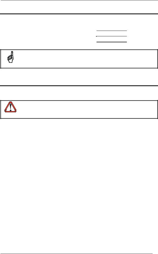
Figure A |
|
1 |
Indicator LEDs |
4 |
Compression Connectors (5) |
2 |
Cover Screws (4) |
5 |
25-pin Device Connector |
3 |
Fieldbus Interface Panel |
|
|

CBX500 INSTALLATION MANUAL
6 7 8 9
|
10 |
5 |
11 |
|
4
12
3
13
2 |
1 |
14 |
Figure B
1Power switch (ON/OFF)
2Device Chassis Grounding Selector
3Mounting Holes (2)
4I/O Extension Module Connector
5Backup Module Connector
6Indicator LEDs
7RS485 Termination Resistance Switch
8ID-NET™ Termination Resistance Switch 9 Auxiliary Port Connector
10IP65 Fieldbus Module Connector
11Standard Fieldbus Module Connector
12Spring Clamp Terminal Blocks
13Shield to Protection Earth Selector
14Power Source Selector
2

CBX500 INSTALLATION MANUAL
UPDATES AND LANGUAGE AVAILABILITY
UK/US
The latest drivers and documentation updates for this product are available on Internet. Log on to: www.automation.datalogic.com
I
Su Internet sono disponibili le versioni aggiornate di driver e documentazione di questo prodotto. Questo manuale è disponibile anche nella versione italiana.
Collegarsi a: www.automation.datalogic.com
F
Les versions mises à jour de drivers et documentation de ce produit sont disponibles sur Internet. Ce manuel est aussi disponible en version française.
Cliquez sur : www.automation.datalogic.com
D
Im Internet finden Sie die aktuellsten Versionen der Treiber und Dokumentation von diesem Produkt. Die deutschsprachige Version dieses Handbuches ist auch verfügbar.
Adresse : www.automation.datalogic.com
E
En Internet están disponibles las versiones actualizadas de los drivers y documentación de este producto. También está disponible la versión en español de este manual.
Dirección Internet : www.automation.datalogic.com
SERVICES AND SUPPORT
Datalogic provides several services as well as technical support through its website. Log on to www.automation.datalogic.com and click on the links indicated for further information including:
•PRODUCTS
Search through the links to arrive at your product page where you can download specific Manuals and
Software & Utilities:
•SERVICES & SUPPORT
-Datalogic Services - Warranty Extensions and Maintenance Agreements
-Authorised Repair Centres
•CONTACT US
E-mail form and listing of Datalogic Subsidiaries
3

CBX500 INSTALLATION MANUAL
DESCRIPTION
The CBX500 is a connection box which can be used as an accessory to facilitate system connections for installation and device replacement of several Datalogic family reading devices.
System cabling is made through spring clamp terminal blocks inside the CBX500 while the reading device is connected to the CBX500 through a 25-pin connector on the housing.
A 9-pin connector placed inside the CBX500 facilitates connection between an external PC and the auxiliary serial interface of the reading device for configuration or data monitoring.
CBX500 can also house several accessories which make the system highly flexible. These include:
•Backup Module - to backup and restore system configuration parameters making system maintenance extremely quick and easy.
•Display Module – to show reading device menu and diagnostic messages at the CBX500.
•Several Host Interface Modules - to interface the scanner with the most popular Fieldbus network types: Ethernet, Profibus; DeviceNet, etc., including IP65 protection versions.
•Mounting Adapters – to provide easy mounting to DIN rails and Bosch profiles.
ACCESSORIES
The following accessories are available on request for the CBX500:
Name |
Description |
Part Number |
BM100 |
Backup Module |
93ACC1808 |
BM150 |
Display Module |
93ACC1809 |
BM300/310 |
Profibus Module STD/IP65 |
93ACC1810, 93ACC1811 |
BM400 |
DeviceNet Module IP65 |
93ACC1814 |
BM500/510/520 |
Ethernet/IP Module STD/IP65/IP54 |
93ACC1812, 93ACC1813, 93ACC1840 |
BM600 |
CANopen Module STD |
93ACC1815 |
BM700 |
Profinet Module STD |
93ACC1816 |
BM1100 |
CC-Link Module STD |
93ACC1845 |
BM1200/1210 |
Modbus TCP STD/IP65 |
93ACC1848, 93ACC1849 |
BA100 |
DIN Rail Adapters |
93ACC1821 |
BA200 |
Bosch Adapters |
93ACC1822 |
BA900 |
Two Cable Glands Panel |
93ACC1847 |
SAFETY PRECAUTIONS
ATTENTION: READ THIS INFORMATION BEFORE INSTALLING THE PRODUCT
POWER SUPPLY
This product is intended to be installed by Qualified Personnel only.
This device is intended to be supplied by a UL Listed NEC Class 2 power source.
Total power consumption is given by adding the CBX500 power consumption to that of all the devices powered through the CBX500 (reading device, P.S., I/O). Refer to the manual of the connected devices for details about minimum/maximum supply voltage and power
consumption.
CAUTION
Each CBX500 supports only 1 single reading device + system accessories.
4
CBX500 INSTALLATION MANUAL
SUPPORTED READING DEVICE MODELS
The CBX500 can be directly connected to the following readers through the 25-pin connector illustrated in Figure A.
|
Linear Scanners |
|
2D Readers |
||
|
|
|
|
|
|
DS2100N |
DS2400N |
DS4800 |
DS6300 |
MATRIX-1000 |
MATRIX-2000 |
|
|
|
|
|
|
DS6400 |
DX6400 |
DS8100A |
DX8200A |
|
MATRIX 400 |
|
|
|
|
|
|
CBX500 is backward compatible with DS4600A, DS2100N/DS2400N (black body), and DS1100/DS2200 10-30 Vdc model reading devices using the ADP-MM1 25-pin gender changer. See the Gender Changer documentation for the relative CBX500 pinout.
NOTE
OPENING THE CBX500
To install the CBX500 or during normal maintenance, it is necessary to open it by unscrewing the four cover screws:
The CBX500 must be disconnected from the power supply during this operation.
CAUTION
5
 Loading...