


POWERSCAN 7000
PowerScan® 7000 2D Imager
Product Reference Guide

Datalogic Scanning, Inc.
959 Terry Street
Eugene, Oregon 97402
Telephone: (541) 683-5700
Fax: (541) 345-7140
An Unpublished Work - All rights reserved. No part of the contents of this documentation or the procedures
described therein may be reproduced or transmitted in any form or by any means without prior written per-
mission of Datalogic Scanning, Inc. or its subsidiaries or affiliates ("Datalogic" or “Datalogic Scanning”).
Owners of Datalogic products are hereby granted a non-exclusive, revocable license to reproduce and
transmit this documentation for the purchaser's own internal business purposes. Purchaser shall not
remove or alter any proprietary notices, including copyright notices, contained in this documentation and
shall ensure that all notices appear on any reproductions of the documentation.
Should future revisions of this manual be published, you can acquire printed versions by contacting your
Datalogic representative. Electronic versions may either be downloadable from the Datalogic website
(www.scanning.datalogic.com) or provided on appropriate media. If you visit our website and would like to
make comments or suggestions about this or other Datalogic publications, please let us know via the "Con-
tact Datalogic" page.
Disclaimer
Datalogic has taken reasonable measures to provide information in this manual that is complete and accu-
rate, however, Datalogic reserves the right to change any specification at any time without prior notice.
Datalogic is a registered trademark of Datalogic S.p.A. and the Datalogic logo is a trademark of Datalogic
S.p.A. all licensed to Datalogic Scanning, Inc. All other trademarks and trade names referred to herein are
property of their respective owners.
Paten ts
This product may be covered by one or more of the following patents: 4603262 • 4639606 • 4652750 • 4672215 • 4699447
• 4709369 • 4749879 • 4786798 • 4792666 • 4794240 • 4798943 • 4799164 • 4820911 • 4845349 • 4861972 • 4861973 •
4866257 • 4868836 • 4879456 • 4939355 • 4939356 • 4943127 • 4963719 • 4971176 • 4971177 • 4991692 • 5001406 •
5015831 • 5019697 • 5019698 • 5086879 • 5115120 • 5144118 • 5146463 • 5179270 • 5198649 • 5200597 • 5202784 •
5208449 • 5210397 • 5212371 • 5212372 • 5214270 • 5229590 • 5231293 • 5232185 • 5233169 • 5235168 • 5237161 •
5237162 • 5239165 • 5247161 • 5256864 • 5258604 • 5258699 • 5260554 • 5274219 • 5296689 • 5298728 • 5311000 •
5327451 • 5329103 • 5330370 • 5347113 • 5347121 • 5371361 • 5382783 • 5386105 • 5389917 • 5410108 • 5420410 •
5422472 • 5426507 • 5438187 • 5440110 • 5440111 • 5446271 • 5446749 • 5448050 • 5463211 • 5475206 • 5475207 •
5479011 • 5481098 • 5491328 • 5493108 • 5504350 • 5508505 • 5512740 • 5541397 • 5552593 • 5557095 • 5563402 •
5565668 • 5576531 • 5581707 • 5594231 • 5594441 • 5598070 • 5602376 • 5608201 • 5608399 • 5612529 • 5629510 •
5635699 • 5641958 • 5646391 • 5661435 • 5664231 • 5666045 • 5671374 • 5675138 • 5682028 • 5686716 • 5696370 •
5703347 • 5705802 • 5714750 • 5717194 • 5723852 • 5750976 • 5767502 • 5770847 • 5786581 • 5786585 • 5787103 •
5789732 • 5796222 • 5804809 • 5814803 • 5814804 • 5821721 • 5822343 • 5825009 • 5834708 • 5834750 • 5837983 •
5837988 • 5852286 • 5864129 • 5869827 • 5874722 • 5883370 • 5905249 • 5907147 • 5923023 • 5925868 • 5929421 •
5945670 • 5959284 • 5962838 • 5979769 • 6000619 • 6006991 • 6012639 • 6016135 • 6024284 • 6041374 • 6042012 •
6045044 • 6047889 • 6047894 • 6056198 • 6065676 • 6069696 • 6073849 • 6073851 • 6094288 • 6112993 • 6129279 •
6129282 • 6134039 • 6142376 • 6152368 • 6152372 • 6155488 • 6166375 • 6169614 • 6173894 • 6176429 • 6188500 •
6189784 • 6213397 • 6223986 • 6230975 • 6230976 • 6237852 • 6244510 • 6259545 • 6260763 • 6266175 • 6273336 •
6276605 • 6279829 • 6290134 • 6290135 • 6293467 • 6303927 • 6311895 • 6318634 • 6328216 • 6332576 • 6332577 •
6343741 • 6454168 • 6478224 • 6568598 • 6578765 • 6705527 • 6974084 • 6991169 •7051940 • AU703547 • D312631 •
D313590 • D320011 • D320012 • D323492 • D330707 • D330708 • D349109 • D350127 • D350735 • D351149 • D351150
• D352936 • D352937 • D352938 • D352939 • D358588 • D361565 • D372234 • D374630 • D374869 • D375493 •
D376357 • D377345 • D377346 • D377347 • D377348 • D388075 • D446524 • EP0256296 • EP0260155 • EP0260156 •
EP0295936 • EP0325469 • EP0349770 • EP0368254 • EP0442215 • EP0498366 • EP0531645 • EP0663643 •
EP0698251 • GB2252333 • GB2284086 • GB2301691 • GB2304954 • GB2307093 • GB2308267 • GB2308678 •
GB2319103 • GB2333163 • GB2343079 • GB2344486 • GB2345568 • GB2354340 • ISR107546 • ISR118507 •
ISR118508 • JP1962823 • JP1971216 • JP2513442 • JP2732459 • JP2829331 • JP2953593 • JP2964278 • MEX185552 •
MEX187245 • RE37166 • Other Patents Pending

Table of Contents
Chapter 1 Getting Started .........................................................1-1
About This Manual ............................................................................ 1-1
Manual Conventions .................................................................... 1-2
Resetting the Standard Product Defaults .............................................. 1-2
LED and Beeper Indications ............................................................... 1-3
Plug and Play ................................................................................... 1-4
Connecting the imager with an RS-232 Serial Port .......................... 1-4
Connecting the imager with USB ................................................... 1-5
IBM SurePos .............................................................................. 1-6
USB PC Keyboard or USB Macintosh Keyboard ................................ 1-7
USB HID ................................................................................... 1-8
USB COM Port Emulation ............................................................. 1-8
CTS/RTS Emulation ............................................................... 1-8
ACK/NAK Mode ..................................................................... 1-9
Connecting the imager in Universal Keyboard Wedge mode .............. 1-9
Chapter 2 Terminal Interfaces ..................................................2-1
Terminal ID ..................................................................................... 2-1
Supported Terminals ......................................................................... 2-2
Keyboard Country ............................................................................. 2-3
Keyboard Style ................................................................................. 2-5
Keyboard Modifiers ........................................................................... 2-7
RS-232 Modifiers .............................................................................. 2-8
RS-232 Baud Rate ...................................................................... 2-8
RS-232 Word Length: Data Bits, Stop Bits, and Parity ..................... 2-9
RS-232 Receiver Time-Out ........................................................ 2-10
RS-232 Handshaking ................................................................ 2-11
Chapter 3 Output ......................................................................3-1
Image VGA ...................................................................................... 3-1
Good Read Indicators ........................................................................ 3-1
Beeper – Good Read ................................................................... 3-1
Beeper Volume – Good Read ........................................................ 3-2
Beeper Pitch – Good Read ........................................................... 3-2
Beeper Duration – Good Read ...................................................... 3-3
LED – Good Read ....................................................................... 3-3
Number of Beeps – Good Read ..................................................... 3-3
Good Read Delay .............................................................................. 3-4
User-Specified Good Read Delay ......................................................... 3-4
Trigger Modes .................................................................................. 3-4
Manual/Serial Trigger .................................................................. 3-4
Read Time-Out ..................................................................... 3-5
Manual Trigger, Low Power..................................................... 3-5
Low Power Time-Out Timer..................................................... 3-5
Product Reference Guide i

Scan Stand Mode ..............................................................................3-7
Scan Stand Symbol .....................................................................3-7
Presentation Mode .............................................................................3-7
Presentation LED Timer ................................................................3-8
Presentation Sensitivity ...............................................................3-8
Hands Free Time-Out .........................................................................3-8
Double Read Timeout .........................................................................3-9
User-Specified Double Read Timeout ....................................................3-9
LED Power Level .............................................................................3-10
Illumination Lights ........................................................................... 3-11
Imager Time-Out ............................................................................3-11
Aimer Delay ...................................................................................3-12
User-Specified Aimer Delay ........................................................ 3-12
Aimer Modes ..................................................................................3-13
Aimer Mode Off ......................................................................... 3-13
Interlaced Mode ........................................................................3-13
Concurrent Mode ......................................................................3-13
Centering .......................................................................................3-14
Decode Search Mode .......................................................................3-16
Output Sequence Overview ...............................................................3-17
Require Output Sequence ........................................................... 3-17
Output Sequence Editor .............................................................3-18
To Add an Output Sequence .................................................. 3-18
Other Programming Selections...............................................3-19
Output Sequence Examples ........................................................ 3-19
Output Sequence Editor .............................................................3-21
Require Output Sequence ........................................................... 3-21
Multiple Symbols .............................................................................3-22
No Read ......................................................................................... 3-22
Print Weight ................................................................................... 3-23
Video Reverse ................................................................................. 3-23
Working Orientation ........................................................................3-24
Chapter 4 Data Editing ............................................................. 4-1
Prefix/Suffix Overview .......................................................................4-1
Points to Keep In Mind .................................................................4-2
To Add a Prefix or Suffix: .............................................................4-3
Example: Add a Suffix to a specific symbology...........................4-4
To Clear One or All Prefixes or Suffixes: .........................................4-4
To Add a Carriage Return Suffix to all Symbologies ..........................4-4
Prefix Selections .........................................................................4-5
Suffix Selections .........................................................................4-5
Function Code Transmit ...............................................................4-5
Intercharacter, Interfunction, and Intermessage Delays .........................4-6
Intercharacter Delay ....................................................................4-6
User Specified Intercharacter Delay ...............................................4-7
Interfunction Delay .....................................................................4-7
Intermessage Delay ....................................................................4-8
Chapter 5 Data Formatting....................................................... 5-1
Data Format Editor Introduction ..........................................................5-1
ii PowerScan® 7000 2D

To Add a Data Format ................................................................. 5-2
Other Programming Selections ..................................................... 5-3
Data Format Editor Commands ..................................................... 5-3
Send Commands ................................................................... 5-3
Move Commands................................................................... 5-4
Search Commands ................................................................ 5-4
Miscellaneous Commands ....................................................... 5-4
Data Format Editor ..................................................................... 5-5
Data Formatter .......................................................................... 5-5
Alternate Data Formats ............................................................... 5-6
Chapter 6 Symbologies .............................................................6-1
Linear Symbologies ........................................................................... 6-2
All Symbologies .......................................................................... 6-2
Message Length Description.................................................... 6-2
Code 39 ............................................................................... 6-5
Interleaved 2 of 5 ................................................................. 6-9
Code 93 ............................................................................. 6-11
Code 2 of 5 ........................................................................ 6-12
IATA Code 2 of 5................................................................. 6-13
Matrix 2 of 5....................................................................... 6-14
Code 11 ............................................................................. 6-14
Code 128 ........................................................................... 6-16
UPC-A................................................................................ 6-19
UPC-A/EAN-13
with Extended Coupon Code ................................................. 6-21
EAN/JAN-13 ....................................................................... 6-24
EAN/JAN-8 ......................................................................... 6-26
MSI ................................................................................... 6-28
Plessey Code ...................................................................... 6-29
RSS-14 .............................................................................. 6-30
RSS Limited ....................................................................... 6-30
RSS Expanded .................................................................... 6-31
PosiCode............................................................................ 6-32
Stacked Symbologies ...................................................................... 6-33
Postal Codes .................................................................................. 6-40
Trioptic Code ...................................................................... 6-33
Codablock F........................................................................ 6-33
Code 16K ........................................................................... 6-34
Code 49 ............................................................................. 6-35
PDF417.............................................................................. 6-36
MicroPDF417 ...................................................................... 6-37
EAN•UCC Composite Codes .................................................. 6-37
UPC/EAN Version................................................................. 6-38
TCIF Linked Code 39 (TLC39) ............................................... 6-39
Postnet .............................................................................. 6-40
Planet Code........................................................................ 6-41
British Post......................................................................... 6-42
Canadian Post..................................................................... 6-42
Kix (Netherlands) Post ......................................................... 6-42
Australian Post.................................................................... 6-43
Japanese Post..................................................................... 6-43
Product Reference Guide iii

China Post .......................................................................... 6-43
Korea Post .......................................................................... 6-44
QR Code ............................................................................. 6-45
Data Matrix.........................................................................6-46
MaxiCode............................................................................ 6-47
Aztec Code .........................................................................6-48
Chapter 7 Imaging Commands ................................................. 7-1
Image Snap - IMGSNP .......................................................................7-1
IMGSNP Modifiers .......................................................................7-2
Image Ship - IMGSHP ........................................................................7-4
IMGSHP Modifiers .......................................................................7-4
Intelligent Signature Capture - IMGBOX ...............................................7-9
IMGBOX Modifiers .....................................................................7-10
Chapter 8 OCR Programming ................................................... 8-1
OCR Fonts ........................................................................................8-2
OCR ..........................................................................................8-2
U.S. Currency Font ......................................................................8-3
MICR E13 B Font .........................................................................8-4
SEMI Font ..................................................................................8-4
OCR Templates .................................................................................8-5
Creating an OCR Template ...........................................................8-5
Template Characters ...................................................................8-6
To Add an OCR Template... .....................................................8-6
Character Match Sequences ....................................................8-7
Adding Spaces.......................................................................8-7
Stringing Together Multiple Formats
OCR User-Defined Variables ................................................................8-9
OCR Check Character .......................................................................8-10
OCR User-Defined Check Character ...................................................8-12
OCR ISBN Application Example .........................................................8-15
OCR Template Codes .......................................................................8-16
(Creating “Or” Statements) .....................................................8-8
Reading Multi-Row OCR ...............................................................8-9
OCR Modulo 10 Check Character .................................................8-11
OCR Modulo 36 Check Character .................................................8-11
Programming a User-Defined Check Character ..............................8-12
Weighting Options ...............................................................8-13
Exit Selections .......................................................................... 8-17
Chapter 9 Utilities .................................................................... 9-1
To Add a Test Code I.D. Prefix to All Symbologies ..................................9-1
Show Software Revision .....................................................................9-1
Show Data Format ............................................................................9-1
Resetting the Standard Product Defaults ..............................................9-2
Test Menu ........................................................................................9-2
2D PQA (Print Quality Assessment) ......................................................9-2
Power Image Configurator ..................................................................9-3
Power Image Configurator Operations ............................................9-3
Temporary Configuration Using Configurator ...................................9-4
iv PowerScan® 7000 2D

Installing Power Image Configurator from the Web ......................... 9-4
Chapter 10 Serial Programming Commands............................ 10-1
Conventions ................................................................................... 10-1
Menu Command Syntax ................................................................... 10-2
Query Commands ..................................................................... 10-2
Tag Field Usage ........................................................................ 10-3
SubTag Field Usage .................................................................. 10-3
Data Field Usage ................................................................. 10-3
Concatenation of Multiple Commands .......................................... 10-3
Responses ............................................................................... 10-3
Examples of Query Commands ................................................... 10-4
Trigger Commands ......................................................................... 10-5
Menu Commands ............................................................................ 10-6
Chapter 11 Product Specifications ..........................................11-1
Imager Product Specifications .......................................................... 11-1
Standard Cable Pinouts (Primary Interface Cables) .............................. 11-3
Serial Output .......................................................................... 11-3
USB ........................................................................................ 11-4
UKBW ..................................................................................... 11-4
Appendix A Symbologies...........................................................A-1
Symbology Chart .............................................................................. A-1
ASCII Conversion Chart (Code Page 1252) ........................................... A-4
Code Page Mapping of Printed Bar Codes ............................................. A-7
Appendix B Sample Symbols.....................................................B-1
OCR Programming Chart .................................................................... B-4
Programming Chart ........................................................................... B-5
Product Reference Guide v

vi PowerScan® 7000 2D

Chapter 1
Getting Started
The PowerScan®7000 2D imager marks a new performance level for
handheld area imagers. They deliver aggressive read rates and depths of
field on 1D, stacked linear, and matrix codes. This aggressiveness applies
even in challenging reading environments where low lighting conditions
and poor quality might make it difficult to read bar codes. You can rest
assured your investment will continue to supply years of use by reading
any bar codes you require, now or in the future.
Designed for today’s demanding commercial and industrial environments, the scanner offers superior image quality, speed, durability, and
the ability to read poor quality bar codes. The unit is comfortable to
hold, easy to use, rugged, and excellent for the most demanding applications.
About This Manual
This Product Reference Guide (PRG) provides programming instructions for the imager, plus product specifications and dimensions. For
installation, maintenance, troubleshooting and warranty information,
see the Quick Reference Guide (QRG). Copies of other publications for
this product are downloadable free of charge from the website listed on
the back cover of this manual.
The imager is factory programmed for the most common terminal and
communications settings. If you need to change these settings, programming is accomplished by scanning the bar codes in this guide.
An asterisk (*) next to an option indicates the default setting.
Product Reference Guide 1-1

Getting Started
Manual Conventions
The symbols listed below are used in this manual to notify the reader of
key issues or procedures that must be observed when using the imager:
Notes contain information necessary for properly diagnosing, repairing and operating the
imager.
NOTE
The CAUTION symbol advises you of actions
that could damage equipment or property.
CAUTION
Resetting the Standard Product
Defaults
If you aren’t sure what programming options are in your imager, or
you’ve changed some options and want the factory settings restored, scan
the Standard Product Default Settings bar code below.
Standard Product Default Settings
The chart
settings for each of the menu commands (indicated by an asterisk (*) on
the following programming pages.
1-2 PowerScan® 7000 2D
Menu Commands, starting on page 10-6 lists the factory default
LED and Beeper Indications
LED and Beeper Indications
The imager is equipped with a beeper (speaker) and two indicator LEDs;
one green and one yellow. These indicators “beep” or flash when certain
actions take place:
Some LED and Beeper indications are user-configurable for volume, pitch, quantity, duration,
enable/disable, etc. Those listed in the following
table assume the feature is enabled. See the
NOTE
Condition Green LED Beeper
Powe ring On
UKBW/RS-232 Models
(using UKBW interface)
Powe ring On
UKBW/RS-232 Models
(using RS-232 interface)
Powe ring On
All Other Models
Good Read
Error Indication
Product Reference Guide (PRG) for detailed programming information.
2 normal flashes and 2 fast flashes
(+ 1 normal flash with Smart cable)
2 normal flashes and 1 long flash
Bright Green Flash One Beep
1 - 9 Bright Green Flash(es)
Green Flash Special Beep
a
One Beep
One Beep
1 - 9 Beep(s)
a
Condition Yellow LED Beeper
Ready to Operate
a. Good Read indications are synchronous. That is, if Good Read beeps
are set via programming to five (for example), the Good Read LED will
also flash five times.
Yellow LED on steady until trigger is pulled None
Product Reference Guide 1-3
Getting Started
Plug and Play
Plug and Play bar codes provide instant imager set up for commonly
used interfaces.
After you scan one of the codes, power cycle
the host terminal to have the interface in effect.
NOTE
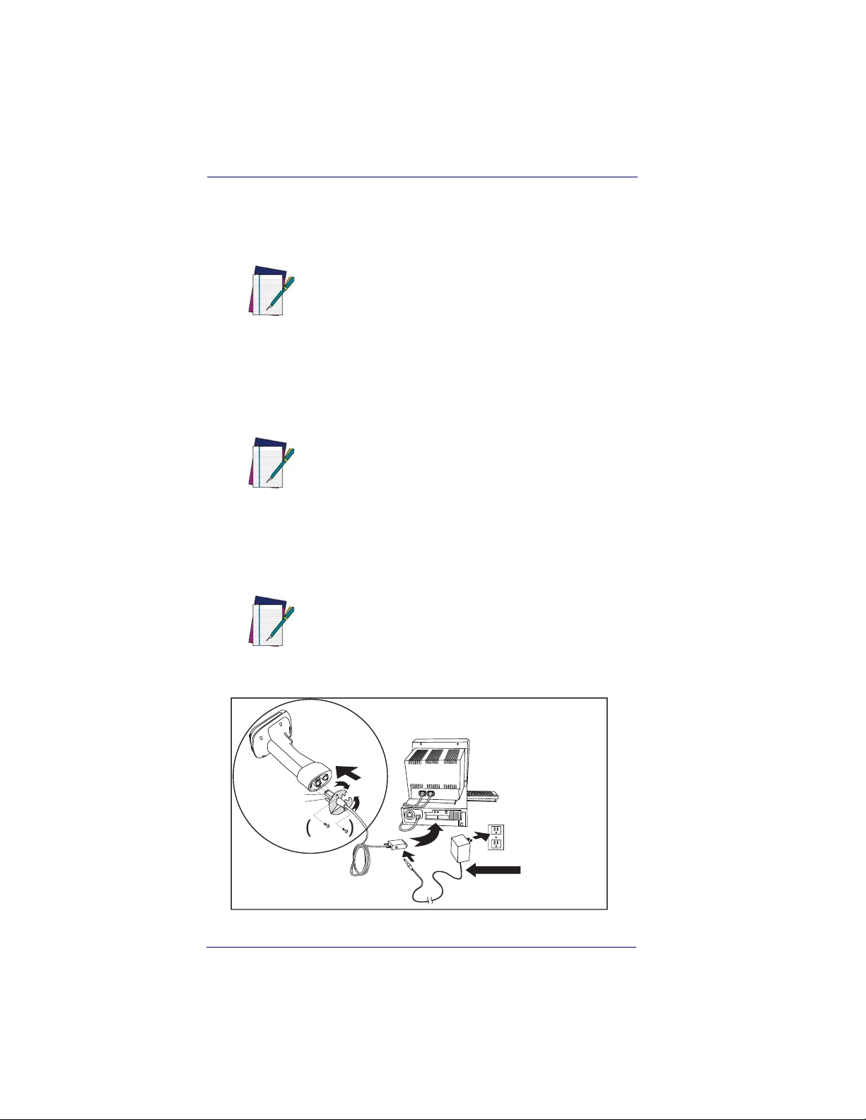
Connecting the imager with an RS-232
Serial Port
These instructions are for use with the RS-232
cable. This includes both Power Off the Terminal (P.O.T.) and external power.
NOTE
1. Turn off power to the terminal/computer.
2. Connect the appropriate interface cable to the imager.
For the imager to work properly, you must have
the correct cable for your type of terminal/computer.
NOTE
Cable Connector
Retainer Boss
Captive
Screws
1-4 PowerScan® 7000 2D
For 220-230 VAC
adapters, the
cord must be
facing down as
shown in the
illustration. If
installed upwards,
it will pose an
undue strain on the
socket outlet.

Plug and Play
3. Plug the serial connector into the serial port on your computer.
Tighten the two screws to secure the connector to the port.
4. If the terminal does not support Power Off the Terminal (P.O.T.)
connections plug the power supply into the host connector and the
AC outlet.
5. Once the imager has been fully connected, power up the computer.
All communication parameters between the imager and terminal must
match for correct data transfer through the serial port using RS-232 protocol. Scanning the RS-232 interface bar code, programs the imager for
an RS-232 interface at 115,200 baud, parity–none, 8 data bits, 1 stop
bit, and adds a suffix of a CR LF.
RS-232 Interface
Connecting the imager with USB
This interface applies to USB compatible models only.
NOTE
An imager can be connected to the USB port of a computer.
1. Connect the appropriate interface cable to the imager and to the
computer.
Cable Connector
Retainer Boss
Captive
Screws
Product Reference Guide 1-5
B
S
U

Getting Started
2. The imager beeps.
3. Verify imager operation by scanning the part number bar code
from the back cover of this manual.
The following USB “Plug and Play” codes are
supported on specific models. Refer to the
Product Reference Guide to determine if this
NOTE
interface applies to your unit.
For additional USB programming and technical information, visit the
website listed on the back cover of this manual.
IBM SurePos
Scan one of the following “Plug and Play” codes to program the imager
for IBM SurePos (USB Hand Held imager) or IBM SurePos (USB
Tabletop imager).
After scanning one of these codes, you must
power cycle the cash register
NOTE
IBM SurePos
(USB Hand Held imager) Interface
IBM SurePos
(USB Tabletop imager) Interface
1-6 PowerScan® 7000 2D

Plug and Play
Each bar code above also programs the following suffixes for each symbology:
Symbology Suffix
EAN-8 0C
EAN-13 16
UPC-A 0D
UPC-E 0A
Code 39 00 0A 0B
Interleaved 2 of 5 00 0D 0B
Code 128 00 18 0B
The following USB “Plug and Play” codes (USB
Keyboard - PC, USB Keyboard - Mac, and USB
HID) are supported on specific imager models.
Check your model type to determine if this inter-
NOTE
face applies to your unit.
USB PC Keyboard or USB Macintosh Keyboard
Scan one of the following codes to program the imager for USB PC Keyboard or USB Macintosh Keyboard. Scanning these codes adds a CR
and selects the terminal ID (USB PC Keyboard - 124, USB Macintosh
Keyboard - 125).
USB Keyboard (PC)
USB Keyboard (Mac)
Product Reference Guide 1-7

Getting Started
USB HID
Scan the following code to program the imager for USB HID bar code
imagers. Scanning this code changes the terminal ID to 131.
USB HID Bar Code imager
USB COM Port Emulation
Scan the following code to program the imager to emulate a regular RS-
®
232-based COM port. If you are using a Microsoft
Windows® PC,
you will need to download a driver from the website listed on the back
cover of this manual. The driver will use the next available COM port
®
number. Apple
Macintosh computers recognize the imager as a USB
CDC class device and automatically use a class driver. Scanning the code
below changes the terminal ID to 130.
USB COM Port Emulation
No extra configuration (e.g., baud rate) is necessary.
NOTE
CTS/RTS Emulation
On
* Off
1-8 PowerScan® 7000 2D

Plug and Play
ACK/NAK Mode
On
* Off
Reference the Product Reference Guide (PRG) for
more information about keyboard support.
NOTE
Connecting the imager in Universal Keyboard Wedge mode
The Universal Keyboard Wedge (UKBW) model allows an RS-232
transmission or Keyboard Wedge mode according to the type of cable
connected. Contact Datalogic or your dealer for cable and/or power supply part numbers.
1. Turn off power to the terminal/computer.
2. Connect the keyboard wedge interface cable to the imager.
For the imager to work properly, you must have
the correct cable for your type of terminal/computer.
NOTE
Product Reference Guide 1-9

Getting Started
3. Connect one end of the Y cable to the keyboard cable and the
other to the keyboard port on the host/computer.
Cable Connector
K
e
y
b
o
a
r
d
Retainer Boss
Captive
Screws
4. Scan the following bar code to program the imager for the UKBW
interface.
~pap232; 232CTS1 ³ .
Universal Keyboard Wedge (UKBW) Interface
1-10 PowerScan® 7000 2D

Chapter 2
Terminal Interfaces
Use this section to configure interface features
for imager models using RS-232 and USB interfaces.
NOTE
For Imager models using UKBW interfaces, do
not use this section but refer to the UKBW Connectivity Guide available for download from the
website listed on the back over of this manual.
In most cases and mainly in Concurrent Aiming
mode an external power supply is required.
Terminal ID
If your interface is not a standard PC AT, refer to Supported Terminals on
page 2-2
minal ID bar code below, then scan the numeric bar code(s) on the Pro-
gramming Chart on page B-5
your terminal ID. Scan
, and locate the Terminal ID number for your PC. Scan the Ter -
of this manual to program the Imager for
Save to save your selection.
Product Reference Guide 2-1

Terminal Interfaces
For example, an IBM AT terminal has a Terminal ID of 003. You would
scan the
page B-5
the digits (before scanning Save), scan the
on page B-4
Terminal ID bar code, then 0, 0, 3 from the Programming Chart on
of this manual, then Save. If you make an error while scanning
Discard code marked Discard
, scan the Terminal ID bar code, scan the digits, and the Save
code again.
Terminal ID
Save
After scanning one of these codes, you must
power cycle your computer.
NOTE
Supported Terminals
Terminal Model(s) Terminal ID
IBM SurePOS USB Hand Held Imager
IBM SurePOS USB Tabletop Imager
RS-232 True
RS-232 TTL 000
Serial Wedge 050
USB COM Port Emulation
USB PC Keyboard
USB Mac Keyboard
USB HID POS
a. Applies to USB models only. It is best to use the Plug and Play bar
codes located in the Quick Reference Guide, to program these interfaces, rather than scanning the terminal ID listed in this table.
b. Default for RS-232 models
2-2 PowerScan® 7000 2D
128
129
000
130
124
125
131
a
a
b
a
a
a
a

Keyboard Country
Keyboard Country
Scan the appropriate country code below to program the keyboard for
your country. As a general rule, the following characters are supported,
but need special care for countries other than the United States:
@ | $ # { } [ ] = / ‘ \ < > ~
* United States
Belgium
Brazil
Canada (French)
Czechoslovakia
Denmark
Finland (Sweden)
France
Germany/Austria
Greece
Hungary
Israel (Hebrew)
Product Reference Guide 2-3

Terminal Interfaces
Keyboard Country (continued)
Italy
Latin America
Netherlands (Dutch)
Norway
Poland
Portugal
Romania
Russia
SCS
Slovakia
Spain
Sweden
Switzerland (German)
2-4 PowerScan® 7000 2D

Keyboard Style
Keyboard Country (continued)
Tu r k e y F
Tur k e y Q
U.K.
Keyboard Style
This programs keyboard styles, such as Caps Lock and Shift Lock.
Default = Regular.
Regular is used when you normally have the Caps Lock key off.
* Regular
Caps Lock is used when you normally have the Caps Lock key on.
Caps Lock
Shift Lock is used when you normally have the Shift Lock key on (not
common to U.S. keyboards).
Shift Lock
Product Reference Guide 2-5

Terminal Interfaces
Automatic Caps Lock is used if you change the Caps Lock key on and off.
The software tracks and reflects if you have Caps Lock on or off (AT and
PS/2 only). This selection can only be used with systems that have an
LED which notes the Caps Lock status.
Automatic Caps Lock
Autocaps via NumLock bar code should be scanned in countries (e.g.,
Germany, France) where the Caps Lock key cannot be used to toggle
Caps Lock. The NumLock option works similarly to the regular Auotcaps, but uses the NumLock key to retrieve the current state of the Caps
Lock.
Autocaps via NumLock
Emulate External Keyboard should be scanned if you do not have an
external keyboard (IBM AT or equivalent).
Emulate External Keyboard
After scanning the Emulate External Keyboard
bar code, you must power cycle your computer.
NOTE
2-6 PowerScan® 7000 2D

Keyboard Modifiers
Keyboard Modifiers
This modifies special keyboard features, such as CTRL+ ASCII codes
and Turbo Mode.
Control + ASCII Mode On
The Imager sends key combinations for ASCII control characters for values 00-1F. Refer to
CTRL+ ASCII Values. Default = Off
Control + ASCII Mode On
Turbo Mode— The imager sends characters to a terminal faster. If
the terminal drops characters, do not use Turbo Mode. Default = Off
Keyboard Function Relationships on page 9-1 for
* Control + ASCII Mode Off
Turbo Mode On
* Turbo Mode Off
Numeric Keypad Mode— Sends numeric characters as if entered
from a numeric keypad. Default = Off
Numeric Keypad Mode On
* Numeric Keypad Mode Off
Product Reference Guide 2-7

Terminal Interfaces
RS-232 Modifiers
RS-232 Baud Rate
Baud Rate sends the data from the imager to the terminal at the specified
rate. The host terminal must be set for the same baud rate as the imager.
Default = 115,200.
300
600
1200
2400
4800
9600
19200
38400
57,600
*115,200
2-8 PowerScan® 7000 2D

RS-232 Modifiers
RS-232 Word Length: Data Bits, Stop Bits,
and Parity
Data Bits sets the word length at 7 or 8 bits of data per character. If an
application requires only ASCII Hex characters 0 through 7F decimal
(text, digits, and punctuation), select 7 data bits. For applications which
require use of the full ASCII set, select 8 data bits per character. Default
= 8.
Stop Bits sets the stop bits at 1 or 2. Default = 1.
Parity provides a means of checking character bit patterns for validity.
Default = None.
7 Data, 1 Stop, Parity Even
7 Data, 1 Stop, Parity None
7 Data, 1 Stop, Parity Odd
7 Data, 2 Stop, Parity Even
7 Data, 2 Stop Parity None
7 Data, 2 Stop, Parity Odd
8 Data, 1 Stop, Parity Even
* 8 Data, 1 Stop, Parity None
8 Data, 1 Stop, Parity Odd
Product Reference Guide 2-9

Terminal Interfaces
RS-232 Receiver Time-Out
The unit stays awake to receive data until the RS-232 Receiver TimeOut expires. A manual or serial trigger resets the time-out. When an
RS-232 receiver is sleeping, a character may be sent to wake up the
receiver and reset the time-out. A transaction on the CTS line will also
wake up the receiver. The receiver takes 300 milliseconds to completely
come up. Change the RS-232 receiver time-out by scanning the bar
code below, then scanning digits from the
5
of this manual, then scanning Save. The range is 0 to 300 seconds.
Default = 0 seconds (no time-out - always on).
RS-232 Receiver Time-Out
Programming Chart on page B-
2-10 PowerScan® 7000 2D

RS-232 Modifiers
RS-232 Handshaking
RS-232 handshaking is a set of rules concerning the exchange of data
between serially communicating devices.
If using RTS/CTS handshaking, the imager issues an active RTS signal
to the receiving device. The imager waits to send its data until it detects
an active CTS signal from the receiving device. The imager then sends
its data while checking the CTS signal before the transmission of each
data character. If an inactive CTS signal is detected at any time, the
imager halts transmission until it detects another active CTS signal.
When the imager has finished transmitting data, it issues an inactive
RTS signal to the receiving device. Default = RTS/CTS Off, XON/XOFF
Off, and ACK/NAK Off.
RTS/CTS On
* RTS/CTS Off
XON/XOFF On
* XON/OFF Off
ACK/NAK On
* ACK/NAK Off
Product Reference Guide 2-11

Terminal Interfaces
NOTES
2-12 PowerScan® 7000 2D
 Loading...