

Page 1
Matrix 220™
Product Reference Guide
Image Based Reader
Page 2

Datalogic S.r.l.
Via S. Vitalino, 13
40012 Calderara di Reno — Italy
Tel. +39 051 3147011
Fax +39 051 3147205
Matrix 220™ Product Reference Guide
Original Instructions
Ed.: 11/2018
This manual refers to software version 1.6.0 and later.
© 2018 Datalogic S.p.A. and/or its affiliates
ALL RIGHTS RESERVED. Without limiting the rights under copyright, no part of this docu-
mentation may be reproduced, stored in or introduced into a retrieval system, or transmitted
in any form or by any means, or for any purpose, without the express written permission of
Datalogic S.p.A. and/or its affiliates.
Datalogic and the Datalogic logo are registered trademarks of Datalogic S.p.A. in many countries, including the U.S.A. and the E.U.
Matrix 220, ID-NET, DL.CODE and X-PRESS are trademarks of Datalogic S.p.A.and/or its affiliates. All other trademarks and bands are property of their respective owners.
Datalogic shall not be liable for technical or editorial errors or omissions contained herein, nor
for incidental or consequential damages resulting from the use of this material.
Page 3

Table Of Contents
REFERENCES ........................................................................................................................................................................VII
Reference Documentation ............................................................................................................................................................ vii
Support Through The Website ...................................................................................................................................................... vii
Patents ............................................................................................................................................................................................ vii
Conventions ................................................................................................................................................................................... viii
COMPLIANCE.........................................................................................................................................................................IX
General ..............................................................................................................................................................................................ix
Power Supply ....................................................................................................................................................................................ix
EMC Compliance ...............................................................................................................................................................................ix
CE Compliance ..................................................................................................................................................................................ix
FCC Compliance .................................................................................................................................................................................x
EAC Compliance .................................................................................................................................................................................x
LED Safety ..........................................................................................................................................................................................x
HANDLING..............................................................................................................................................................................XI
GENERAL VIEW ...................................................................................................................................................................XIII
RAPID CONFIGURATION ....................................................................................................................................................... 1
Step 1 - Connect the System .......................................................................................................................................................... 1
CBX100/CBX500 Pinout for Matrix 220 ......................................................................................................................... 2
Step 2 - Mount and Position the Reader ....................................................................................................................................... 3
Step 3 - Aim and Autofocus the Reader ........................................................................................................................................ 5
Step 4 - X-PRESS Configuration ..................................................................................................................................................... 6
Aim ..................................................................................................................................................................................... 6
Setup ................................................................................................................................................................................. 6
Learn .................................................................................................................................................................................. 6
Reset Reader to Factory Default Environment (Optional) ........................................................................................... 7
Step 5 - Installing DL.CODE Configuration Program .................................................................................................................... 8
Device Discovery .............................................................................................................................................................. 8
Step 6 - Device Configuration ....................................................................................................................................................... 11
Automatic or Advanced Setup ...................................................................................................................................... 11
Automatic Setup ............................................................................................................................................................ 12
Advanced Setup .............................................................................................................................................................. 15
Reading Phase ................................................................................................................................................................ 23
Good Read Setup ............................................................................................................................................................ 24
Data Formatting ............................................................................................................................................................. 25
Output Setup .................................................................................................................................................................. 26
Step 7 - Test Mode ......................................................................................................................................................................... 27
Advanced Reader Configuration ................................................................................................................................................... 28
Host Mode Programming ...................................................................................................................................................... 28
INTRODUCTION.................................................................................................................................................................... 29
Product Description ....................................................................................................................................................................... 29
Standard Application Program ..................................................................................................................................... 30
Programmability ............................................................................................................................................................ 30
Excellent Performance .................................................................................................................................................. 31
Ease of Setup .................................................................................................................................................................. 31
Ease of Use ..................................................................................................................................................................... 31
Flexible Solution ............................................................................................................................................................. 31
Versatility ........................................................................................................................................................................ 31
Industrial Strength ......................................................................................................................................................... 32
Product Reference Guide iii
Page 4

Indicator and Keypad Button .........................................................................................................................................................32
Aiming System ................................................................................................................................................................................34
LED Spots .........................................................................................................................................................................................34
ID-NET ..............................................................................................................................................................................................35
X-PRESS Human Machine Interface .............................................................................................................................................36
X-PRESS Functions ................................................................................................................................................................37
Test Mode ........................................................................................................................................................................37
Focus/Aim .......................................................................................................................................................................38
Setup ................................................................................................................................................................................38
Learn ................................................................................................................................................................................38
Diagnostic Indication ..............................................................................................................................................................39
Model Description ...........................................................................................................................................................................39
Internal Lighting Systems ......................................................................................................................................................40
Accessories ......................................................................................................................................................................................40
Application Examples .....................................................................................................................................................................42
Document Handling ................................................................................................................................................................42
Deformed or Overprinted Code Reading ..............................................................................................................................42
Direct Part Marking ................................................................................................................................................................43
Ink-Jet Printing Technology ...................................................................................................................................................43
Laser Marking/Etching Technology ......................................................................................................................................44
INSTALLATION..................................................................................................................................................................... 45
Package Contents ...........................................................................................................................................................................45
Mechanical Dimensions .................................................................................................................................................................46
Mounting And Positioning Matrix 220 .........................................................................................................................................51
Mounting Accessory Covers ..........................................................................................................................................................54
ELECTRICAL CONNECTIONS............................................................................................................................................... 55
CBX Connection Box Pinout ...........................................................................................................................................................55
Power Supply ...................................................................................................................................................................................57
Standard Models .....................................................................................................................................................................57
Power Over Ethernet (PoE) Models ......................................................................................................................................57
Main Serial Interface ......................................................................................................................................................................58
RS232 Interface .......................................................................................................................................................................58
RS422 Full Duplex Interface ...................................................................................................................................................59
ID-NET Interface .............................................................................................................................................................................60
ID-NET Cables ..........................................................................................................................................................................60
ID-NET Response Time ..........................................................................................................................................................61
ID-NET Network Termination ................................................................................................................................................62
ID-NET Connection Diagrams ................................................................................................................................................62
Auxiliary RS232 Interface ...............................................................................................................................................................65
Inputs ...............................................................................................................................................................................................66
External Trigger Input Connections Using Matrix 220 Power ............................................................................................67
External Trigger Input Connections Using External Power ................................................................................................69
Input 2 Connections Using Matrix 220 Power .....................................................................................................................69
Input 2 Connections Using External Power .........................................................................................................................70
Input 3 Connections (CBX500 Only) ......................................................................................................................................71
Outputs ............................................................................................................................................................................................71
Output 1 and 2 Connections Using Matrix 220 Power ........................................................................................................72
Output 3 Connections Using Matrix 220 Power (CBX500 Only) .........................................................................................74
On-Board Ethernet Interface .........................................................................................................................................................75
User Interface - Serial Host ...........................................................................................................................................................75
TYPICAL LAYOUTS............................................................................................................................................................... 76
Ethernet Connection .......................................................................................................................................................................77
Serial Connection ............................................................................................................................................................................79
Fieldbus Connection .......................................................................................................................................................................80
Pass-Through ..................................................................................................................................................................................81
ID-NET Multidata Network (Pass-Through) ................................................................................................................................82
ID-NET Synchronized Network ......................................................................................................................................................83
READING FEATURES........................................................................................................................................................... 86
FOV Calculation ...............................................................................................................................................................................86
iv
Matrix 220
Page 5

Global FOV Diagrams ..................................................................................................................................................................... 87
7 mm Models (38°Horizontal View Angle) .......................................................................................................................... 88
12 mm Models (24° Horizontal View Angle) ....................................................................................................................... 89
Reading Diagrams .......................................................................................................................................................................... 90
Matrix 220 (7 mm models) 1D Codes ................................................................................................................................... 91
Matrix 220 (7 mm models) 2D Codes ................................................................................................................................... 93
Matrix 220 (12 mm models) 1D Codes ................................................................................................................................. 94
Matrix 220 (12 mm models) 2D Codes ................................................................................................................................. 96
Maximum Line Speed and Exposure Time Calculations ............................................................................................................ 97
SOFTWARE CONFIGURATION............................................................................................................................................. 99
DL.CODE System Requirements ................................................................................................................................................... 99
Reader Configuration ................................................................................................................................................................... 100
Auto-Calibration ................................................................................................................................................................... 100
Manual Calibration ............................................................................................................................................................... 102
Under-exposure ........................................................................................................................................................... 102
Over-exposure .............................................................................................................................................................. 103
Moving code out of the Field of View ......................................................................................................................... 104
Multi Image Acquisition Settings ............................................................................................................................................... 105
Automatic Image Settings Selection .................................................................................................................................. 106
External Image Settings Selection ..................................................................................................................................... 107
Image Cropping ............................................................................................................................................................................ 109
Direct Part Marking Applications ............................................................................................................................................... 112
Matrix 220 Recommended Illumination for DPM ............................................................................................................. 113
Illumination Examples for DPM Applications ................................................................................................................... 114
Code Positioning with Respect to Illumination ........................................................................................................ 114
Code Contrast ............................................................................................................................................................... 115
Image Filter ........................................................................................................................................................................... 116
Pass-Through Configurations .................................................................................................................................................... 120
Internal Network Configurations ............................................................................................................................................... 122
Master Configuration ........................................................................................................................................................... 122
Multidata ID-NET Network Configurations ....................................................................................................................... 125
Synchronized ID-NET Network Configurations ................................................................................................................ 130
Verify Master/Slave Synchronized Configuration ............................................................................................................ 134
Backup and Restore Through DL.CODE ..................................................................................................................................... 137
Backup ................................................................................................................................................................................... 138
Restore .................................................................................................................................................................................. 139
Replacement ......................................................................................................................................................................... 140
Restore Defaults .......................................................................................................................................................................... 140
Restore Default Startup Configuration .............................................................................................................................. 140
Restore Default Environment ............................................................................................................................................. 141
Restore Factory Defaults .................................................................................................................................................... 142
Diagnostic Alarms ........................................................................................................................................................................ 142
Statistics ....................................................................................................................................................................................... 143
BM150 Display Module Configuration and Messages ............................................................................................................. 144
Configuration Through DL.CODE ........................................................................................................................................ 144
Accessing the HMI Interface Through Keypad and Display Menu .................................................................................. 145
Display Messages ................................................................................................................................................................ 147
BM150 Backup and Restore Procedure ............................................................................................................................. 150
MAINTENANCE.................................................................................................................................................................. 152
Cleaning ......................................................................................................................................................................................... 152
TROUBLESHOOTING.......................................................................................................................................................... 153
General Guidelines ....................................................................................................................................................................... 153
TECHNICAL FEATURES...................................................................................................................................................... 156
Electrical Features ....................................................................................................................................................................... 156
Optical Features ........................................................................................................................................................................... 157
Environmental Features .............................................................................................................................................................. 157
Physical Features ......................................................................................................................................................................... 158
Software Features ....................................................................................................................................................................... 158
ALTERNATIVE CONNECTIONS ...................................................................................................................... 159
Product Reference Guide v
Page 6

Power, Com and I/O Connector for Standard Models ............................................................................................................. 159
Com and Trigger Connector for PoE Models ............................................................................................................................. 160
On-Board Ethernet Connector .................................................................................................................................................... 161
Standard Models .................................................................................................................................................................. 161
Power over Ethernet (PoE) Models .................................................................................................................................... 162
ID-NET Network Termination ..................................................................................................................................................... 162
Inputs ............................................................................................................................................................................................ 163
Outputs ......................................................................................................................................................................................... 163
User Interface - Serial Host ........................................................................................................................................................ 166
GLOSSARY........................................................................................................................................................................... 167
vi
Matrix 220
Page 7

Reference Documentation
The documentation related to the Matrix 220 is listed below:
• This Product Reference Guide
• DL.CODE User’s Manual
• DL.CODE Help Online
Support Through The Website
Datalogic provides several services as well as technical support through its website. Log on to www.datalogic.com and click on the SUPPORT link which gives
you access to:
• Downloads by selecting your product model from the dropdown list in the
Search by Product field for specific Data Sheets, Manuals, Software & Utili
ties, and Drawings;
• Repair Program for On-Line Return Material Authorizations (RMAs) plus
RepairCenter contact information;
• Customer Service containing details about Maintenance Agreements;
• Technical Support through email or phone.
References
-
Patents
See www.patents.datalogic.com for patent list.
This product is covered by one or more of the following patents:
Design patents: EP004735694
Utility patents: EP0996284B1, EP0999514B1, EP1014292B1, EP1128315B1,
EP1396811B1, EP1413971B1, EP2517148B1, EP2649555B1, JP4435343B2,
JP4571258B2, US6512218, US6616039, US6808114, US6997385, US7053954,
US7387246, US7433590, US8058600, US8368000, US8888003, US8915443,
US9268982, US9430689, US9798948, ZL200980163411.X
Product Reference Guide vii
Page 8

References
Conventions
This symbol alerts the user they are about to perform a dangerous action that could
result in personal injury as well as damage to the device if not performed correctly.
Examples involve exposure to dangerous levels of voltage or electrical shock hazards.
WARNING
CAUTION
NOTE
This symbol identifies a hazard or procedure
cause equipment damage. It is also used to bring the user’s attention to details that
are considered IMPORTANT.
This symbol draws attention to details or pro
maintaining, or enhancing the performance of the hardware or software being discussed.
that, if incorrectly performed, could
cedures that may be useful in improving,
viii
Matrix 220
Page 9

General
For installation, use and maintenance it is not necessary to open the reader.
Only connect Ethernet and dataport connections to a network which has routing
only within the plant or building and no routing outside the plant or building
Power Supply
ATTENTION: READ THIS INFORMATION BEFORE INSTALLING THE PRODUCT
This product is intended to be installed by Qualified Personnel only.
This product is intended to be connected to a UL Listed Computer (LPS or “Class
2”) which supplies power directly to the reader, or a UL Listed Direct Plug-in
Power Unit (rated 10 to 30 V, minimum 1 A) marked LPS or “Class 2”, or Power
over Ethernet source Device supplied by UL Listed Direct Plug-in Power Unit
marked LPS or “Class 2”.
Compliance
EMC Compliance
In order to meet the EMC requirements:
• connect reader chassis to the plant earth ground by means of a flat copper
braid shorter than 100
• connect pin "Earth" of the CBX connection box to a good Earth Ground;
• for direct connections, connect your cable shield to the locking ring nut of
the connector.
CE Compliance
CE marking states the compliance of the product with essential requirements
listed in the applicable European directive. Since the directives and applicable
standards are subject to continuous updates, and since Datalogic promptly
adopts these updates, therefore the EU declaration of conformity is a living doc
ument. The EU declaration of conformity is available for competent authorities
and customers through Datalogic commercial reference contacts. Since April
20th, 2016 the main European directives applicable to Datalogic products
require inclusion of an adequate analysis and assessment of the risk(s). This
evaluation was carried out in relation to the applicable points of the standards
listed in the Declaration of Conformity. Datalogic products are mainly designed
for integration purposes into more complex systems. For this reason it is under
mm;
-
Product Reference Guide ix
Page 10

Compliance
the responsibility of the system integrator to do a new risk assessment regarding
the final installation.
Warning
This is a Class A product. In a domestic environment this product may cause
radio interference in which case the user may be required to take adequate mea
sures.
FCC Compliance
Modifications or changes to this equipment without the expressed written
approval of Datalogic could void the authority to use the equipment.
This device complies with PART 15 of the FCC Rules. Operation is subject to the
following two conditions: (1) This device may not cause harmful interference,
and (2) this device must accept any interference received, including interference
which may cause undesired operation.
This equipment has been tested and found to comply with the limits for a Class
A digital device, pursuant to part 15 of the FCC Rules. These limits are designed
to provide reasonable protection against harmful interference when the equip
ment is operated in a commercial environment. This equipment generates, uses,
and can radiate radio frequency energy and, if not installed and used in accor
dance with the instruction manual, may cause harmful interference to radio
communications. Operation of this equipment in a residential area is likely to
cause harmful interference in which case the user will be required to correct the
interference at his/her own expense.
-
-
-
EAC Compliance
Customs Union:
The CU Conformity certification has been achieved; this allows the Product to
bear the Eurasian Mark of conformity.
LED Safety
LED emission according to EN 62471.
x
Matrix 220
Page 11

Handling
The Matrix 220 is designed to be used in an industrial environment and is built
to withstand vibration and shock when correctly installed, however it is also a
precision product and therefore before and during installation it must be handled correctly to avoid damage.
• avoid that the readers are dropped (exceeding
• do not fine tune the positioning by striking the reader or bracket.
shock limits)
Product Reference Guide xi
Page 12

Handling
• do not weld the reader into position which can cause electrostatic, heat or
reading window damage.
• do not spray paint near the reader which can cause reading window damage.
xii
Matrix 220
Page 13

Standard Model PoE Model
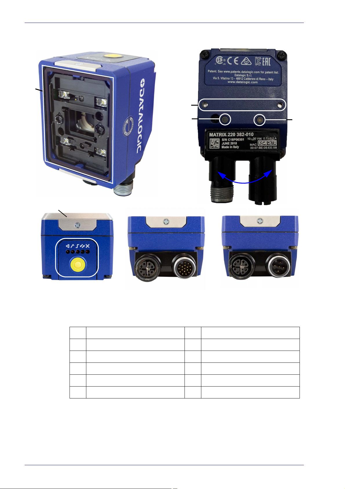
General View
General View of DPM Models
Reading Window Accessory Window Cover
Mounting Holes (2) X-PRESS Interface
Power On LED Ethernet Connector
Ethernet Connection LED Power, COM, I/O Connector
90° Rotating Connector Block Power Over Ethern
COM, Trigger Connector
et Connector
Product Reference Guide xiii
Page 14
Standard Model PoE Model
General View
General View of Standard Models
Reading Window Accessory Window Cover
Mounting Holes (2) X-PRESS Interface
Power On LED Ethernet Connector
Ethernet Connection LED Power, COM, I/O Connector
90° Rotating Connector Block Power Over Ethernet Connector
COM, Trigger Connector
xiv
Matrix 220
Page 15
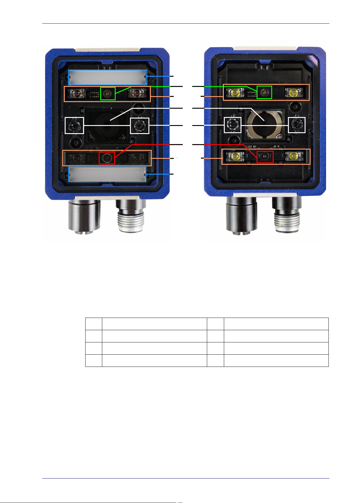
DPM Models Standard Models
General View
Lens Non Polarized Illuminator
LED Aiming System Polarized Illuminator
Red Spot (No Read) Diffused Illuminators
Green Spot (Good Read) Standard Illuminators (Top/Bottom)
Reading Window Details
Product Reference Guide xv
Page 16
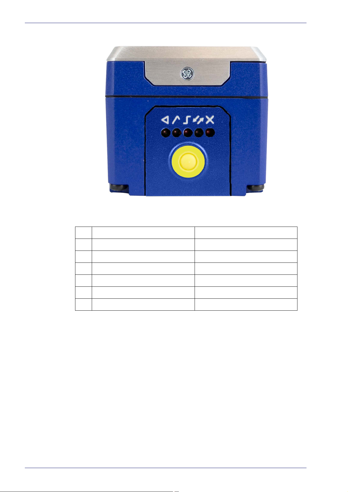
General View
X-PRESS Interface Details
Normal Operation X-PRESS Configuration
Ready Learn
Good Setup
Trigger Aim
COM Test
Status
Push-button
xvi
Matrix 220
Page 17
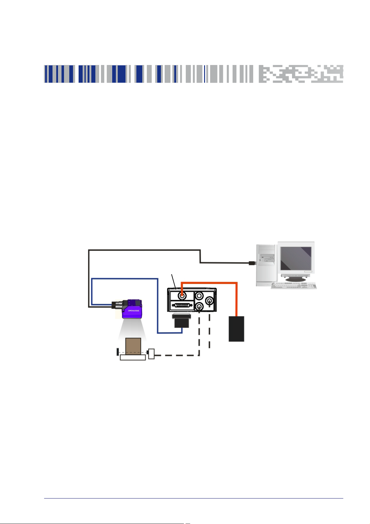
Step 1 - Connect the System
PG6000
Host
CAB-DSxx-S
Matrix 220
CAB-ETH-M0x
CBX
Ethernet Interface
Auxiliary Serial Interface (RS232 - Data Monitor)
External Trigger (for One Shot or Phase Mode)
Alone
To connect the system in a Stand Alone configuration, you need the hardware
indicated in
Ethernet interface. Data can also be transmitted on the RS232 main and/or
auxiliary interface independently from the Ethernet interface selection.
When One Shot or Phase Mode Operating mode is used, the reader is activated
an External Trigger (photoelectric sensor) when the object enters its reading
by
zone.
Figure 1. In this layout the data is transmitted to the Host on the
Chapter 1
Rapid Configuration
Figure 1 - Matrix 220 in Stand Alone Layout
Product Reference Guide 1
Page 18

Rapid Configuration
CBX100/CBX500 Pinout for Matrix 220
The table below gives the pinout of the CBX100/CBX500 terminal block
connectors. Use this pinout when the Matrix 220 reader is connected by means
of the CBX100/CBX500:
Group Label Description
Input Power Vdc Power Supply Input Voltage +
GND Power Supply Input Voltage -
Earth Protection Earth Ground
Inputs +V Power Source - External Trigger
I1A External Trigger A (pola
I1B External Trigger B (polarity insensitive)
-V Power Reference - External Trigger
I +V Power Source - Inputs
I2A Input 2 A (polarity insensitive)
I2B Input 2 B (polarity insensitive)
-V Power Reference - Inputs
Outputs +V Power Source - Outputs
-V Power Reference - Outputs
O1+ Output 1 + opto-isolated and polarity sensitive
O1- Output 1 - opto-isolated and polarity sensitive
O2+ Output 2 + opto-isolated and polarity sensitive
O2- Output 2 - opto-isolated and polarity sensitive
O3A Output 3 - opto-isolated (only available through CBX500)
Auxiliary Interface TX Transmit Data
rity insensitive)
RX Receive Data
SGND Auxiliary Interface Signal Ground
ID-NET REF Network Reference
ID+ ID-NET network data +
ID- ID-NET network data -
Shield Network Cable Shield
Main Interface
* Do not leave floating, see "RS422 Full Duplex Interface" on page 59 for connection
RS232 RS422 Full Duplex
TX TX+
RX *RX+
- TX-
- *RX-
SGND SGND
details.
2
Matrix 220
Page 19
Step 2 - Mount and Position the Reader
Skew
Tilt
Do not connect GND, SGND and REF to different (external) ground references. GND,
SGND and REF are internally connected through filtering circuitry which can be permanently damaged if subjected to voltage drops over 0.8 Vdc.
CAUTION
Step 2 - Mount and Position the Reader
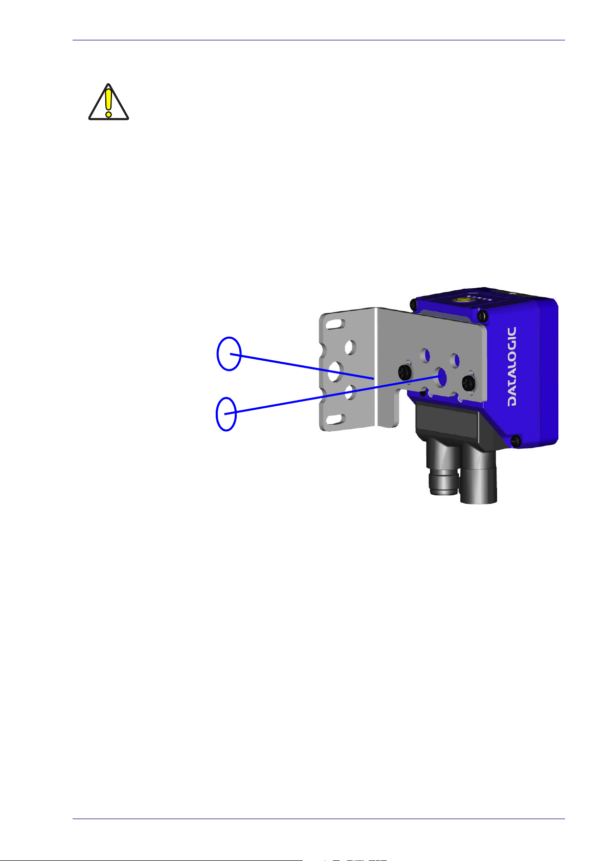
1. To mount the Matrix 220, use the mounting brackets to obtain the most
suitable position for the reader. The most common mounting configuration
is shown in the figure below.
Figure 2 - Positioning with Mounting Bracket
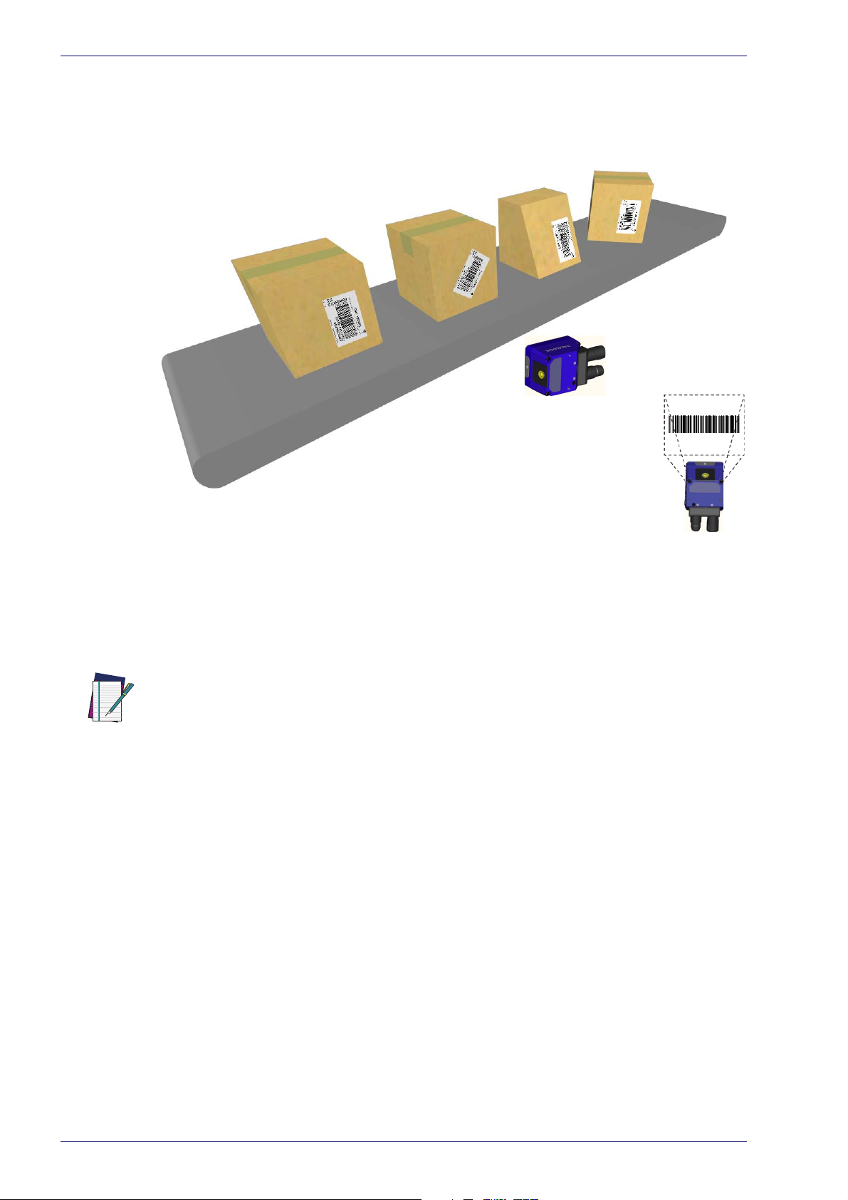
2. When mounting the Matrix 220 take into consideration these three ideal
label position angles: Pitch or Skew 10° to 20° and Tilt 0°, although the
reader can read a code at any tilt angle provided the code fits into the Field
Of View (FOV).
Product Reference Guide 3
Page 20
FOV
V
FOV
H
No Pitch,
Tilt or Skew
Pitch
Minimize
Tilt
any angle
inside FOV
Skew
assure at least 10°
Rapid Configuration
NOTE
Figure 3 - Pitch, Skew and Tilt References
3. Refer to the reading diagrams in Chapter 6, to determine the distance your
reader should be positioned at.
Rapid Configuration of the Matrix 220 reader can be made either through the XPRESS interface (steps 3-4) which requires no PC connection, or by using the DL.CODE
Configuration Program (steps 5-6). Select the procedure according to your needs.
4
Matrix 220
Page 21

Step 3 - Aim and Autofocus the Reader
Matrix 220 provides a built-in LED aiming system to aid reader positioning. The
autofocus feature is also incorporated into this function. The aiming system is
accessed through the X-PRESS Interface.
Step 3 - Aim and Autofocus the Reader
1. Power the reader on. During the reader st
the LEDs blink for one second. On the reverse side of the reader near the
bracket, the “POWER ON” LED (blue) indicates the reader is correctly powered.
2. Place the Gr
reading distance for your application. See "Gl
87 for reference.
Enter the Aim/Autofocus function by pressing and holding the X-PRESS
3.
push button until the Aim LED is on.
4. Release the button to enter the Aim function. The aiming system turns on,
and th
until the procedure is completed.
Within 3 seconds (before the reader flashes), center one of the larger codes
betwe
procedure).
The Autofocus procedure ends when the Reading Distance and PPI values
are succes
and Matrix 220 emits 3 high pitched beeps.
If the Autofocus cannot be reached after a timeout of about 3 (three) minutes Matrix 220 will exit without saving the parame
LED will stop blinking and in this case Matrix 220 emits a long low pitched
beep.
en the aiming system indicators (the code must not move during this
ade A Barcode Test Chart in front of the reader at the correct
e Autofocus procedure begins, see Figure 4 -. The Aim LED will blink
sfully saved in the reader memory, the Aim LED will stop blinking
artup (reset or restart phase), all
obal FOV Diagrams" on page
ters to memory, the Aim
Figure 4 -
X-PRESS Interface; Aim/Autofocus Function
You can exit the Aim/Autofocus function at any time by pressing the X-PRESS push
button once. After a short delay the autofocus procedure is cancelled and the aiming
indicators turn off.
NOTE
Product Reference Guide 5
Page 22

Rapid Configuration
Step 4 - X-PRESS Configuration
Once Matrix 220 is focused at the correct reading distance, you must configure it
for optimal code reading relative to your application.
Aim
1. Enter the Aim function by pressing and holding the X-PRESS push button
until the Aim LED is on.
2. Release the button to enter the Aim function. The aiming system turns on.
3. Sel
ect a single code from your application. Position the code at the center of
the FOV (equidistant from the aiming indicators.
The reader may start flashing and try to perform autofocus however this will
h
ave no effect on the application specific code; it can be ignored.
Exit the Aim function by pressing the X-PRESS push button once.
short delay the Aim function is cancelled and the aiming indicators turn off.
After a
Setup
4. Enter the Setup function by pressing and holding the X-PRESS push button
until the Setup LED is on.
5. Release the button to enter the Setup function. The Setup LED will blink
until the pro
The Setup procedure ends when the Image Acquisition parameters are successfully saved in the reader memory, the Setup LED will stop blinking and
ix 220 emits 3 high pitched beeps.
Matr
If the calibration cannot be reached after a timeout of about 5 (five) seconds
trix 220 will exit without saving the parameters to memory, the Setup
Ma
LED will stop blinking and in this case Matrix 220 emits a long low pitched
beep.
cedure is completed.
Learn
6. Enter the Learn function by pressing and holding the X-PRESS push button
until the Learn LED is on.
7. Release the button to enter the Learn function. The Learn LED will blink
until the pro
The Learn procedure ends when the Image Processing and Decoding parameters are successfully saved in the reader memory, the Green Spot is activated, the Learn LED will stop blinking and Matrix 220 emits 3 high pitched
beeps
1. The Code Autolearn procedure will not recognize the following symbologies: Pharmacode, MSI,
1
Standard 2 of 5, Matrix 2 of 5.
6
cedure is completed.
.
Matrix 220
Page 23

NOTE
NOTE
Step 4 - X-PRESS Configuration
If the autolearning cannot be reached after a timeout of about 3 (three)
minutes Matrix 220 will exit without saving the parameters to memory, the
Learn LED will stop blinking and in this case Matrix 220 emits a long low
pitched beep.
The Grade A Barcode Test Chart cannot be used to set the Code 128 symbology (even
though the reader successfully reads the code). Use the application specific code if
you need to set this symbology.
When using X-PRESS or the BM150 menu to perform Auto-Learn, only a single code
can be configured (successive Learns will substitute the current code). To configure
multiple codes, use the DL.CODE Auto-Learn procedure.
NOTE
NOTE
You can always exit from any X-PRESS function at any time by pressing the X-PRESS
push button once. After a short delay the procedure is cancelled.
If you have used this procedure to configure
Matrix 220, go to step 7.
Reset Reader to Factory Default Environment (Optional)
If it ever becomes necessary to reset the reader’s Environment parameters to
their factory default values, you can perform this procedure by holding the XPRESS push button pressed while powering up the reader. You must keep the XPRESS push button pressed until all LEDs blink simultaneously for about 3
seconds. Release and re-press the button during this LED blinking sequence.
All the device’s Environment parameters are reset including the default IP
ddress. The Matrix 220 emits 3 high pitched beeps and after a few seconds
A
enters run mode.
Any previously saved configurations on the device will remain in memory, but
the De
fault configuration is set as the startup configuration.
Product Reference Guide 7
Page 24

Rapid Configuration
If you release the button while the LEDs are all on continuously (after the blinking
phase), the reader will enter the Loader program sequence and the LEDs will begin to
cycle through various patterns. Just cycle power to return to run mode.
NOTE
Step 5 - Installing DL.CODE Configuration Program
CAUTION
DL.CODE does not currently support Windows
and/or PLCs).
DL.CODE is a Datalogic reader configuration tool providing several important
advantages:
• Intuitive Graphical User Interface for rapid configuration
• Defined configuration directly stored in the reader
• Discovery and IP address setting features to facilitate remote configuration
• Device Monitoring
To install DL.CODE:
1. On the PC that will be used for configuration, (running Windows 7, 8.1, or 10),
ownload the DL.CODE mini-DVD.zip file. Extract the files maintaining the
d
folder structure and run the start.hta file to access the installation pop-up.
Click on the Install DL.CODE link to run the installation program and follow the
installation procedure.
Embedded (often used in industrial PCs
To perform a “silent” installation
NOTE
2. When the installation is complete the DL.CODE entry is created in the
Start>Programs bar under “Datalogic” as well as a desktop icon. Doubleclick the desktop icon to run it.
This configuration procedure assumes a l
connected to a factory default reader through the Ethernet port.
(without user input), see the DL.CODE User’s Guide.
aptop computer, running DL.CODE, is
Device Discovery
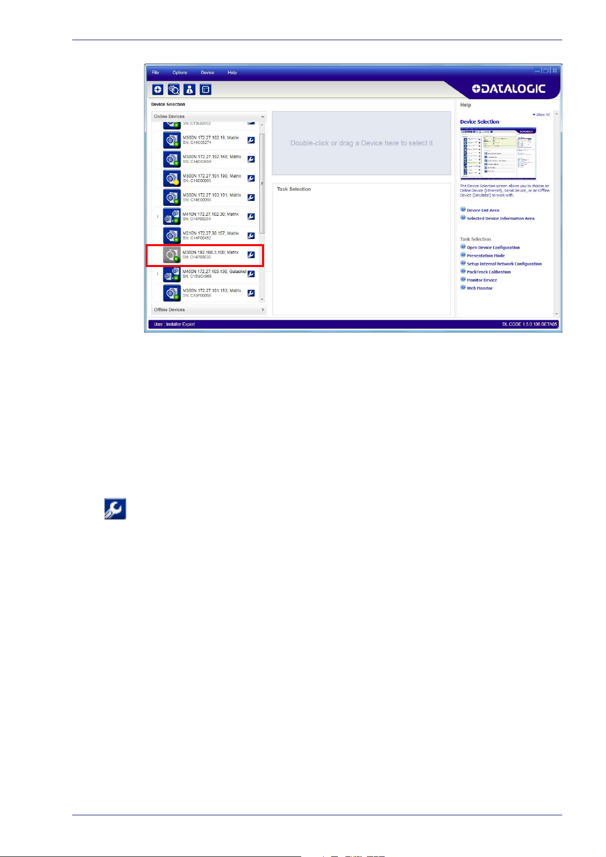
The User Interface opens and displays a list of all the devices belonging to the
Local Area Network. DL.CODE has a discovery feature to accomplish this task.
8
Matrix 220
Page 25
Step 5 - Installing DL.CODE Configuration Program
Figure 5 - Device Discovery
The discovery feature will also show devices not belonging to the LAN and
display them in grey (see Figure 5 -).
3. First the device must be added to the LAN by aligning
network. The network administrator should provide valid LAN address(es).
4. Find your device in the list by matching its serial number (SN) then click on
he device wrench icon
t
dow.
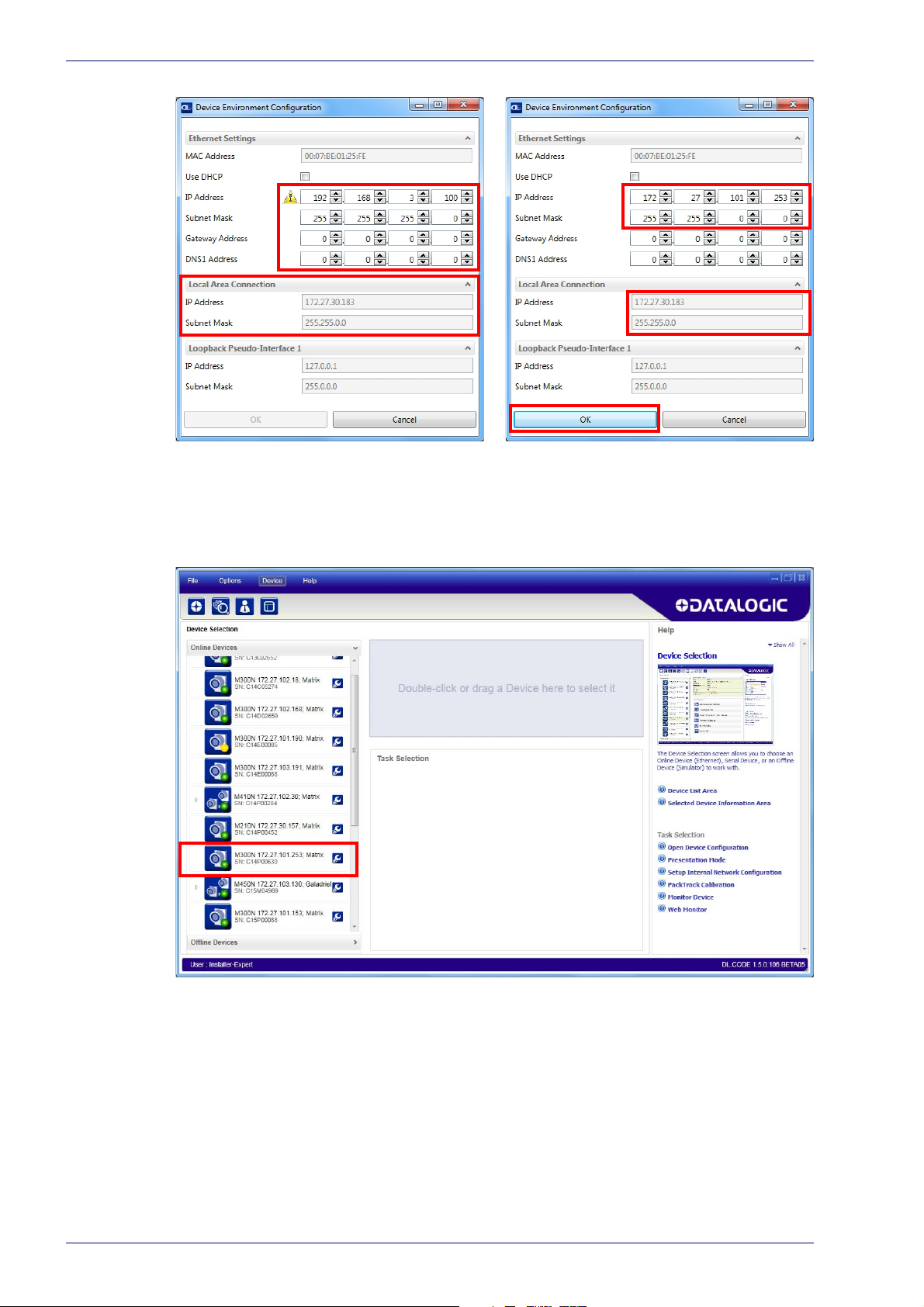
5. Change the Ethernet Settings (IP Address
etc.) according to the network requirements.
to open the Device Environment Configuration win-
, Subnet Mask, Gateway Address
its IP Address to the
Product Reference Guide 9
Page 26
Rapid Configuration
Figure 6 - Device Environment Configuration Window
6. Click OK; the device will reappear in the list of Online Devices (in color)
meaning it is now part of the LAN and can be configured. The new IP
address will also be displayed.
10
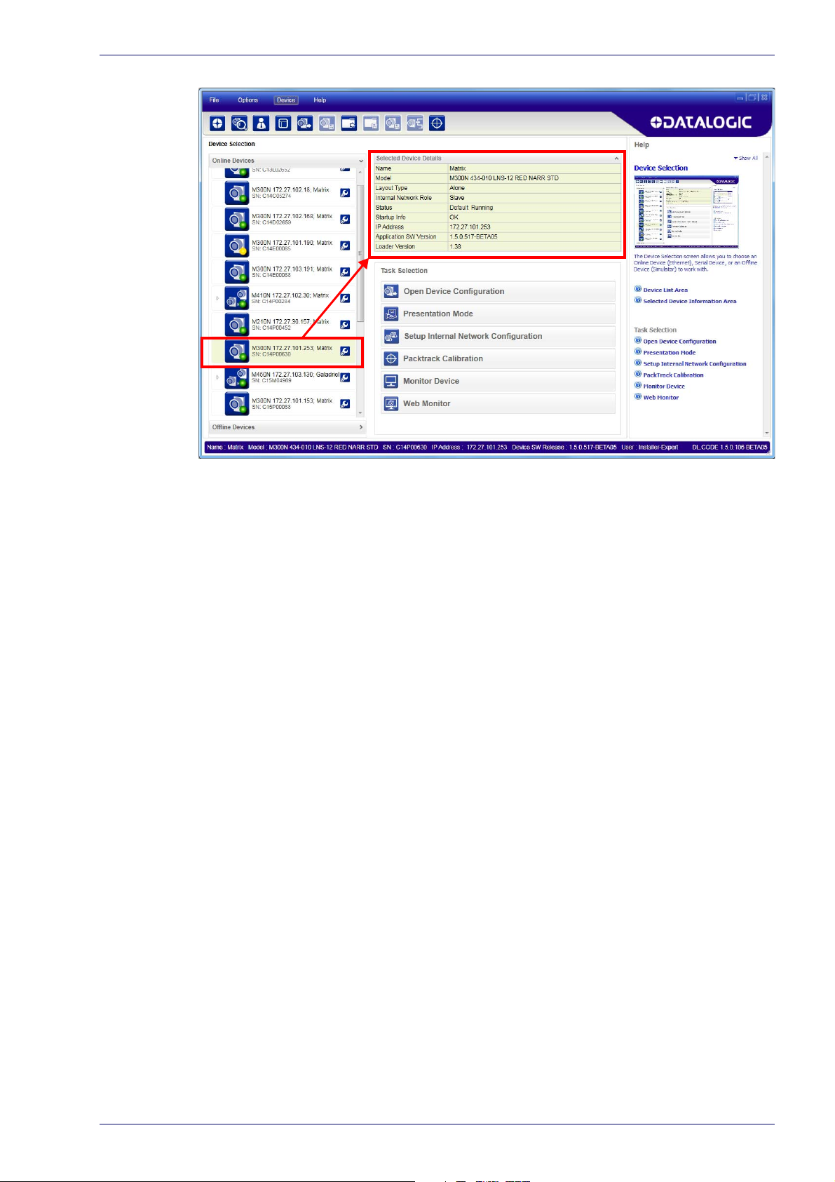
7. Double-click on or drag the device icon into the Selected Device Information Area. Details about the device will be displayed in this area.
Matrix 220
Page 27
Step 6 - Device Configuration
Figure 7 - DL.CODE Opening Window
Step 6 - Device Configuration
Automatic or Advanced Setup
Automatic Setup provides an automatic procedure for setting: optical/
illumination, reading distance, and code definition parameters to obtain the
most stable decoding conditions for a single code symbology based on the
images presented to the reader. It can be set to include Image Filters if
necessary. See the table below for codes and filters managed by Automatic
Setup. Automatic Setup is especially useful for DPM applications.
Product Reference Guide 11
Page 28

Rapid Configuration
Enabled 1D Codes Enabled 2D Codes Enabled Filters
CODE 128
EAN 128
CODE 39
CODE 93
CODABAR
PDF417
MICRO PDF417
GS1 DATABAR
GS1 DATABAR STACKED
GS1 DATABAR LIMITED
GS1 DATABAR EXPANDED
GS1 DATABAR EXPANDED STACKED
UPCEAN FAMILY EAN13
UPCEAN FAMILY EAN8
UPCEAN FAMILY UPCA
UPCEAN FAMILY UPCE
Advanced Setup provides access to the complete array of optical/illumination,
focusing adjustment, and code definition parameters that can be fine-tuned semiautomatically and manually to obtain the best results for applications of any
complexity.
DATAMATRIX ECC 200
QR
MICRO QR
AZTEC
MAXICODE
DOTCODE
ERODE 3x3, 5x5 and 7x7
DILATE 3x3, 5x5 and 7x7
SMOOTHING
NOTE
If your application requires multiple code symbologies, multiple image settings, Code
Grading or other parameter settings for decoding, then use the Advanced Setup, see
page15.
Automatic Setup
To begin configuration, the reader must be correctly mounted so that its Field of
View covers the application reading area.
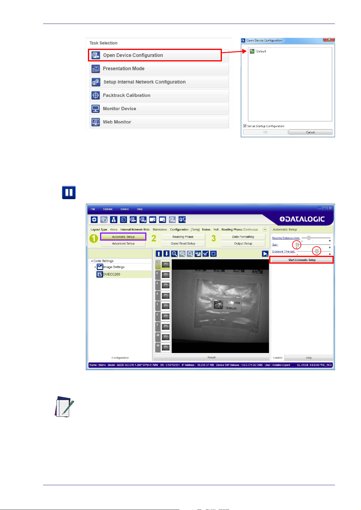
1. From the Task Area select Open Device Configuration.
2. The Open Device Configuration window opens showing the list of currently
ved configurations (jobs) saved on the device. For new devices, the only
sa
saved job is the Default configuration. Click OK. The device enters run
mode and begins acquiring images.
12
Matrix 220
Page 29
Step 6 - Device Configuration
3. Place the application code in front of the reader at the correct application
reading distance.
4. Click on the Pause button
to stop image acquisition.
If the image display area is too dark to see the images being captured, you can drag
the Gain and Exposure Time sliders (circled in red in the figure above) to the right to
increase visibility. This will not affect Automatic Setup.
NOTE
5. Click on the Start Automatic Setup button. The following window is displayed:
Product Reference Guide 13
Page 30
Rapid Configuration
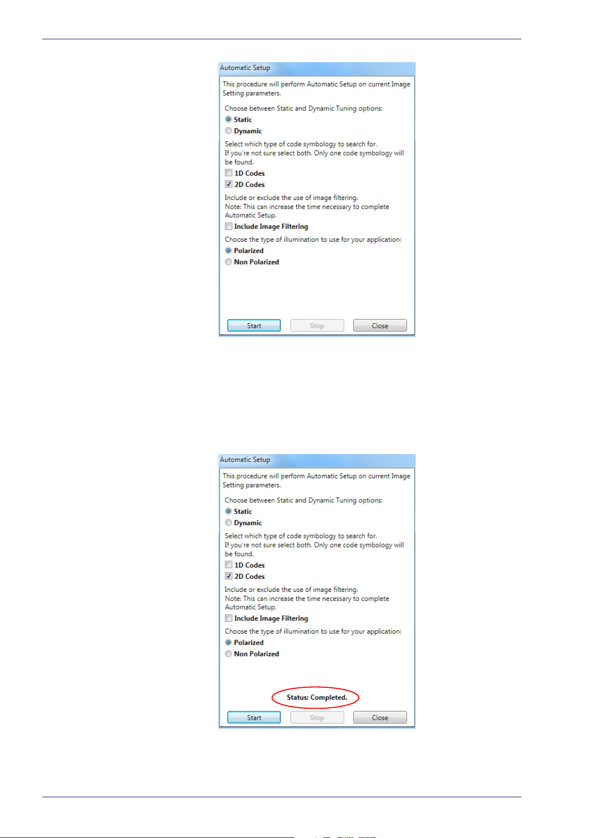
6. Select the correct reading conditions: Static or Dynamic Tuning, 1D or 2D
code, Include Image Filtering (to find the best decoding condition). For DPM
models you can select to use the Polarized or Non Polarized Illuminators.
7. Click Start to begin the procedure. The reader begins acquiring images. At
he end of the procedure the Status: Completed message appears. You can
t
Close the Automatic Setup window.
14
Matrix 220
Page 31

Step 6 - Device Configuration
Your reader is now optimized for decoding. Continue with the Reading Phase
configuration described on page 23.
Advanced Setup
To begin configuration, the reader must be correctly mounted at the correct
reading distance for your application so that its Field of View covers the
application reading area.
1. From the Task Area select Ope
2. The Open Device Configuration window opens showing the list of currently
d configurations (jobs) saved on the device. For new devices, the only
save
saved job is the Default configuration. Click OK. The device enters run
mode and begins acquiring images.
n Device Configuration.
Product Reference Guide 15
Page 32

Rapid Configuration
3. Click on the Advanced Setup button and press the Play icon.
4. Place the Gr
stop image acquisition by clicking on the Pause button
ade A Barcode Test Chart in the reading area. Once positioned,
.
16
5. Click the Image Settings branch and then click the Image Auto Setup button
to automatically acquire the best exposure time and gain values.
Matrix 220
Page 33

Step 6 - Device Configuration
6. Select the Static or Dynamic Self-Tuning option; Start Autolearn and Apply
to the Image Settings.
Product Reference Guide 17
Page 34

Rapid Configuration
After Applying the Image Auto-Setup you can see from the Image Settings
branch that the Exposure time and Gain parameters have been updated.
18
For applications having multiple lighting or code reading conditions, up to 10 different
Image Settings can be configured by adding them with the icon.
NOTE
7. Now select the General Image Settings branch and click on the Focus
Autolearn button.
Matrix 220
Page 35

The Reading Distance value
is not significant until the
Focus Autolearn procedure
ends successfully.
Step 6 - Device Configuration
8. The Calibrate dialog box opens allowing you to start the procedure. Click
Start.
Product Reference Guide 19
Page 36

Rapid Configuration
At the end of the calibration you can see the new Reading Distance and Image
Density (PPI) values as well as the FOV dimensions. Click Apply.
20
To enlarge the visual image of the code view, you can click on the zoom image icon
repositioning it on the code.
NOTE
Matrix 220
Page 37

NOTE
Step 6 - Device Configuration
At this point it is probably a good idea to save the configuration from temporary
memory to permanent memory giving it a specific name.
9. Now place an application specific code in front of the reader and repeat
only the Image Auto-Setup to register any changes in lighting or code surface contrast.
Product Reference Guide 21
Page 38

Rapid Configuration
10. Click on the Data Matrix ECC 200 symbology under the Image Settings
branch (enabled by default). If this symbology is among those in your application it will be shown in the image display with its code symbology name
d a small green box around it indicating it is decoded.
an
22
Matrix 220
Page 39

NOTE
Step 6 - Device Configuration
The large green box for each symbol indicates the code localization area which by
default is equal to the maximum FoV. It can be resized and moved by dragging its
borders with the mouse. The code must be found within this area in order to be
decoded.
11. Add your application specific codes to the Code Settings by selecting them
from the icons over the Configuration Parameters tree area. If the Data
Matrix symbology is not used, then delete it from the Code Settings with
the Delete icon
If you don’t know the code type, you can use the Code Autolearn feature by
icking on the Code Autolearn icon
cl
details.
12. For each code symbology set the relative parameters according to your
application.
.
.1 See the DL.CODE User’s Manual for
Reading Phase
1. Select your application specific Operating Mode from the icons over the
Configuration Parameters tree area: Continuous, One Shot or Phase Mode.
2. Configure the relative Operating Mode parameters from the Reading Phase
parameters panel. Different groups will appear in the panel depending on
the selected icons over the Configuration Parameters tree area.
1.
The Code Autolearn procedure will not recognize the following symbologies: Pharmacode, MSI,
Standard 2 of 5, Matrix 2 of 5.
Product Reference Guide 23
Page 40

Rapid Configuration
Good Read Setup
1. Select your specific data collection type from the icons over the Configuration Parameters tree area: Code Collection, Code Combination, Presentation
or Match
Modes; for example PackTrack Operating Mode only supports Code Combination. Incompatible data collection types will be shown in grey and cannot
be s
The following example shows Code Combination. By default, the Expected
des (when more than one code type is selected), are in logical AND,
Co
which means that all codes are required to be decoded to produce a Good
Read condition.
Code. Not all data collection types are available for all Operating
elected.
24
2. If a Good Read condition should be produced when any single code is
decoded, independent from the others, then they need to be combined in
logical XOR. To do this, drag the code icon(s) from their relative Expected
Code box into the Expected Code box of the XOR combination you wish to
create. Then delete the empty box by selecting it with the mouse (highlighted) and pressing the dele
te key on your keyboard.
Matrix 220
Page 41

Step 6 - Device Configuration
To create a logical AND condition from a logical XOR, create a new Expected
Code box using the Add icon
the other.
. Then drag the desired code icon from one box to
Data Formatting
1. Configure your application specific Data Formatting Message(s) from the
Configuration Parameters tree area: Message 1, Message 2, etc.
You can add fields to the output message by clicking on the icons above the
Message Field area. They will be appended to the message. You can drag them to
position them between other fields in the message so that the output message is
ordered according to your application requirements.
Each field has its own relative configuration parameters in the parameters panel.
Product Reference Guide 25
Page 42

Rapid Configuration
Output Setup
1. Configure your application specific Digital Output(s) and Green/Red Spots
(if used) from the Configuration Parameters tree area: Output 1, Output 2,
etc.
NOTE
Save the configuration from temporary memory to permanent memory, overwriting
the previously saved configuration.
26
Matrix 220
Page 43

Step 7 - Test Mode
≥ 20%
≥ 40%
≥ 60%
≥ 75%
≥ 95%
Use a code suitable to your application to test the reading performance of the
system.
1. Enter the
until the Test LED is on.
2. Release the button to enter the
Step 7 - Test Mode
Test
function by pressing and holding the X-PRESS push button
Test
function.
NOTE
Once entered, the Bar Graph on the five
starts reading codes the Bar-Graph shows the Good Read Rate.
3. To exit the Test, press the X-PRESS push button once.
By default, the Test exits automatically after three minutes.
LEDs is activated and if the reader
The Bar Graph has the following meaning:
In case of No Read condition, only the STATUS LED (red) is on and blinks.
Product Reference Guide 27
Page 44

Rapid Configuration
Advanced Reader Configuration
For further details on advanced product configuration, refer to the DL.CODE
User’s Guide available in the DL.CODE Help menu.
Host Mode Programming
The reader can also be partially configured from a host computer using the Host
Mode programming procedure.
28
Matrix 220
Page 45

Product Description
The Matrix 220 imager is the most compact image based barcode reader for top
performance with the highest flexibility. The ideal imager reader for Electronics,
Automotive, Packaging and Document Handling applications.
The Matrix 220 is designed for superior performance thanks to a 1.2 MPixel high
resolution sensor, a new platform and stronger decoding libraries.
The integrated powerful and flexible illumination system makes the Matrix 220
imager perfect for solving Direct Part Marking (DPM) code reading and quality
grade verification thanks to its innovative lighting solutions. The Matrix 220
offers in a single model the polarized and diffused light options resulting in
optimal illumination on any type of surface. The white, and red light models are
capable of solving a huge variety of applications with the best performance. The
electronic focus control allows easy remote job change during assembly line
reconfiguration with extreme reading flexibility.
Chapter 2
Introduction
In addition, the Continuous High-Power lighting mode can be selected which is
useful in Presentation Mode applications where the LED-array blinking
(produced by -Power Strobed lighting modes and rapidly occurring reading
phases) would otherwise disturb the operator.
Best ease of use thanks to the green and red spot lights, the X-Press™ button,
the intuitive HMI and the DL.CODE™ configuration software improved with the
Automatic Setup mode for a quick and easy code reading. ESD and YAG
protection are available as front cover accessories to enhance the product
flexibility reducing the number of models and simplifying the stock
management.
The IP67 and IP65 industrial grade, the operating temperature range from -10°C
to 50°C guarantee the best quality and robustness in the Manufacturing Industry
applications. The Matrix 220 imager offers cost-effective communication
options with Power over Ethernet (POE) connectivity and on-board PROFINET/IO
and ETHERNET/IP industrial fieldbus.
Product Reference Guide 29
Page 46

Introduction
Matrix 220 has been developed for use in numerous industries like:
Automotive
• DPM (Direct Part Marked) code validation after marking
• Work-in-progress control
• Assembly traceability
Electronics
• Track and trace PCB board manufacturing
• Electronic components
• Electronic products tracking
• DPM code reading (on plastic, glass, metal)
Packaging
• Primary packaging bar code reading
• Package traceability
• Food & beverage applications
Document Handling
• Fast decoding for high speed applications
This technology intrinsically provides omni-directional reading.
Standard Application Program
A Standard Application Program is factory-loaded onto Matrix 220. This
program controls code reading, data formatting, serial port and Ethernet
interfacing, and many other operating and control parameters. It is completely
user configurable from a Laptop or PC using the dedicated configuration
software program DL.CODE, provided on the DL.CODE mini-DVD
.zip file or mini-DVD accessory)
There are different programmable operating modes to suit various code reading
system requirements.
Quick, automatic focus, positioning, calibration and code setting of the imager
can be accomplished using the X-PRESS button and LEDs on top of the reader
without the necessity of a PC.
.
(downloaded
30
The previous functions can also be performed through DL.CODE which includes
visual feedback from the reader. This allows verification of the exact positioning
of the reader and to maximize its reading performance.
Statistics on the reading performance can also be visualized through a dedicated
window in DL.CODE.
Programmability
If your requirements are not met by the Standard Application Program, Custom
Application Programs can be requested at your local Datalogic distributor.
Some of the main features of this reader are given below:
Matrix 220
Page 47

Product Description
Excellent Performance
• 1.2 MPixels (960x1280)
• Electronic Adjustable Focus through software control
• Powerful Internal Lighting Systems
• Outstanding decoding capability on 1D, 2D, Stacked, Postal symbologies
• Excellent performance on DPM applications
• Omni-directional reading
• Frame Rate up to 45 frames/sec
• Image Cropping for higher frame rate
Ease of Setup
• Quick installation without PC by using X-PRESS interface for easy and intuitive setup
• LED pointers for aiming
• Automatic Imager calibration and Code Settings
• Visual Feedback to verify exact code positioning in the Field of View and to
maximize the reading performance
• Windows-based DL.CODE software to configure the reader parameters via
PC Ethernet interface
• User-defined database of Image Acquisition Settings (parameter sets)
Ease of Use
• X-PRESS interface LEDs provide operational and performance feedback
• Green Spot and beeper for immediate Good Read feedback
• Different operating modes to suit various application requirements
• Multi Image Acquisition Settings for higher reader flexibility
• Image saving and storage with buffering capability
• Diagnostic software tools
Flexible Solution
• Complete set of Accessories like mounting brackets, connection boxes,
cables and photocells
• Ethernet Connectivity with TCP/IP socket for reader parameter configuration, data and image transfer, FTP client, etc.
• On-board Ethernet supports EtherNet/IP, PROFINET I/O and Modbus TCP
protocols
• 3 serial communication interfaces (Main, Auxiliary, ID-NET)
• 2 General purpose optocoupled Inputs
• 3 General purpose optocoupled Outputs (when using the CBX connection
box)
Versatility
• Excellent reading performance on Direct Part Marked (DPM) symbols
• Code Quality Metrics reporting according to ISO/IEC 16022, ISO/IEC 18004,
ISO/IEC 15416 and AIM DPM standards for code quality trending.
• Match Code option with a user-defined match code database
Product Reference Guide 31
Page 48

Introduction
Industrial Strength
• Industrial compact 2D reader
• Rugged metal construction
• Sealed circular M12 connectors
• IP67 protection class
• 50 °C max operating temperature
• Supply voltage ranges from 10 to 30 Vdc
Indicator and Keypad Button
Figure 8 - Indicators
The following LED indicators are located on the reader:
PWR
NET
normal operating mode the colors and meaning of the five LEDs are illustrated
In
in the following table:
STATUS red LED indicates a NO READ result (Figure 8 -, 3)
COM
blue LED indicates that the reader is connected to the
power sup
yellow LED indicates connection to the on-board
hernet network (Figure 8 -, 2)
Et
yellow LED indicates active communication on the main
rial port * (Figure 8 -, 4)
se
ply (Figure 8 -, 1)
32
Matrix 220
Page 49

Indicator and Keypad Button
TRIGGER
GOOD green LED confirms successful reading (Figure 8 -, 6)
READY
* When connected to a Fieldbus network through the CBX500, the COM LED is
always active, even in the absence of data transmission, because of polling
activity on the Fieldbus network.
During the reader startup (reset or restart phase), these five LEDs blink for one
second.
In X-PRESS Configuration mode the colors and meaning of these five LEDs are
described in par.
The keypad button (Figure 8 -, 8), is software programmable. By default it starts
the X-PRESS interface for quick installation without using a PC (see "Step 4 - X-
PRESS Configuration" on page 6).
X-PRESS Human Machine Interface.
yellow LED indicates the status of the reading phase
Figure 8 -, 5)
(
green LED indicates that the reader is ready to
operate (
Figure 8 -, 7)
Product Reference Guide 33
Page 50

Introduction
Aiming LED Aiming LED
Red Spot
Green Spot
Aiming System
There are two red LED pointers that project two equidistant square patterns onto
the target area. The code should be centered between the two squares.
Figure 9 - Matrix 220 Aiming LEDs
LED Spots
There are two LED spots that can be activated to project light onto the target
area to give a visible indication that a particular event has occurred. The
associated event is configured through DL.CODE and is typically used to signal
Good Read/No Read events. The deactivation event can be signal driven or
managed by timeout.
Examples:
When associated with the Good Read event, the green spot illuminates the target
rea to indicate that decoding has occurred correctly according to the
a
configuration requirements.
When associated with the No Read event, the red spot illuminates the target area
to indicate
configuration requirements.(i.e. no code has been read).
that decoding has not occurred correctly according to the
34
Figure 10 - Matrix 220 Good Read/No Read LED Spots
Matrix 220
Page 51

ID-NET
ID-NET
The ID-NET network is a built-in high-speed interface dedicated for high-speed
reader interconnection. ID-NET is in addition to the Main and Auxiliary serial
interfaces.
The following network configurations are available:
• ID-NET Sy
nchronized: Single station – multiple readers
ID-NET interface allows local connection of multiple readers reading different
sides of the same target. All readers share a single presence sensor and activate/
deactivate simultaneously.
At the end of each reading phase a single data message is transmitted to the
. Thanks to ID-NET, data communication among readers is highly efficient
host
so that an immediate result will be available.
See "ID-N
Configurations" on page 122 for configuration details.
ET Interface" on page 60 for connection details and "Internal Network
Product Reference Guide 35
Page 52

Introduction
• ID-NET Multidata: Multiple stations – single reader
ID-NET interface allows connection of readers reading objects placed on
independent conveyors. All readers are typically located far away from each
other and they can have different operating modes from each other.
At the end of each reading phase, each reader
the host. Thanks to ID-NET, data collection among readers is accomplished at a
high speed without the need of an external multiplexing device. This leads to an
overall cost reduction and to simple system wiring.
D-NET Interface" on page 60 for connection details and "Internal Network
See "I
Configurations" on page 122 for configuration details.
X-PRESS Human Machine Interface
X-PRESS is the intuitive Human Machine Interface designed to improve ease of
installation and maintenance.
Status information is clearly presented b
whereas the single push button gives immediate access to the following relevant
functions:
transmits its own data message to
y means of the five colored LEDs,
36
• Test with bar graph visualization to check static reading performance
• Aim/Autofocus to turn on the LED poi
• Setup to perform Exposure Ti
• Learn to self-detect and auto-configure for reading unknown codes
me and Gain calibration
nters to aid positioning and focusing
Matrix 220
Page 53

X-PRESS Functions
Release button
Release button
to Exit
to enter Setup Mode to enter Learn Mode
Release button Release button
Release button Release button
to enter Aim/Autofocus Modeto enter Test Mode
(cycle)
to Exit
≥ 20%
≥ 40%
≥ 60%
≥ 75%
≥ 95%
Quick access to the following functions is provided by an easy procedure using
the push button:
X-PRESS Human Machine Interface
1. Press the
2. Ho
3. Release the
Once button is pressed, the cycle of LEDs activation is as follows:
ld the button until the specific function LED is on (Test, Aim, Setup or
Learn).
button (the Status LED will give a visual feedback).
button to enter the specific function.
Test Mode
Once entered, the Bar Graph on the five LEDs is activated and if the imager starts
reading codes the Bar-Graph shows the Good Read Rate. The Bar Graph has the
following meaning:
In case of a NO READ condition, only the Status LED (red) is on and blinks.
NOTE
To exit the Test Mode, press the X-PRESS
By default, the Test exits automatically after three minutes.
push button once.
Product Reference Guide 37
Page 54

Introduction
Focus/Aim
This function causes the LED indicators to turn on. The aiming pattern is
centered on the FOV vertically and horizontally. It can be used to position the
imager on the code. The Aim LED blinks to indicate this state.
You can exit the Focus/Aim function at any time by pressing the X-PRESS push
button once. After a short delay the aiming LED indicators turn off.
Setup
Once entered, the imager automatically performs Image Acquisition parameter
calibration for the specific code presented to it.
The Setup LED will blink until the procedure is completed.
The Setup procedure ends when the Image Acquisition parameters are
successfully saved in the reader memory, the Setup LED will stop blinking and
Matrix 220 emits 3 high pitched beeps.
If the calibration cannot be reached after a timeout of about 5 (five) seconds
Matrix 220 will exit without saving the parameters to memory, the Setup LED will
stop blinking and in this case Matrix 220 emits a long low pitched beep.
Learn
Once entered, the imager starts a procedure to automatically detect and
recognize a single code which is presented to it. Successive Learns will
substitute the current code.
The Learn LED will blink until the procedure is completed.
The Learn procedure ends when the Image Processing and Decoding parameters
are successfully saved in the reader memory, the Green Spot is activated, the
Learn LED will stop blinking and Matrix 220 emits 3 high pitched beeps.
If the autolearning cannot be reached after a timeout of about 3 (three) minutes,
Matrix 220 will exit without saving the parameters to memory, the Learn LED will
stop blinking and in this case Matrix 220 emits a long low pitched beep.
38
You can exit the Learn function at any time by pressing the X-PRESS push button
once. After a short delay the Learn procedure is cancelled.
Matrix 220
Page 55

Diagnostic Indication
MATRIX 220 3XX-0X0
Sensor
3 = 1.2 Mp
5 = standard white light 1 = standard 10-30 Vdc
0 = Standard
0 = 1D + 2D
4 = PoE 48 Vdc8 = DPM red multi-light
5 = 12 mm electronic focus
2 = 7 mm electronic focus
Optics
Internal Lighting System
Options
Input Power
Decoding
The “STATUS” (red) and “READY” LED (green) blink simultaneously to signal the
presence of an error. Diagnostic message transmission on interfaces can be
enabled to provide details about specific error conditions. See the Diagnostic
Error Conditions chart in the Diagnostic page of the DL.CODE Monitor.
Model Description
LED STATUS
Ready Blink
Good
Trigger
Com
Model Description
Matrix 220 readers are described by their model number which indicates the
characteristics listed in the diagram below. Not all combinations are available.
For a complete list of combinations see the Models tab on the Product page of
the website.
Status Blink
Product Reference Guide 39
Page 56

Introduction
Standard DPM
Diffused
Diffused
Polarized
Non-Polarized
Top
Bottom
Internal Lighting Systems
There are two different models of Internal Lighting Systems for Matrix 220
readers. The Standard Internal Lighting System is made up of 4 white light LEDs.
The DPM Internal Lighting System has a combination of three different types of
uminators which can be selected individually depending on the Direct Part
Ill
Mark application requirements.
Figure 11 - Matrix 220 Illuminators
Accessories
The following accessories can be used with the Matrix 220 reader.
Accessory Description Order No.
Cables
CAB-DS01-S M12-IP67 Cable To CBX or QL (1M) 93A050058
CAB-DS03-S M12-IP67 Cable To CBX or QL (3M) 93A050059
CAB-DS05-S M12-IP67 Cable To CBX or QL (5M) 93A050060
M12-IP67 GIGA Ethernet Cable X-Coded (1M) 93A050122
M12-IP67 GIGA Ethernet Cable X-Coded (3M) 93A050123
M12-IP67 GIGA Ethernet Cable X-Coded (5M) 93A050124
Adapter Cable GIGA Ethernet X-Coded M1
2 to RJ45 93A050128
Adapter Cable GIGA Ethernet X-Coded to Ethernet D-Coded 93A050129
CS-A1-03-U-03 PoE COM/Trigger Cable M12/5P Female to Free Wires (3M) 95ASE1170
CS-A1-03-U-05 PoE COM/Trigger Cable M12/5P Female to Free Wires (5M) 95ASE1180
CBL-1480-01 Thin M12/5P Male/Female (1M) 93A050049
CBL-1480-02 Thin M12/5P Male/Female (2M) 93A050050
CBL-1490 Term. Resist. Thin M12/5P/Male 93A050046
40
Matrix 220
Page 57

Accessories
Accessory Description Order No.
CBL-1496 Term. Resist. Thin M12/5P/Female 93A050047
Connectivity
CBX100 Compact Connection Box 93A301067
CBX500 Modular Connection Box 93A301068
BM100 Backup Module for CBX100/500 93ACC1808
BM150 Display Module for CBX500 93ACC1809
Various Fieldbus Host Interface Modules and All-In-One Connection Box Kits are available
BA100 DIN Rail Adapters 93ACC1821
BA200 Bosch and 80/20 Profile Adapters 93ACC1822
Various M12 Panel Connectors for CBX Connection Boxes are available
BA900 Two Cable Glands Panel 93ACC1847
QL100 Quick Link Slave ID-NET T-Connector 93ACC1860
QL150 Quick Link Slave ID-NET + Service T-Connector 93ACC1868
QL200 Quick Link Slave ID-NET + Power T-Connector 93ACC1861
QL300 Quick Link Master ID-NET - Serial Host Connector 93ACC1862
QLM500 Quick Link Metal Master ID-NET - EthernNet/IP Gateway 93ACC0037
QLM600 Quick Link Metal Master ID-NET - Profibus Gateway 93ACC0033
QLM700 Quick Link Metal Master ID-NET - Profinet I/O Gateway 93ACC0038
Various M12 Service Cables and Field Mount Connectors are available for Quick Link Series Connectors
Power Supplies
PG6002 AC/DC Power Supply Unit (US) 93ACC1718
PG6001 AC/DC Power Supply Unit (UK) 93ACC1719
PG6000 AC/DC Power Supply Unit (EU) 93ACC1720
Sensors
MEP-593 Photocell Kit PNP (PH-1) 93ACC1791
MEP-543 Photocell Kit-NPN 93ACC1728
S3Z-PR-5-C11-PL Diffuse Proximity Sensor 95B010011
Bracket
BK-22-000 Fixing Bracket M220 Body 93ACC0230
Covers
a
ESD ESD Safe Window Cover M220 93ACC0227
YAG YAG Cut Filter Window Cover M220 93ACC0228
ESD+YAG ESD Safe YAG Cut Filter Win Cover M220 93ACC0229
a. See note on IP Protection Class in Chapter 10.
Product Reference Guide 41
Page 58

Introduction
Application Examples
Document Handling
Matrix 220 is profitably used in the omnidirectional reading of 2D, stacked,
linear and postal codes for example in automated document handling and mail
processing systems.
Figure 12 - Address Coded in Data Matrix Symbology for Automated Mail Processing
Deformed or Overprinted Code Reading
Matrix 220 assures the reading of deformed and/or overprinted codes, even
though damaged or printed on high reflective surfaces.
Figure 13 - Unidose Flow-Pack with PDF417 Code
Figure 14 - Overprinted Barcode Readable by Matrix 220 also Through the Envelope Window
Film
42
Figure 15 - Barcode Printed on Curved Surface Readable by Matrix 300N in spite of Image
Optical Distortion
Matrix 220
Page 59

Direct Part Marking
Matrix 220 is also very powerful in reading low-contrast direct part marked
codes.
Figure 16 - Dot Matrix Code Directly Marked on Metal Surface by Using Dot Peening Technol-
Application Examples
ogy
Figure 17 - Dot Peening Marking on Metal Surface with Multi-dot per Code Element
Figure 18 - Directly Marked Dot Matrix Code Characterized by Outstanding Separation Dis-
Ink-Jet Printing Technology
tance between Adjacent Code Elements
Figure 19 - Dot Matrix Code Directly Marked on PCB Copper Pad by Using Ink-Jet Technology
Product Reference Guide 43
Page 60

Introduction
Laser Marking/Etching Technology
Figure 20 - Data Matrix Code Directly Marked on PCB Surface by Using Laser Etching Technol-
If application codes must be read which are produced by Laser Marking in real time,
use Matrix 220 models incorporating YAG Filters in order to avoid burning the CMOS
sensor.
CAUTION
ogy
44
Matrix 220
Page 61

Package Contents
Verify that the Matrix 220 reader and all the parts supplied with the equipment
are present and intact when opening the packaging; the list of parts includes:
• Matrix 220 reader (w/connector plug/cover)
• Quick Reference Guide
•Test Chart
•Mounting Kit
• Mounting Screws (2)
•Washers (2)
•Mounting Bracket
Chapter 3
Installation
Figure 21 - Package Contents
For Ethernet models the sealing connector plug provides IP67 protection when
Ethernet is not used. For PoE models the COM/Trigger connector cover provides
this protection when not used.
Product Reference Guide 45
Page 62

Installation
38
[1.50]
47
[1.85]
20.5
[0.81]
38
[1.50]
37.6
[1.48]
28.1
[1.11]
58
[2.27]
78
[3.07]
Ø3
[Ø0.12]
n°2
4 mm
x
mm
[inch]
optical axis
optical axis
Mechanical Dimensions
Matrix 220 can be installed to operate in different positions. The two screw holes
(M3 x 4mm depth) on the body of the reader are for mechanical fixture.
The diagrams below give the o
verall dimensions of the reader and may be used
for its installation.
Refer to page 51 for various mounting solutions
and correct positioning, and
Chapter 6 for FOV vs. Reading Distance considerations.
Figure 22 - Overall Dimensions Standard Models; Connector at 0°
46
Matrix 220
Page 63

n°2
4 mm
x
47
[1.85]
58
[2.30]
58
[2.26]
37.6
[1.48]
Ø3
[Ø0.12]
20.5
[0.81]
38
[1.50]
mm
[inch]
optical axis
optical axis
Mechanical Dimensions
Figure 23 - Overall Dimensions Standard Models; Connector at 90°
Product Reference Guide 47
Page 64

47
[1.85]
58
[2.27]
28.1
[1.11]
n°2
4 mm
37.6
[1.48]
20.5
[0.81]
78
[3.07]
43
[1.68]
43
[1.68]
x
Ø3
[Ø0.12]
mm
[inch]
optical axis
optical axis
Installation
Figure 24 - Overall Dimensions with Accessory Cover (ESD or YAG); Connector at 0°
48
Matrix 220
Page 65

47
[1.85]
63
[2.48]
37.6
[1.48]
58
[2.26]
20.5
[0.81]
n°2
4 mm
8
[0.32]
28.1
[1.11]
43
[1.68]
x
Ø3
[Ø0.12]
mm
[inch]
optical axis
optical axis
Mechanical Dimensions
Figure 25 - Overall Dimensions with Accessory Cover (ESD or YAG); Connector at 90°
Product Reference Guide 49
Page 66

65
[2.56]
2.5
[0.10]
3
.
5
[
0
.
1
4
]
20°
13
[0.51]
2.5
[0.10]
29.5
[1.16]
2
0
°
n°
4
90
°
mm
[inch]
Installation
Figure 26 - Mounting Bracket Overall Dimensions
50
Matrix 220
Page 67

Mounting And Positioning Matrix 220
Using the Matrix 220 mounting brackets you can obtain rotation on the various
axes of the reader as shown in the diagram below:
Mounting And Positioning Matrix 220
Figure 27 - Positioning with Mounting Bracket
Product Reference Guide 51
Page 68

Installation
No Pitch,
Tilt or Skew
Pitch
Minimize
Tilt
any angle
inside FOV
Skew
assure at least 10°
Matrix 220 is able to decode code labels at a variety of angles; however significant
angular distortion may degrade reading performance.
When mounting Matrix 220, take into consideration these ideal label position angles:
Pitch or Skew 10° to 20° and Tilt 0°.
Note: Since Matrix 220 is omni-directional on the code plane, the Pitch and Skew
angles have the same significance with respect to the code plane. However in some
advanced code reading applications performance can be improved by modifying the
Skew angle.
The Pitch, Skew and Tilt angles are represented in
Figure 28 -. Follow the
suggestions below for the best orientation:
Position the reader in order to avoid the direct reflection of the light emitted by the
Matrix 220 reader; it is advised to assure at least 10° for the Skew angle.
52
Figure 28 - Code Reading Orientation
In some cases, such as low contrast or low illumination, it can be useful to use a
Pitch or Skew angle = 0°.
The Til
t angle is also represented in Figure 29 -. Matrix 220 can read labels with
any tilt angle. Keep in mind however, that since linear barcodes are rectangular,
the reade
r should be aligned to fit them into the horizontal FOV.
Matrix 220
Page 69

Mounting And Positioning Matrix 220
Figure 29 - Tilt Angle Considerations
See Chapter 6 for FOV vs. Reading Distance considerations.
Product Reference Guide 53
Page 70

Installation
Mounting Accessory Covers
To mount the Accessory ESD or YAG Cut filter covers, follow the instructions
bellow.
NOTE
Figure 30 - Accessory Cover Mounting
1. Remove the cover plates and screws.
2. Make sure the window is clean of any dirt, dust or fingerprints. If necessary
wipe it with a clean tissue.
3. Place the cover over the Matrix 220 reader and press down on the cover
rame edges until the screw holes align.
f
To avoid damage, do not press on the window.
4. Insert one of the screws; to avoid damage to the threads, turn it counterc
lockwise a couple of turns until it aligns properly. Then turn it clockwise
several turns until partially tightened.
5. Repeat step 3 and 4 for the second screw.
6. Tighten both screws to 25 cN m of torque.
The ESD accessory covers are supplied with an adhesive label that can be
applied onto the reader indicating that the reader is now ESD safe.
54
Matrix 220
Page 71

NOTE
Chapter 4
Electrical Connections
All Matrix 220 Standard Input Power models can be connected to a CBX
connection box through one of the available CAB-DSxx-S accessory cables.
These accessory cables terminate in an M12 17-pin connector on the Matrix 220
side and in a 25-pin male D-sub connector on the CBX side.
All Matrix 220 Power over Ethernet (PoE) models have an additional COM and Trigger
connector which can be connected through custom cables. See
wiring details.
We recommend making system connections through one of the CBX connection
boxes since they offer the advantages of easy connection, easy device
replacement, opto-isolated outputs (Outputs 1 and 2), and filtered reference
signals.
Appendix A for direct
If you require direct wiring to the reader the connections are the same as shown in
this chapte
cated in
NOTE
r with the exception of the digital Outputs. Direct wiring details are indi-
Appendix A.
CBX Connection Box Pinout
The table below gives the pinout of the CBX100/500 terminal block connectors.
Use this pinout when the Matrix 220 reader is connected by means of the
CBX100/500:
Group Label Description
Input Power Vdc Power Supply Input Voltage +
GND Power Supply Input Voltage -
Earth Protection Earth Ground
Inputs +V Power Source - External Trigger
I1A External Trigger A (polarity insensitive)
I1B External Trigger B (polarity insensitive)
-V Power Reference - External Trigger
Product Reference Guide 55
Page 72

Electrical Connections
Inputs +V Power Source - Inputs
Outputs +V Power Source - Outputs
Group Label Description
I2A Input 2 A (polarity insensitive)
I2B Input 2 B (polarity insensitive)
-V Power Reference - Inputs
-V Power Reference - Outputs
O1+ Output 1 + opto-isolated and polarity sensitive
O1- Output 1 - opto-isolated and polarity sensitive
O2+ Output 2 + opto-isolated and polarity sensitive
O2- Output 2 - opto-isolated and polarity sensitive
O3A
Auxiliary Interface TX Transmit Data
RX Receive Data
SGND Auxiliary Interface Signal Ground
ID-NET REF Network Reference
ID+ ID-NET network data +
ID- ID-NET network data -
Shield Network Cable Shield
Main Interface RS232 RS422 Full Duplex
TX TX+
RX *RX+
- TX-
- *RX-
SGND SGND
Output 3 - opto-isolated (only available through
BX500)
C
56
* Do not leave floating, see "RS422 Full Duplex Interface" on page 59 for connection
details.
To avoid electromagnetic interference when the reader is connected to a CBX connection box, verify the jumper positions in the CBX as indicated in its Installation Manual.
NOTE
Matrix 220
Page 73

Power Supply
Power Supply
Earth
Ground
V+ in
VGND
Power requirements and conditions depend on the Matrix 220 model: Standard
or PoE (Power over Ethernet).
Standard Models
For these models power can be supplied to the reader through the CBX100/500
spring clamp terminal pins as shown in Figure 31 -:
Power Supply
Figure 31 - Power Supply Connections
The power must be between 10 and 30 Vdc only.
It is recommended to connect the device CHASSIS to earth ground (Earth) by
set
ting the appropriate jumper in the CBX connection box. See the CBX
Installation Manual for details.
Power Over Ethernet (PoE) Models
The Ethernet pinout is as follows:
Pin Name Description
1 TX+ Transmit data +
2 TX- Transmit data -
3 RX+ Receive data +
4 RX- Receive data -
5 DC1- DC power (-)
6 DC2- DC power (-)
7 DC1+ DC power (+)
8 DC2+ DC power (+)
Power can be applied to any of th
standard for Alternative A (Mid and Endspan) or Alternative B.
e data pairs according to the IEEE 802.3af
Figure 32 - M12 X-Coded Female
Ethernet Network Connector
Product Reference Guide 57
Page 74

Electrical Connections
User Interface
Reader
RXTXSGND
TXDRXDSGND
Main Serial Interface
Do not connect to the Main Interface spring clamp terminals if using Host Interface
Modules (Fieldbus) with the CBX500.
CAUTION
The signals relative to the following serial interface types are available on the
CBX spring clamp terminal blocks.
The main serial interface type and its param
be defined by the user via DL.CODE software. For more details refer to the Help
On Line page of the Reading Phase step (Channels) in DL.CODE.
Details regarding the connections and use of the interfaces are given in the next
raphs.
parag
RS232 Interface
The RS232 interface is generally used for Point-to-Point connections. When it is
connected to the host computer it allows transmission of code data.
The following pins are used for RS232 interface connection:
eters (baud rate, data bits, etc.) can
CBX100/500 Description
TX Transmit Data
RX Receive Data
58
SGND Signal Ground
It is always advisable to use shielded cables. The overall maximum cable length
must
be less than 15 m (49.2 ft).
Figure 33 - RS232 Main Interface Connections
Matrix 220
Page 75

RS422 Full Duplex Interface
User Interface
SGND
Reader
RX422- TX422-
TX422+
RX422+
TX- RX-
RX+
TX+SGND
User Interface
SGND
Reader
RX422-
RX422+
SGND TX+
TX-
The RS422 full-duplex (5 wires + shield) interface is used for non-polled
communication protocols in point-to-point connections over longer distances
(max 1200 m / 3940 ft) than those acceptable for RS232 communications or in
electrically noisy environments.
The CBX pinout follows:
CBX100/500 Description
TX+ RS422 Transmit Data +
RX+ RS422 Receive Data +
TX- RS422 Transmit Data -
RX- RS422 Receive Data -
SGND Signal Ground
Main Serial Interface
NOTE
Figure 34 - RS422 Full Duplex Connections
For applications that do not use RS422 transmission to the reader (terminal block RX+
and RX- signals), do not leave these lines floating but connect them to SGND as
shown below.
Figure 35 - RS422 Full Duplex Connections Using Only TX Signals to Host
Product Reference Guide 59
Page 76

Electrical Connections
ID-NET Interface
ID-NET Cables
The following instructions are referred to Figure 37 -, Figure 38 - and Figure 39
-.
CBX100/500 Description
Shield Network Cable Shield
ID+ ID-NET Network Data +
ID- ID-NET Network Data -
REF Network Reference
• The general cable type specifications ar
CAT5 twisted pair, shielded cable AWG 24 (or AWG 22) stranded flexible.
We recommend using DeviceNet cables (drop or trunk type) to the following
reference standards:
AN50325 – IEC 62026
UL STYLE 2502 80°C 30V
• Cable Shield MUST be connected to earth ground ONLY at the Master.
• NEVER use ID-NET cable shield as common reference.
• The ID-NET max cable length depends on
drate Table below).
• For Common Power Connections use only 2 wires (ID+ and ID-).
• DC Voltage Power cable (Vdc – GND) should
(i.e. do not put it together with AC cable):
• Wire dimensioning must be checked in
greater than 0.8 Volts.
• Cable should lie down as near as possible to the ID-NET cable (avoiding
loops between them).
wide
• Reader's chassis may be connected to earth.
e: CAT5 twisted pair + additional
the baudrate used, (see the Bau-
be handled as a signal cable
order to avoid voltage drops
60
• Network inside the same building.
Baudrate Table
Baudrate 125 kbps 250 kbps 500 kbps 1 Mbps
Cable Length 1200 m 900 m 700 m *
* Application depe
ndent, contact your Datalogic representative for details.
Matrix 220
Page 77

The default ID-NET baudrate is 500 kbps. Lower ID-NET baudrates allow longer cable
lengths.
NOTE
ID-NET Response Time
The following figure shows the response time of the ID-NET network. This time
is defined as the period between the Trigger activation and the beginning of data
transmission to the Host.
ID-NET Interface
Figure 36 - ID-NET Response Time
Conditions
• ID-NET M/S Synchronized layout
• message length = 50 bytes per node
Product Reference Guide 61
Page 78

Electrical Connections
ID-NET Network Termination
The network must be properly terminated in the first and last reader of the
network. This is done by setting the ID-NET Termination Resistance Switch in the
CBX100/500 to ON.
ID-NET Connection Diagrams
62
Figure 37 - ID-NET Network Connections with isolated power blocks
Matrix 220
Page 79

ID-NET Interface
Figure 38 - ID-NET Network Connections with Common Power Branch Network
Product Reference Guide 63
Page 80

Electrical Connections
64
Figure 39 - ID-NET Network Connections with Common Power Star Network
Matrix 220
Page 81

Auxiliary RS232 Interface
15
69
User Interface
RX TX
Reference
The RS232 auxiliary interface is available for Point-to-Point connections. When it
is connected to the host computer it allows transmission of code data.
The parameters relative to the aux interface (baud rate, data bits, etc.) can be
fined through the Reading Phase step (Channels) in DL.CODE.
de
The 9-pin female Auxiliary Interface connector inside the CBX is the preferred
nnector for temporary communication monitoring.
co
Auxiliary RS232 Interface
Figure 40 - 9-pin female connector
If permanent system wiring is required, the following pins are used to connect
the RS232 auxiliary interface:
CBX100/500 Description
TX Auxiliary Interface Transmit Data
RX Auxiliary Interface Receive Data
SGND Auxiliary Interface Reference
Do not connect the Aux Interface to the CBX spring clamp connectors and the 9-pin
connector simultaneously.
NOTE
Product Reference Guide 65
Page 82

Electrical Connections
Inputs
There are two optocoupled polarity insensitive inputs available on the reader:
Input 1 (External Trigger) and Input 2, a generic input:
The External Trigger can be used in One Shot Mode or in Phase Mode. Its main
nctions are:
fu
• acquisition trigger in One Shot Mode
• reading phase-ON/reading phase-OFF
The main functions of the general purpose Input 2 are:
• second external trigger in Phase Mode
• match code storage command when the Match Code option is enabled
The electrical features of both inputs are:
V
I
= 30 Vdc max.
AB
= 10 mA (reader) + 12 mA (CBX) max.
IN
command in Phase Mode
NOTE
The active state of these inputs are selected in software.
An anti-disturbance filter, by default, is implemented in software on both inputs.
Th
e value can be changed through the software parameter Debounce Filter. See
the Help On Line page of the Reading Phase step (Inputs) in DL.CODE for further
details on these parameters.
These inputs are optocoupled and can be d
commands.
riven by both NPN and PNP type
Polarity insensitive inputs assure full functionality even if pins A and B are
exchanged.
The connections are indicated in the following diagrams:
CBX100/500 Description
66
+V Power Source - External Trigger
I1A External Trigger A (polarity insensitive)
I1B External Trigger B (polarity insensitive)
-V Power Reference - External Trigger
The yellow Trigger LED (Figure 8 -, 5) is on when the active state of the External
Trigger corresponds to ON.
Matrix 220
Page 83

External Trigger Input Connections Using Matrix 220 Power
Power from the Vdc/GND spring clamps is available directly to the Input Device on
the +V/-V spring clamps, and does not pass through the Power Switch (ON/OFF)
inside the CBX. Disconnect the power supply when working inside the CBX.
CAUTION
Inputs
Figure 41 - PNP External Trigger Using Matrix 220 Power
Product Reference Guide 67
Page 84

Electrical Connections
Figure 42 - NPN External Trigger Using Matrix 220 Power
68
Matrix 220
Page 85

External Trigger Input Connections Using External Power
PNP Photocell
Input
Signal
Pulled down to External
Input Device Reference
NPN Photocell
Input
Signal
Pulled up to External
Input Device Power
Figure 43 - PNP External Trigger Using External Power
Inputs
Figure 44 - NPN External Trigger Using External Power
CBX100/500 Description
+V Power Source - External Trigger
I2A Input 2 A (polarity insensitive)
I2B Input 2 B (polarity insensitive)
-V Power Reference - External Trigger
Input 2 Connections Using Matrix 220 Power
Power from the Vdc/GND spring clamps is available directly to the Input Device on
the +V/-V spring clamps, and does not pass through the Power Switch (ON/OFF)
inside the CBX. Disconnect the power supply when working inside the CBX.
CAUTION
Product Reference Guide 69
Page 86

Input Device
Power to
Input Device
Input Device
Reference
Input
Signal
Electrical Connections
Input Device
Power to
Input Device
Input Device
Reference
Input
Signal
Pulled down to External
Input Device Reference
Input Device
Input
Signal
Input Device
Input
Signal
Pulled up to External
Input Device Power
Figure 45 - PNP Input 2 Using Matrix 220 Power
Figure 46 - NPN Input 2 Using Matrix 220 Power
Input 2 Connections Using External Power
Figure 47 - PNP Input 2 Using External Power
70
Figure 48 - NPN Input 2 Using External Power
Matrix 220
Page 87

Input 3 Connections (CBX500 Only)
RESERVED
Figure 49 - Input 3 Using External Power
Do not connect to I3A or I34B signals, they are reserved.
CAUTION
Outputs
Outputs
CAUTION
When Outputs 1 and 2 are connected through the CBX connection box, they become
opto-isolated and polarity sensitive and acquire the electrical characteristics listed
below. To function correctly, they require setting the Output Line Type configuration
parameters to NPN for the respective output. The hardware connection to the CBX
can be either NPN or PNP.
Three general purpose outputs are available and their meaning can be defined
by the user. They are typically used either to signal the data collection result or
to control an external lighting system.
CBX100/500 Description
+V Power Source - Outputs
O1+ Output 1 + opto-isolated a
O1- Output 1 - opto-isolated and polarity sensitive
O2+ Output 2 + opto-isolated a
nd polarity sensitive
nd polarity sensitive
O2- Output 2 - opto-isolated and polarity sensitive
O3A Output 3 non opto-isolated (only available on CBX500)
-V Power Reference - Outputs
The electrical features of the outputs are the following:
Product Reference Guide 71
Page 88

Electrical Connections
Output 2 Device
Power to
Output Device
Output Device
Reference
Output
Signal
Output 1 Device
Power to
Output Device
Output
Device
Reference
Output
Signal
Outputs 1 and 2 Output 3
VCE = 30 Vdc max.
ICE = 40 mA continuous max.; 130 mA
pulsed max.
V
CE saturation
P
= 90 mW Max. @ 50 °C ambient temp. I
D
= 1 Vdc max. @ 10 mA V
Reverse-Polarity and Short-Circuit Protected
V
(I
OUT
OUT
LOAD
= 0 mA) max = 30 Vdc
LOAD
(I
= 100 mA) max = 3 Vdc
LOAD
max = 100 mA
By default, Output 1 is associated with the No Read event, which activates when
the code(s) signaled by the external trigger are not decoded, and Output 2 is
associated with the Good Read event, which activates when all the selected codes
are correctly decoded.
The output signals are fully programmable being determined by the configured
ctivation/Deactivation events, Deactivation Timeout or a combination of the
A
two. Refer to the DL.CODE parameters Help On Line for further details.
Output 1 and 2 Connections Using Matrix 220 Power
Power from the Vdc/GND spring clamps is available directly to the Output Device on
the +V/-V spring clamps, and does not pass through the Power Switch (ON/OFF)
inside the CBX. Disconnect the power supply when working inside the CBX.
CAUTION
Figure 50 - PNP/Open Emitter Output Using Matrix 220 Power
72
Matrix 220
Page 89

Output 2 Device
Power to
Output Device
Output Device
Reference
Output
Signal
Output 1 Device
Power to
Output Device
Output Device
Reference
Output Signal
Figure 51 - NPN/Open Collector Output Using Matrix 220 Power
Output 2 Device
Output
Signal
Output 1 Device
Output
Signal
Pulled up to External
Output Device Power
Pulled up to External
Output Device Power
Pulled down to External
Output Device Reference
Output 2 Device
Output
Signal
Output 1 Device
Output
Signal
Pulled down to External
Output Device Reference
Output 1 and 2 Connections Using External Power
Outputs
Figure 52 - PNP/Open Emitter Output Using External Power
Figure 53 - NPN/Open Collector Output Using External Power
Output 3 is not opto-isolated but can be assigned to the same events. By default
it is not assigned to any event. The CBX500 must be used to connect this output.
For this output, set the Line Type configuration parameter according to the hardware
connection to the CBX: NPN, PNP or Push-Pull.
NOTE
Product Reference Guide 73
Page 90

Electrical Connections
Power to
Output Device
Output Device
Reference
Output
Signal
Output 3 Device
Output Device
Reference
Output
Signal
Output 3 Device
Output 3 Connections Using Matrix 220 Power (CBX500 Only)
Figure 54 - Output 3 Using Matrix 220 Power
Output 3 Connections Using External Power (CBX500 Only)
CAUTION
Figure 55 - Output 3 Using External Power
Do not connect to I3A or I34B signals, they are reserved.
74
Matrix 220
Page 91

On-Board Ethernet Interface
The on-board Ethernet Interface can be used for TCP/IP communication with a
remote or local host computer by connecting the reader to either a LAN or
directly to a host PC. There is no need to use a crossover adapter since Matrix
220 incorporates an auto-cross function.
On-Board Ethernet Interface
A CAB-ETH-M0x c
On the Matrix 220 on-board Ethernet interface the following communication
hannels are available:
c
• TCP Client
•TCP Server
•UDP Channel
•FTP Client
The following Fieldbus protocols are also available over the on-board Ethernet
in
terface:
• EtherNet/IP
• PROFINET IO
• Modbus TCP Client
For further details refer to the Help On Line page of the Reading Phase step
nnels) and (Fieldbuses) in DL.CODE.
(Cha
able can be used to connect to a LAN.
User Interface - Serial Host
The following table contains the pinout for standard RS232 PC Host interface.
For other user interface types please refer to their own manual.
9-pin male connector 25-pin male connector
Pin Name Pin Name
2 RX 3 RX
3 TX 2 TX
5 GND 7 GND
RS232 PC-side Connections
Product Reference Guide 75
Page 92

NOTE
Chapter 5
Typical Layouts
The following typical layouts refer to system hardware configurations. However,
they also require the correct setup of the software configuration parameters.
Dotted lines in the figures refer to optional hardware configurations within the
particular layout.
All software configurations are made through DL.CODE which connects to the reader
through the on-board Ethernet interface.
NOTE
NOTE
DL.CODE now supports several different multi devi
PASS-THROUGH configuration. In particular this feature allows MULTIDATA ID-NET
network configurations to be made. Master/Slave SYNCHRONIZED ID-NET network
configurations are also configurable as before.
The Master/Slave Role is only significant for the Internal ID-NET N
out doesn’t use the ID-NET network then the device’s Role is not significant and can
be ignored.
ce configuration types using the
etwork. If your lay-
76
Matrix 220
Page 93

Ethernet Connection
PG6000
Host
CAB-DSxx-S
Matrix 220
CAB-ETH-M0x
CBX
Ethernet Interface
Auxiliary Serial Interface (RS232 - Data Monitor)
External Trigger (for One Shot or Phase Mode)
Alone
The Ethernet connection is possible in two different layouts.
In a Point-to-Point layout the reader is connected to a local host by using a CABET
H-M0x cable. There is no need to use a crossover adapter since Matrix 220
incorporates an autocross function.
Ethernet Connection
Figure 56 - Ethernet Point-to-Point Layout
All devices always support multiple output channels (i.e. for data monitoring).
Product Reference Guide 77
Page 94

Typical Layouts
Host
CAB-DSxx-S
Matrix 220
CAB-ETH-M0x
Ethernet Interface
Auxiliary Serial Interface (RS232 - Data Monitor)
External Trigger (for One Shot or Phase Mode)
Alone
Alone Alone
CBX
CBX
Switch
Power
Host
Matrix 220
CAB-ETH-M0x
Alone Alone Alone
PoE Switch
When using a Local Area Network (LAN), one or more Matrix 220 readers can be
connected to the network by using CAB-ETH-M0x cables:
Figure 57 - Ethernet Network Layout
Figure 58 - PoE Ethernet Network Layout
78
Matrix 220
Page 95

Serial Connection
PG6000
Host
CAB-DSxx-S
CBX
Main Serial Interface (RS232 or RS422 Full-Duplex)
Auxiliary Serial Interface (RS232 - Data Monitor)
External Trigger (for One Shot or Phase Mode)
Alone
In this layout the data is transmitted to the Host on the main serial interface. The
Ethernet interface can be used for reader configuration by connecting a laptop
computer running DL.CODE.
Serial Connection
Data can be transmitted on the RS232 aux
iliary interface independently from the
main interface selection to monitor data.
When One Shot or Phase Mode operating mode is used, the reader can be activated by an External Trigger (for exampl
e a pulse from a photoelectric sensor)
when the object enters its reading zone.
Figure 59 - Serial Interface Point-to-Point Layout
All devices always support multiple output channels (i.e. for data monitoring).
Product Reference Guide 79
Page 96

Typical Layouts
Host
CAB-DSxx-S
Matrix 220
CBX500
Fieldbus Interface (Profibus, DeviceNet, etc.)
Auxiliary Serial Interface (RS232 - Data Monitor)
External Trigger (for One Shot or Phase Mode)
Alone
Power
Fieldbus Connection
In this layout a single reader functions as a Slave node on a Fieldbus network.
The data is transmitted to the Host through an accessory Fieldbus interface
board installed inside the CBX500 connection box.
Reader configuration can be accomplished th
rough the Ethernet interface using
the DL.CODE configuration program.
Data can be transmitted on the RS232 auxiliary interface independently from the
ieldbus interface selection to monitor data.
F
When One Shot or Phase Mode operating mode is used, the reader can be activated by an External Trigger (photoelectric sensor) when the object enters its
re
ading zone.
80
Figure 60 - Fieldbus Interface Point-to-Point Layout
All devices always support multiple output channels (i.e. for data monitoring).
Matrix 220
Page 97

Pass-Through
Host
CAB-DSxx-S
Phase
CAB-ETH-M0x
Ethernet TCP/IP Server 1
Ethernet TCP/IP Server 2
Main Serial Interface (RS232 or RS422 Full-Duplex)
Auxiliary Serial Interface (RS232)
Pass-through Input Channel
Output Channel
Alone
Alone Alone
CBX
Switch
Power
Mode
Continuous
Mode
External
Trigger
The pass-through layout allows each device working Alone, to collect data from
one or more pass-through input channels and send this data plus its own on one
or more different
Pass-Through
output channels.
In this way independent devices can be co
nnected together in combinations to
create multi device networks. Many devices reading independently can send their
messages through a common output channel which instead of being directed at
a Host can be collected by another device on its pass-through input channel and
sent to a Host on a different output channel.
In a Pass-through layout each device supports multiple pass-through configurations to accept input from different devices on different channels (i.e. middle
reader above). However, readers are not required to have a pass-through configuration if they don’t need to receive data from an input channel (i.e. right reader
bove). The overall data collection device always has at least one pass-through
a
configuration to collect the input data from the other devices and send it to the
Host (i.e. left reader above).
All devices always support multiple output
Product Reference Guide 81
In a Pass-through layout each device can have a different operating mode: Continuous, One Shot, Phase Mode, etc.
Figure 61 - Pass-Through Layout
channels (i.e. for data monitoring).
Page 98

Typical Layouts
Host
CAB-DSxx-S
Phase
CAB-ETH-M0x
Ethernet TCP/IP Server 1
ID-NET (up to 32 devices, max network extension of 1000 m)
Main Serial Interface (RS232 or RS422 Full-Duplex)
Auxiliary Serial Interface (RS232)
Pass-through Input Channel
Output Channel
Alone
Alone Alone
CBX
Switch
Power
Mode
Continuous
Mode
External
Trigger
ID-NET
Master
ID-NET
Slave#1
ID-NET
Slave#2
ID-NET Multidata Network (Pass-Through)
A special case of the pass-through layout allows each Slave device working
Alone, to collect data from one or more pass-through
this data plus its own on the ID-NET
The Slave readers are connected together using the ID-NET interface. Every Slave
ader must have an ID-NET address in the range 1-31.
re
output channel to the Master.
input channels and send
The Master collects the data from its
pass-through ID-NET input channel and
sends it to the Host on a different output channel.
In a Pass-through layout each device supports multiple pass-through configurations to accept input from different devices on different channels (i.e. Master
reader above). However, ID-NET Slave readers are not required to have a passthrough configuration if they don’t need to receive data from an input channel
(i.e. right reader above). The ID-NET Master always has at least one pass-through
configuration to collect the ID-NET Slaves data and send it to the Host.
82
Slave devices cannot receive data from a pass-through ID-NET input channel and
Master devices cannot send data on an ID-NET output channel.
NOTE
Figure 62 - ID-NET Multidata Layout (Pass-through)
Matrix 220
Page 99

All devices always support multiple output channels (i.e. for data monitoring).
Host
Power
ID-NET
Master
Synchronized
ID-NET
Slave#1
Synchronized
ID-NET
Slave#n
Synchronized
Main Serial Interface (RS232 or RS422 Full-Duplex)
External Trigger
ID-NET (up to 16 devices - practical limit)
In a Pass-through layout each device can have a different operating mode: Continuous, One Shot, Phase Mode, etc.
ID-NET Synchronized Network
When the device is working Synchronized, the ID-NET connection is used to collect data from several readers to build a
system; there can be one Master and up to 31 Slaves connected together.
ID-NET Synchronized Network
multi-point or a multi-sided reading
The Slave readers are connected together usi
ng the ID-NET interface. Every slave
reader must have an ID-NET address in the range 1-31.
The Master reader is also connected to the Host on one of its communication
annels. In the following examples the RS232/RS422 main serial interface is
ch
used.
For a Master/Slave Synchronized layout the External Trigger signal is unique to
th
e system; there is a single reading phase and a single message from the Mas-
ter reader to the Host computer. It
is not necessary to bring the External Trigger
signal to all the readers.
In the Master/Slave Synchron
set to
PackTrack or Phase Mode.
ized layout the Master operating mode can only be
The Main and ID-NET interfaces are connected as shown in the following figures.
Product Reference Guide 83
Figure 63 - ID-NET Synchronized Layout
Page 100

Typical Layouts
Host
Power
CAB-PW-EXT
CBX500
CAB-AUX03
CBL-1480-xxID-NET
Q100
ID-NET Synchronized Slave Nodes
ID-NET
Synchronized
Master
CAB-DSxx-S
PS
CBL-1490
Q100
ID-NET
Terminator
CBL-1480-xx
The ID-NET network must be terminated
through the internal switch of the CBX500
and inserting an ID-NET terminator into
the last QL in the network.
Main
BA600 ID-NET Out
BA400 Ext. Power
BA500 Trigger
BA300 Service
Host
Power
CAB-PW-EXT
CBL-1480-xx
QL300
Q100
ID-NET Synchronized Slave Nodes
ID-NET
Synchronized
Master
PS
CBL-1490
Q100
ID-NET
Terminator
CBL-1480-xx
The ID-NET network must be terminated inserting an ID-NET terminator
into the QL300 (Master) and into the
last QL in the network.
Main Interface
ID-NET
CBL-1496
ID-NET
Terminator
The Master reader can be connected to the CBX series connection box with the
advantage of the Backup and Restore configuration function (CBX + BM100
module).
All devices always support multiple output channels (i.e. for data monitoring).
84
Figure 64 - ID-NET Synchronized Layout
Figure 65 - Matrix 220 Master with CBX500 + Matrix 220 Slaves with QL100
If the Backup and Restore function is not required, then a QL300 can be used to
connect the master reader.
Figure 66 - ID-NET Synchronized Layout
Figure 67 - Matrix 220 Master with QL30
0+ Matrix 220 Slaves with QL100
Matrix 220
 Loading...