

Page 1
A
Matrix-1000™
QUICK REFERENCE GUIDE
2
3
4
5
6
7
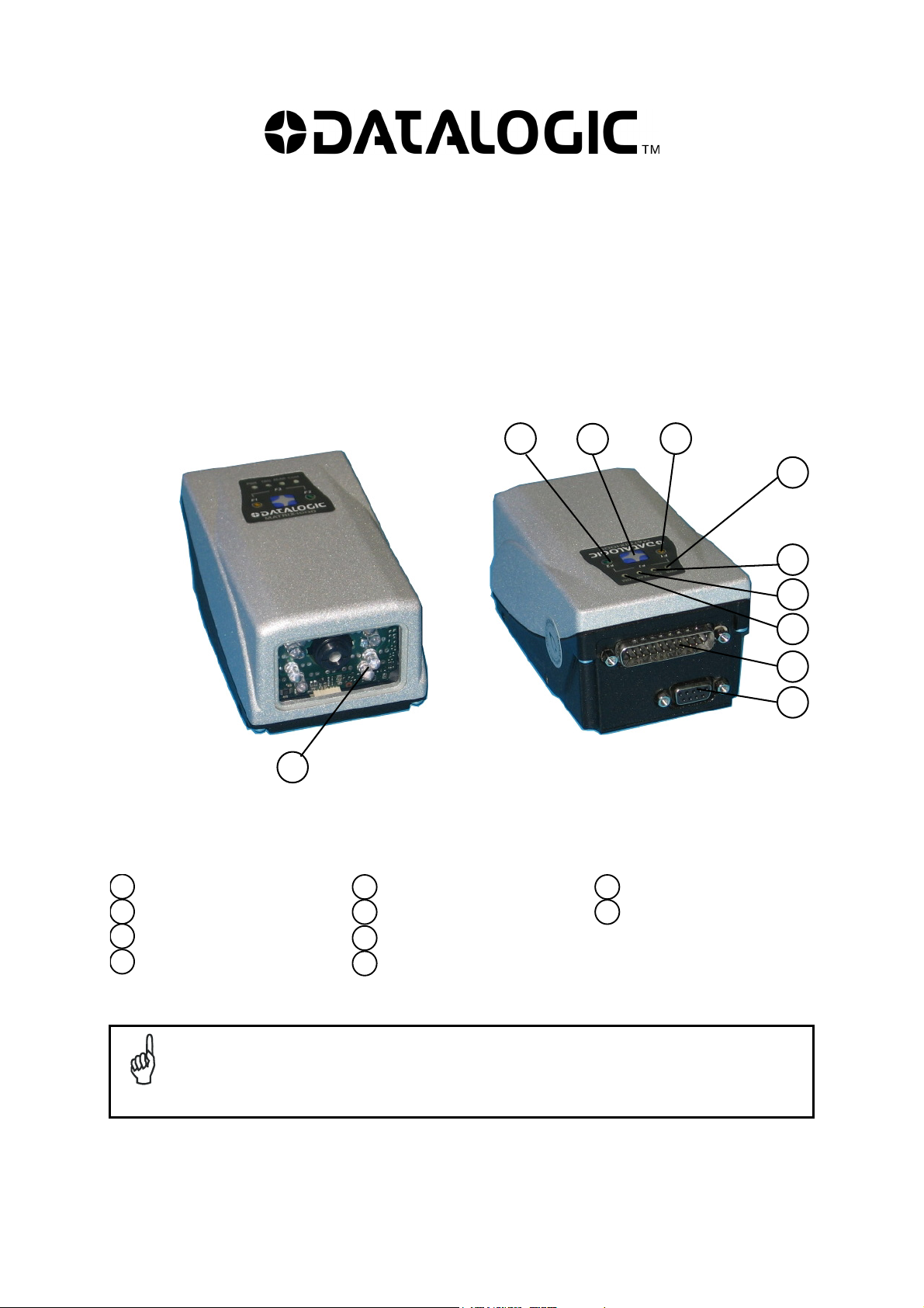
Reading Window
1
F2 LED
2
Keypad button
3
F1 LED
4
This manual illustrates a Stand Alone application. For Multiplexer Layouts and for a complete
reader configuration using VisiSet™ configuration program, refer to the Matrix-1000™ Reference
Manual available on the CD. This manual is also downloadable from the Web at
NOTE
www.automation.datalogic.com/matrix1000.
8
9
10
1
Matrix-1000™ – GENERAL VIEW
Power On LED
5
External Trigger LED
6
Good Read LED
7
Communication LED
8
Main/Auxiliary Interface
9
uxiliary Interface
10
Page 2

MATRIX-1000™ QUICK GUIDE
STEP 1 – CONNECT THE SYSTEM
To connect the system in a Stand Alone configuration, you need the hardware indicated in Figure 1. In this layout
the data is transmitted to the Host on the RS232 auxiliary serial interface which is also used for reader
configuration by running VisiSet™.
When One Shot or Phase Mode Operating mode is used, the reader is activated by an External Trigger
(photoelectric sensor) when the object enters its reading zone.
CAB-600X
Matrix-1000™
P.S.*
* External Trigger or Presence Sensor (for One Shot or Phase mode)
Figure 1 – Matrix-1000™ in Stand Alone Layout
CBOX-100
PG 6000
Aux Interface
Local Host
C-BOX 100 Pinout for Matrix-1000™
The table below gives the pinout of the C-BOX 100 terminal block connectors. Use this pinout when the Matrix1000™ reader is connected by means of the C-BOX 100:
C-BOX 100 Terminal Block Connectors
Power Outputs
1, 3, 5 VS 21, 22 NC
2, 4, 6 GND 23, 24 NC
7, 8 EARTH GROUND 25 OUT 3+
20, 40 Reserved 26 OUT 3-
Inputs Auxiliary Interface RS232
27 EXT TRIG A (polarity insensitive) 35 TX AUX
28 EXT TRIG B (polarity insensitive) 37 RX AUX
29, 30 NC 38,39 GND
31, 33 NC
32, 34 NC 11, 15 RTX 485+
36 NC 12, 16 RTX 485-
17 NC
18 NC
10, 14, 19 SGND
9, 13 RS485 Cable Shield
Main Interface
RS485 Half Duplex
CAUTION
CAUTION
2
Do not connect GND and SGND to different (external) ground references. GND and SGND
are internally connected through filtering circuitry which can be permanently damaged if
subjected to voltage drops over 0.8 Vdc.
When connected to a C-BOX 3x0/4x0
Auxiliary Interface. The Matrix-1000™ 9-pin Auxiliary port connector cannot be used for
communication (i.e. configuration through VisiSet™). To configure Matrix-1000™ through
the 9-pin connector inside the C-BOX 3x0/4x0, the C-BOX 3x0/4x0 must first be
configured. See the relative C-BOX Installation Manual for details.
, Matrix-1000™ can only communicate through its
Page 3
MATRIX-1000™ QUICK GUIDE
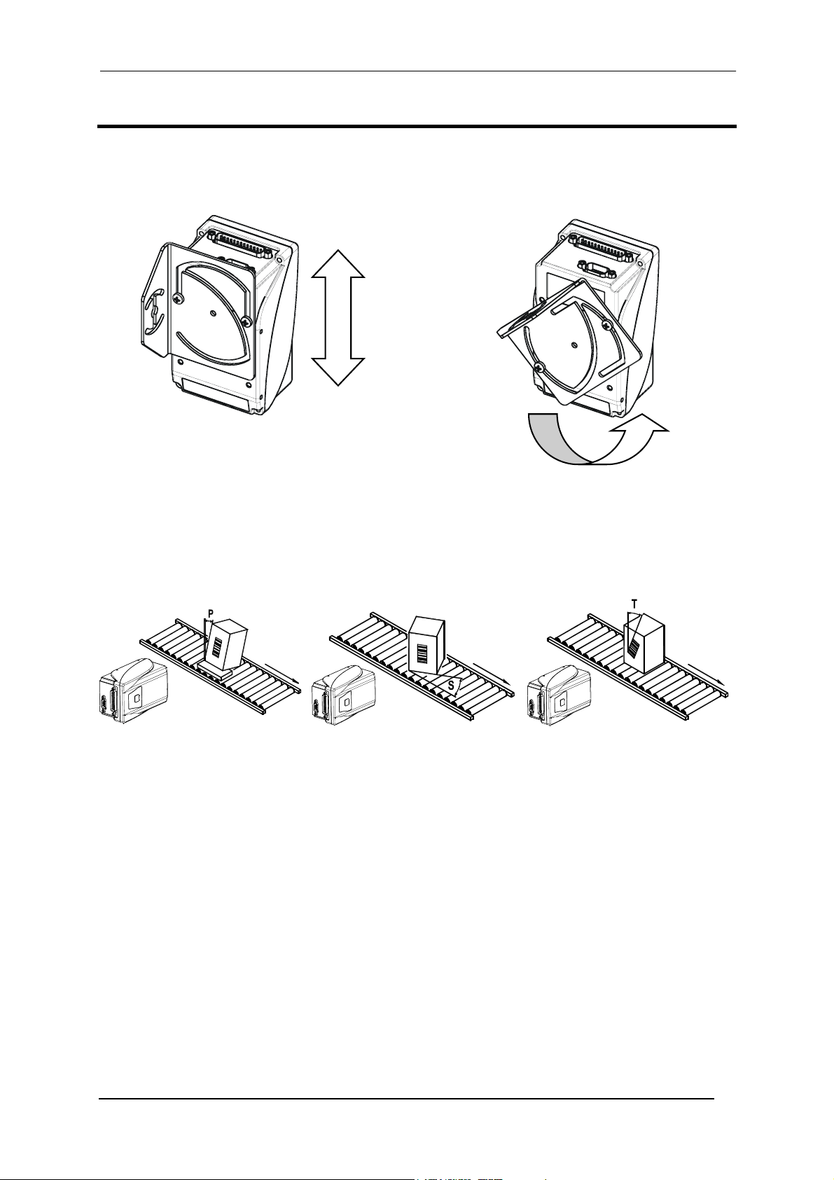
STEP 2 – MOUNTING AND POSITIONING THE SYSTEM
1. To mount the Matrix-1000™, use the mounting bracket to obtain the most suitable position for the reader as
shown in the figures below.
2. When mounting the Matrix-1000™ take into consideration these three ideal label position angles: Pitch or Skew
10° to 20° and Tilt 0°, although the reader can read a code at any Tilt angle.
Minimize Assure at least 10° Minimize
3. Refer to the Reading Features in the Appendix of this Quick Reference Guide to determine the distance your
reader should be positioned at.
Figure 2 - Positioning with Mounting Bracket
Figure 3 – Pitch, Skew and Tilt Angles
3
Page 4
MATRIX-1000™ QUICK GUIDE
STEP 3 – AUTO-LEARNING CONFIGURATION
An autolearning procedure is available to reduce installation time.
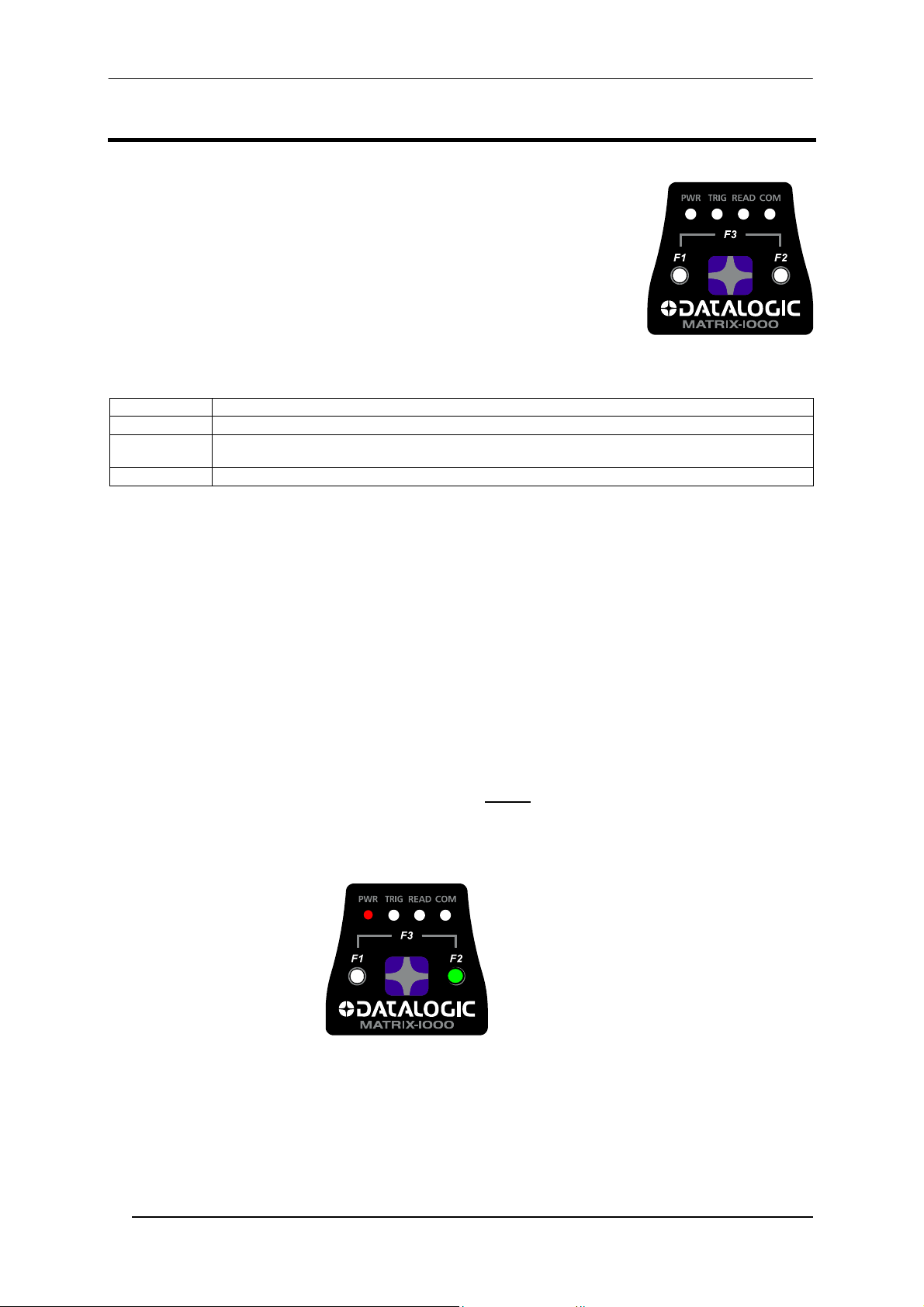
Status and diagnostic information are clearly presented by means of four colored
LEDs, whereas the single push button and F1 and F2 LEDs give immediate access
to the following relevant functions:
• Positioning (F1) gives visual feedback from the F1 LED to help center the
code in the reader's FOV without external tools or software programs
• Auto Learn (F2) to self-detect and auto-configure calibration and code
setting parameters
• Restore Default (F3) to return to factory default settings
The colors and meaning of the four status LEDs are illustrated in the following table:
PWR (red) This LED indicates the device is powered
TRIG (yellow) This LED indicates the external trigger activity
READ (red)
COM (green) This LED indicates active communication on the main serial port.
AUTO LEARN
If you are configuring your reader using the Auto Learn procedure:
1. Place the desired code in front of the reader at the correct reading distance (depending on the model, see the
Reading Features table in the Appendix of this Quick Reference Guide).
2. Enter the Auto Learn function (F2) by pressing and holding the push button until only the F2 LED is on.
3. Release the button to enter the Auto Learn function.
Once entered, the reader acquires an image and automatically configures the optimal exposure and gain
parameters as well as detecting and recognizing the code, which is presented to it. The F2 LED blinks during
this process.
4. At the end of the procedure, the new configuration parameters will be stored to permanent memory, the F2
LED remains on continuously and then the function automatically exits, the F2 LED turns off.
If the Auto Learn calibration cannot be reached within a short timeout (max. 1 minute), Matrix-1000™ will exit
without saving the configuration parameters, the F2 LED will not
blinking.
To cancel the Auto Learn function without saving the configuration parameters, press and hold the keypad button
at any time during the procedure: the F2 LED will stop blinking.
This LED confirms successful reading. It is also used to signal successful startup. At power on this LED
turns on and after a few seconds turns off. If the startup is not successful, this LED remains on.
remain on continuously but it will just stop
Auto Learn (F2)
green
Figure 4 – Auto Learn Function
Repeat the procedure if needed, to program different code symbologies, however you must present only one
code at a time to the reader.
Matrix-1000™ is able to decode any code symbology in its library with this procedure.
4
Page 5
MATRIX-1000™ QUICK GUIDE
If your application has been configured using Auto Learn, your reader is ready. If necessary you
can use VisiSet™ for advanced reader configuration.
NOTE
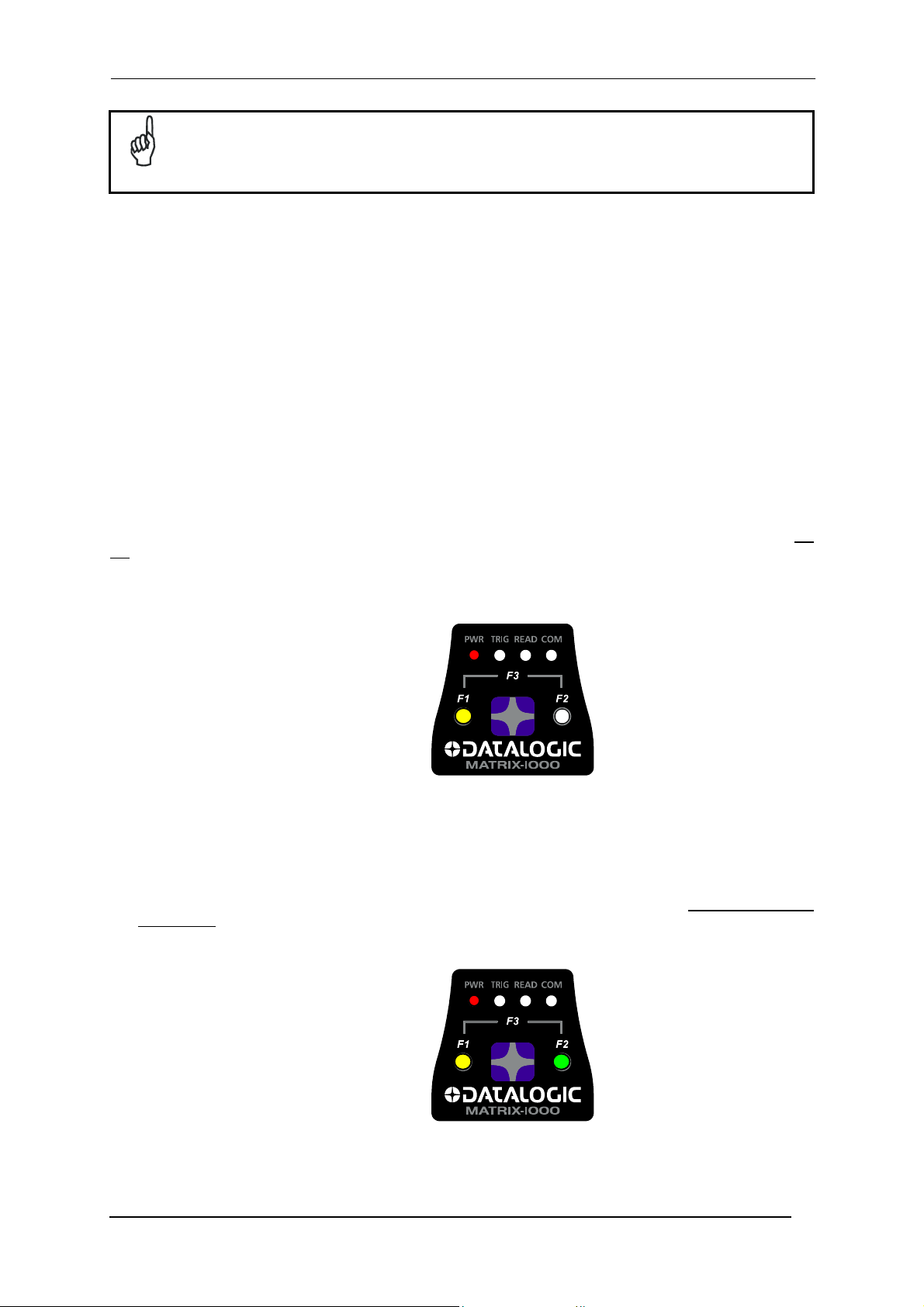
POSITIONING (OPTIONAL)
At the end of the Auto Learn procedure, you can use the Positioning procedure to center the code with respect to
the reader's FOV.
1. While the desired code is in front of the reader at the correct reading distance, enter the Positioning function
(F1) by pressing and holding the push button until only the F1 LED is on.
2. Release the button to enter the Positioning function.
Once entered, the reader continuously acquires images and gives visual feedback using the F1 LED to
indicate when the code is centered with respect to the reader's FOV. Slow blinking means that the positioning
value must be improved.
3. To obtain the best value in terms of positioning, move the code and/or the reader so as to position the code
as close as possible to the center of the Field of View, keeping the correct focus distance. Check F1 LED
blinking: the best code positioning corresponds to fast (almost continuous) blinking.
4. After a short timeout the function automatically exits, the F1 LED remains on continuously and then stops
blinking.
If no valid code is present in the FOV, after about 3 minutes, Matrix-1000™ will automatically exit, the F1 LED will
not remain on continuously but it will just stop blinking.
To cancel the Positioning function, press and hold the keypad button at any time during the procedure: the F1
LED will stop blinking.
Positioning (F1)
yellow
Figure 5 – Positioning Function
RESTORE DEFAULT (OPTIONAL)
At any time you can use the Restore Default procedure to return the reader to the factory default settings.
1. Enter the Restore Default function (F3) by pressing and holding the push button until both the F1 and F2
LEDs are on.
2. Release the button to perform the Restore Default function.
Restore Default (F3)
= F1 yellow +
F2 green
Figure 6 – Restore Default Function
5
Page 6
MATRIX-1000™ QUICK GUIDE
STEP 4 – INSTALLING VISISET™ CONFIGURATION PROGRAM
VisiSet™ is a Datalogic reader configuration tool providing several important advantages:
• Autolearning Wizard for new users;
• Defined configuration directly stored in the reader;
• Communication protocol independent from the physical interface allowing to consider the reader as a remote
object to be configured and monitored.
To install VisiSet™, turn on the PC that will be used for the configuration, running Windows 98, 2000/NT or
XP, then insert the VisiSet™ CD-ROM, wait for the CD to autorun and follow the installation procedure.
This configuration procedure assumes a laptop computer, running VisiSet™, is connected to the reader's auxiliary
port.
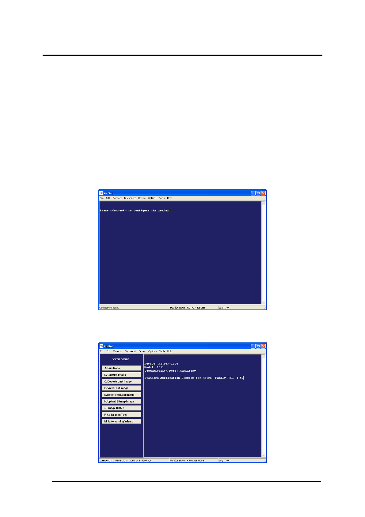
WIZARD FOR QUICK READER SETUP
After installing and running the VisiSet™ software program the following window:
Figure 7 - VisiSet™ Opening Window
Set the communication parameters from the "Options" menu. Then select "Connect", the following window
appears:
Figure 8 - VisiSet™ Main Window After Connection
6
Page 7

MATRIX-1000™ QUICK GUIDE
The Autolearning Wizard option is advised for rapid configuration or for new users. It allows reader configuration
in a few easy steps.
1. Select the Autolearning Wizard button from the Main menu.
2. Place the desired code in front of the reader at the correct reading distance (depending on the model, see the
Reading Features table in the Appendix of this Quick Reference Guide).
3. Press the "Positioning" button. The reader continuously acquires images and gives visual feedback in the
view image window to indicate when the code is centered with respect to the reader's FOV. Move the reader
(or code) to center it. Press the Positioning button again to stop positioning.
4. Select a Calibration Mode choice and press the "Calibrate" button.
3
4
5
Autolearning
Result
The reader flashes once acquiring the image and auto determines the best exposure and gain settings. If the
code symbology is enabled by default, the code will also be decoded.
7
Page 8

MATRIX-1000™ QUICK GUIDE
5. If the code symbology is not enabled by default, select a Code Setting Mode choice and press the "Code
Setting" button.
The Autolearning Result section of the Autolearning Wizard window shows the parameter settings and the code
type results.
6. Select a Saving Options choice and press the "Save" button.
7. Close the AutoLearning Wizard.
If your application has been configured using the VisiSet™ Autolearning Wizard, your reader is
ready. If necessary you can use VisiSet™ for advanced reader configuration.
NOTE
8
Page 9

MATRIX-1000™ QUICK GUIDE
ADVANCED READER CONFIGURATION
For further details on advanced product configuration, refer to the complete Reference Manual on the installation
CD-ROM or downloadable from the web site through this link: www.automation.datalogic.com/matrix1000.
The following are alternative or advanced reader configuration methods:
ADVANCED CONFIGURATION USING VISISET™
Advanced configuration can be performed through the VisiSet™ program by selecting Device> Get Configuration
From Temporary Memory to open the Parameter Setup window in off-line mode. Advanced configuration is
addressed to expert users being able to complete a detailed reader configuration. The desired parameters can be
defined in the various folders of the Parameter Setup window and then sent to the reader memory (either
Temporary or Permanent):
Figure 9 - VisiSet™ Parameter Setup Window
HOST MODE PROGRAMMING
The reader can also be configured from a host computer using the Host Mode programming procedure, by
commands via the serial interface. See the Host Mode Programming file on the CD-ROM.
ALTERNATIVE LAYOUTS
If you need to install a Multiplexer network refer to the Matrix-1000™ Reference Manual.
9
Page 10

MATRIX-1000™ QUICK GUIDE
APPENDIX
READING FEATURES
READING FEATURES
Frame Rate Up to 30 frames/sec. with VGA images
Readable
Codes per
Frame
Pitch
Tilt
Focus
MODELS
1021 HD 115 (4.53)
1031 SD 155 (6.10)
1041 LD 110 (4.33)
1051 MR 210 (8.26)
(1)
@ Focus Distance
(2)
Pixels per Inch @ Focus Distance
(3)
Measurement Conditions:
• Test Chart: provided with the reader
• Still code at the center of the FOV
• Code Symbology: Data Matrix ECC 200
Distance
mm (in)
Field of View
mm (in)
25 × 19
(0.98 × 0.75)
34 × 26
(1.34 × 1.02)
54 x 40
(2.13 × 1.57)
95 × 70
(3.74 × 2.75)
(1)
ppi
653 0.10 (4) 0.19 (7.5) 105 (4.13) 125 (4.92)
478 0.15 (6) 0.25 (10) 135 (5.31) 180 (7.08)
300 0.20 (8) 0.38 (15) 90 (3.45) 140 (5.51)
170 0.30 (12) 0.60 (24) 150 (5.90) 250 (9.84)
Depending on the code resolution, symbology and number of characters in the code, the Reading Area can be
different from the FOV.
Up to 100
10° - 35°
0° - 360°
Typ. Linear
and Stacked
(2)
• Code Resolution: Typ. 2D Code Resolution
• Tilt Angle: 45°
• Skew Angle: 15°
• Image Processing Mode: Advanced Code Setting
Code
Resolution
mm (mils)
Resolution
mm (mils)
Typ. 2D
Code
Reading Distance
mm (in)
min. max.
(3)
10
Page 11

MATRIX-1000™ QUICK GUIDE
TECHNICAL FEATURES
ELECTRICAL FEATURES
Power
Supply Voltage 10 to 30 Vdc
Power Consumption 4 W max.; 2.5 W typical
Communication Interfaces
Main - RS485 half-duplex
Auxiliary - RS232
Input
External Trigger
Outputs
OUT3 Opto-coupled
OPTICAL FEATURES
Image Sensor Matrix CCD
Image Format VGA (640x480)
Lighting System LED array
Wavelength 630 ~ 670 nm
Max LED Output Power 0.7 mW to EN60825-1
LED Safety Class Class 1 to EN60825-1
USER INTERFACE
LED Indicators PWR, TRIG, READ, COM, F1, F2
Keypad Button Configurable via VisiSet™
SOFTWARE FEATURES
Readable Code Symbologies
1-D and stacked 2-D POSTAL
• PDF417 Standard and Micro PDF417
• Code 128 (EAN 128)
• Code 39 (Standard and Full ASCII)
• Interleaved 2 of 5
• Codabar • MAXICODE • PLANET
• Code 93 • Aztec Code • POSTNET, POSTNET (+BB)
• Pharmacode
• EAN-8/13 - UPC-A/E
(including Addon 2 and Addon 5)
• GS1 DataBar (RSS) Family
• Composite Symbologies
Operating Mode ONE SHOT, CONTINUOUS, PHASE MODE
Configuration Mode By means of VisiSet™ configuration software
Parameter Storage Permanent memory (Flash)
• Data Matrix ECC 200
(Standard)
• QR Code
(Standard)
• Microglyph
(this symbology requires an
activation procedure – contact your
local Datalogic Automation
distributor for details)
SYMBOL VERIFICATION
Standard Supported Symbologies
ISO/IEC 16022 Data Matrix ECC 200
ISO/IEC 18004 QR Code
MECHANICAL FEATURES
Dimensions 121 x 73 x 57 mm (4.76 x 2.87 x 2.24 in.)
Weight 330 g. (11.6 oz.)
Material Magnesium alloy
ENVIRONMENTAL FEATURES
Operating Temperature
Storage Temperature
Max. Humidity 90% non condensing
Vibration Resistance IEC 68-2-6 test FC 14 mm @ 2 to 10 Hz; 1.5 mm @ 13 to 55 Hz
2 g @ 70 to 200 Hz; 2 hours on each axis
Shock Resistance IEC 68-2-27 test EA 30 g; 11 ms; 3 shocks on each axis
Protection Class IP64 (sealed connectors required)
2400 to 115200 bit/s
2400 to 115200 bit/s
Opto-coupled and polarity insensitive
• Australia Post
• Royal Mail 4 State Customer
• Kix Code
• Japan Post
• POSTNET + PLANET,
POSTNET (+BB) + PLANET
0 to 40 °C (32 to 104 °F)
-20 to 70 °C (-4 to 158 °F)
11
Page 12
MATRIX-1000™ QUICK GUIDE
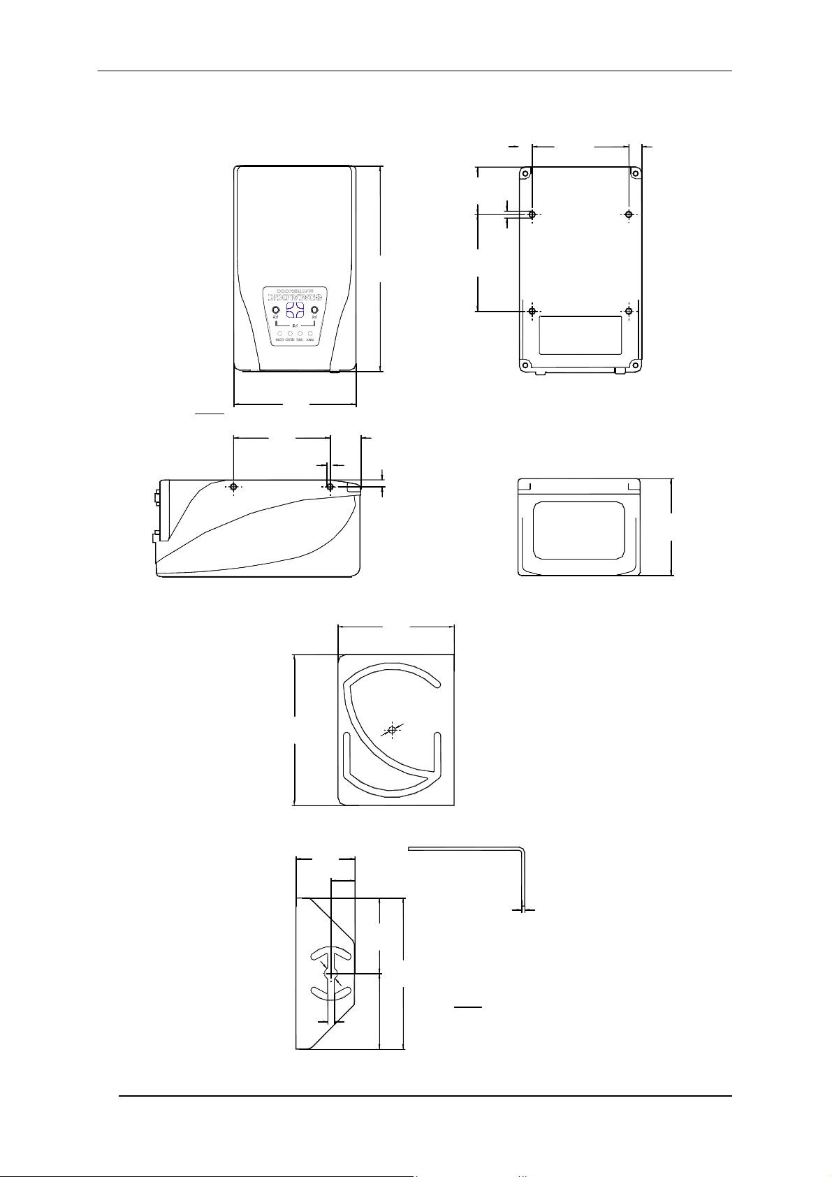
MECHANICAL DIMENSIONS
73
mm
[inch]
[2.87]
57
[2.24]
M4 x 5 n°4
[0.71]
18.1
121
[4.76]
= =
28.1
[1.11]
M4 x 5 n°4
57
[2.24]
4
[0.16]
57
[2.24]
57
[2.24]
Figure 10 – Matrix-1000™ Overall Dimensions
95
[3.74]
37
[1.46]
15
[0.59]
73
[2.87]
2
.
4
]
Ø
7
1
.
0
Ø
[
2
[0.08]
12
47.5
[1.87]
Ø
[
Ø
8
.
0
2
.
3
2
]
4.2
[0.17]
95
[3.74]
mm
47.5
[1.87]
[inch]
Figure 11 – Mounting Bracket Overall Dimensions
Page 13

MATRIX-1000™ QUICK GUIDE
PATENTS
This product is covered by one or more of the following patents:
U.S. patent: 6,512,218 B1; 6,616,039 B1
European patent: 999,514 B1; 1,014,292 B1.
SERVICES AND SUPPORT
Datalogic provides several services as well as technical support through its website. Log on to
www.automation.datalogic.com and click on the links
• PRODUCTS
Search through the links to arrive at your product page where you can download specific Manuals and
Software & Utilities
- VisiSet™ a utility program, which allows device configuration using a PC. It provides RS232 interface
configuration.
including:
• SERVICES & SUPPORT
- Datalogic Services
- Authorised Repair Centres
- Warranty Extensions and Maintenance Agreements
indicated for further information including:
• CONTACT US
E-mail form and listing of Datalogic Subsidiaries
COMPLIANCE
EMC COMPLIANCE
In order to meet the EMC requirements:
• connect reader chassis to the plant earth ground by means of a flat copper braid shorter than 100 mm;
• connect the main interface cable shield to pin 1 of the reader 25-pin connector;
• use two clip-on ferrite sleeves (type Stewart 28A2029-0A0) on the main interface cable near the reader
25-pin connector;
POWER SUPPLY
This product is intended to be installed by Qualified Personnel only.
This product is intended to be connected to a UL Listed Computer which supplies power directly to the reader or a
UL Listed Direct Plug-in Power Unit marked LPS or “Class 2”, rated 10 to 30 V, minimum 1 A.
CE COMPLIANCE
Warning: This is a Class A product. In a domestic environment this product may cause radio interference in
which case the user may be required to take adequate measures.
WEEE COMPLIANCE
13
Page 14

DECLARATION OF CONFORMITY
Datalogic Automation S.r.l.
Via S. Vitalino 13
40012 - Lippo di Calderara
dichiara che
declares that the
déclare que le
bescheinigt, daß das Gerät
declare que el
Matrix-1XXX; e tutti i suoi modelli
and all its models
et tous ses modèles
und seine Modelle
y todos sus modelos
sono conformi alle Direttive del Consiglio Europeo sottoelencate:
are in conformity with the requirements of the European Council Directives listed below:
sont conformes aux spécifications des Directives de l'Union Européenne ci-dessous:
der nachstehend angeführten Direktiven des Europäischen Rats:
cumple con los requisitos de las Directivas del Consejo Europeo, según la lista siguiente:
89/336/EEC EMC Directive e 92/31/EEC, 93/68/EEC emendamenti successivi
and further amendments
et ses successifs amendements
und späteren Abänderungen
y succesivas enmiendas
Basate sulle legislazioni degli Stati membri in relazione alla compatibilità elettromagnetica ed alla sicurezza dei prodotti.
On the approximation of the laws of Member States relating to electromagnetic compatibility and product safety.
Basée sur la législation des Etats membres relative à la compatibilité électromagnétique et à la sécurité des produits.
Über die Annäherung der Gesetze der Mitgliedsstaaten in bezug auf elektromagnetische Verträglichkeit und Produktsicherheit
entsprechen.
Basado en la aproximación de las leyes de los Países Miembros respecto a la compatibilidad electromagnética y las Medidas
de seguridad relativas al producto.
Questa dichiarazione è basata sulla conformità dei prodotti alle norme seguenti:
This declaration is based upon compliance of the products to the following standards:
Cette déclaration repose sur la conformité des produits aux normes suivantes:
Diese Erklärung basiert darauf, daß das Produkt den folgenden Normen entspricht:
Esta declaración se basa en el cumplimiento de los productos con las siguientes normas:
EN 55022 (Class A ITE), August 1994:
Amendment A1 (Class A ITE), October 2000:
EN 61000-6-2, October 2001: E
Lippo di Calderara, April 2nd, 2007 Lorenzo Girotti
Bologna - Italy
IMITS AND METHODS OF MEASUREMENTS OF RADIO DISTURBANCE
L
CHARACTERISTICS OF INFORMATION TECHNOLOGY EQUIPMENT
LECTROMAGNETIC COMPATIBILITY (EMC)
ART 6-2: GENERIC STANDARDS - IMMUNITY FOR INDUSTRIAL
P
ENVIRONMENTS
Product & Process Quality Manager
07
821000935 (Rev. F1)
 Loading...