

Page 1

Marvis™
Application Note
Marking and Reading System
Page 2

Datalogic S.r.l.
Via S. Vitalino, 13
40012 Calderara di Reno — Italy
Tel. +39 051 3147011
Fax +39 051 3147205
Marvis™ Application Manual
Original Instructions
Ed.: 04/2019
This manual refers to Lighter™ Suite version 7.1.3 and later.
© 2018-2019 Datalogic S.p.A. and/or its affiliates
ALL RIGHTS RESERVED. Without limiting the rights under copyright, no part of this docu-
mentation may be reproduced, stored in or introduced into a retrieval system, or transmitted
in any form or by any means, or for any purpose, without the express written permission of
Datalogic S.p.A. and/or its affiliates.
Datalogic and the Datalogic logo are registered trademarks of Datalogic S.p.A. in many countries, including the U.S.A. and the E.U.
Arex™ 400, Arex™, UniQ™, Vlase™, Matrix (120™, 210N™, 220™, 300N™, 410N™) and Lighter™
Suite are trademarks of Datalogic S.p.A.and/or its affiliates. All other trademarks and bands
are property of their respective owners.
Datalogic shall not be liable for technical or editorial errors or omissions contained herein, nor
for incidental or consequential damages resulting from the use of this material.
Page 3

Table of Contents
CONVENTIONS.......................................................................................................................................................................VI
INTRODUCTION...................................................................................................................................................................... 1
About This Document ...................................................................................................................................................................... 2
Restrictions ....................................................................................................................................................................................... 2
SUPPORTED TOPOLOGIES AND OPERATIONS.................................................................................................................... 3
Marvis™ Configuration ..................................................................................................................................................................... 4
Vlase™ and Matrix 220™/300N™/410N™ ................................................................................................................................ 4
Arex™ and Matrix 220™/300N™/410N™ .................................................................................................................................. 5
UniQ™ and Matrix 220™/300N™/410N™ ................................................................................................................................. 6
Arex™ 400 and Matrix 220™/300N™/410N™ .......................................................................................................................... 7
HARDWARE INSTALLATION ................................................................................................................................................. 9
Mounting Instructions for Matrix ................................................................................................................................................. 10
Mechanical assembly on Arex™ laser marker ..................................................................................................................... 10
Mechanical assembly on UniQ™ laser marker .................................................................................................................... 13
Mechanical assembly on Arex™ 400 laser marker .............................................................................................................. 16
Fixing the Matrix 300N™, 410N™ to the bracket .................................................................................................................. 19
Fixing the Matrix 220™ to the bracket .................................................................................................................................. 20
Connecting Matrix 220™, 300N™ and 410N™ ................................................................................................................................ 21
Connecting Matrix to the Ethernet ...................................................................................................................................... 21
Connecting to Matrix ..................................................................................................................................................... 21
Connecting to Vlase™ ..................................................................................................................................................... 21
Connecting to Arex™ ....................................................................................................................................................... 22
Connecting to UniQ™ ...................................................................................................................................................... 22
Connecting to Arex™ 400 ............................................................................................................................................... 23
Connecting Matrix to power supply ..................................................................................................................................... 24
Connecting to Matrix ..................................................................................................................................................... 24
Connecting to Vlase™, Arex™ and UniQ™ laser markers ............................................................................................. 24
Connecting to Arex™ 400 laser marker ........................................................................................................................ 24
Connecting LED Ring Light ID (optional) .............................................................................................................................. 25
Vlase™, Arex™ and UniQ™ laser markers ...................................................................................................................... 25
Arex™ 400 laser marker ................................................................................................................................................. 26
SOFTWARE CONFIGURATION............................................................................................................................................. 27
How To Configure Your Marvis™ System ..................................................................................................................................... 28
How To Test, Mark and Validate Your Document ....................................................................................................................... 34
Marking and Validation Statistics ................................................................................................................................................ 36
Troubleshooting ............................................................................................................................................................................. 38
HELP................................................................................................................................................................. 41
Photometric Adjustment ............................................................................................................................................................... 42
Setting ..................................................................................................................................................................................... 42
Results .................................................................................................................................................................................... 43
Quality Grade Training ................................................................................................................................................................... 45
Industrial traceability ............................................................................................................................................................. 45
The Code Grading process ..................................................................................................................................................... 45
Quality parameters of metrics .............................................................................................................................................. 46
CC - Cell Contrast ........................................................................................................................................................... 46
CM - Cell Modulation ..................................................................................................................................................... 46
FPD - Fixed Pattern Damage ........................................................................................................................................ 46
UEC - Unused Error Correction ..................................................................................................................................... 46
Application Note iii
Page 4

Contents
PG - Print Growth ...........................................................................................................................................................46
ANU - Axial Non-Uniformity ..........................................................................................................................................46
MR - Minimum Reflectance ..........................................................................................................................................46
GNU - Grid Non-Uniformity (GNU) ................................................................................................................................47
Verification process ................................................................................................................................................................47
Verification in production environments .............................................................................................................................47
In-line validation: a real example ..........................................................................................................................................48
MARVIS™ advantages: training on real sample ...................................................................................................................49
MARVIS™ advantages: single metric quality grade analysis ..............................................................................................49
MARVIS™ advantages: statistic threshold ............................................................................................................................50
ABOUT LED RING LIGHT ID.............................................................................................................................. 51
General Specification ......................................................................................................................................................................52
IEC62471-1 Compliance .................................................................................................................................................................52
iv
Marvis™
Page 5

Contents
Application Note v
Page 6
Conventions
Warnings
High Voltage
Laser Caution
ESD
Notes
This symbol identifies a hazard or procedure that, if incorrectly performed, could cause personal injury or result in
equipment damage. It is also used to bring the user’s attention to details that are considered IMPORTANT.
This symbol alerts the user they are about to perform an
action involving,
against an action that could result in damage to devices or
electrical shock.
This symbol alerts the user they are about to perform an
action involving possible exposure to laser light radiation.
This symbol identifies a procedure
measures to prevent Electrostatic Discharge (ESD) e.g., use an
ESD wrist strap. Circuit boards are most at risk. Please follow
ESD procedures.
This symbol draws attention to details or procedures that may
be useful in
mance of the hardware or software being discussed.
either a dangerous level of voltage, or to warn
that requires you take
improving, maintaining, or enhancing the perfor-
vi
Marvis™
Page 7

Application Note vii
Page 8

ABOUT THIS DOCUMENT starting on page 2
RESTRICTIONS starting on page 2
Chapter 1
Introduction
1
Marvis™
Page 9
About This Document
This document describes the implementation of a laser marker with a reading
system. The result of this system is defined as MARVIS™.
Refer to the associated reference manuals for additional information about setup,
maintenance and troubleshooting. Other related manuals are:
Vlase™ User’s Manual; Arex™ User's Manual; UniQ™ User's Manual; Arex™ 400 User’s
NOTE
Manual; Matrix 120™ User's Manual; Matrix 210N™ User's Manual; Matrix 220™ User's
Manual; Matrix 300N™ User's Manual; Matrix 410N™ User's Manual; Lighter™ Suite software User's Manual
Restrictions
The MARVIS™ solution is available for retrofit of existing Datalogic Laser Markers
and Readers as shown in the following table:
FAMILY DESCRIPTION MODELS NOTES
Arex™ Arex™ XX00-1X42 2015
Vlase™ Vlase™ 1X09-1X42 2016
Arex™ 20MW Arex™ A200-XX53
UniQ™ UniQ™ 1150-1X40
Arex™ 400 Arex™ XXX-XX4
Matrix 120™ Matrix 120™ X1X-01X YAG filter
Matrix 210N™ Matrix 210N™ 2XX-X1X
Matrix 220™ Matrix 220™ 3XX-010
Matrix 300N™ Matrix 300N™ 4XX-01X 472-012, 473-012, 482-012, 483-013 YAG filter
Matrix 300N™ Matrix 300N™ 4XX-01X
Matrix 410N™ Matrix 410N™ XXX-X1X
About This Document
472-010, 472-011, 473-010, 473-011,482-010, 482-011,
483-010, 483-011
→
→
NO YAG filter
W
ARNING
W
ARNING
The DPM illuminator is always recommended.
If application codes must be read which are produced
by Laser Marking in real time,
use Matrix models incorporating YAG Filters in order to avoid burning the CMOS sensor.
Application Note 2
Page 10

Chapter 2
Supported Topologies and Operations
MARVIS™ CONFIGURATION starting on page 4
3
Marvis™
Page 11
Marvis™ Configuration
Datalogic allows the integration of its products to create a complete marking and
reading verification system. To make this application possible, it is necessary to
integrate a laser marker (Vlase™, Arex™, UniQ™ or Arex™ 400) with a Matrix
reader (120™, 210N™, 220™, 300N™, 410N™).
Marvis™ Configuration
Datalogic makes available MARVIS™ ADD ON ki
between laser marker and Matrix reader easier. Currently these kits are compatible with Matrix 220™, 300N™ and 410N™. For the integration of Matrix 120N™/
0N™ with the laser marker, contact the technical support.
21
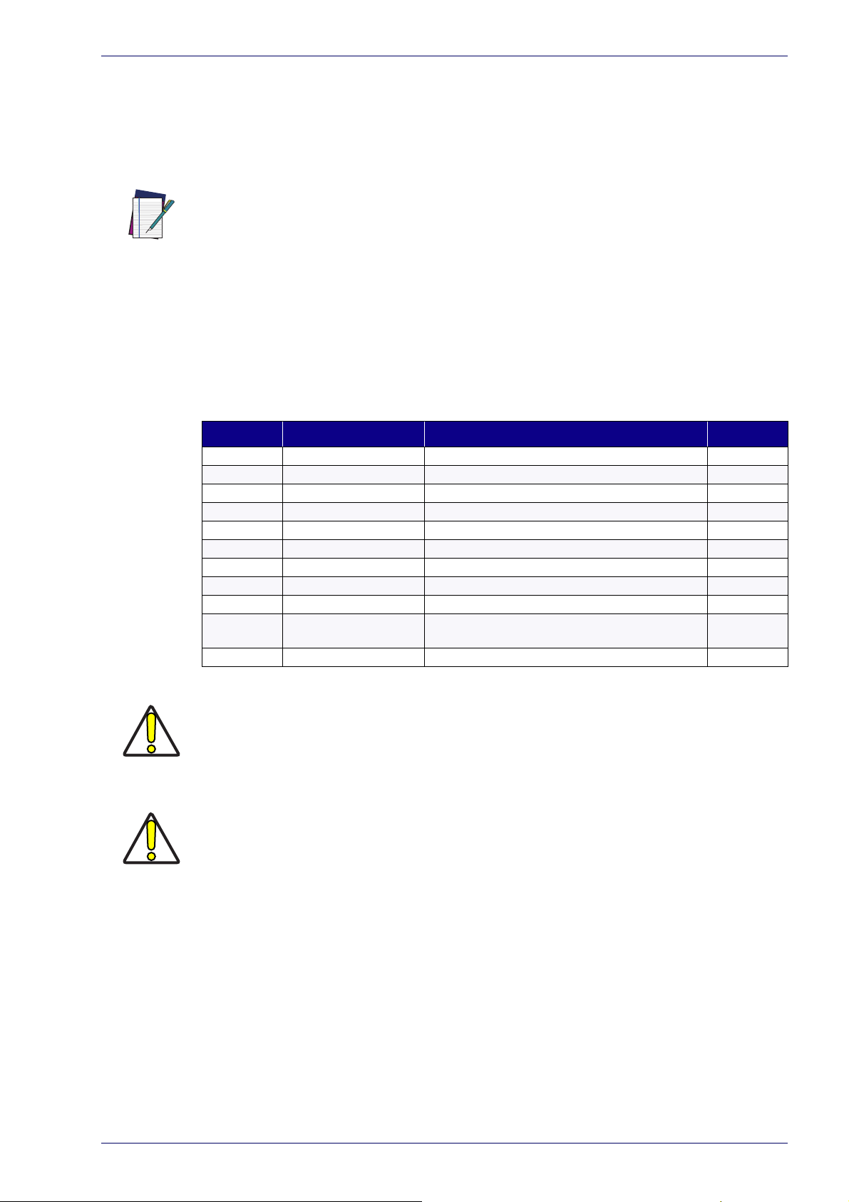
Vlase™ and Matrix 220™/300N™/410N™
ts to make the integration
Figure 1: example of integration between the Vlase™ and the Matrix™.
Figure 2: example of integration between the Vlase™ and the Matrix™ with LED Ring Light ID.
Application Note 4
Page 12
Supported Topologies and Operations
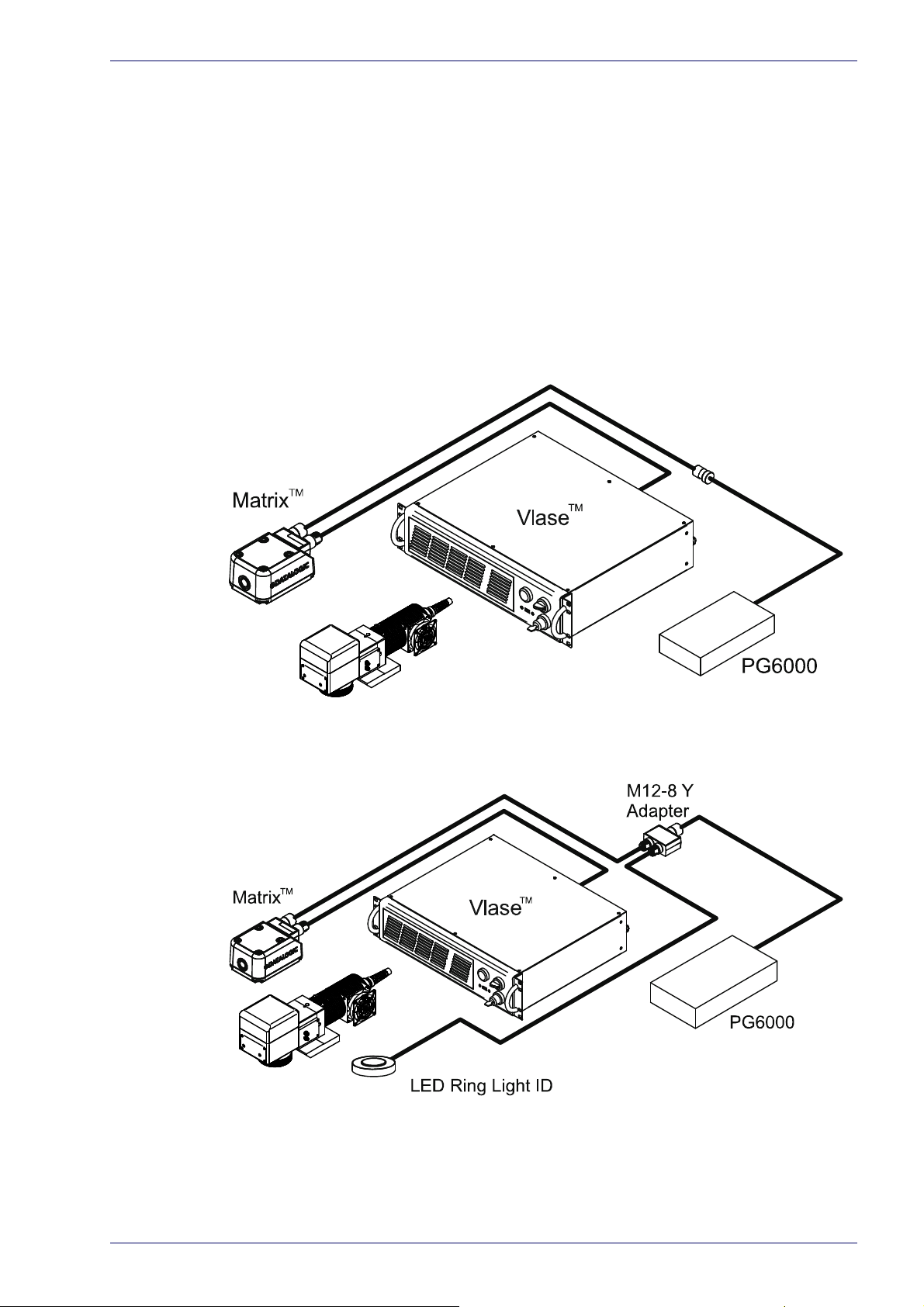
Arex™ and Matrix 220™/300N™/410N™
Figure 3: example of integration between the Arex™ and the Matrix™.
Figure 4: example of integration between the Arex™ and the Matrix™ with LED Ring Light ID.
5
Marvis™
Page 13
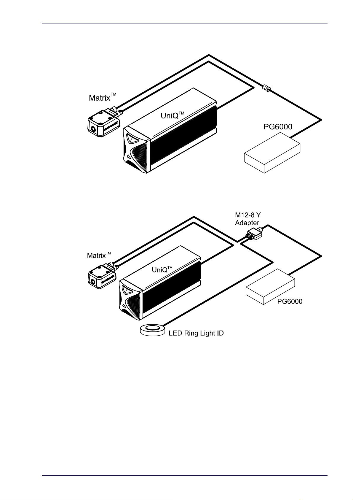
UniQ™ and Matrix 220™/300N™/410N™
Figure 5: example of integration between the UniQ™ and the Matrix™.
Marvis™ Configuration
Figure 6: example of integration between the UniQ™ and the Matrix™ with LED Ring Light ID.
Application Note 6
Page 14
Supported Topologies and Operations
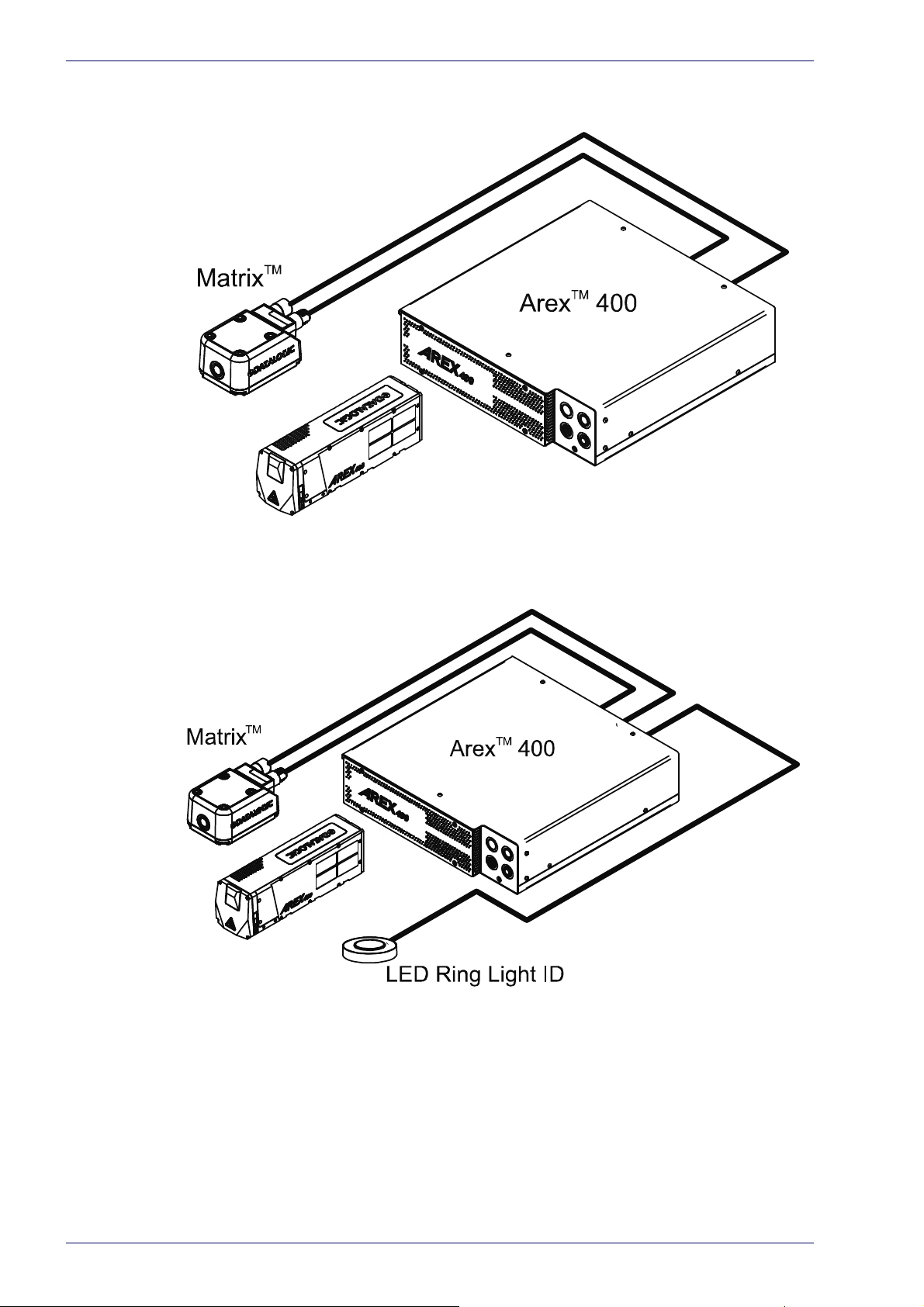
Arex™ 400 and Matrix 220™/300N™/410N™
Figure 7: example of integration between the Arec™ 400 and the Matrix 300N™.
Figure 8: example of integration between the Arex™ 400 and the Matrix™ with LED Ring Light ID.
Figure 9
7
Marvis™
Page 15

Marvis™ Configuration
Application Note 8
Page 16

Chapter 3
Hardware Installation
MOUNTING INSTRUCTIONS FOR MAT RI X starting on page 10
CONNECTING MAT RI X 220™, 300N™ AND 410N™ starting on
page 21
9
Marvis™
Page 17
Mounting Instructions for Matrix
Datalogic makes available MARVIS™ MOUNTING BRACKETS to make the integration between laser marker and Matrix 220™, 300N™ and 410™ readers easier.
Install the individual systems following the instructions present in the relative
stallation manuals. This manual explains what to do in order to obtain a mark
in
and read application.
Mechanical assembly on Arex™ laser marker
At first, mount the LED Ring Light ID (if present) on the bracket:
Mounting Instructions for Matrix
Figure 1: LED Ring Light ID mounting on Arex™.
Application Note 10
Page 18
Hardware Installation
The assembly of the following accessory changes the fixing distance by the value of
the base plate thickness.
W
ARNING
Fix the bracket to the adjustment plate with the supplied screws.
The bracket can be installed in two different positions:
11
Figure 2: Bracket mounting on Arex™.
Marvis™
Page 19

Mounting Instructions for Matrix
Mount the bracket between the Arex™ Scan Head and the fixing plane.
Figure 3: Fixing of Arex™ with bracket on fixing plane.
Application Note 12
Page 20

Hardware Installation
Mechanical assembly on UniQ™ laser marker
At first, mount the LED Ring Light ID (if present) on the bracket:
13
Figure 4: LED Ring Light ID mounting on UniQ™.
Marvis™
Page 21

W
ARNING
Mounting Instructions for Matrix
The assembly of the following accessory modifies the fixing points.
Fix the adjustment plate to the Uniq ™ with the supplied screws as shown:
Figure 5: Fixing adjustment plate on UniQ™.
Application Note 14
Page 22

Hardware Installation
Fix the bracket to the adjustment plate with the supplied screws.
The bracket can be installed in two different positions:
15
Figure 6: Bracket mounting on UniQ™.
Marvis™
Page 23

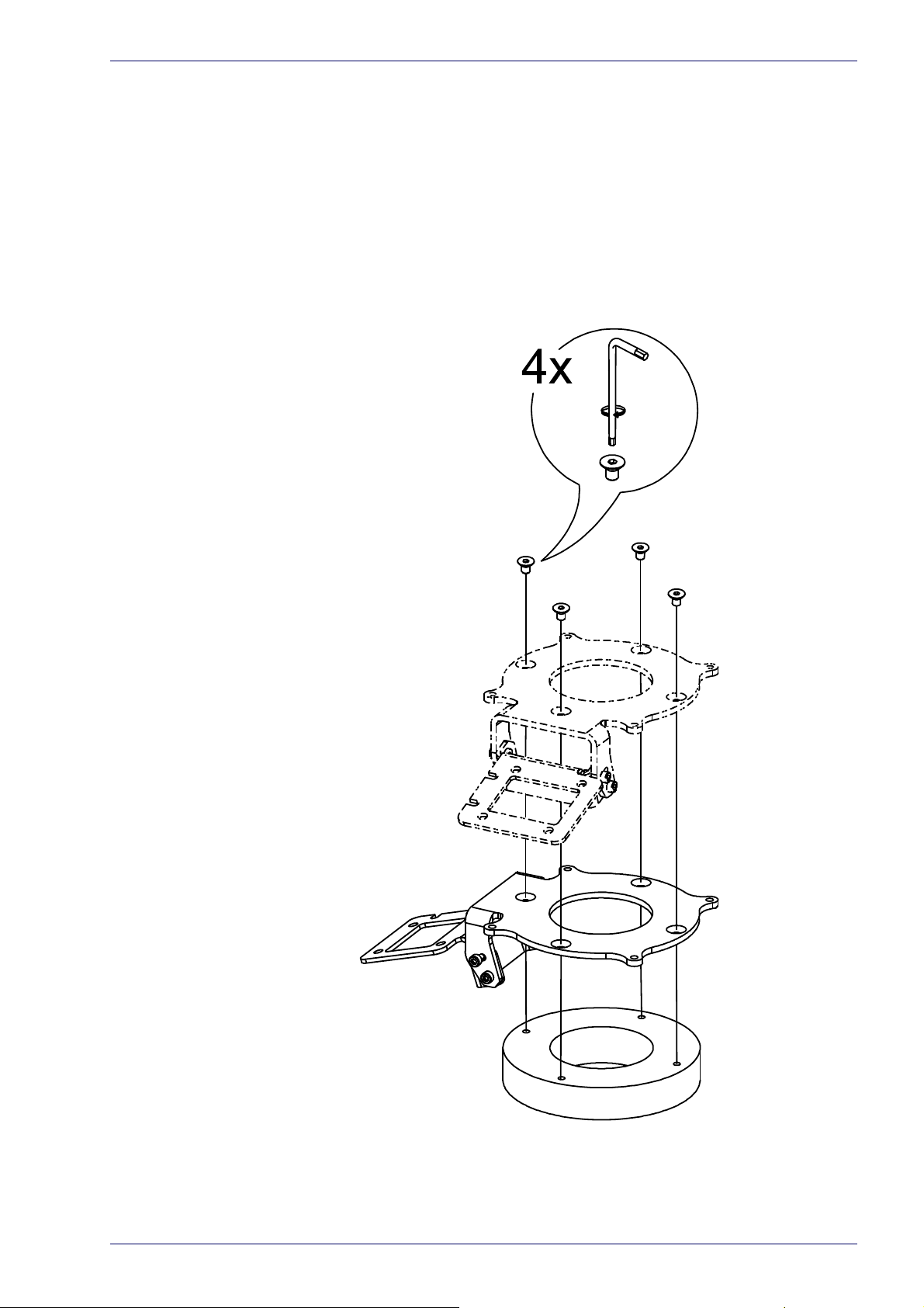
Mechanical assembly on Arex™ 400 laser marker
At first, mount the LED Ring Light ID (if present) on the bracket:
Mounting Instructions for Matrix
Figure 7: LED Ring Light ID mounting on Arex™.
Application Note 16
Page 24

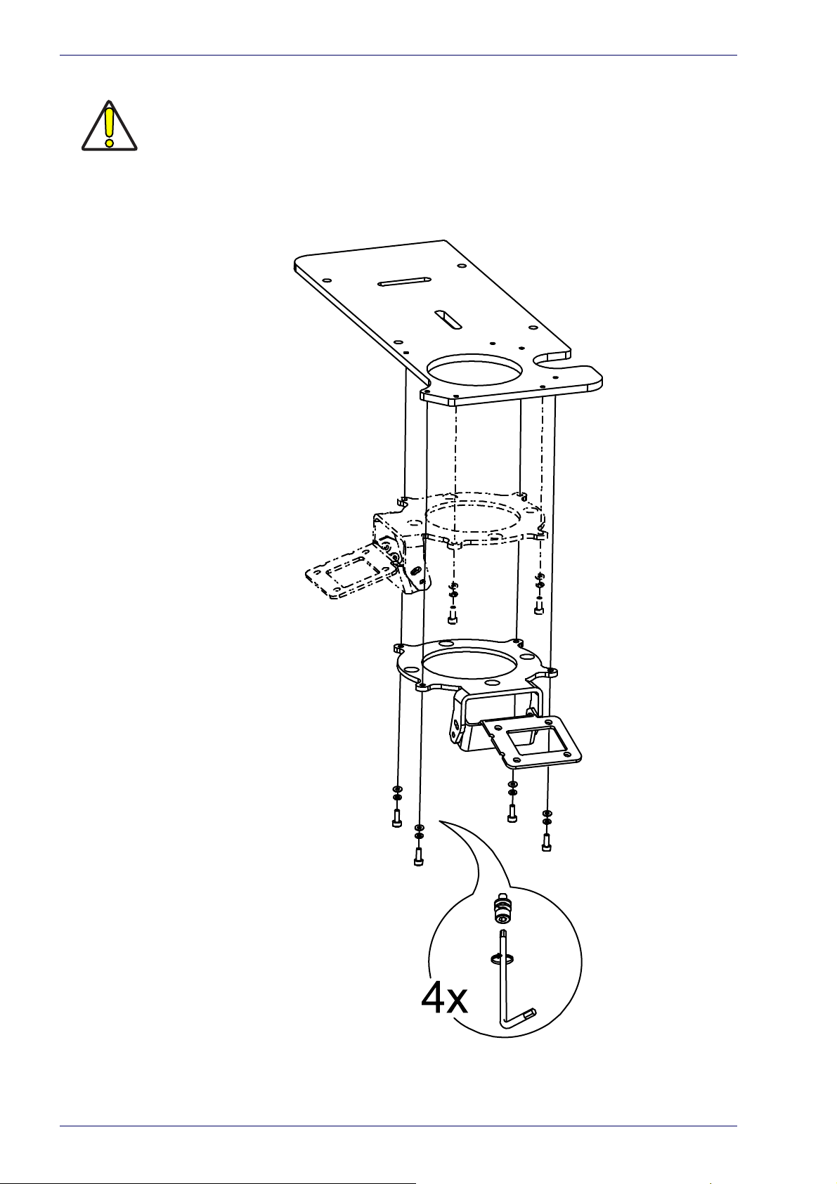
Hardware Installation
Fix the adjustment plate to the Arex™ 400 with the supplied screws as shown:
17
Figure 8: Fixing adjustment plate on Arex™ 400.
Marvis™
Page 25

Mounting Instructions for Matrix
Fix the bracket to the adjustment plate with the supplied screws.The bracket can
be installed in three different positions:
Figure 9: Bracket mounting on Arex™ 400.
Application Note 18
Page 26

Hardware Installation
Fixing the Matrix 300N™, 410N™ to the bracket
Fix the Matrix 300N™, 410N™ to the bracket with the supplied screws.
19
Figure 10: Matrix 300N™, 410N™ mounting on bracket.
Marvis™
Page 27

Fixing the Matrix 220™ to the bracket
Fix the Matrix 220™ to the bracket with the supplied screws.
Mounting Instructions for Matrix
Figure 11: Matrix 220™ mounting on bracket.
Application Note 20
Page 28

Hardware Installation
Connecting Matrix 220™, 300N™ and 410N™
This section describes the Marvis™ system wiring. Carry out the connecting
operations as described below.
Refer to the corresponding user manual of the laser marker for the main connections.
NOTE
Connect the components of the Marvis™ system together WITHOUT voltage in order to
avoid risks to th
W
ARNING
Connecting Matrix to the Ethernet
Connecting to Matrix
Connect the M12 connector of the Ethernet cable to the M12-4F connector of the
Matrix:
e operator and to the laser marker.
Figure 12: Wiring Ethernet cable to Matrix.
Connecting to Vlase™
Connect the RJ-45 connector of the Ethernet cable to the laser marker:
21
Figure 13: Wiring Ethernet cable on Vlase™.
Marvis™
Page 29

Connecting Matrix 220™, 300N™ and 410N™
Connecting to Arex™
Connect the RJ-45 connector of the Ethernet cable to the laser marker:
Figure 14: Wiring Ethernet cable on Arex™.
Connecting to UniQ™
Connect the RJ-45 connector of the Ethernet cable to the laser marker:
Figure 15: Wiring Ethernet cable on UniQ™.
Application Note 22
Page 30

Hardware Installation
Connecting to Arex™ 400
Connect the RJ-45 connector of the Ethernet cable to the laser marker:
NOTE
W
ARNING
Figure 16: Wiring Ethernet cable on Arex™ 400.
If the laser marker is to be controlled remotely, an Ethernet switch can be used for network connections.
If the “Discovery” function does not detect
the LAN and try again.
any device, disconnect other devices from
23
Marvis™
Page 31

Connecting Matrix to power supply
Connecting to Matrix
Connect the power supply cable to Matrix (via M12-17F).
Figure 17: Wiring M12-17F connector to Matrix.
Connecting to Vlase™, Arex™ and UniQ™ laser markers
Connect the power supply cable of the Matrix to power supply PG6000 (via M128F).
Connecting Matrix 220™, 300N™ and 410N™
Figure 18: Wiring M12-8F connector to PG6000.
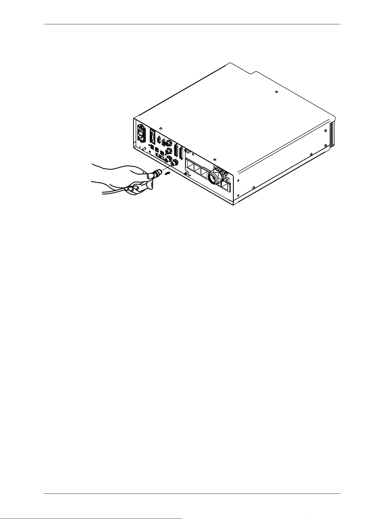
Connecting to Arex™ 400 laser marker
Connect the power supply cable of the Matrix to the Device Port 1 on the control
rack back panel:
Figure 19: Wiring M12-8F connector to the Arex™ 400 Device port 1.
Application Note 24
Page 32

Hardware Installation
Connecting LED Ring Light ID (optional)
Vlase™, Arex™ and UniQ™ laser markers
Connect the M12 connector of The LED Ring Light ID to the M12-8Y adapter on
one of the two M8-M connectors.
Figure 20: Wiring LED Ring Light ID to the adapter.
Connect the power supply cable of the Matrix to the other M8-M connector of
the M12-8Y adapter.
Figure 21: Wiring Matrix™ to the adapter.
Finally connect the PG6000 M8-8F connector to the M8-F connector on the
adapter.
25
Figure 22: Wiring PG6000 to the adapter.
Marvis™
Page 33
Connecting Matrix 220™, 300N™ and 410N™
Arex™ 400 laser marker
Connect the M12 connector of The LED Ring Light ID to the Device Port 2 on the
control rack back panel.
Figure 23Wiring LED Ring Light ID to the Arex™ 400 Device port 2.
Application Note 26
Page 34

Chapter 4
Software Configuration
HOW TO CONFIGURE YOUR MARVIS™ SYSTEM starting on page 28
HOW TO TEST, MARK AND VALIDATE YOUR DOCUMENT starting
on page 34
MARKING AND VALIDATION STAT IS TI CS starting on page 36
TROUBLESHOOTING starting on page 38
27
Marvis™
Page 35

How To Configure Your Marvis™ System
Refer to Lighter Suite software user manual for a proper use of the same.
NOTE
How To Configure Your Marvis™ System
Right-click on the Laser Engine icon in the Icon Tray and select the Laser configuration item.
In the Laser Configuration window, go to the MARVIS section and choose Discovery.
If the laser marker is to be controlled remotely, an Ethernet switc
work connections.
h can be used for net-
NOTE
Application Note 28
Page 36

Software Configuration
Select the reader to connect and press Manage Device.
Set the IP address to assign to the reader and press Change.
29
NOTE
W
ARNING
W
ARNING
The IP address to be assigned must belong to the same subnet as the laser marker.
If the “Discovery” function does not detect
the LAN and try again.
The DHCP option is to be used only for advanced users.
any device, disconnect other devices from
Marvis™
Page 37

How To Configure Your Marvis™ System
Press Test to verify the correct connection of the laser marker to the reader.
When the test is complete, press Apply and then OK to proceed with the configuration.
Start Lighter Suite, create a layer, add a code (for example a Datamatrix) and
Photometric Adjustment.
press
The features “Extended Layer” and “Ring Document” are not supported by MARVIS™
application.
W
ARNING
Application Note 30
Page 38

Software Configuration
In the new window, press Auto Setup to automatically configure the photometric
parameters of the reader.
NOTE
If the Auto setup is completed correctly the decoding is successful:
Auto Setup estimates the exposure time and gain parameters based on the luminosity
and contrast observed in the captured image but it doesn't always correspond to the
optimum results for Quality Grading. We recommend therefore to consider the Auto
Setup results as a starting point to obtain the optimum working conditions. If you don't
obtain the expected grading results from your reference samples, you should adjust
the photometry parameters manually and observe the statistical behavior of the grading until the desired results are obtained. Refer to “Help” on page 41 for more information.
In Results tabs copy (CTRL+C) the text of the decoding result and press Save to
save the parameters and continue.
31
Marvis™
Page 39

How To Configure Your Marvis™ System
Now paste (CTRL+V) the text of the decoding result in the property of the symbol and proceed with the l
Grade Training button.
earning of the quality grade by selecting the Quality
Type the acquisition number to be executed and start the learning by pressing
Start Training.
Refer to “Help” on page 41 for more information about the quality grade.
NOTE
Application Note 32
Page 40

Software Configuration
At the end of the learning the percentages and degree of reading quality will be
displayed.
Select Apply Custom Metric to apply the individual metrics learned to the project.
33
You can set a single degree of Overall desired for all metrics by selecting it in the
item Overall grade.
Marvis™
Page 41

How To Test, Mark and Validate Your Document
How To Test, Mark and Validate Your Document
You can simulate marking and validation by pressing the Send Marking button.
The result of the simulation is visible on the Lighter icon tray.
It is now possible to save the document by
pressing the Save to Device button.
Application Note 34
Page 42

Software Configuration
Open Laser Engine, select the document you just saved and perform the marking
by pressing Start marking button.
The result of the marking and validation is visible on the Laser Engine icon tray.
For automatic processing it is possible to execute a sequence. In Laser Engine
h to Auto Mode, select the sequence document and start marking by press-
switc
art marking button.
ing St
35
In the Laser Engine Documents tab, in addition to the preview of the document,
it is also possible to display the steps of the sequence.
In the Laser Engine Icon Tray, at the end of each single sequence a message
appears on the
result of the marking and validation.
Marvis™
Page 43

Marking and Validation Statistics
It is possible to consult the statistics on the marking and validation processes.
Marking and Validation Statistics
Statistics on marking processes are available in the Layouts section. The following statistics are displayed:
• OK: for the marking processes correctly performed
• ERROR: for the errors in marking processes
• STOPPED: for the marking processes s
Statistics on validation are available in the Validation se
tistics are displayed:
• MATCH: to match what is marked
• GRADE TRESHOLD: for good/bad match and good/bad grade
History: press
this button to access the results history detail.
topped by an external command
ction. The following sta-
Application Note 36
Page 44

Software Configuration
In the history window it is necessary to select the desired time period.
Start marking: set the starting time
End: s
Clear:
database and images).
When the images space and DB used space are full, the oldest data are automatically overwritten. To delete the data manually, use the clear button.
Show Match Details: this button shows the match detail (to enable this button
select the marking in the time period filed)
et the end time
this button deletes all the information of the selected period (including
Update: press this button to update the time period field (for it works, the end of
the time period must be set forward of the current time
Export Data: pre
automatic export from the drop down menu.
ss this button to export the data to a .cvs file. It is also set an
37
Marvis™
Page 45

Troubleshooting
To access the troubleshooting windows right-click on the Laser Engine icon in
the Icon Tray and select the Troubleshooting item.
Troubleshooting
•In Errors Tab errors of the Current Session or the History are displayed.
In the drop-down Level menu select the type of messages to display:
- ALL: display all messages
- ERRORS: display error messages
- WARNINGS: display warning messages
- INFO: display information messages
Application Note 38
Page 46

Software Configuration
Click on the Update button to updates (select the Live Update box for an
automatic and continuous update):
- the results of the Current Session
- the results of the History whenever the period has changed
Click on Clear button to delete data of the Current Session or select period.
Click Export button to export the data of the Current Session or select
period to a .cvs file.
•In Event Tracking Tab errors of the Current Session or the History are displayed.
NOTE
In the drop-down Level menu select the type of messages to display:
- ALL: display all messages
- ERRORS: display error messages
- WARNINGS: display warning messages
- INFO: display information messages
In the drop-down Type menu it is possible to filter one or more types of
events (Lighter, Ethernet_IP; Axis, etc…).
Only the events configured in the General panel of the Laser Configuration are displayed.
Click on the Update button to updates (select the Live Update box for an
automatic and continuous update):
- the results of the Current Session
- the results of the History whenever the period has changed
Click on Clear button to delete data of the Current Session or select period.
Click Export button to export the data of the Current Session or select
period to
a .cvs file.
39
Marvis™
Page 47

Troubleshooting
Application Note 40
Page 48

Appendix A
PHOTOMETRIC ADJUSTMENT starting on page 42
QUALITY GRADE TRAINING starting on page 45
Help
41
Marvis™
Page 49

Photometric Adjustment
Setting
Photometric adjustment manages image acquisition photometry and focusing.
For most applications, the Auto-Setup routine which automatically sets the photometry is the quickest and be
manually.
Photometric Adjustment
st solution. Otherwise these parameters can be set
Exposure Time
It defines the time during which all pixels of the CMOS image sensor synchro-
nously capture the frame. This parameter must be set according to the environmental conditions (external lighting, code c
time corresponds to a lighter image but is susceptible to blurring due to the
code movement. A shorter exposure time corresponds to a darker image.
NOTE: Th
Internal Lighting Mode parameter setting, therefore, after changes to Internal
Lighting Mode, recheck Exposure Time.
Gain
Amplifies or reduces the pixel gray level effectively increasing or decreasing the
contrast of the image.
Gain Multiplier
Multiplies the defined Gain from x2 to x10 times. If set to x1, the defined Gain is
left unchanged.
Internal Lighting
Sets the operating mode of the internal lighting system. Possible values are:
• Disabled:
• Always On:
• Power Str
NOTE: To avoid LED array overheating, for Power Strobed settings, the program
automatically limits the range of allowed values for the Exposure Time parameter. It is strongly recommended to use high lighting values for short exposure
time
e range of values and step of this parameter change according to the
the built-in LED array is turned off all the time. This option can be
useful if using an external lighting system;
the built-in LED array is turned on all the time at the lowest
power level. This option is useful if the LED-array blinking (produced by Power Strobed lighting modes and rapidly occurring reading phases) disturbs the operator.
obed: the built-in LED array is on only during the image exposure
time. Different Power Strobed lighting levels can be set.
s.
ontrast etc.). In general, a longer
Application Note 42
Page 50

Help
Results
LED Group
This parameter enables one of the two possible internal lighting system LED
groups: internal or external. The internal LED Group provides Bright Field illumination for dark absorbing backgrounds. The external LED Group provides low
gle Dark Field illumination for DPM applications or highly reflective back-
an
grounds.
Sectors
This parameter allows selecting which quadrants of the selected LED group will
be enabled.
Reading Distance
For Liquid Lens models, this parameter sets the reading distance (measured in
mm) defined as the distance from the reading window to the code surface.
In Result Table Tab the values of the reading are displayed.
43
In the Console Tab the readings of the parameters defined by the user are displayed:
Marvis™
Page 51

Photometric Adjustment
The parameters to be displayed can be selected by pressing the button Console
Configuration:
Application Note 44
Page 52

Help
Quality Grade Training
Industrial traceability
In today's industrial application DPM (direct part marking) bi-dimensional codes
like Datamatrix and QRcode have become crucial to correctly identify and automatically track part
traceability) and along the entire supply chain (external traceability) till the endof-life of the product. Laser marking is the preferred choice to enhance contrast
and to increase resolution that means larger amounts of data stored in the code.
It is obvious that the most important featu
other words, the capability to ensure fail-proof reading along the supply chain.
The Code Grading process
To ensure quantitative measurement of the code quality, specific Standards and
Technical Reports have been defined: for DPM code the verification methodology
is defined in the ISO/IEC TR 29158 (that includes the AIM DPM-1-2006 Quality
Guideline).
The scope to the ISO/IEC TR 29158
Standard is to define methodologies for the measurement of specific attributes of two-dimensional
ode symbols, defining methods
c
for evaluating and grading these
measurements and finally classify
the code into five quality classes or
grades: A, B, C; D and F.
The higher the class the higher the
reliability of the reading process, F
grade symbols are unlikely to be
read successfully in most environments.
The OVERALL quality of the code is
defined
grade within the evaluated set of
individual parameters.
To perform a reliable analysis of a
c
ode, specific measuring instru-
ments, called Certified Verifiers, are
vailable on the market. These
a
instruments embed standardized
lighting systems, lenses and certified algorithms to objectively evaluate the quality of the code,
oviding a Quality Report with
pr
quantitative information about the code properties.
Verifiers are widely used use to evaluate and certify the quality of the so called
“golden sample” or
mass production to ensure fail proof readings.
by the lowest resulting
s and components within the production process (internal
re of a code is its readability, or in
“approved quality sample” to be used as the reference in
45
Marvis™
Page 53

Quality parameters of metrics
Accordingly with ISO /IEC TR 29158 that includes the AIM DPM-1-2006, seven
quality parameters or Metrics have been defined. The knowledge of the meaning
of each quality parameter may be helpful in laser marking process tuning. Each
quality parameter is classified into grades from A to F, and OVERALL is defined
as the lowest result among all the parameters or metrics.
CC - Cell Contrast
This parameter measures the differences between the mean brightest
and the mean darkest values of the symbol.
'In laser DPM the creation of background of the code (quiet zone) with
ow power settings is extremely effective to boost the contrast.
l
CM - Cell Modulation
Cell modulation analyzes the uniformity of the contrast inside the code extension.
'In laser DPM this defect is usually refers to local non-uniformity of the material
surface (i.e.
curved marking surfaces.
finishing quality, dust, oil...) incorrect marking distance or tilted/
Quality Grade Training
FPD - Fixed Pattern Damage
This metric checks the fundamental characteristics of the
code (quiet zone around the code, “L” finder and clocking
tterns, and reference dots).
pa
Poor results on this metric may reduce the capability to
cate and read the code.
lo
As for “Cell Contrast”, the use of a smooth
reduces the risk of low grade FPD.
UEC - Unused Error Correction
Data Matrix incorporates an error correction mechanism and data
redundancy. This parameter tests and grades how much redundant
data had
fect mark that requires no error correction would achieve a UEC score
of 10
to be used during reading to decode the data content. A per-
0% that results in grade A.
PG - Print Growth
Measures the deviation of actual elements dimension from
the expected element dimension due to printing problems
.e. overprint or underprint).
(i
uniform background as a quite zone
ANU - Axial Non-Uniformity
This parameter measures and grades the modules' squareness in the
direction of each of the symbol's major axes (X-axis and Y-axis).
'In laser DPM applications this metric is typically affected by off-axis
rking (tilted surfaces vs laser marking axis) but also off- axis read-
ma
ing (skewed reader vs target surface).
MR - Minimum Reflectance
Determines the degree to which the object reflects light.
Accurate tuning of laser parameters like power, speed
matically influence this quality parameter.
Application Note 46
and repetition rate dra-
Page 54

Help
GNU - Grid Non-Uniformity (GNU)
This parameter measure and grades the module placement by comparing to a nominal evenly spaced grid.
Assuming a grid on which the ideal angle of intersection is 90°, any
angl
Verification process
A DPM verification system or Verifier is composed of an imaging sensor, optical
lens, dedicated lighting, stand and fixturing and verification software.
The verification process begins with the acqu
a standardized configuration (lighting Angle, Wavelength, and optical system
Aperture).
After a digitalization process
assesses the images on a number of quality metrics specified by the ISO/IEC
Standards.
The output of a verification process is a digital report that includes the results of
th
e quality metrics analysis and the overall grade of the code. Additional infor-
mation or customized metrics are so
This off-line process, is aimed to test output of a marking equipment to ensure
r
eliable code readability or to create the so called “Golden Sample” to be used as
a quality reference.
From a process control standpoint, DPM verification systems can quickly detect
pro
blems at the marking station by monitoring variations in the quality of a just-
applied code.
e deviation from 90° constitutes Grid Non-Uniformity.
isition of the image of the code, in
the image is evaluated by a Software Library that
metimes present in the report.
Verification in production environments
As other standard measurement instruments, Certified Verifiers are dedicated to
operate in controlled environment, and typically are not suitable to monitor code
quality in real world production environments.
Code acquisition in a real production environment is sensitive to ambient light
v
ariation, mechanical vibration, electrical noise, degradation of the LED light
system, etc. These fluctuations are not compatible with absolute and standardized measurement of the grade and cause, for example, the grade of the same
mples measured several times to actually give different values.
sa
In automatic production processes it is important to constantly monitor in-line
th
e quality of the marking in order to scrap non -readable or poorly readable
components.
For the in-line quality check of the just-applied codes,
the Datalogic Matrix 300N™, are widely used, to perform comparative analysis of
the code quality, monitoring at high speed variation in a real harsh production
environment.
Even though the Matrix family uses a gradi
standards, it does not take into consideration the external environmental lighting parameters such as Aperture, Wavelength and Illumination Angle which can
n any case affect the Scan Grade. For this reason the Matrix family can be used
i
to monitor variations in code quality but cannot be considered as a Certified
Verifier.
MARVIS™ is the traceability solution that ensures code quality in real production
vironments and combines into one single Graphical User Interface the flexibil-
en
ity of Laser Marking and the reliability of Matrix series industrial code images.
MARVIS™ allows collecting multiple measurements and computes the statistical
ersion of each individual quality parameter, measuring and considering the
disp
contribution of each individual parameter.
industrial readers, like
ng library fully compliant with ISO/IEC
47
Marvis™
Page 55

This statistical approach allows real sample quality threshold training and a sim-
Fig.1 Validation Report from certified Verifier.
Fig.2 Results of in-line quality
inspection.
ple and immediate visualization of the qua
This fully automatic Quality Training process provides a so called “QUALITY PRO-
FILE” (Patent Pending) that always includes all the relevant quality parameters.
In-line validation: a real example
To fully understand the advantages of this approach, consider the following
example.
An OEM car manufacturer orders from a Tier1 supplier a mechanical component
hat includes a Datamatrix code.
t
To ensure reliable internal traceability, the OEM requires a QUALITY GRADE B or
tter.
be
The Tier1 manufacturer, produces a batch of
samples a
requirements, and, to evaluate the Quality Grade
o
f the 2D code, he refers to a Certified Verifier
that in the Metrologic laboratory provides a
quality report as GRADE B, fully compliant with
OEM request (Fig.1)
To ensure contract compliance, and reduce the
cost of r
Tier1 manufacturer decides to incorporate a
direct part mark reader to monitor the DPM code
quality.
ccordingly
ejecting parts due to unreadable codes,
with the customer's
Quality Grade Training
lity spread for each code parameter.
Once installed in a real production environment
beside the laser marking un
mark reader provides an overall GRADE C, even
on the same “golden sample” just certified as
GRADE B. (Fig.2)
How do they correlate these two pieces of information?
It is clear that the “golden sample” has an intrinsic quality of GRADE A, as validated by the Certifie
On the other side, the in-line code reader is really affected by measurement
e
rrors caused by installation factors like tilt, skew, not optimal reading and
lighting etc.
These errors are always present in real world environments and are usually
ated to the effectiveness of the embedded grading algorithm.
rel
d Verifier.
it, the direct part
Application Note 48
Page 56

Help
MARVIS™ advantages: training on real sample
Starting from a qualified “golden sample”, MARVIS can provide a QUALITY PROFILE (Patent Pending) that maps quality distribu
the case of non-ideal installations and environment.
This Quality Profile defines a threshold metric by metric mitigating influence of
ext
ernal factors.
Setting a Quality Profile is as simple as pressing the “START
tion on each single metric even in
TRAINING” button.
MARVIS™ advantages: single metric quality grade analysis
The use of OVERALL GRADE to validate the code quality may not detect some relevant code quality degradation.
By definition, code verification is based on
sample parts with a reference grade. Since Overall Code Grade is determined
only by the lowest grade among all the metric parameters, any fluctuation in
individual metrics that lies above the lowest grade is neglected.
In other words, verification on OVERALL GRADE = C will
single metrics between A and C.
In the following example, three samples
erified with a target quality of
are v
GRADE C.
Since for all samples the lowest grade
within the selected metrics is “C”, the
OVERALL grade of the three samples
match the requirements and all samples
are verified and validated.
Instead, a single metric analysis, shows
that the three samples are quite different.
Sample #3 has a much lower quality on
4
parameters (CM, UEC, MR, GNU) compared to other samples and to the refer-
ence.
These differences are “masked” by the poor results on Axial Non Uniformity of
the ref
erence that contribute to the OVERALL GRADE.
matching the OVERALL GRADE of the
ignore any variation on
Thanks to the QUALITY METRIC
GRADE PROFILE, MARVIS™ is able to
luate the fluctuation in quality
eva
on single metrics, independently
from the OVERALL, ensuring high
read rate along the entire supply
chain.
49
Marvis™
Page 57

MARVIS™ advantages: statistic threshold
GRADE PROFILE offers also a clear indication of the statistical threshold of a
quality grade for each metric.
In the following table it is evident that FPD for a specific sample will be GRADE B
at 65%
This statistical approach
pr
view of the distribution of
the quality.
By running CODE QUALITY
TRAINING on different
lighting conditions, it is
possible to evaluate the
influence of the external
environment on the grading analysis, and eventually compensate for
fluc
Marvis™ suggest GRADE C
(i
an excessive scrap rate. Selecting the GRADE B threshold for this metric would
statistically result in a 35% scrap rate.
and GRADE C at 35%.
ovides an immediate
tuations.
n green) for FDP to avoid
Quality Grade Training
Application Note 50
Page 58

Appendix B
GENERAL SPECIFICATION starting on page 52
IEC62471-1 COMPLIANCE starting on page 52
About LED Ring Light ID
51
Marvis™
Page 59

General Specification
General Specification
Electrical Specifications
Operating Temperature
Cable Informations 3 meters (118”) long
Compliance
IP Rating IP50
Lumen Maintenance
Working Distance
Optical Performances
Color 24V Current (A)
WHI 0.14 0.47
0° to 60° C
CE, RoHS
L70 = 50,000 hours
Illuminance
(mm)
100 46.0 136.0
300 10.8 31.4 190.5
600 3.8 8.6 355.6
(klux)
Irradiance
(W/m2)
Electrical specifications
FWHM Diameter
(mm)
114.3
IEC62471-1 Compliance
This product has been classified RISK GROUP 1 (LOW-RISK) according IEC62471-
1.
The philosophical basis for this classification is that the lamp does not pose haz-
ard due to normal behavioral limitations on exposure. This requirement is met
by lamp that
• a retinal blue-light hazard (Lb) within 100s, nor
• a retinal thermal hazard (Lr) within 10s
Only Lb and Lr are considered because the product uses white LEDs (emissions
ly in the 400-780nm range).
on
In carrying out the obligations laid down in Articles 6(3) and 9(1) of Directive 89/
1/EEC, the employer, in the case of workers exposed to artificial sources of
39
optical radiation, shall assess and, if necessary, measure and/or calculate the
levels of exposure to optical radiation to which workers are likely to be exposed
so that the measures needed to restrict exposure to the applicable limits can be
identified and put into effect. (article 4, section II, Directive 2006/25/EC of the
European Parliament and of the Council of 5 April 2006 on the minimum health
and safety requirements regarding the exposure of workers to risks arising from
physical agents (artificial optical radiation).
exceeds the limits for the Exempt Group but that does not pose.
Application Note 52
Page 60

© 2018-2019 Datalogic S.p.A. and /or its affiliates • All rights reserved. • Without
limiting the rights under copyright, no part of this documentation may be reproduced,
stored in or introduced into a retrieval system, or transmitted in any form or by any
means, or for any purpose, without the express written permission of Datalogic S.p.A.
and/or its affiliates • Datalogic and the Datalogic logo are registered trademarks of
Datalogic S.p.A. in many countries, including the U.S. and the E.U.
www.datalogic.com
Datalogic S.r.l.
Via S. Vitalino, 13 | 40012 Calderara di Reno | Bologna - Italy
Tel. +39 051 3147011 | Fax +39 051 3147205
 Loading...