

Page 1
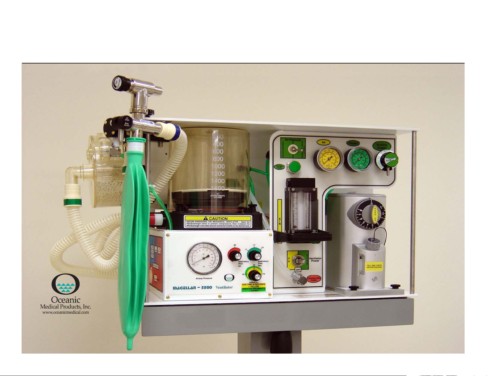
Magellan-2200 Model 1 Anesthesia Machine Operators Manual
8005 Shannon Industrial Park Lane
Atchison, Kansas 66002
Tel: 913 874 2000
Fax: 913 874 2005
oceanicmedical@lvnworth.com
Version: 040505
Page 2

TABLE OF CONTENTS PAGE
SUBJECT
• General Description 3
• Definition of Statements 3
• General Warnings 3
• Machine Specifications 3
• Functional and Operational Procedures 5
Assembly of Components 6
Pre-Use Checklist 10
Operation of Controls and Accessories 15
Post-Use Checklist 20
• Cleaning, Disinfecting and Sterilization 21
2
• Minor Maintenance Recommendations 21
Tools Needed for Maintenance 21
Cylinder Gas Duration Formula 24
Gas Flow Diagrams 25
• Items Furnished with Each Machine and Part Numbers 30
•Additional Items Needed for Operation and Maintenance 32
• Bill of Materials with Part Numbers 33
•Exploded View Diagrams of Major Components 35
Page 3

GENERAL DESCRIPTION
The Magellan-2200 Anesthesia Machine is compact robust and flexible, easy to transport
and was designed for military forward surgical teams, combat surgical hospitals, general
civilian hospitals, outpatient surgical centers, office-based anesthesia, military and civilian
veterinary medicine.
The Magellan-2200 is completely pneumatically powered and is designed to be used with
any complete or simple patient monitoring system that the operator prefers to use or has
on hand.
The Magellan-2200 may be mounted on its custom-made carrying case, a mobile trolley
especially designed for the unit, other mobile carts or on a tabletop as the operator prefers.
3
3. Ventilator Power Source-Ensure that adequate Oxygen or Compressed Medical Air
pressure and volumes are available before engaging the ventilator power toggle switch to
ensure proper operation of the ventilator.
MACHINE SPECIFICATIONS
DIMENSIONS
Height 23 inches
Depth 23 inches
Width 17 inches
Factory Quality Assurance Testing
Each Magellan-2200 is tested several times during the manufacturing process. Final testing
and calibration of components and the completed machine are recorded and a final
functional test copy is included in the shipment from the factory to the initial customer.
DEFINITION OF STATEMENTS
The following terminology and statements are important for the operator to understand
before proceeding with the manual or operation of the Magellan-2200:
WARNINGS: indicate a possibility of injury to the operator or others
CAUTIONS: indicate a possibility of damage to the equipment
NOTES: indicate points of interest for proper operation of the equipment
General Warnings:
1. Patients requiring life-support equipment should be under the constant surveillance of
competent medical practitioners. There is always the possibility of machine and alarm
failure and some malfunctions require immediate, corrective action.
2. Vaporizer-Tilting the vaporizer past 45 degrees with liquid agent in the chamber can
result in patient injury or death. If tilted past 45degrees, empty the chamber, fully open the
percent control, then flush the vaporizer with Oxygen from the Oxygen flowmeter set to
5 lpm for 10 minutes.
Wei ght
• Free-Standing 45 lbs
• Enclosed in Carrying Case 100 lbs
Machine Materials Aluminum, brass and plastic
Carrying Case Materials Plastic, military grade
Operating Temperature Range 35 degrees F to 110 degrees F
Required Gas Supply Sources
• O2 Main and Cylinders 38 to 70 psi (50 psi is optimal)
• Air and/or Air Compressor 38 to 70 psi (50 psi is optimal)
• Oxygen Concentrator 3 to 10 psi (For O2 Flowmeter only)
Flowmeter Fresh Gas Flow 1 to above 20 lpm (each flowmeter)
Oxygen Flush Valve Recessed, self-closing, push-button, color coded and
labeled, provides 45-55 lpm constant flow, while
push-button is depressed; may not be used with
O2 concentrator as O2 power source
CO2 Absorber System King Systems KAB-9 (re-fillable) or KAB-1
(pre-filled/disposable)
CO2 Absorber Canister Capacity 400 grams soda lime
Directional Valves Built in the CO2 Absorber
Page 4

CO2 Absorber Holding Bracket Plastic, secured with knob to main frame of machine
Bag-Ventilator Switch/PRV Hand-operated selector switch and rotating knob for PRV
and Scavenger Outlet Port and scavenging outlet
Bellows Latex free, upward inflating, range from 0 to 1.6 L
Bellows Pressure Relief Pre-set at 60 cmH2O
4
Auxiliary O2 Flow Selector Scaled 0-10 LPM in set increments, used for pre/post
anesthesia
Vap ori zer Penlon SigmaDelta Series, bolt (cage) mounted,
temperature compensated, very low maintenance
Airway Pressure Gauge Dual scaled in cmH2O and mmHg, located on front
panel of ventilator
Common Gas Outlet Quick-connect, size indexed
Tubing Circuit King Systems F-360-61 or any standard anesthesia
circle circuit
Gas Pressure Hoses DISS and thread indexed, female connectors at both ends
Gas Inlet Manifold DISS and thread indexed, male connectors with one-way valves
Gas Inlet Manifold Filters Located behind Manifold Air and O2 inlet male connectors
Gas Inlet Pressure Regulators
• Main supply cylinder
• Safety back up cylinder Pin-indexed, yoke mounted for "D" and "E" cylinders for O2
Oxygen and Air Supply Gauges 0-3000 psi range, color coded and clearly labeled
Oxygen Supply Alarms
DISS/thread indexed for O2
• Main and safety back-up Pneumatically actuated when O2 supply falls below 30 psi
• O2 Concentrator Pneumatically actuated when O2 supply falls below 1 psi
• Alarm power source 9-volt battery located in body of alarm box
• Alarm on/off Labeled toggle switch located on body of alarm box
Air and O2 Flowmeters Calibrated and scaled 0-10 lpm, color coded, O2 flowmeter
has a fluted control knob for easy identification by touch,
alone
Oxygen Concentrator To power O2 flowmeter only
Air Compressor May be used to power ventilator and air flowmeter
Pressure Gauge Tubing May be attached to bag/vent switch arm or to a point
within the patient breathing circuit (operators choice).
Mechanical Ventilator Pneumatically powered, time cycled, volume constant,
flow variable
• Ventilator Pressure Relief Pre-set to maximum of 60 cmH2O located in main vent box
• Volume Range 0 to 1.6 L
• Insp. Flow Range 0 to .90 lps
• Insp. Time Range 0.2 to 3.0 seconds
• Exp. Time Range 0.2 to 30 seconds
• Pressure Relief Valve Preset to 60 cmH2O
Ventilator Gas Power 40 to 70 psi, 50 psi optimal
Requirements Use toggle switch to select gas source
Waste Gas Scavenger Positive and negative relief valves, 1 L reservoir bag,
vacuum control knob
Total Machine Gas Leakage @ 30 cmH2O -0- ml/Min
@ 80 cmH2O -0- ml/min
Internal System Compliance @ 20 cmH2O 1.1 ml/cmH2O
@ 40 cmH2O 1.3 ml/cmH2O
Internal System Resistance @ 1.0 L/sec gas flow 4.11 cmH2O
@ 0.5 L/sec gas flow 1.80 cmH2O
APL Valve Pressure Drop @ 3.0 L/min gas flow 0.12 cmH2O
@ 30 L/min gas flow 1.03 cmH2O
Oxygen Analyzer/Monitor OM-25-ME (or equivalent) Galvanic cell sensor, life
expectancy 2 years under normal conditions
Oxygen Analyzer Power Source 2 each AA batteries, life expectancy approx. 3000 use hours
Storage
• Indoor
• Outdoor - 30°FOR temp for 1hour
+ 160°FAllow unit to warm to normal
Page 5
FUNCTIONAL AND OPERATIONAL PROCEDURES
The following procedures should be performed between the time the Magellan-2200 is
assembled for use, actually used and post-use, to ensure proper assembly of components
and operation.
5
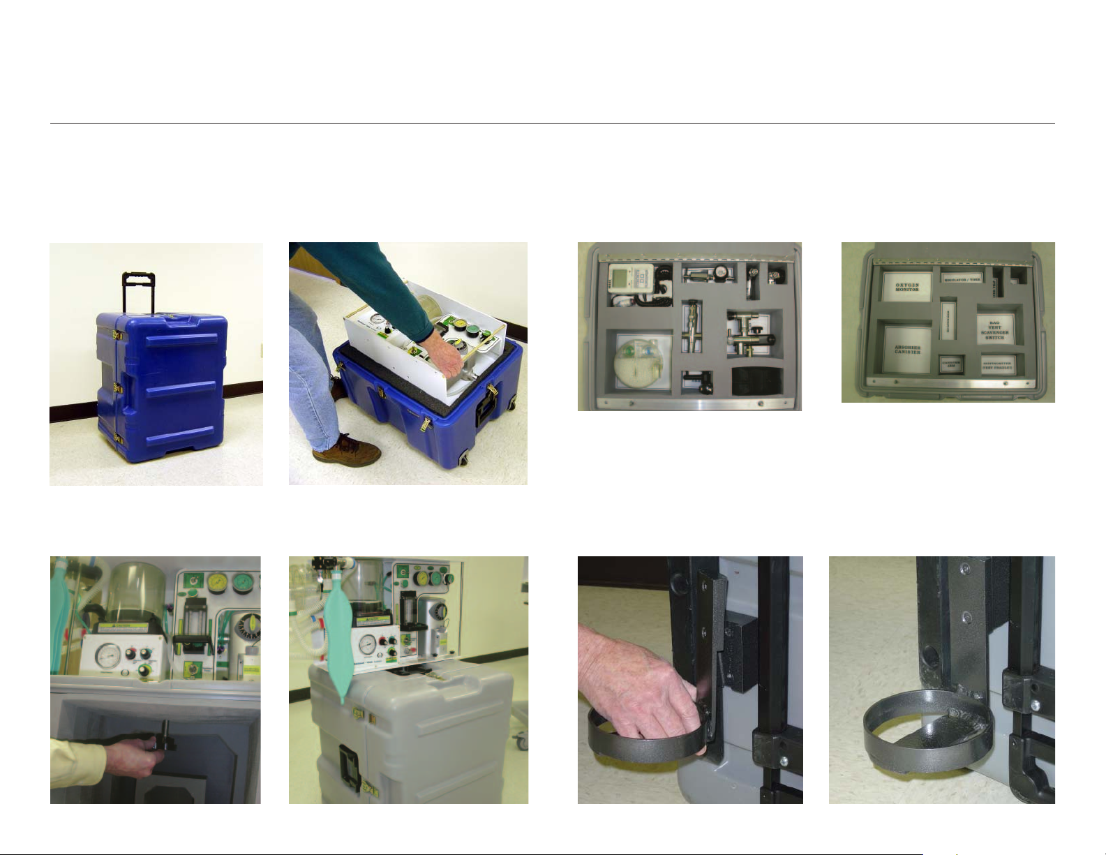
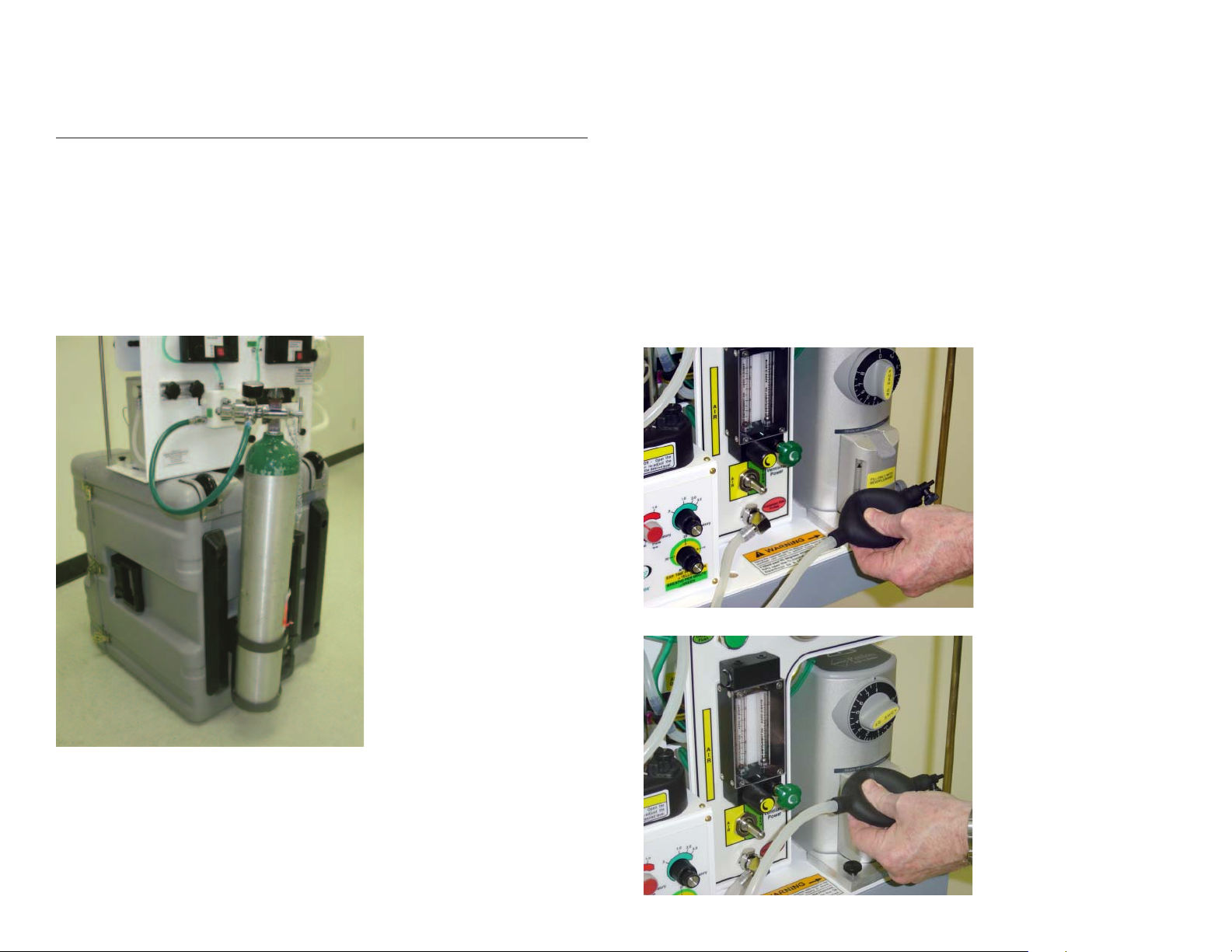
1. Removal and Mounting of Machine
Turn on side, open, remove lid
5. Mount anesthesia machine to top of
box, securing with mounting screws.
2. Remove machine; Turn open box so that
wheels are down.
6. Reattach lid of box to front of box with
machine mounted.
3. Review parts in lid of ventilator box.
7. Attach small O2 cylinder mount to box back.
4. Positioning of parts in lid of ventilator box.
8. O2 cylinder mount completely attached.
Page 6
ASSEMBLY OF COMPONENTS FOR USE OF THE MACHINE
BACK OF MACHINE
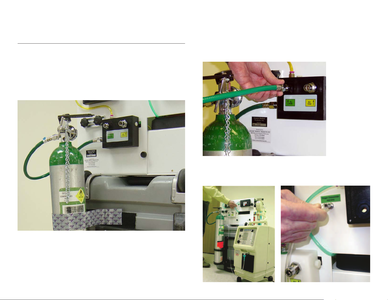
1. Pressure Reducing Regulator:
Attach yoke-type pressure reducing regulator to the "D" or "E" Oxygen cylinder to be used
for safety back-up purposes.
2. Oxygen Hose:
Attach one end of the 24" green O2 high pressure hose to the outlet port of the pressure
reducing regulator and the opposite end to the left-side of the Gas Manifold.
6
3. Oxygen Hose: Main O2 Supply:
Attach one end of the 15' green O2 high pressure hose to the top left O2 inlet connector
on the Gas Manifold and the opposite end to the O2 source (either an O2 Cylinder or
O2 Wall outlet.)
4. Oxygen Concentrator in Lieu of Main O2 Source:
If an O2 Concentrator is to be used instead of cylinder or wall O2 sources, the tubing from
the O2 concentrator should be connected to the specially labeled (O2 concentrator only)
inlet nipple located above and to the right side of the Gas Manifold.
Page 7
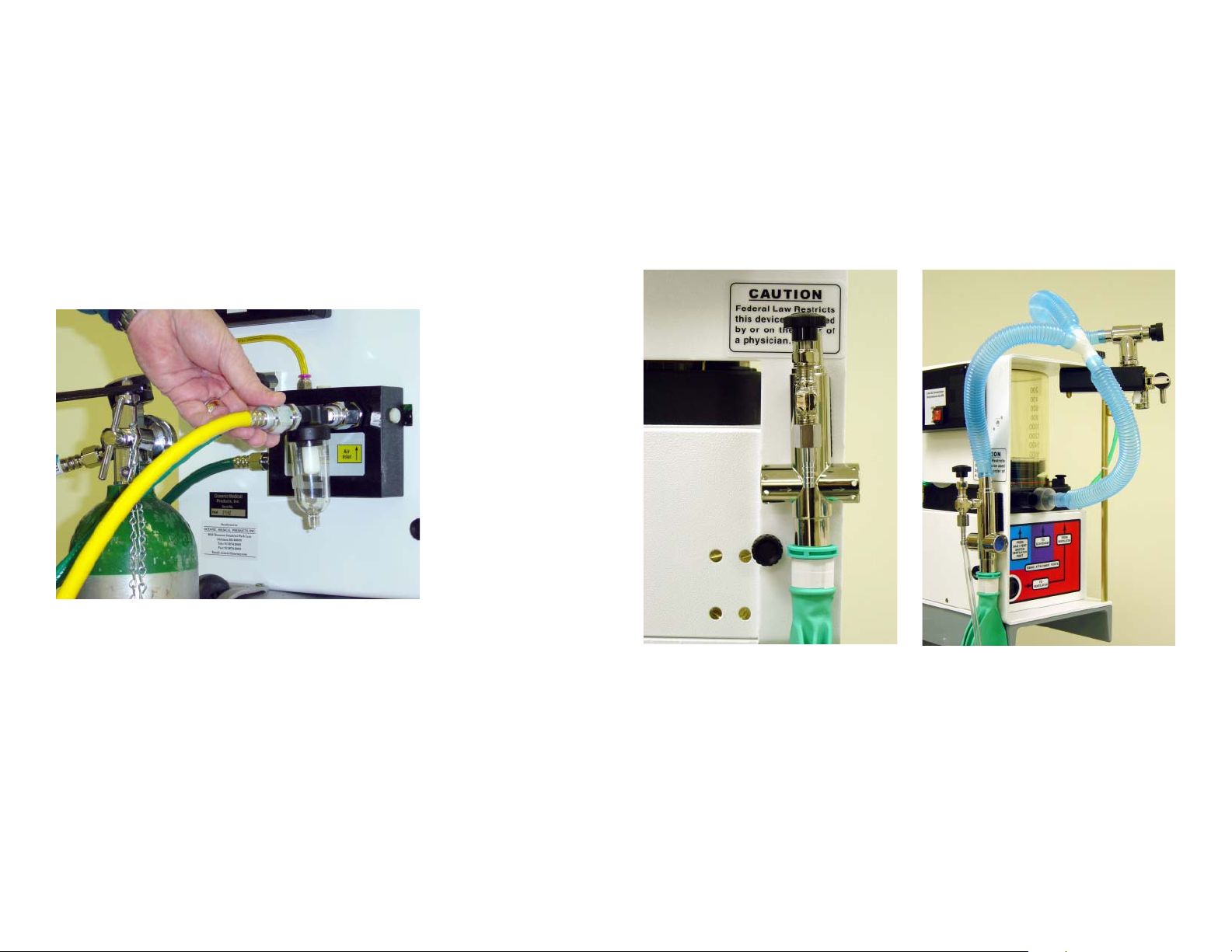
5. Water Trap:
Attach the Water Trap to the Air inlet port on the GasManifold
CAUTION: Do not attach the water trap to the outlet port of the Air Compressor as water may
condense enroute to the anesthesia machine and cause possible malfunction of some of the
components.
6. Air Hose:
Attach one end of the 15' yellow Air high-pressure hose to the inlet port of the Water Trap.
Attach the opposite end of the high pressure hose to the air compressor outlet port or to
other Air sources (wall or cylinder)
7
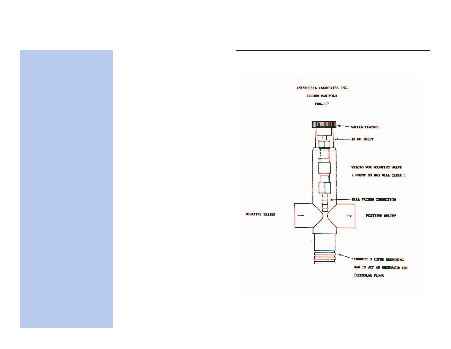
7. Waste Gas Scavenger Tubing Connection:
1. Attach the waste gas scavenger to the upper right hand side of the back frame, using the
Velcro strip or keyhole mounting, then attach the reservoir bag to bottom port of the
scavenger. Attach suction source tubing to the inlet port of scavenger control knob port.
NOTE: In military field conditions the reservoir bag to the bottom port of the scavenger
may be replaced with a large bore hose to possibly evacuate waste anesthetic out of the
work area.
.
WARNING: Scavenger system should always be mounted in order to keep debris from
entering the bellows outlet port.
1. Attach one end of the first scavenger tubing to the scavenger outlet port of the B/V
Switch labeled "to scavenger" and the opposite end to the "TEE" connector.
2. Attach one scavenger tubing, with the 19mm purple connector to the center port located
on the base of the Bellows, and attach the other end to the "TEE" connector.
3. Attach the final scavenger tubing to the top of the Waste Gas Scavenger and the other
end to the "TEE" connector.
Page 8
VENTILATOR SIDE OF MACHINE
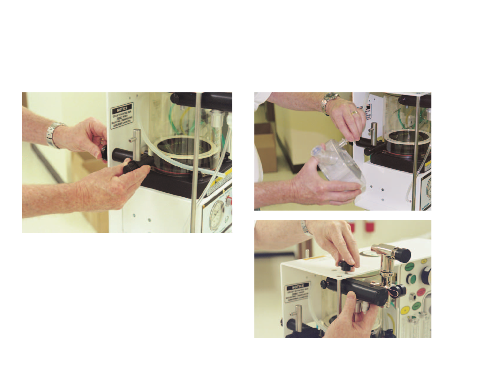
1. CO2 Absorber Support Arm:
Attach the CO2 Absorber Support Arm to the Main body of the machine by inserting the two
pins of the Arm into the two holes provided-then screw in the knob-screw from the back side
of the frame to secure the Arm. Ensure that the stem of the Arm is pointed upwards.
8
2. Bag-Vent Switch Assembly Arm:
Attach the Bag/Vent Switch Assembly Arm to the top of the machine, using the dowel pin guide
located under the top of the machine and insert the B/V Switch hole provided for the dowel pin.
Secure the B/V Switch by inserting the knob-screw through the top of the machine.
Page 9
3. Reservoir Bag:
Attach the Reservoir bag to the chrome inlet port connector
located on the bottom of the B/V Switch Arm.
9
4. Airway Pressure Gauge Tubing:
Attach the Airway Pressure Gauge Tubing connector to the bottom of the B/V Switch Arm.
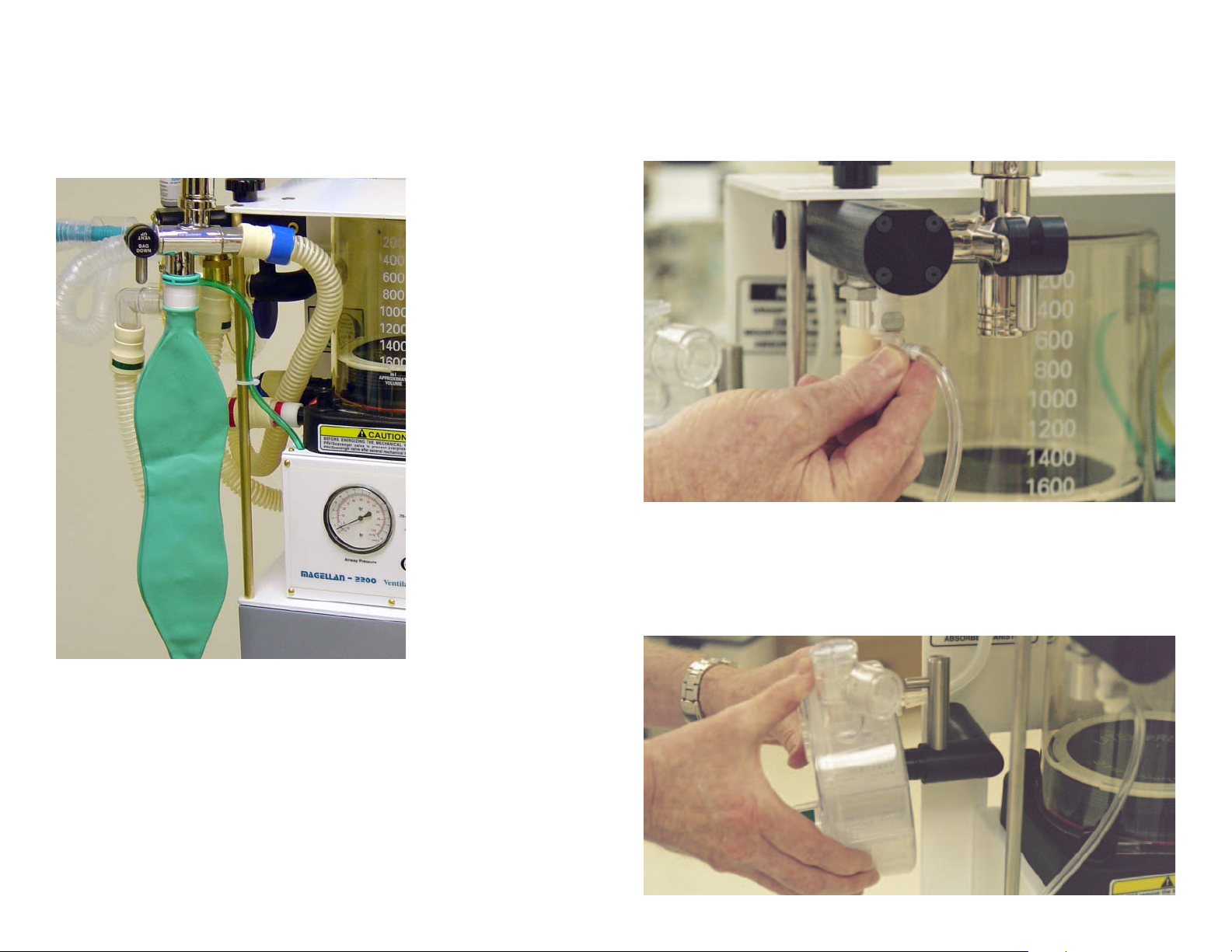
5. Gas Flow Tubing:
Attach the semi-clear tubing from the Common Gas Outlet to the inlet connector of the
CO2 absorber.
NOTE: If the clear plastic connector (supplied with the CO2 canister is not available, the
semi-clear tubing may be directly attached to the inlet port nipple of the CO2 canister.
Page 10
6. CO2 Absorber Canister:
Attach the CO2 Absorber Canister to the Absorber Support Arm.
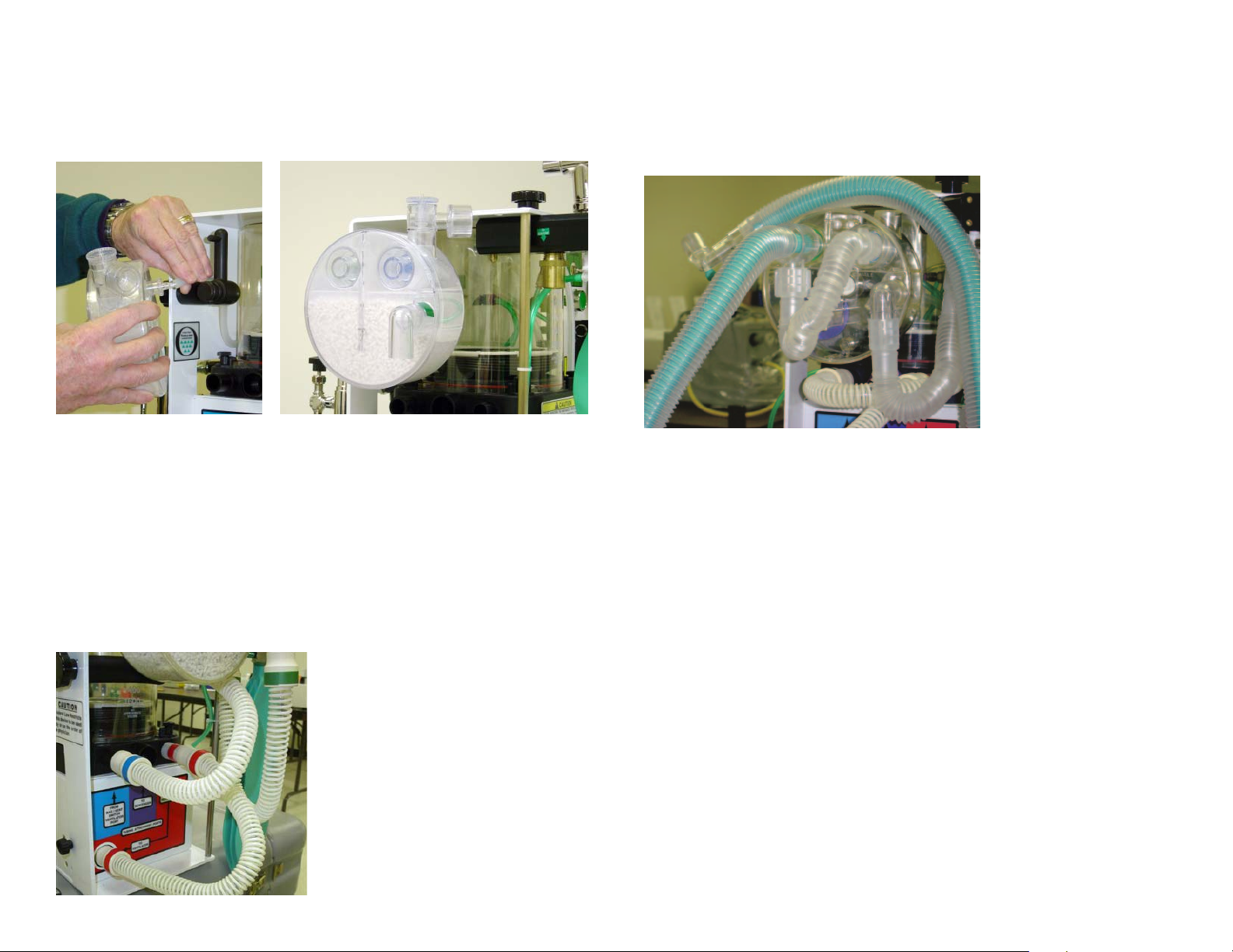
TUBING
7. Attach the RED labeled tubing to the outlet of the ventilator as shown on the label. Then
attach the other end of the tubing to the ventilator inlet port of the bellows (far right port)
using the 17mm connector.
8. Attach the GREEN labeled tubing to the brass outlet port of the B/V Switch and the
opposite end to the bottom right connector ("L" shaped) located on the bottom-right
position of the CO2Absorber.
10
10. Patient Tubing Circuit:
Attach the preferred Patient Tubing Circuit to the CO2 Absorber inlet and outlet
connecting points.
NOTE: Any patient tubing circuit approved for use with an anesthesia machine may be
used. The factory supplies a King Systems F-360-61 circuit with each machine as it is initially
shipped.
9. Attach the BLUE labeled tubing to the right side inlet port of the
Bellows (labeled blue) and the opposite end to the lower outlet port of the
B/V Switch (labeled "To Bellows").
Page 11
FRONT AND TOP OF ANESTHESIA MACHINE
11
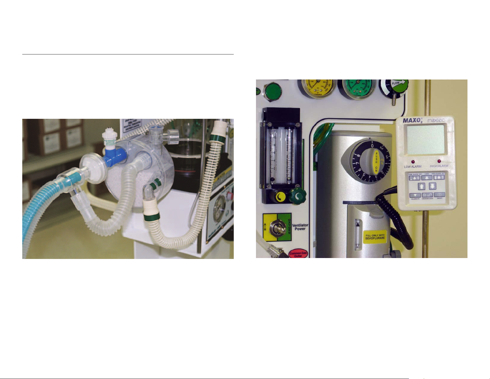
OXYGEN MONITOR ATTACHMENTS
1. Attach the O2 monitor-mounting bracket to the right side support post. Insert the monitor
into the slide bracket.
2. Attach the blue O2 monitor sensor bracket into the Inspiratory outlet located on the
left-hand side of the front of the CO2 absorber.
3. Attach the O2 monitor O2 sensor into the blue O2 sensor bracket.
CAUTION: Insure that the O2 monitor sensor is mounted into the sensor bracket facing upward
for best performance and to keep any humidity from accumulating around the sensor.
Page 12
PRE-USE CHECKLIST
12
Low Pressure System
Emergency Ventilation Equipment
1. Verify backup ventilation equipment is available and functioning. It is recommended that
a self-inflating bag/valve/mask device with the ability to provide high concentrations of O2
be immediately available.
High Pressure System
2. Check Oxygen Cylinder Supply
A. Open O2 cylinder and verify at least half full (approx. 1000 psi).
B. Close cylinder
4. Check Initial Status of Low Pressure System
A. Close flow control valves and turn vaporizer off.
B. Check fill level and tighten vaporizer filler cap.
5. Perform Leak Check of Machine Low Pressure System
A. Verify that the machine flow control valves are OFF.
B. Attach "Suction Bulb" to common gas outlet.
C. Squeeze bulb repeatedly until fully collapsed.
D. Verify bulb stays fully collapsed for at least 5 seconds.
E. Open vaporizer and repeat "C" and "D" above.
F. Remove suction bulb and reconnect fresh gas hose.
3. Check Central Pipeline Supplies
A. Check that hoses are connected and pipeline gauges read approx. 50 psi.
6. Turn on Ventilation/Ventilator Alarm
7. Test Flowmeters
Page 13

A. Adjust flow of Oxygen and Air through their full range, checking for smooth operation of
floats and undamaged flowtubes.
Scavenging System
8. Adjust and Check Scavenging System
A. Attach hose from bag-vent switch scavenger outlet to scavenger inlet.
B. Attach reservoir bag to scavenger connection port.
C. Attach suction source to suction inlet connection port.
D. Adjust suction on and ensure bag collapses.
E. Turn suction off.
13
Breathing System
9. Calibrate Oxygen Monitor
A. Ensure monitor reads 21% in room air.
B. Verify low oxygen alarm is enabled and functioning
C. Re-install sensor in circuit and flush breathing system with Oxygen.
D. Verify that monitor now reads greater than 90%.
10. Check Initial Status of Breathing System
A. Set selector switch to "bag" mode. (See photo)
B. Check that the breathing circuit is complete, undamaged and unobstructed.
C. Verify that CO2 absorbent is adequate.
D. Install breathing circuit accessory equipment (e.g. humidifier and filter) to be used
during the case.
Page 14

11. Perform Leak Check of the Breathing System
A. Set all gas flows to zero (or minimum).
B. Close PRV valve and occlude "Y" piece or install a reservoir bag to distal end of circuit.
C. Pressurize breathing system to about 30 cmH2O with O2 Flush.
D. Ensure that pressure remains fixed for at least 10 seconds.
E. Open PRV valve and ensure that pressure decreases.
14
J. Exercise breathing circuit accessories to ensure proper function.
K. Turn ventilator gas power switch to the "OFF" position and turn bag switch to
"BAG" mode.
L. Ventilate bag manually and assure inflation and deflation of artificial lung and
appropriate feel of system resistance and compliance.
M. Remove second bag from "Y" piece.
N. Turn B/V switch to "Vent". Allow bellows to fill.
O. Set Inspiratory flow to .8 lps, inspiratory time to 1 second and expiratory time to
6 seconds.
P. Utilize a 1 liter breathing bag as a test lung.
Q. Turn on the ventilator to either air or O2 depending on which gas you will be using to
drive the vent. Adjust the inspiratory time to deliver a tidal volume of exactly 800 ml.
(This adjustment will compensate for slight variations in delivery pressure from high
pressure sources.)
R. When making further adjustments in ventilating specific patients, one simple and
reliable procedure is to adjust the tidal volume by making changes in the inspiratory
flow rate and changes in respiratory rate by adjusting the expiratory time.
Manual and Automatic Ventilation Systems
12. Test Ventilation Systems and Unidirectional Valves
A. Place a second breathing bag on "Y" piece.
B. Set appropriate ventilator parameters for next patient.
C. Switch to automatic ventilation (ventilator) mode.
D. Fill bellows and breathing bag with O2 Flush. Turn ventilator power switch to air or O2.
E. Set O2 flow to minimum, Air to zero.
F. Verify that during inspiration, bellows deliver appropriate tidal volume and that during
expiration, bellows fills completely.
G. Set fresh gas flow to approx. 5 L/min.
H. Verify that the ventilator bellows and simulated lungs fill and empty approximately
without sustained pressure at end-expiration.
I. Check for proper action of unidirectional valves located in CO2 canister.
Page 15

Monitors
15
FUNCTIONAL OPERATION OF CONTROLS AND ACCESSORIES
13. Check, Calibrate and/or Set Alarm Limits of All Monitors
A. Ventilator and ventilation monitor parameters including Oxygen analyzer.
B. Physiologic monitor that may include vaporizer agent, capnometer and
pulse oximeter.
Final Position
14. Check Final Status of Machine
A. Vaporizer off.
B. PRV valve open.
C. Selector switch to BAG
D. All flowmeters to zero
E. Patient suction device available
F. Breathing system ready to use
With the Pre-Use Checklist completed, the Magellan-2200 is ready to use. It is imperative
that the operator understands how to utilize the controls of the machine properly and the
following information will be helpful:
Center "L" Frame Controls and Gauges
4
5
6
7
8
3
2
1
1. Auxiliary O2 Flow Selector: Designed to allow the operator to supply oxygen to a
patient pre and post-op with small bore tubing for a nasal cannula or disposable oxygen
mask. The selector knob will allow the operator to provide oxygen flow at 2,4,6,10 and 15
liters per minute.
Note: When not in actual use, the O2 flow selector control knob should be kept in the
"OFF" position as to not waste oxygen sources.
2. Oxygen Pressure Gauge: Indicates the source pressure of oxygen for all oxygen-related
components of the machine.
3. Air Pressure Gauge: Indicates the source pressure of compressed air for all air-related
components of the machine.
4. Oxygen Pressure Toggle Switch: This switch allows the operator to select which
oxygen source is being used; either high pressure (from a cylinder or mains) or very low
pressure from an oxygen concentrator.
Page 16

NOTE: When using high pressure oxygen sources, all of the functional oxygen controls may be
utilized, e.g. auxiliary oxygen selector, oxygen flowmeter, oxygen flush valve, and oxygen
selector to power the ventilator.
NOTE: When using an oxygen concentrator as an oxygen source, there is ONLY enough
oxygen pressure to power the oxygen flowmeter. No other oxygen-powered/related systems
will be able to function. The O2 flush will be powered by the backup "D" or "E" oxygen cylinder
when the low pressure O2 concentrator is selected for use.
16
8. Common Gas Outlet: Provides a channel for all low flow gas and vapor to flow to the
inspiratory side of the CO2 Absorber and then on to the patient and the rest of the circle system.
NOTE: An adapter is available to insert into the CGO in order that the operator may use
either a Jackson-Reese or Mapleson "D" system.
Vaporizer Mounting and General Use
1. Dismounting:
WARNING: If the O2 flush button is depressed when using an O2 concentrator, the flush
valve will exhaust the oxygen concentrator reservoir for at least 10 seconds or longer. Be
certain that the backup O2 cylinder is turned on.
WARNING: If the oxygen concentrator is employed and the operator desires to utilize the
mechanical ventilator, compressed air is the only power source that can energize the ventilator for operation. Once high-pressure oxygen is again available, the O2 pressure toggle switch
can be returned to the high-pressure position and all O2-related systems will
then operate normally.
5. Flush Button: Press the button inwards to activate 100 % oxygen through the system.
When activated, the oxygen gas flows from the flush button to the Common Gas Outlet and
thence directly to the inspiratory side of the patient tubing circuit.
NOTE: One way valves prevent the oxygen flow from the Flush Button from mixing with other
gases and vapors already in use from the flowmeters and vaporizer.
6. Flowmeters: The oxygen and air flowmeters are operated by turning the control knobs
clock-wise for decreased flow and counter-clockwise for increased flow.
NOTE: Titration of FIO2 is managed by using both flowmeters and adjusting them until the
desired FIO2 is observed on the O2 monitor read-out.
7. Ventilator Power Selector Switch: This toggle has three positions:
A. Center-OFF
B. Right-Oxygen
C. Left-Air
A.Remove the two holding knob-screws holding the retainer plate located on the
bottom-front of the vaporizer. Then remove the retainer plate.
B. Remove the two holding knobs and spacer plate from the back plate located on the
backside of the frame behind the vaporizer.
NOTE: Selection of gas power from the Air Compressor (if available) will allow O2 sources to
be conserved.
WARNING: Use only "Medical Grade Air Compressors" to power the Magellan-2200 air
systems. Non-Medical Grade air compressor-output may include oil which can cause
physiologic problems for the Patient and could result in a combustible O2-oil mixture or,
damage the equipment beyond reasonable repair.
Page 17

C. Pull the vaporizer forward and remove the inlet and outlet tubing connectors.
2. Mounting:
A. Reverse the preceding instructions.
CAUTION: After re-mounting the vaporizer, be certain that all four of the retaining knobs are
very secure in order to keep the vaporizer from moving during any transport or movement.
17
4. Raise the bottle above the filler.
5. Open the filler control latch.
6. Fill the chamber by observing the "fill" chamber window.
7. Close filler control latch.
8. Lower bottle below the level of the filler.
9. Loosen clamp screw and remove the key adapter.
10. Insert the clamp screw and tighten clamp screw.
C. Use During Procedure:
A. Turn percent control knob to desired position.
B. Adjust percent control as needed by observing the patient monitor-indicating
percentage delivered.
WARNING: Tilting the vaporizer past 45 degrees with liquid in the chamber can result in
patient injury or death.
If tilted past 45 degrees, empty the chamber, fully open the percent control, and then open
the O2 flowmeter to 5 LPM for 10 minutes.
NOTE: For complete vaporizer information, refer to the provided Penlon Sigma Delta User
Instruction Manual.
USE OF MECHANICAL VENTILATOR
Purpose: The mechanical ventilator is used to power the bellows. The air or oxygen used to
power the ventilator does NOT mix with the gas mixture that enters the inside portion of
the bellows from the flowmeters and vaporizer.
3. Utilization:
A. Pour-Fill Type: Ensure that the percent control knob is set to "0".
1. Remove filler cap.
2. Pour agent into opening, observing the "fill" chamber window to desired level.
3. Replace filler cap.
B. Key-Fill Type: Ensure that the percent control knob is set to "0"
1. Attach the keyed filler adapter to the bottle.
2. Loosen the clamp screw and remove the plug.
3. Insert keyed end of bottle adapter fully into vaporizer receiver; tighten clamp screw.
Ven tilator Nomenclature:
Pneumatically Powered
Time Cycled
Inspiratory Flow Variable
Volume Constant
Square Wave Flow Pattern Only
Volume Range - -0- to 1.5 L
Pre-set High Pressure Relief Valve
@ 60 cmH2O
Positive End Expiratory Pressure
(PEEP)
Page 18

1. Power Source: Air or oxygen delivered to the gas manifold at 40-70 PSI, 50 PSI Optimal.
18
2. Controls:
CAUTION: If Oxygen is the desired gas pressure source, ensure that the Gas Power Toggle
Switch (top left on "L" frame) is in the "High Pressure" position.
NOTE: Use of the Air Compressor is the preferred ventilator gas power source in order to
conserve cylinder oxygen sources.
NOTE: When powering up the air compressor, turn the pressure to zero, then adjust to read
50 PSI on the pressure gauge.
A. Inspiratory Flow-Governs the gas flow rate per unit of time during the operator selected
Inspiratory Time.
B. Inspiratory Time-Governs the actual Inspiratory Phase Time as selected by the operator.
C. Expiratory Time/BPM-Governs the Expiratory Time and/or Breaths Per Minute (dual scale
label). This is the time that the ventilator is not providing gas flow.
D. Inspiratory to Expiratory Ratios (I:E) are the result of the settings of Inspiratory Time and
Expiratory Time. Example; Insp. Time of 1 second and Expiratory Time of 3 seconds
results in an I:E of 1:3.
Page 19

3. Ventilator Gas Delivery:
A. Close the Pressure Relief Valve located on the Top of the Bag/Vent Switch.
B. Place a 1 liter reservoir bag on the patient end of the Patient Tubing Circuit.
C. Tu rn the Bag/Vent Switch to "VENT" position.
D. Allow the Bellows to completely fill.
E. Turn the Inspiratory Flow Control Knob clock-wise until the control knob stops. Rotate
the knob counter-clockwise to the .80 LPS position.
F. Adjust the Inspiratory Time Control Knob to read approximately 1.0 seconds.
G. Adjust the Expiratory Time/BPM Control Knob to position desired.
H. Ensure that the bellows is full and adjust with gas from the Flowmeters and/or Flush
Button if necessary.
I. Turn the Ventilator Gas Power Switch to either Air or O2.
J. Allow the ventilator to cycle at least twice.
K. During the Inspiratory Phase of each cycle, observe the depression level of the bellows.
L. Adjust the Inspiratory Flow and/or Inspiratory Time Control(s) to make the bellows
depress to the desired approximate Tidal Volume.
19
M. Re-adjust the three controls until the Operator is satisfied with the settings and
volume delivery.
N. Adjust the Pressure Relief Valve to a slightly open position.
NOTE: After removing the reservoir bag and attaching the Patient Tubing Circuit to the
Patients airway, check the bellows again for complete filling and completely fill the bellows
using the Flush Button, if necessary.
Page 20

O. Observe the Airway Pressure Gauge and ensure that expected Inspiratory Pressure is
being generated.
P. Check the Tidal Volume with a spirometer and adjust the ventilator controls if necessary.
20
4. End of Mechanical Ventilation Procedure:
A. Turn the Ventilator Gas Power Switch to off Position.
B. Turn the Bag/Vent Switch to "Bag" and allow the patient to breathe spontaneously or
"bag" the tidal volume.
Q. Observe other monitoring devices (if available) for accuracy of respiratory and vaporizer
function and adjust controls as needed.
3. PEEP: If PEEP is desired, attach the PEEP valve between the expiratory limb of the
breathing circuit and the 22 mm expired gas port on the King Systems KAB-9 (refillable) or
KAB-1 (pre-filled/disposable) and set to approximate PEEP value desired by observing the
Patient Airway Pressure Gauge; adjust as necessary.
WARNING: When a PEEP valve is utilized, the airway pressure line connector MUST be
attached to adapter on top of the PEEP valve. If the airway pressure is measured at another
point, during PEEP, pressure may not be properly measured.
POST-USE CHECKLIST
A. Turn off all inlet gas pipeline and cylinder supplies.
B. Turn off the vaporizer and completely empty the fluid chamber.
C. Remove all patient-contact tubing and fittings.
D. Tu rn off ventilation and physiologic monitors.
E. Tu rn off the back-up oxygen cylinder.
Page 21

CLEANING AND DISINFECTION
MINOR MAINTENANCE RECOMMENDATIONS
21
Cleaning:
The Magellan-2200 may have the exterior of the device and its external components,
cleaned with a mild solution of soap and water, then thoroughly dried off.
Disinfection:
The Magellan-2200 may have the entire exterior of the device and its exterior components,
disinfected with a mild, hospital grade disinfectant solution such as CaviCide. Follow the
disinfectant manufacturers directions for use.
Steam Sterilization:
The following components may be autoclaved at a temperature of 121 degrees C for
fifteen minutes:
1. Tubing and connectors from the common gas outlet to the absorberinlet port.
2. Tubing and connectors from the air and oxygen flowmeters to the vaporizer port.
3. Tubing and connectors from the outlet port of the vaporizer to the common gas outlet.
4. Tubing from the ventilator to the bellows, bag/vent switch to the bellows and from the
CO2 absorber to bag/vent switch support arm
5. Tubing and connector for the scavenger system.
6. Oxygen sensor "tee" mount.
7. Bag/Vent switch assembly and support arm.
Purpose: To ensure that the Magellan-2200 anesthesia machine is in proper operating
condition.
Scope of Recommendation: These recommendations are for routine maintenance.
Annual or other maintenance procedures are contained in the Magellan-2200 Service Manual.
Recommendations:
1. Perform a Pre-Use Check according to the Pre-Use Checklist.
2. Check all monitoring devices according to the manufacturers recommendations.
3. Ensure that the Oxygen sensor can be calibrated properly. If the sensor does not
calibrate, replace.
To ols Needed for All Maintenance:
1. 1-16" Allen Wrench
2. Screwdriver, regular head
3. Small, adjustable wrench
Bellows:
1. The latex-free rubber bellows may be cleaned, disinfected and sterilized as stated above.
Vap ori zer:
1. The process of filling and emptying the vaporizer with agent will clean the internal
passageways of the vaporizer filler block satisfactorily.
2. The exterior of the vaporizer should be kept clean and dust free with a dry cloth, or, if
necessary, use proprietary cold sterilized wipes or cloths and dry thoroughly.
CO2 Absorber Canister (refillable version)
1. The King Systems KAB-9 refillable absorber may be autoclaved 40 times then should be
replaced.
Page 22
PROBLEM SOLVING GUIDE
PROBLEM SOLUTION
Low O2 Pressure Alarm Activates • Check main pipeline O2 gas supply and
the emergency O2 backup cylinder by
observing the gas pressure gauges. Resolve
by ensuring adequate pipeline and
cylinder O2 supplies are adequate and are
attached to anesthesia machine.
Soda Lime in absorber canister • Replace soda lime in canister
changes color from white to blue
Reservoir Bag does not inflate • Check Bag/Vent Switch for "vent" position
• Check PRV Control Knob for "closed"
position
• Check entire tubing circuit for leaks
Oxygen Sensor does not calibrate • Check O2 supply and O2 Pressure Gauge
to ensure O2 is available
• Check O2 sensor to ensure proper seating
in "tee" adapter
• Check that opposing (Air or O2) flowmeter
is OFF
VACUUM MANIFOLD
22
Ventilator does not cycle • Check Air or O2 gas power supply for
40-70 PSI on pressure gauges
• Check Vent Power Selector Switch in
Air or O2 position
• Check expiratory time control to ensure
settings
• If O2 is selected for power, check O2
Power Selector Toggle Switch and ensure it
is in the High Pressure Position
Page 23

CYLINDER GAS TABLE
Cylinder Gas Formula
Gas Volume of Cylinders C E G H (Size)
1. Pressure 2200 psi 12.7 22 187 244
23
2. Factors, duration of flow Air/0
2
0.6 0.28 2.41 3.14
3. Formula, duration of flow: Flow (minutes) = Cylinder press. x factor
liter flow
Example: “E” Cylinder
2200 x 0.28 = 616 = 77 minutes
8 8
77 = 1.28 Hours
60
Page 24
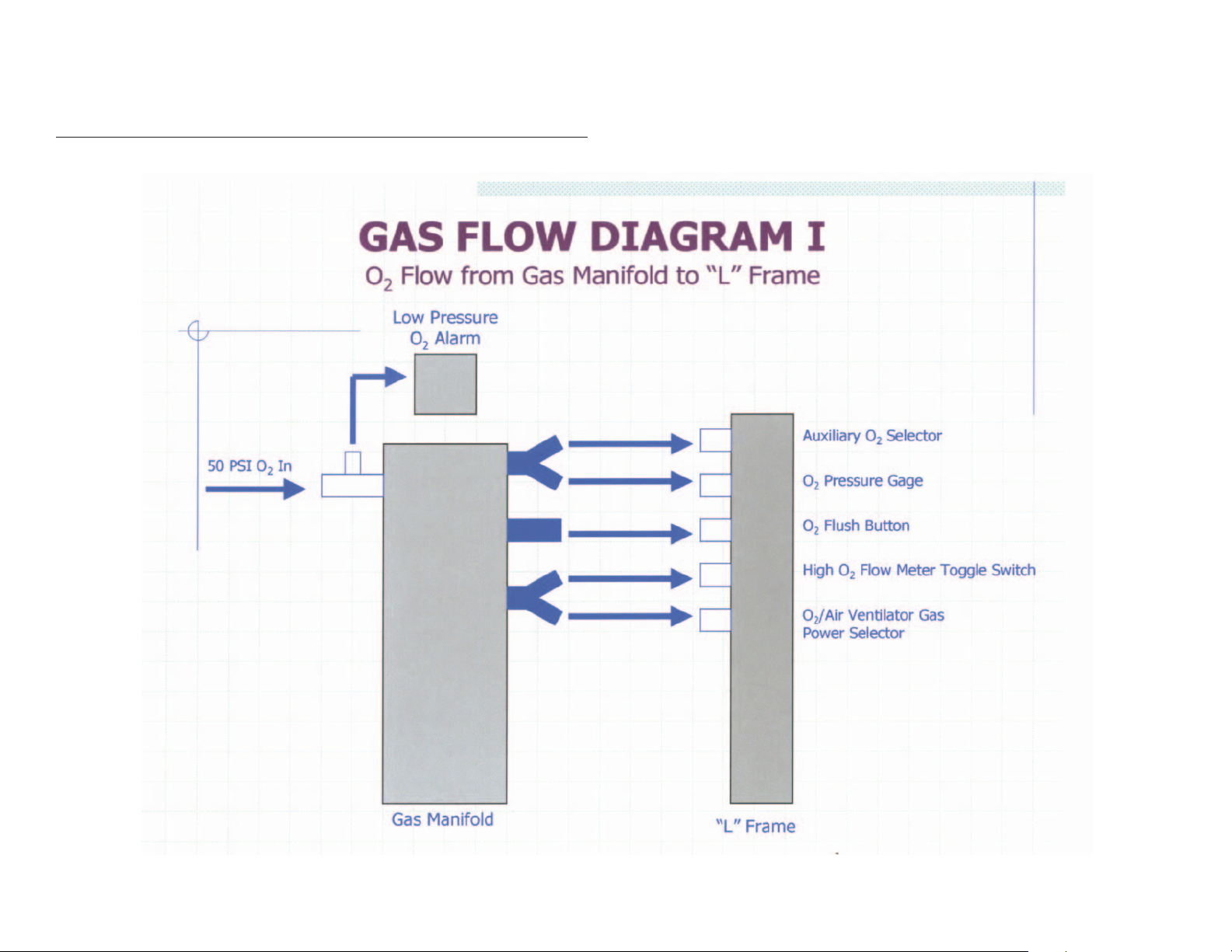
GAS FLOW DIAGRAM I
O2Flow from Gas Manifold to “L” Frame
24
Page 25
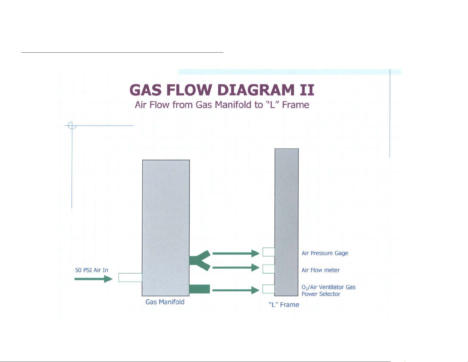
GAS FLOW DIAGRAM II
Air Flow from Gas Mnifold to “L” Frame
25
Page 26
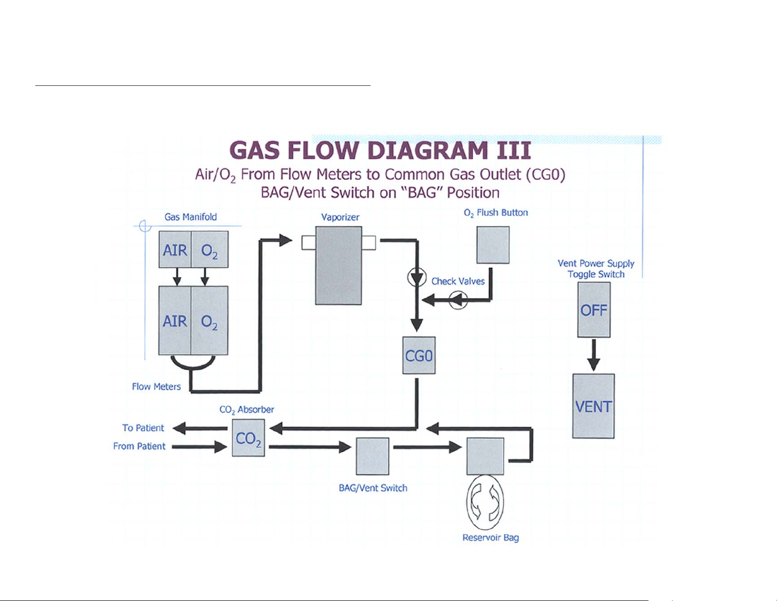
GAS FLOW DIAGRAM III
Air/O2 From Flow Meters to Common Gas Outlet (CGO)
Bag/Vent Switch on “BAG” Position
26
Page 27

GAS FLOW DIAGRAM IV
Air/O2 From Flow Meters to Common Gas Outlet (CGO)
Bag/Vent Switch o “Vent” Position
27
Page 28

GAS FLOW DIAGRAM V
Gas Flow From O2 Concentrator to O2 Flow Meter
28
Page 29

ITEMS FURNISHED WITH DELIVERY OF EACH MACHINE
Effective Date: March, 2004
ADDITIONAL ITEMS NEEDED FOR OPERATION AND MAINTENANCE
29
DESCRIPTION
One each oxygen pressure reducing regulator, DISS
—
One each oxygen pressure reducing regulator, Yoke-type
—
One each Air pressure reducing regulator, DISS
—
One each oxygen high pressure hose, 15”
—
One each oxygen high pressure hose, 24”
—
One each Air high pressure hose, 15”
—
Bag/vent switch mounted on support arm w/mounting knob & screw
—
absorber support arm with Mounting Knob
— CO2
One each King Systems CO2 absorber with adapters and reservoir bag
—
One each King Systems Patient Tubing Circuit
—
One each hose, b/v switch to bellows, color coded blue
—
One each hose, b/v switch to CO2 absorber, color coded green
—
One each hose, ventilator outlet to bellows inlet, with 17mm adapter, color coded red
—
One each low pressure bulb with Comon Gas Outlet adaptor
—
One each Pre-Use Checklist
—
One each Set-Up Instructions Card
—
One each Penlon vaporizer manual
—
One each CD with Operators Manual and Service Manual
—
One each Mapleson “A” Jackson-Reese CGO adaper
—
One each Waste Gas Scavenger
—
One each Anesthesia Machine Carrying Case
—
One each Carrying Case to Machine Securing Bolt
—
One each Cylinder Holder for Carrying Case
—
One each Air Compressor with Carrying Case
—
One each Water Trap for Air Compressor
—
One each Oxygen Monitor, Mounting Clamp and Plastic Sensor Adapter
—
One each PEEP Valve and Accessory Tubing with Connector
—
One each Military Accessory Bundle
—
One each Respirometer with Adapters
—
PART NO.
P/N 26.1
P/N 26.0
P/N 26.2
P/N 26.4
P/N 26.3
P/N 26.5
P/N 14.0 and 14.2
P/N 15.0 and 14.2
P/N A-116
P/N A-117
P.N 20.11
P.N 20.0
P/N 20.2 and 20.3
P/N 16.0
P/N 25.3
P/N 25.2
P/N 25.1
P/N 25.0
P/N A-107
P/N 16.0
P/N A-103
P/N A-114.1
P/N A-103
P/N A-100
P/N A-102
P/N A-105 and A-106
P/N A-110
P/N A-109
P/N A-111
Note: “Military specified” means military provided part or component
“Part #” means can be obtained from Oceanic Medical Products, Inc.
DESCRIPTION
1. Maintenance
Annual Service Kit
—
One each regular screwdriver
—
One each 1/16” Allen’s wrench
—
One each Cresent wrench
—
One each rubber test lung, 1 liter capacity
—
One each mechanical test lung or electrical-mechanical test lung
—
Patient tubing circuit for annesthesia machines, any brand
—
Small tube of Krytox or any brand of oil-free lubricant
—
2. Operations
Spare, reusable King Systems CO2 absorber, refillable
—
Case(s), disposable King Systems CO2 absorber, pre-filled
—
Spare, oxygen sensor for P/N A-105 Oxygen Monitor
—
Additional anesthetic vaporizer, agent specific
—
Aluminum mobile trolley for CSH and general hospital use
—
Soda lime in container, any capacity
—
Oxygen cylinders, “E” or “D” size
—
PART #
A-108
Military specified
Military specified
Military specified
A-118
Military specified
Military specified
A-119
KAB-009
KAB-008
A-105-A
24.0
A-104
Military specified
Military specified
Page 30

ARMY BILL OF MATERIALS
DATE INITIATED: JAN. 4, 2002
ARMY BILL OF MATERIALS – CONT’D.
30
PA RT # DESCRIPTION
1.0 L - Frame
2.0 Flowmeter Pair
2.1 1/8-inch Hose Barb
2.2 Male Connector
2.3 Knob, Green, Fluted
2.4 Flowmeter Guard Bar
3.0 CGO Coupling Body
3.1 CCO Coupling Insert
4.1 O2 Flush Button
4.2 Acutator
2.1 1/8-inch Hose Barb
4.3 Elbow
5.0 Vent On/Off Switch
4.3 Male Elbow
6.0 High/Low O2 Selector Toggle Switch
2.2 Male Connector
4.3 Male Elbow
7.0 Air Press Gauge
7.1 Female Coupling
4.3 Elbow
8.0 O2 Press Gauge
9.0
7.1 Female Coupling
4.3 Elbow
9.0 O2 Auxiliary Flow Selector
4.3 Elbow
10.0 Main Body Frame
10.1 Rods, Steel/Brass
10.2 1/4 – 20 Rod Screws
10.3 Dowel Pin Absorber Mount
10.2 1/4 – 20 Rod Screws
2.1 1/8-inch Hose Barb
7.1 Female Coupling
7.2 Y-Connector
PART NO. DESCRIPTION
11.0 Gas Manifold
11.1 Air DISS Adapter
11.2 Metal Spacer-Air
11.3 Bronze Filter
11.4 O2 DISS Adapter
11.5 Metal Spacer-O2
11.3 Bronze Filter
2.2 Male Connector
7.2 Y Connector
12.0 Ventilator Container
12.1 Container Front Plate
12.2 Container Back Plate
12.2.1 Container Top Plate
12.3 Plastic Valve Spacer
12.4 Alum Spacer Posts
12.5 8/32 x 1 1/4 Brass Screws
12.6 Exhalation Valve
12.7 Plastic Exhalation Valve Tee
12.8 Pressure Relief Valve
12.8.1 Plastic Adapter
12.8.2 Tee Adapter
12.8.3 Hose Nipple Adapter
12.9 Acrylic Block/Fittings
12.5 8/32 x 1 1/4 Brass Screws
12.10 Timing Valves, Inspiratory and Expiratory Time
12.11 Air Volume Tank
12.12 Street Elbow
12.13 Nipple
12.14 1/8" Countersink Plug
12.14 Flow Accelerator Components "A" / "B"
12.16 Inspiratory Flow Valve 1 1/32"
12.16-A Insp Flow Valve Nut
12.17 Insp Flow Valve Bracket
12.18 8-32 Brass Nuts
Page 31

ARMY BILL OF MATERIALS – CONT’D.
ARMY BILL OF MATERIALS – CONT’D.
31
PA RT NO. DESCRIPTION
12.19 Pressure Gauge, Dual Scale, Non-Magnetic
12.20 Pressure Gauge Bracket
12.18 8-32 Brass Nuts
12.21 5/40 x π Brass Screw
12.22 Aluminum Exhalation Valve Bracket
12.23 Bracket 8-32 x π Screws
12.24 Reduced Branch
12.25 Cross Union "x"
12.26 Urethane Tubing, 1/8" ID, 9 ft.
12.27 6-32 x π Brass Screws
12.28 8-32 x π Brass Screws
12.29 6-32 x 1/8 Brass Screws
12.30 Flow Control Locking Knob
12.31 Time Valves Locking Knobs
13.0 Bellows Complete
14.0 Bag/Vent Switch
14.1 B/V Switch Arm
14.1.1 Coupling Body with one way shutoff valve
14.1.2 Hose Barb
14.2 1/8 x ∏ Holding Knob
15.0 CO2 Absorber Arm
14.2 1/8 x ∏ Holding Knob
16.0 Scavenger, Waste Gas
17.0 Bulb, Squeeze/Low Pressssure Testing
3.1 CGO Adapter for Bulb
18.0 Alarm, Hi Pressure Box
18.1 Electric Switch
18.2 Switch Cover
18.3 Alarm Buzzer
18.4 Alarm Plunger
18.5 9 Volt Battery
18.6 1/8 x 10-32 fitting
PA RT NO. DESCRIPTION
18.7 On Off Switch
19.0 Alarm, Lo Pressure Box
19.1 Low Pressure Switch
18.3 Alarm Buzzer
18.5 9 Volt Battery
18.6 1/8 x 10-32 fitting
18.7 On/Off Switch
7.1 Extender
20.0 Tubing, Color Green
20.1 Tubing, Color Blue
20.2 Tubing, Color Red
20.3 Adapter, from Red Tubing to Bellows 17mm Inlet, Red
21.0 Label, "L" Frame
21.1 Label, Vaporizer Warning
21.3 Label, Ventilator, Front Panel
21.4 Label, Ventilator, Side Panel
21.5 Label, Magellan 2200, Large Oval
21.5.1 Label, Magellan 2200, Small Oval for Trolley
21.6 Label, Air Flowmeter Knob
21.7 Label, O2 Flowmeter Knob
21.8 Label, Pressure Relief Valve/Scavenger Port Knob
21.9 Label, O2 Concentrator Inlet
21.10 Label, Fed Law Restricts Use
21.11 Label, Low Pressure, from O2 Concentrator, O2 Alarm
21.12 Label, Hi Pressure O2 Alarm
21.13 Label, Front Manifold
21.14 Label, O2 Out, 2"
21.15 Label, O2 In ≤"
21.16 Label, Air Out ≤"
21.17 Label, To Absorber/Pressure Gauge
21.18 Label, Serial #
21.19 Label, Factory Address
Page 32

ARMY BILL OF MATERIALS – CONT’D.
ARMY BILL OF MATERIALS – CONT’D.
32
PA RT NO. DESCRIPTION
21.20 Label, To Scavenger
21.21 Label, To Bellows
21.22 Label, O2 Pressure
CARRYING CASE INSERT LABELS
21.23 Label, Water Trap
21.26 Label, Regulator
21.27 Label, Scavenger
21.28 Label, Respirometer
21.29 Label, Absorber Canister
21.30 Label, Oxygen Monitor
21.31 Label, Regulator/Yoke
21.32 Label, Flow Arrow for Auxiliary Flow Selector
21.33 Label, Caution Energizing Ventilator
21.34 Label, Oceanic Square
21.35 Label, O2/Air Inlet Locations for Gas Manifold
21.36 Label, Caution, for Air Compressor Use
22.0 Tubing Set, from FM's
22.1 Tubing, from Vaporizer
22.2 Tubing, from CGO
22.3 Valve, One Way
22.4 Tee Connector
23.0 Vaporizer Retainer
23.1 Retainer Holding Knobs
24.0 Vaporizer
24.1 Vaporizer End Male end
24.2 Vaporizer End Female
24.3 Felt Pads
24.4 Key, Agent Specific
24.5 Holding Knobs
25.0 Manual, Oper/Serv CD
PA RT NO. DESCRIPTION
25.1 Penlon Vaporizer Manual
25.2 Card, Set-up Machine
25.3 Card, Pre-Use Checklist
26.0 O2 Regulator, yoke
26.1 O2 Regulator, DISS
26.2 Air Regulator, DISS
26.3 Oxygen Hose, 24"
26.4 Oxygen Hose, 15'
26.5 Air Hose, 15'
Accessories ** indicates included in military delivery of goods
A-100 ** A/C Complete
A-101 Air Compressor
A-102 ** Water Trap, for Air Compressor
A-103 AC Carrying Case
A-104 Aluminum Trolley, for General Hospital Use
A-105 ** Oxygen Monitor
A-105-A ** Oxygen Sensor
A-106 ** Oxygen Tee Adapter for Oxygen Sensor
A-107 ** Mapleson Adaptor to fit into CGO
A-108 Annual Service Kit
Bellows, latex free
Tubing kit w/valves (for Flowmeters to vaporizer/vaporizer to CGO/Flush to CGO/CGO to CO2
canister with metal end caps for vaporizer)
Manifold filters (3) and (3) metal spacers
Tweezers for removing filters and spacers
1/16" Allen's wrench
Squeeze bulb with CGO adapter
Tubing, color coded (3) and red adapter
Instuctions for Service Sheet
Krytox lubricant, tube, ∏ oz
Washer, Press Red Regulator, Yoke, (2 ea)
Page 33

ARMY BILL OF MATERIALS – CONT’D.
PA RT NO. DESCRIPTION
A-109 ** ReSposable Bundle
Surgical masks, size 0-5, inclusive (6 total masks
Reusable mask hook rings (2)
Breathing tube 16mm x 72"
Breathing bag 1.0 L silicone (1)
Breathing bag 3.0 L silicone (1)
Elbow, polysulfone, white cap
Wye, fixed, autoclavable
Tee, fixed, autoclabavle
Adapter, autoclavable, 22 ID x 15 ID/22 OD
Silicone breathing tube, 16mm x 12"
Headstrap
Resusable CO2 Absorber
Connector - KAB 1930 D
Reusable Scavinging Tubing - 3 pieces, each 12" long
3.0 L breathing bag
A-110 ** PEEP Valve
A-111 ** Respirometer, Mechanical, Hand-Held
A-112 Rubber bellows only
A-113 ** Scavenger Tubing Kit
A-114 ** Machine Carrying Case
A-114.1 ** Mounting Bolt, Carry CS
A-115 ** Cylinder Holder, Crry CS
A-116 ** King Systems CO2 Refillable Absorber w/out APL
A-117 ** King Systems Patient Tubing Circuit
A-118 Rubber Test Lung
A-119 Krytox lube, ∏ oz Tube
33
Page 34

MAGELLAN-2200 ANESTHESIA MACHINE – FRONT
34
Page 35

MAGELLAN-2200 ANESTHESIA MACHINE – BACK
35
 Loading...