

Page 1

DRAGON™ D131/M131
Reference Manual
Page 2

Page 3

Dragon™ D131/M131
REFERENCE MANUAL
Page 4

DATALOGIC S.p.A.
Via Candini 2
40012 - Lippo di Calderara di Reno
Bologna - Italy
Dragon™ D131/M131 Reference Manual
Ed.: 01/2007
This manual refers to software version 1.00 and later
ALL RIGHTS RESERVED
Datalogic reserves the right to make modifications and improvements without prior notification.
Datalogic shall not be liable for technical or editorial errors or omissions contained herein, nor for incidental or
consequential damages resulting from the use of this material.
Product names mentioned herein are for identification purposes only and may be trademarks and or
registered trademarks of their respective companies.
© Datalogic S.p.A. 2007
Rev. A
Page 5

CONTENTS
GENERAL VIEW ......................................................................................... ix
1 INTRODUCTION .......................................................................................... 1
2 INSTALLATION............................................................................................ 2
2.1 Dragon™ D131 Interface Cable Connections ............................................... 2
2.2 OM-30X0 Interface Cable Connections ........................................................ 4
2.3 RS232 Connection........................................................................................5
2.4 USB .............................................................................................................. 5
2.5 IBM USB POS............................................................................................... 5
2.6 WEDGE Connection .....................................................................................5
2.7 PEN Emulation Connection........................................................................... 5
2.8 Network Connections....................................................................................6
2.8.1 Network Cabling............................................................................................ 6
2.8.2 Network Termination.....................................................................................8
2.9 Dragon™ M131 Battery Maintenance...........................................................9
2.9.1 Battery Charging ........................................................................................... 9
2.9.2 Replacing Dragon™ M131 Batteries............................................................. 9
3 DRAGON™ M131 SYSTEM AND NETWORK LAYOUTS ..........................10
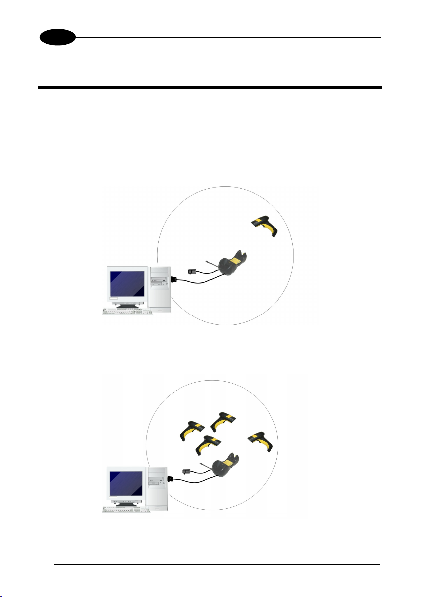
3.1 Stand Alone Layouts...................................................................................10
3.1.1 Point-to-Point Reader Layout...................................................................... 10
3.1.2 Stand Alone Layout with Multiple Readers.................................................. 10
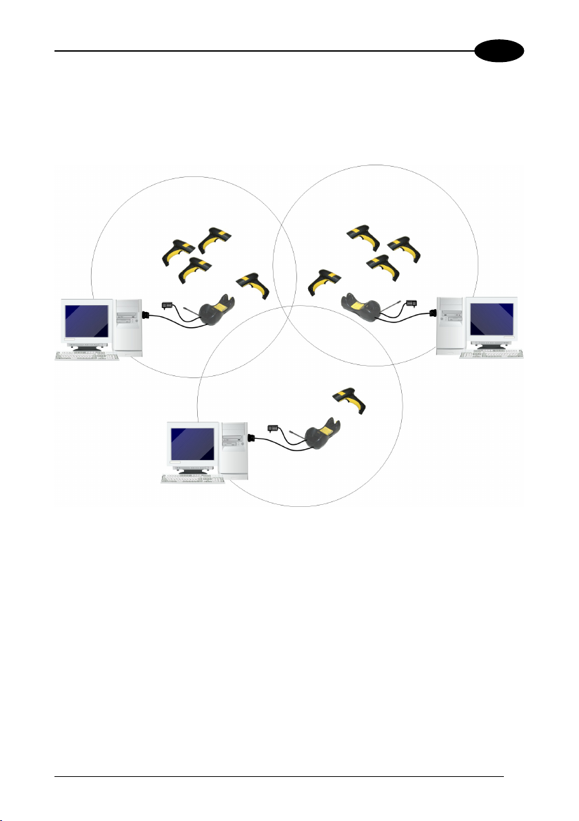
3.1.3 Multiple Stand Alone Layouts...................................................................... 11
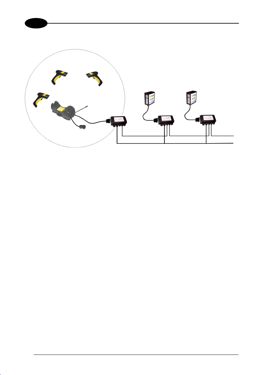
3.1.4 C-BOX Layout............................................................................................. 12
3.2 Multidrop STAR-System™ Network Layouts ..............................................13
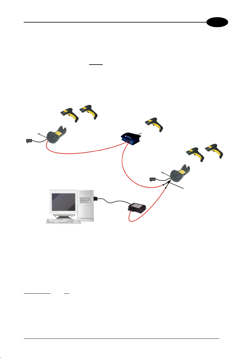
3.2.1 Host Master Layout..................................................................................... 13
3.2.2 OM-3000 Master Layout ............................................................................. 14
3.2.3 Master OM-3000 Network Troubleshooting ................................................ 15
4 CONFIGURATION...................................................................................... 16
4.1 Configuration Methods................................................................................ 16
4.1.1 Reading Configuration Barcodes ................................................................ 16
4.1.2 Using Datalogic Aladdin™ .......................................................................... 16
4.1.3 Copy Command.......................................................................................... 16
4.1.4 Sending Configuration Strings from Host.................................................... 17
4.2 Setup Procedures .......................................................................................17
4.3 Dragon™ D131 Setup................................................................................. 18
4.4 Dragon™ M131/OM-30X0 Point-to-Point Setup ......................................... 18
4.5 Dragon™ M131/OM-30X0 Stand Alone Setup............................................ 19
4.5.1 Using Multiple M-Series Readers With Same Cradle.................................. 21
4.5.2 Dragon™ M131/STAR-Modem™ in Stand Alone Mode ............................. 22
4.6 Dragon™ M/STAR-System™ Setup ........................................................... 23
iii
Page 6

4.7 OM-3000 STAR-System™ Network Setup ................................................. 25
4.8 Interface Selection ...................................................................................... 27
4.9 USB Reader Configuration.......................................................................... 31
4.10 Changing Default Settings .......................................................................... 33
RS232 PARAMETERS............................................................................... 34
Baud Rate................................................................................................... 35
Parity........................................................................................................... 35
Data Bits .....................................................................................................36
Stop Bits...................................................................................................... 36
Handshaking ............................................................................................... 36
Ack/Nack Protocol....................................................................................... 37
FIFO............................................................................................................ 37
Inter-character Delay .................................................................................. 37
Rx Timeout.................................................................................................. 38
Serial Trigger Lock...................................................................................... 38
USB PARAMETERS ..................................................................................39
Handshaking ............................................................................................... 40
Ack/Nack Protocol....................................................................................... 40
FIFO............................................................................................................ 40
Inter-character Delay .................................................................................. 41
Rx Timeout.................................................................................................. 41
Serial Trigger Lock...................................................................................... 41
Keyboard Nationality................................................................................... 42
FIFO............................................................................................................ 43
Inter-character Delay .................................................................................. 44
Inter-code Delay.......................................................................................... 44
USB Keyboard Speed................................................................................. 44
iv
WEDGE PARAMETERS ............................................................................45
Keyboard Nationality................................................................................... 46
Caps Lock................................................................................................... 47
Caps Lock Auto-Recognition (IBM AT compatible only) .............................. 48
Num Lock.................................................................................................... 48
Inter-character Delay .................................................................................. 48
Inter-code Delay.......................................................................................... 49
Keyboard Setting ........................................................................................ 49
Control Character Emulation....................................................................... 51
PEN EMULATION ......................................................................................52
Operating Mode .......................................................................................... 53
Minimum Output Pulse................................................................................ 54
Conversion to Code 39 (D131 Series Only)................................................ 55
Conversion to Code 39 and Code 128 (M131 Series Only) ........................ 55
Overflow...................................................................................................... 55
Page 7

Output Level................................................................................................ 56
Idle Level..................................................................................................... 56
Inter-Block Delay......................................................................................... 56
NETWORK PARAMETERS ....................................................................... 57
RS485 Network........................................................................................... 58
Network Baud Rate..................................................................................... 58
Slave Address Range ................................................................................. 59
Network Warning Message ......................................................................... 59
Reception Warning Message ...................................................................... 59
Master Cradle Header................................................................................. 60
Master Cradle Terminator ........................................................................... 61
DATA FORMAT.......................................................................................... 62
Code Identifier............................................................................................. 64
Custom Code Identifier ............................................................................... 64
Header ........................................................................................................ 65
Terminator................................................................................................... 66
Special Keys ............................................................................................... 67
Field Adjustment .........................................................................................68
Field Adjustment Character......................................................................... 69
Code Length Tx .......................................................................................... 69
Character Replacement .............................................................................. 70
Address Stamping (M131 Series Only)....................................................... 72
Address Delimiter (M131 Series Only)........................................................ 72
Time Stamping (M131 Series Only) ............................................................ 73
Time Stamping Delimiter (M131 Series Only)............................................. 73
POWER SAVE............................................................................................ 74
Sleep State ................................................................................................. 75
Enter Sleep Timeout ................................................................................... 75
READING PARAMETERS .........................................................................76
Trigger Type................................................................................................ 77
Trigger Signal.............................................................................................. 77
Trigger Click................................................................................................ 77
Trigger-off Timeout ..................................................................................... 78
Flash Mode ................................................................................................. 78
Reads per Cycle ......................................................................................... 78
Safety Time................................................................................................. 79
Beeper Intensity .......................................................................................... 79
Beeper Tone ............................................................................................... 80
Beeper Type ............................................................................................... 80
Beeper Length ............................................................................................ 80
Good Read Spot Duration........................................................................... 81
Aiming System ............................................................................................ 81
v
Page 8

Cradle Beeper Intensity .............................................................................. 81
DECODING PARAMETERS....................................................................... 82
Ink Spread................................................................................................... 83
Overflow Control ......................................................................................... 83
Interdigit Control.......................................................................................... 83
Decoding Safety.......................................................................................... 84
Puzzle Solver™ .......................................................................................... 84
CODE SELECTION .................................................................................... 85
Auto-configuration....................................................................................... 86
EAN/UPC Family ........................................................................................ 88
2/5 Family ................................................................................................... 94
Code 39 Family........................................................................................... 95
Code 128 Family......................................................................................... 96
Code 93 ...................................................................................................... 97
Codabar Family........................................................................................... 97
MSI ............................................................................................................. 99
Code 11 .................................................................................................... 100
Code 16K.................................................................................................. 101
Code 49 .................................................................................................... 101
RSS Codes ............................................................................................... 102
ADVANCED FORMATTING..................................................................... 103
Concatenation........................................................................................... 104
Advanced Formatting................................................................................ 107
RADIO PARAMETERS ............................................................................ 122
Radio Protocol Timeout ............................................................................ 123
Power-Off Timeout.................................................................................... 123
Transmission Mode................................................................................... 124
Beeper Control for Radio Response ......................................................... 124
Single Store .............................................................................................. 125
Batch Mode............................................................................................... 126
Find Me..................................................................................................... 126
DISPLAY PARAMETERS ........................................................................ 127
Date and Time .......................................................................................... 128
Contrast .................................................................................................... 128
Font Size................................................................................................... 128
Backlight ................................................................................................... 128
Display-Off Timeout ..................................................................................129
Display Mode............................................................................................ 129
Keypad...................................................................................................... 130
5 REFERENCES ......................................................................................... 131
5.1 RS232 Parameters ................................................................................... 131
vi
Page 9

5.1.1 Handshaking ............................................................................................. 131
5.1.2 ACK/NACK Protocol ................................................................................. 132
5.1.3 FIFO.......................................................................................................... 133
5.1.4 RX Timeout ............................................................................................... 134
5.2 Pen Parameters........................................................................................ 134
5.2.1 Minimum Output Pulse.............................................................................. 134
5.2.2 Conversion to Code 39 and Code 128...................................................... 134
5.2.3 Overflow.................................................................................................... 135
5.2.4 Output and Idle Levels .............................................................................. 135
5.2.5 Inter-Block Delay....................................................................................... 136
5.3 Network Parameters ................................................................................. 136
5.3.1 Slave Address Range First/Last................................................................ 136
5.3.2 Network Warning Message ....................................................................... 136
5.3.3 Reception Warning Message .................................................................... 137
5.3.4 Master Header/Terminator Selection ........................................................ 137
5.4 Data Format.............................................................................................. 137
5.4.1 Header/Terminator Selection .................................................................... 137
5.4.2 Define Special Key Sequence................................................................... 139
5.4.3 Address Stamping..................................................................................... 146
5.4.4 Address Delimiter...................................................................................... 146
5.4.5 Time Stamping Format ............................................................................. 147
5.4.6 Time Stamping Delimiter........................................................................... 147
5.5 Power Save............................................................................................... 147
5.5.1 Sleep State ............................................................................................... 147
5.5.2 Enter Sleep Timeout ................................................................................. 148
5.6 Reading Parameters ................................................................................. 148
5.6.1 Trigger Signal............................................................................................ 148
5.6.2 Trigger Click.............................................................................................. 148
5.6.3 Trigger-Off Timeout................................................................................... 148
5.6.4 Reads per Cycle ....................................................................................... 148
5.6.5 Safety Time............................................................................................... 149
5.7 Decoding Parameters ...............................................................................149
5.7.1 Ink-Spread ................................................................................................ 149
5.7.2 Overflow Control ....................................................................................... 149
5.7.3 Interdigit Control........................................................................................ 150
5.8 Radio Parameters (M131 Series Only) ..................................................... 150
5.8.1 Radio Protocol Timeout ............................................................................ 150
5.8.2 Power-Off Timeout.................................................................................... 150
5.8.3 Transmission Mode................................................................................... 150
5.8.4 Beeper Control for Radio Response ......................................................... 151
5.8.5 Single Store .............................................................................................. 151
5.8.6 Batch Mode............................................................................................... 152
5.8.7 Find Me (Dragon M131 only) .................................................................... 153
5.9 Display Parameters (Some M131 Models Only) .......................................153
5.9.1 Display Mode............................................................................................ 153
5.10 Configuration Editing Commands ............................................................. 154
vii
Page 10

5.11 Custom Default Configuration ................................................................... 155
5.12 Code Type Recognition ............................................................................ 155
5.13 Configuration Copying Commands ........................................................... 156
5.13.1 Copy Dragon™ D131 Series ..................................................................... 156
5.13.2 Copy Dragon™ M131 Series ..................................................................... 157
5.13.3 Copy OM-30X0 ......................................................................................... 158
5.14 Default Parameters for POS Terminals..................................................... 159
5.15 Firmware Upgrade .................................................................................... 160
6 MESSAGE FORMATTING ....................................................................... 161
6.1 Messages from Host to Gun ..................................................................... 161
6.1.1 Cursor Control........................................................................................... 162
6.1.2 Font Selection........................................................................................... 163
6.1.3 Clearing Display........................................................................................ 163
6.1.4 LED and Beeper Control........................................................................... 163
6.1.5 Setting RTC .............................................................................................. 164
6.2 Messages From Gun Command Keys ...................................................... 164
7 TECHNICAL FEATURES......................................................................... 166
7.1 Dragon™ D131 ......................................................................................... 166
7.2 Dragon™ M131......................................................................................... 167
7.3 OM-30X0 / C-3000.................................................................................... 168
7.4 System and Radio Features...................................................................... 169
7.5 Status Indicators ....................................................................................... 169
7.6 Reading Diagrams .................................................................................... 172
A HOST CONFIGURATION STRINGS........................................................ 173
B CODE IDENTIFIER TABLE...................................................................... 187
C HEX AND NUMERIC TABLE ...................................................................190
viii
Page 11
t
y
r
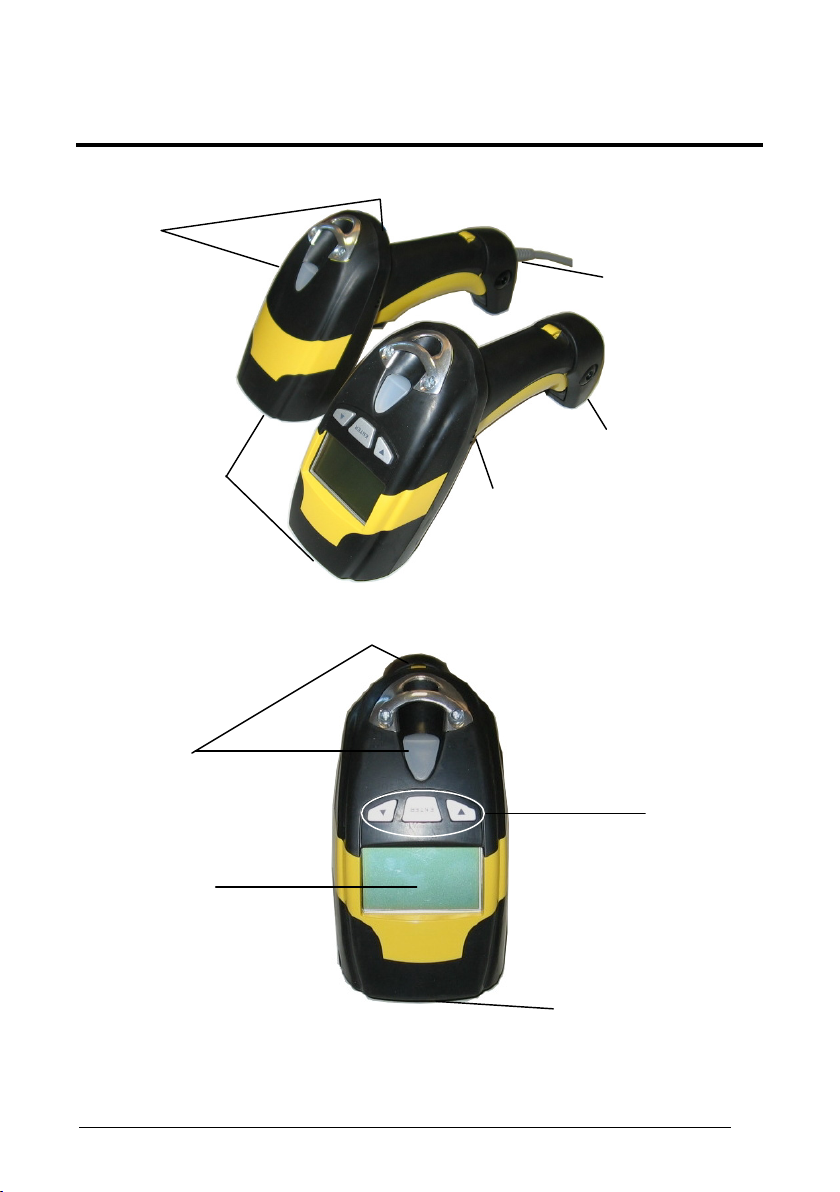
GENERAL VIEW
LEDs
Laser Outpu
Window
Figure A – DRAGON™ D131 and M131 Series Readers
DRAGON™ D131/M131 READERS
Trigger
DRAGON™ D131
Cable Connecto
DRAGON™ M131
Batter
Cover
LEDs
Keypad
Display
Figure B – DRAGON™ M131 Series Readers with Display
Laser Output Window
ix
Page 12

LEDs
OM-30X0 / C-3000 CRADLES
Figure C – OM-3000
LEDs
x
Figure D – C-3000
Page 13

INTRODUCTION
1
1 INTRODUCTION
Datalogic renews its range of industrial laser scanners introducing the Dragon™
family: Dragon™ Desk and Dragon™ Mobile. Robustness and ergonomics remain
unsurpassed: clearly audible beeper and bright "good read" LEDs for areas where
noise levels are normally high; the aim mode, which helps point to the right code, has
now been extended to the whole Dragon™ family. Optical parts are completely
suspended on shock absorbers and a careful choice of the body materials, such as
the co-moulded rubber, protect the Dragon™ from damage due to "falls".
New enhanced architecture, based on an M16 high-speed microprocessor, enables
exceptional performance for promptness and reading speed of standard codes as
well as the ability to read poorly printed and damaged codes. Puzzle Solver
Technology™, a patent from Datalogic, adds further strength to the Dragon™
powerful engine.
In all applications where mobility is a value, the new Dragon™ M represents the key
to increase productivity and flexibility in the working area. Dragon™ M
communicates through a low power, license-free radio in the 433 MHz band (910
MHz for USA version) and allows bi-directional communication between the base
station and the host. Dragon™ M also includes a display and a 3 push-button
keypad. Thanks to these features, the operator can receive information from the host,
interact with the central system and visualize the code read. The cordless system
offers scalable solutions to solve simple applications and complex projects:
• Point to point: each gun is associated with its own base station;
• Multipoint: up to 32 guns transmit data to one base station;
• Network: to cover a wide area, connecting up to 16 bases and 512 guns
Dragon™ M is 100% compatible with STAR-System™, the Datalogic RF narrow
band solution for mobile applications that provides the widest family of narrow band
devices on the market.
Your Dragon™ reader is supplied with its own Quick Reference Manual which
provides connection diagrams, basic application parameter settings, default values,
and specific technical features. You can use either your reader's Quick Reference
Manual or this Manual for initial configuration in order to set the default values and
select the interface for your application. This manual provides all the necessary
information for complete mechanical installation and system software configuration.
simultaneously working in automatic roaming.
1
Page 14
2
DRAGON™ D131/M131
2 INSTALLATION
Connections should always be made with power OFF!
CAUTION
2.1 DRAGON™ D131 INTERFACE CABLE CONNECTIONS
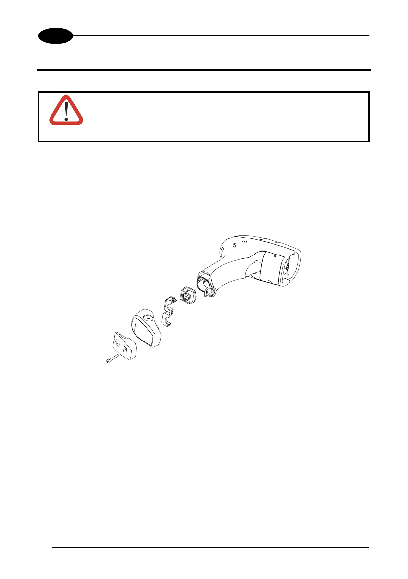
The Dragon™ D131 reader incorporates a multi-standard interface which can be
onnected to a Host by plugging the correct interface cable into the connector and
c
osing the cable cover.
cl
A
B
C
E
A. Rubber boot
B. Rubber boot cl
C. Cover
. Strain relief
D
. Screw
E
2
D
ip
Page 15
INSTALLATION
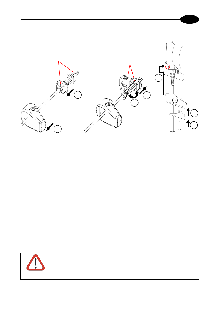
Follow the given procedure for correct cable insertion:
2
Align
Align
5
2
3
4
6
1
7
Slip the cover over the cable.
Push the rubber boot completely over the connector. Take care that the rubber
boot ma
rk is aligned to the connector clip.
Pull the rubber boot towards the connector until it covers and is flush with the
connector moulding.
Lock the rubber boot clip around the r
ubber boot aligning them as shown in the
figure.
Insert the assembly (connector + rubber boot locked through clip) into the reader
connector. Push
the cover along the cable towards the reader handle and make it
hook over the yellow tooth therefore closing the handle.
Insert the strain re
lief into the cover.
screw into the strain relief and tighten to fix the whole assembly to the
Insert the
reader ha
ndle.
CAUTION
Connections should always be made with power OFF!
3
Page 16
2
DRAGON™ D131/M131
2.2 OM-30X0 INTERFACE CABLE CONNECTIONS
Po
wer
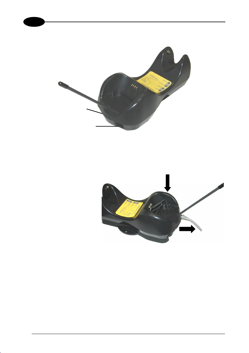
Interface Cable
OM-30X0 Connectors
The OM-30X0 incorporates a mu
ost by simply pluggin
H
e base of the cradle. In addition the cradle must be connected to an external power
th
ly.
supp
g the correct interface cable into the Host connector, placed on
lti-standard interface which can be connected to a
To disconnect the cable, insert
a paper clip or other similar
object into the hole
corresponding to the Host
connector on the body of the
cradle.
Push down on the clip while
unplugging the cable.
Disconnecting the OM-30X0 Cable
4
Page 17
INSTALLATION
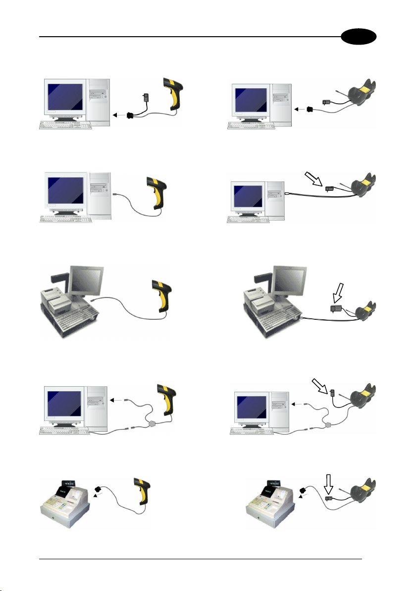
2.3 RS232 CONNECTION
2
2.4 USB
2.5 IBM USB POS
2.6 WEDGE CONNECTION
(if required)
(if required)
(if required)
2.7 PEN EMULATION CONNECTION
(if required)
5
Page 18
2
DRAGON™ D131/M131
2.8 NETWORK CONNECTIONS
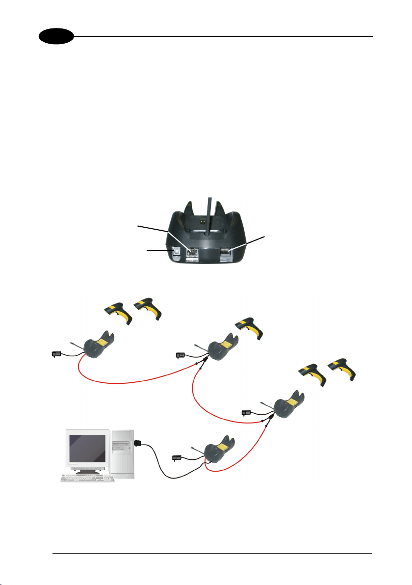
The OM-3000 provides an RS485 multidrop connection to link up to 16 base stations
together in a network layout.
.8.1 Network Cabling
2
The RJ45 connector on the re
S485 multidrop network from one cradle to another. For cradles connected to two
R
fferent devices (network in and network out) an RS485 splitter cable (CAB-428, part
di
number 90A051950) is used. Custo
etween cradles. b
ar panel of the OM-3000 cradle allows propagating the
m cables are used to connect the network
RS485 Network
Power
OM-3000 Connectors
Internal
Termination
RS485 Only
CAB-428 Splitter
RS485 Only
Host
Internal
Termination
USB, or RS232, or Wedge, or Pen Emulation
Example RS485 Network Connection
Multistandard Interface
RS485 Only
6
Page 19
INSTALLATION
V
V
V
2
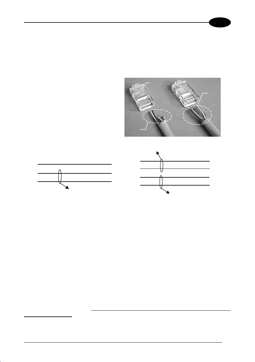
The custom cables have the following specifications:
• twisted pair AWG 24 wires
• 120 Ω impedance
• maximum network cable length 1200 meters
Pin Function Multidrop Cables
1 RS485 +
Pin 1
2 RS485 3 N.C.
4 VDC –
Data
and
Power
Supply
5 VDC –
6 N.C.
7 VDC +
8 VDC +
Data
only
RJ45
5
2
1 1
DC-
RS485RS485+
Twisted Pair - RS485 bus
RJ45
5
2
RJ45
8
5
2
1 1
DC+
DC-
RS485
RS485
Twisted Pair - RS485 bus
RJ45
8
5
2
Twisted Pair - Power supply
When wiring the multidrop cables, note the following:
As with all bus systems, the best overall performance is obtained by keeping cable
length to a minimum.
Pin 8 (or 7) should be connected only if power has to be propagated from a cradle to a
STARGATE™ base station or STAR-Box™ converter via the cable. See par 3.2 for
example network layouts.
Pins 5 (or 4) should always be connected as reference ground.
To avoid excessive voltage drop, it is recommended not to propagate power between
OM-3000 cradles when used as battery chargers but to supply each cradle
individually. The total number of devices which can be connected to a single power
supply depends on the power supply voltage, the wire length and resistance and
therefore the voltage drop.
Do NOT connect VDC+ between network devices that are
individually powered.
7
Page 20
2
DRAGON™ D131/M131
2.8.2 Network Termination
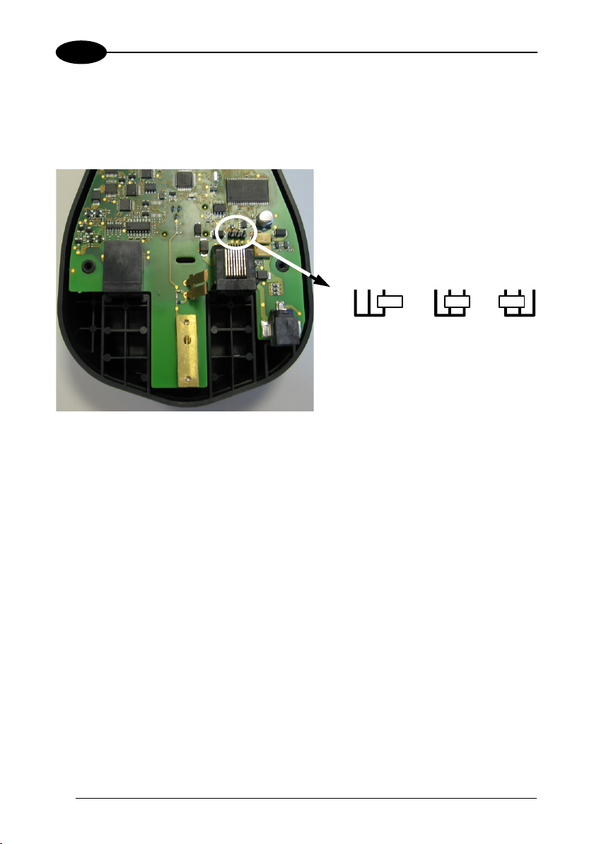
The first and last cradles of the chain (the two ends of the bus) must be properly
terminated. The cradle has an internal terminator that can be selected via jumper.
For this selection you must open the device.
No Termination Static Dynamic
Terminator for Multidrop Network
Static termination works for all network configurations. However, the network is
always under load even when no data transmission takes place.
Dynamic termination can be used for baud rates at or above 38400 and provides less
load on the network when idle.
8
Page 21

INSTALLATION
2
2.9 DRAGON™ M131 BATTERY MAINTENANCE
2.9.1 Battery Charging
Once the system is connected and powered, you can place the Dragon™ M131 into
the cradle to charge the battery.
When the reader is correctly inserted in the cradle, the "Reader" red LED on the cradle
goes on to indicate that the battery is charging. The "Reader" green LED on the cradle
goes on when the battery is completely charged.
2.9.2 Replacing Dragon™ M131 Batteries
To change the batteries in your Dragon™ M131 scanner, unscrew the retaining
screw and extract the battery pack from the reader handle. Then, insert the new
battery pack into the reader handle and tighten the screw.
1
NOTE
WARNING
When the batteries are extracted from the scanner
maintains the current hour and date for about 1 minute.
Do not incinerate, disassemble, short terminals or expose to
high temperature. Risk of fire, explosion. Use specified
charger only. Risk of e
an incorrect type. Dispose of the batteries as required by the
xplosion if the battery is replaced by
relevant laws in force.
2
, a timer
9
Page 22
3
g
DRAGON™ D131/M131
3 DRAGON™ M131 SYSTEM AND NETWORK
LAYOUTS
There are two basic system layouts that can be employed: Stand Alone systems
(including Point-to-Point layouts) and Multidrop STAR-System™ Networks.
3.1 STAND ALONE LAYOUTS
3.1.1 Point-to-Point Reader Layout
Dragon™ M
BIND
Host
OM-30X0
3.1.2 Stand Alone Layout with Multiple Readers
on™ M
Dra
JOIN
Host
In stand alone systems, each cradle is connected to a single Host.
10
BIND
OM-30X0
Page 23
DRAGON™ M131 SYSTEM AND NETWORK LAYOUTS
3
3.1.3 Multiple Stand Alone Layouts
Many stand alone connections can operate in the same physical area without
interference, provided all readers and cradles in the system have different addresses.
Host
Dragon™ M
OM-30X0
JOIN
BIND
gon™ M
Dra
BIND
JOIN
Host
OM-30X0
Dragon™ M
Host
BIND
OM-30X0
Multiple Stand Alone Systems in the Same Area
Since the cradles can communicate to multiple Dragon™ M131 readers, you might
find it useful to employ one or more C-3000 battery chargers in addition to the
OM-30X0 cradle, so that the battery re-charging operation can be performed for
several scanners at the same time.
11
Page 24
3
r
3.1.4 C-BOX Layout
Dragon™ M
JOIN
DRAGON™ D131/M131
Scanne
BIND
C-Box
OM-30X0
System cables to Host
In this layout the OM-30X0 cradle is connected by a dedicated cable using the RS232
interface to a C-BOX connection box as part of a fixed scanner network. This allows the
flexibility of a hand-held reading station integrated into a variety of fixed scanning
applications so that all readers (both fixed and hand-held), in the system provide
communications to the Host.
The various C-BOX models provide many interface types for the Host system such as
RS232, RS485, Profibus.
12
Page 25
DRAGON™ M131 SYSTEM AND NETWORK LAYOUTS
A
3
3.2 MULTIDROP STAR-SYSTEM™ NETWORK LAYOUTS
Even though many stand alone systems can operate in the same physical area without
interfering with each other, it may be desirable to bridge data from multiple base
stations in a network to a
single Host. Dragon™ M131 readers are compatible with
STAR-System™ networks. These networks provide seamless active roaming for any
RF reading device in the system.
3.2.1 Host Master Layout
C
Internal
D
Termination
RS485 + VDC
RS48
5 Only
C
Internal
Termination
C
AB-428 Splitter
B
RS232
RS485 + VDC
A. Host Master with STAR-Link™
B. STAR-Box™ converter
C. OM-3000 slave cradles
D. STARGATE™ base stations
Example Multidrop STAR-System™ Network with Host as Master
In this layout the Host acts as the Master using STAR-Link™ software. The Host is
connected in RS232 to a STAR-Box™ converter which is connected to the first slave in
the RS485 network. In this way the base stations provide communications between a
single Host and all readers in the system. STARGATE™ base stations are used as
slaves in this network. The Slaves at the ends of the network must be terminated (see
the STARGATE™ and STAR-Box™ Installation Manuals and par. 2.8.2).
See par. 4.6 and 4.7 or the Datalogic Aladdin™ Help On-Line for system
configuration specifications.
13
Page 26
3
A
3.2.2 OM-3000 Master Layout
DRAGON™ D131/M131
Internal
Termination
C
RS485 + VDC
Internal
D
RS485 Only
C
CAB-428 Splitter
Termination
RS485 Only
USB, orRS232, or Wedge, or Pen Emulation
B
A. Host
B. OM-3000 Master cradle
C. OM-3000 Slave cradles
D. STARGATE™ base station
Example Multidrop STAR-System™ Network with OM-3000 as Master
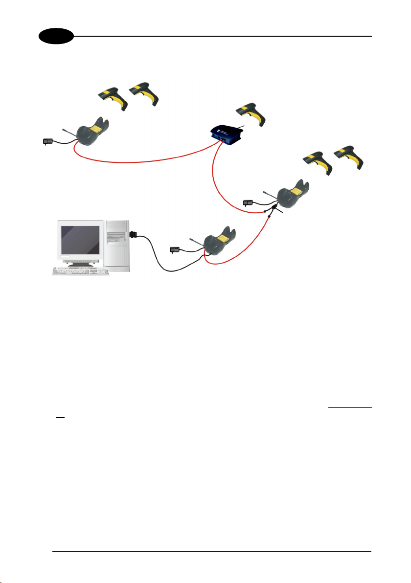
In this layout an OM-3000 cradle acts as the Master. The Host is connected to the
OM-3000 Master using any one of the multi-standard interfaces (RS232, USB,
WEDGE, or PEN Emulation). The Master is then connected to the slaves in the RS485
network. In this way the slave cradles provide communications between a
and
all readers in the system. STARGATE™ base stations can also be used as slaves
single Host
in this network. The devices at the ends of the network must be terminated (see par.
2.8.2).
See pars. 4.6 and 4.7 or the Datalogic Aladdin™ Help On-Line for system
configuration specifications.
14
Page 27

DRAGON™ M131 SYSTEM AND NETWORK LAYOUTS
3
3.2.3 Master OM-3000 Network Troubleshooting
Two diagnostic strings can be sent via RS232 from the Host to the Master cradle in
order to have feedback about the network itself.
#+LSlave
Returns a list of all the Slaves recognized at boot up.
Example:
In a network where the Master cradle has address 0188 and one Slave cradle with
address 0001, the response is:
188
1
#+Alive<xxxx>
Executes a continuous Alive request to the slave xxxx in order to monitor the
performance of the connection. A diagnostic message is displayed on the Host.
Example:
If this command is sent for slave cradle with address 0032, the response is:
/*32: OM-30X0 SOFTWARE RELEASE 1.00 20/10/2006*/
if there are no communication errors
/*32: FAIL*/
if there are communication errors.
To exit from this command, reset the system by cycling power to the Master cradle.
15
Page 28

4
DRAGON™ D131/M131
4 CONFIGURATION
4.1 CONFIGURATION METHODS
4.1.1 Reading Configuration Barcodes
This manual can be used for complete setup and configuration of your reader by
following the setup procedures in this chapter (see par. 4.2 for an overview).
If you wish to change the default settings, this manual provides complete
configuration of your reader in an easy way.
To configure your reader:
1) Open the folded page in Appendix C with the hex-numeric table and keep it
open during the device configuration.
2) Read the Enter Configuration code ONCE, available at the top of each page
of configuration.
3) Modify the desired parameters in one or more sections following the
procedures given for each group.
4) Read the Exit and Save Configuration code ONCE, available at the top of
each page of configuration.
Reference notes describing the operation of the more complex parameters are given
in chapter 5.
4.1.2 Using Datalogic Aladdin™
Datalogic Aladdin™ is a multi-platform utility program providing a quick and userfriendly configuration method via the RS232/USB-COM interface.
It also allows upgrading the software of the connected device (see the Datalogic
Aladdin™ Help On-Line for more details).
4.1.3 Copy Command
A previously configured device (Master), can be used to send its configuration directly
to other devices of the same type (Slaves). The particular procedure for each device is
given in par. 5.13.
16
Page 29
CONFIGURATION
4
4.1.4 Sending Configuration Strings from Host
An alternative configuration method is provided in Appendix A using the RS232
interface. This method is particularly useful when many devices need to be
configured with the same settings. Batch files containing the desired parameter
settings can be prepared to configure devices quickly and easily.
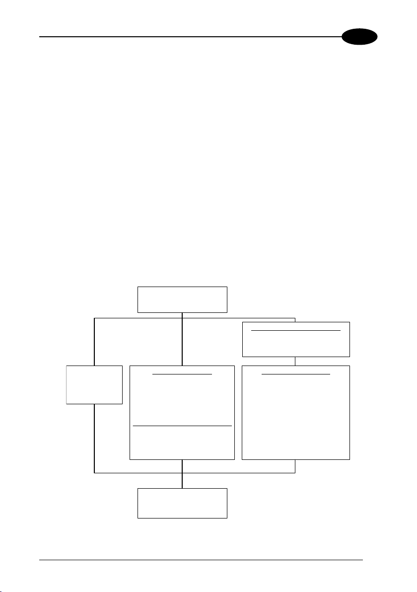
4.2 SETUP PROCEDURES
For Dragon™ D131 Series readers, follow the setup procedures in pars. 4.3, and 4.8.
For Dragon™ M131 Series readers, the setup procedures depend on two basic
applications, Stand Alone or STAR-System™.
Stand Alone applications allow communication with the Host by either the OM-30X0
cradle (par. 4.5), or by the STAR-Modem™ radio modem (par. 4.5.2).
STAR-System™ applications allow communication with the Host through an RS485
network by the STARGATE™ RF base station or by the OM-3000 cradle (par. 4.6
and par. 4.7).
Proceed as shown in the following diagram:
by choosing the setup
Begin Setup
procedure for your Dragon™ reader
as indicated below.
STAR-System™ Network Applications
OM-3000
Par. 4.6
Dragon™ Dx31
Par. 4.3
Par. 4.7
Stand Alone Applications
Dragon™ Mx31/OM-30X0
Par. 4.4
Par. 4.7
Optional Par. 4.4.1
multiple guns per OM-3000
Dragon™ M/STAR-Modem™
Your reader is now ready to read
barcodes using the default setti ngs.
in Stand Alone Mode
Par. 4.4.2
End of Setup
STAR-System™ Applications
Dragon™ Mx31/STAR-System™
STARGATE™
•
• OM-3000 Network
• STAR-Modem™ in STAR-System™ Mode
Par. 4.5
17
Page 30

4
4.3 DRAGON™ D131 SETUP
Read the restore default parameters code below.
1.
Restore Dragon™ D131 Default
DRAGON™ D131/M131
Ì$+$*oÎ
After reading the above code, go to par. 4.8 Interface Selection.
4.4 DRAGON™ M131/OM-30X0 POINT-TO-POINT SETUP
A rapid configuration procedure has been devised for point-to-point applications
where a
and where it is not necessary to set the Date and Time parameters.
A special pre-printed bind-address label provided in the OM-30x0 base station
package can be used to bind the Dragon™ M131 reader to the base station with the
address coded on the label. The address is also written numerically on the label to be
easily recognized. Valid addresses are in the range from 0000 to 1999. Make sure
that all cradles used in the same area have different addresses.
To rapidly configure your point-to-point application:
1.
2.
3.
single reader is associated exclusively with its own OM-30x0 base station
Apply the bind-address label onto the OM-30x0 base station as indicated in
the OM-30x0 Quick Reference Manual.
When the OM-30X0 cradle is connected and powered, read the Bind-
Address label to pair the Dragon™ M131 to the OM-30X0 cradle.
The green LED on the Dragon™ M131 will blink: the reader is ready to be
positioned onto the cradle.
Firmly position the reader onto the cradle within 10 seconds, a beep will be
emitted, signaling that the OM-30X0 cradle has been paired to the Dragon™
M131, and the green LED on the reader will go off.
Green LED
If it ever becomes necessary to change the reader,
just read the bind-address label applied to the
cradle and position the new reader onto the cradle.
Do not use multiple guns with this configuration
method.
4.
Configure the OM-30X0 cradle, refer to the “OM-30X0 Quick Reference”.
END of procedure. YOUR READER IS NOW READY TO READ CODES.
18
Page 31

CONFIGURATION
4.5 DRAGON™ M131/OM-30X0 STAND ALONE SETUP
Read the restore default parameters code below.
1.
Restore Dragon™M131 Default
Ì$+$*oÎ
Follow the procedure below to set the radio address and bind Dragon™ M131
to the OM-30X0 cradle.
2.
Enter Configuration
Ì$+;Î
3.
Set Date
ÌIA%Î
+
six digits for Day, Month and Year (DDMMYY)
4.
Set Time
ÌIB'Î
+
four digits for Hour and Minutes (HHMM)
4
19
Page 32
4
DRAGON™ D131/M131
5.
Set Radio Address
ÌRA0RFHÎ
+
6.
four digits for the Dragon™ M131 Address (from 0000 to 1999).
All readers used in the same area must have different addresses.
Exit and Save Configuration
Ì$-?Î
Read the Bind code to pair the Dragon™ M131 to the OM-30X0 cradle.
7.
The reader is dedicated to the cradle. Any previously bound reader will be
excluded.
To connect several readers to the same cradle see the following paragraph
4.5.1, ‘Using Multiple M Series Readers with Same Cradle'.
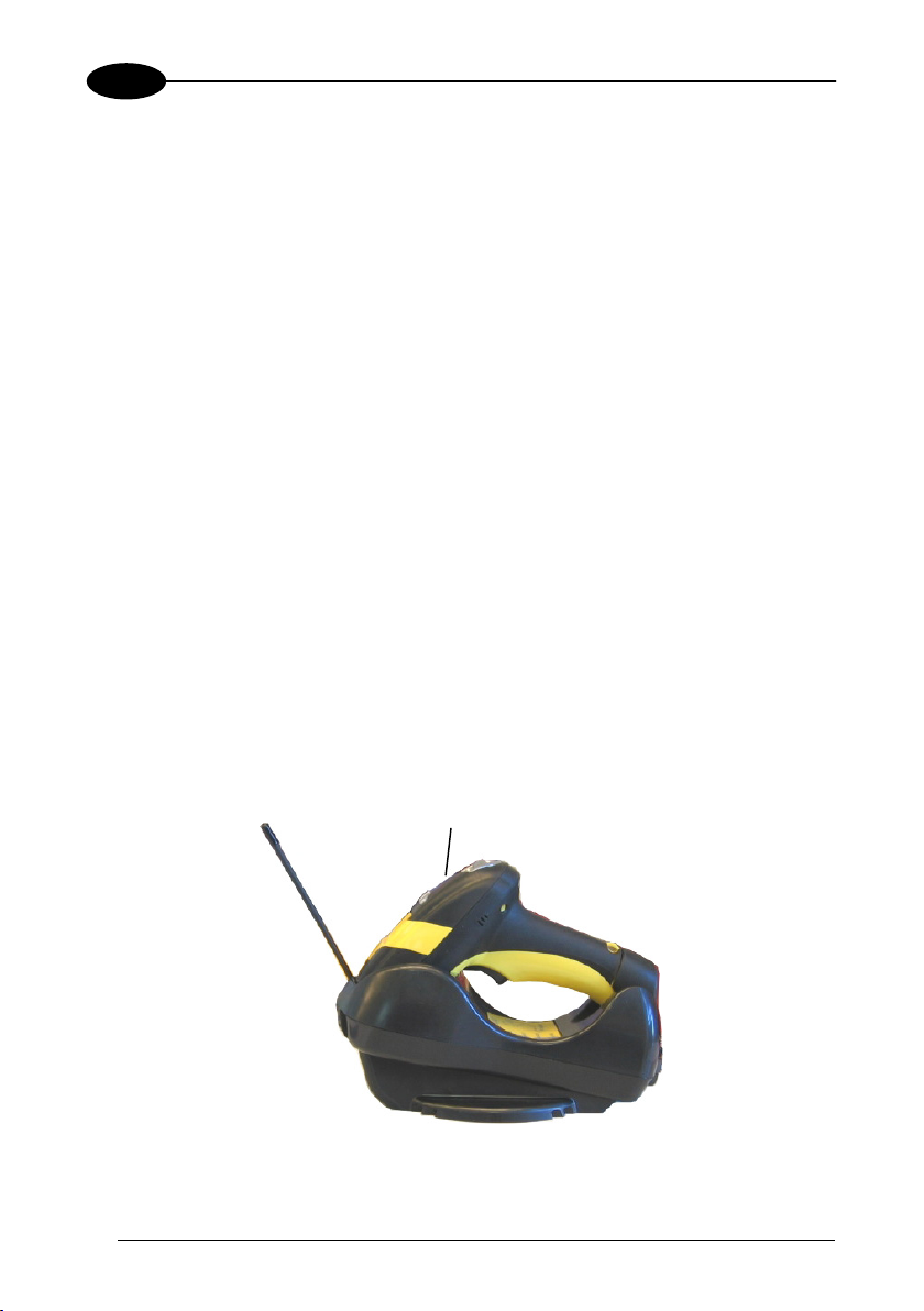
The green LED on the Dragon™ M131 will blink; the reader is ready to be
inserted into the cradle.
Firmly insert the reader into the OM-30X0 cradle within 10 seconds, a beep will
8.
be emitted, signaling that the OM-30X0 cradle has been paired to the
Dragon™ M131, and the green LED on the reader will go off.
Ì$+RN0$-IÎ
Bind
green LED
20
Page 33
CONFIGURATION
Read the OM-30X0 restore default code:
9.
Go to par. 4.8 Interface Selection.
Restore OM-30X0 Default
Ì$+RX0$-qÎ
4
4.5.1 Using Multiple M-Series Readers With Same Cradle
If you want to use several M-Series readers with the same OM-30X0 cradle, you
must first Bind the cradle with one of the readers (see previously described
configuration procedure).
Successive readers
configuration procedure substituting the Bind command with Join (step 7).
7.
can be associated with the same cradle by following the
Join
Ì$+RN1$-NÎ
The green LED on the Dragon™ M131 will blink: the reader is ready to be
positioned onto the cradle. Complete step 8.
END of procedure.
All readers associated with the same cradle must have different
addresses.
CAUTION
YOUR READER IS NOW READY TO READ BARCODES.
To change the defaults see par. 4.10.
21
Page 34

4
DRAGON™ D131/M131
4.5.2 Dragon™ M131/STAR-Modem™ in Stand Alone Mode
To configure a Dragon™ M131 reader to communicate with STAR-Modem™ in
Stand Alone Mode, follow the procedure in par. 4.5 substituting steps 6 and 7 with
those below:
6.
STAR-Modem™ Address
ÌRSRÎ
7.
Read the code above and the four-digit address of the STAR-Modem™.
Exit and Save configuration
Ì$-?Î
END of procedure.
YOUR READER IS NOW READY TO READ BARCODES.
To change the defaults see par. 4.10.
22
Page 35

CONFIGURATION
4
4.6 DRAGON™ M/STAR-SYSTEM™ SETUP
The following procedure allows configuring a Dragon™ M131 reader to communicate
with various STAR-System™ devices such as STARGATE™ RF base stations.
1.
Restore DRAGON™ M131 Default
Ì$+$*oÎ
2.
Enter Configuration
Ì$+;Î
3.
Set Date
ÌIA%Î
+
4.
six digits for Day, Month and Year (DDMMYY)
Set Time
ÌIB'Î
+
Set the connection according to the length of the codes to be read:
5.
four digits for Hour and Minutes (HHMM)
Code Length ≤240 Characters
ÌRA1aÎ
Code Length >240 Characters
(not for systems with OM-3000 as Master)
ÌRA2dÎ
23
Page 36
DRAGON™ D131/M131
6.
4
Set Radio Address
ÌRA0RFHÎ
+
four digits from the Numeric Table in the range 0000-1999.
All readers must have different addresses.
7.
Read the code above and the four-digit address of the First STAR-System™
8.
Read the code above and the four-digit address of the Last STAR-System™
Whenever the system is composed of a single base station, the
first and last base stati
NOTE
the same value.
9.
First STAR-System™ Address
ÌRSRÎ
device in the system.
Set Last STAR-System™ Address
ÌRTTÎ
device in the system.
on addresses (steps 7 and 8) must have
Exit and Save C
onfiguration
Ì$-?Î
END of procedure.
YOUR READER IS NOW READY TO R
To change the defaults see par. 4.10.
EAD BARCODES.
24
Page 37
CONFIGURATION
4
4.7 OM-3000 STAR-SYSTEM™ NETWORK SETUP
When the OM-3000 cradle model is used in an RS485 network, it must be initially
configured. To do this using configuration barcodes, follow the procedure below
using any Dragon™ M131 reader.
1.
Set OM-3000 Address
Ì$+RF4Î
+
four digits for the OM-3000 Address (from 0000 to 1999).
2.
All cradles used in the network must have different addresses.
Exit and Save configuration
Ì$-?Î
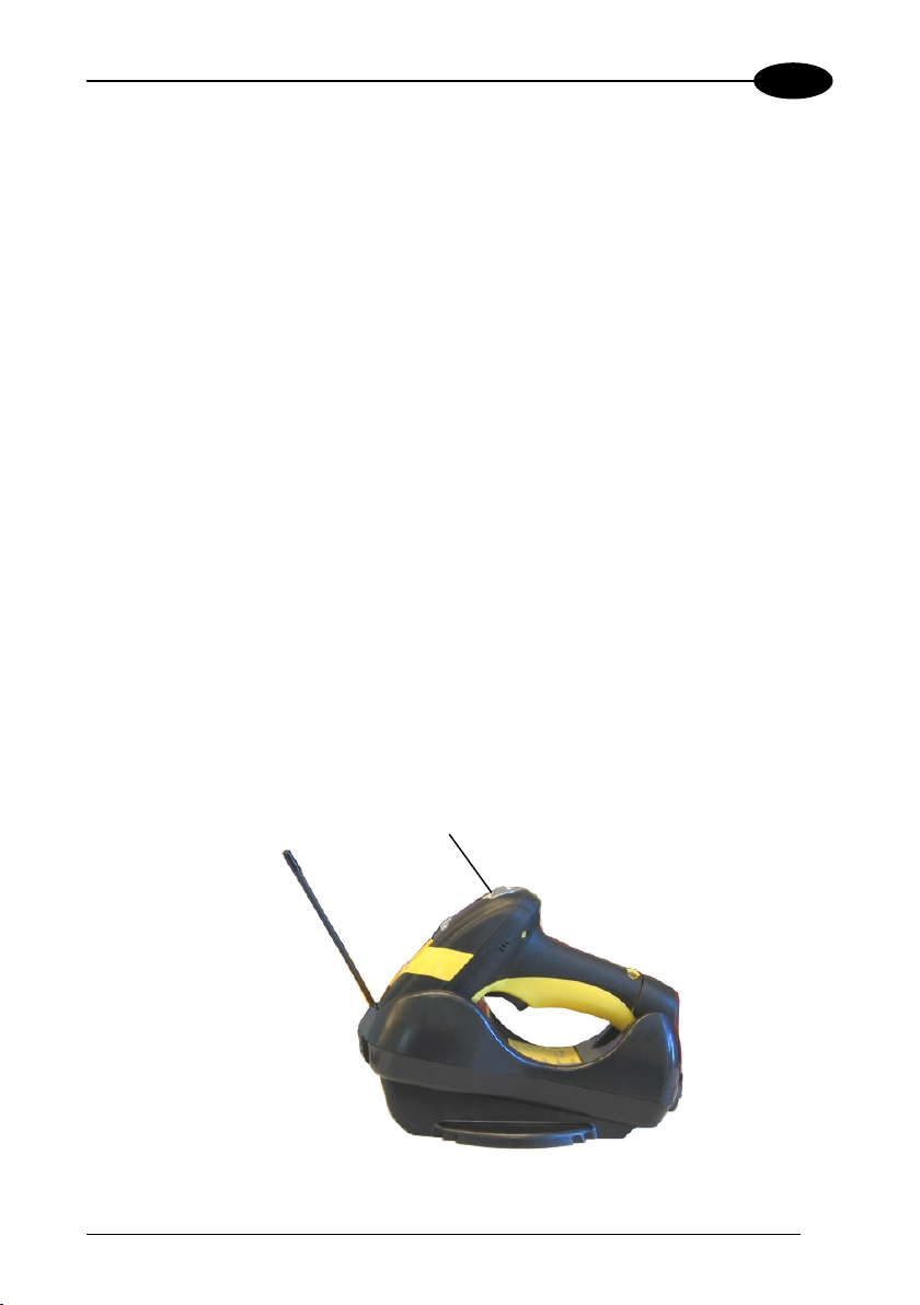
Read the Bind code to pair the Dragon™ M131 to the OM-3000 cradle for
3.
configuration.
The green LED on the Dragon™ M131 will blink; the reader is ready to be
inserted into the cradle.
Firmly insert the reader into the OM-3000 cradle within 10 seconds, a beep
4.
will be emitted, signaling that the OM-3000 cradle has been paired to the
Dragon™ M131, and the green LED on the reader will go off.
green LED
Ì$+RN0$-IÎ
Bind
25
Page 38
4
Read the OM-3000 restore default code:
5.
Read the desired Enable Network code.
6.
Restore OM-3000 Default
Ì$+RX0$-qÎ
Enable RS485 Master
DRAGON™ D131/M131
Ì$+RZ2$-ÇÎ
Enable RS485 Slave
Ì$+RZ1$-~Î
END of procedure.
For Host Master Network Layouts (see par. 3.2), The network configuration
parameters can be changed through STAR-Link™ software running on the PC.
Star-Link™ software can be downloaded for free from the web site:
www.datalogic.com.
For OM-3000 Master Network Layouts (see par. 3.2), The network configuration
parameters can be changed either through the Datalogic Aladdin™ configuration
software running on the PC or by reading the barcode selections in the Network
section of this manual starting on page 57. If using configuration barcodes, it is
advised to completely configure the cradles before reconfiguring the Dragon™ M131
reader (see below).
26
NOTE
After completing the OM-3000 cradle configuration and
connections in the network, you must reconfigure the
Dragon™ M131 reader using the STAR-System™ procedure in
par. 4.6.
Page 39

CONFIGURATION
4.8 INTERFACE SELECTION
Read the interface selection code for your application.
RS232
Standard
Ì$+CP0$-$Î
POS TERMINALS
For POS terminal default settings refer to par. 5.14.
Nixdorf Mode A
Ì$+CM2EC0$->Î
ICL Mode
Ì$+CM0$-ÃÎ
4
Fujitsu
Ì$+CM1$-ÈÎ
PEN
Ì$+CP6$-BÎ
27
Page 40

4
DRAGON™ D131/M131
IBM AT or PS/2 PCs
Ì$+CP500$-aÎ
IBM XT
Ì$+CP503$-vÎ
WEDGE
PC Notebook
Ì$+CP505$-ÈÎ
Ì$+CP506$-$Î
IBM SURE1
IBM Terminal 3153
Ì$+CP504$-}Î
IBM Terminals 31xx, 32xx, 34xx, 37xx:
To select the interface for these IBM Terminals, read the correct KEY TRANSMISSION code.
Select the
KEYBOARD TYPE if necessary (default = advanced keyboard).
KEY TRANSMISSION MODE
make-only keyboard
Ì$+CP502$-oÎ
make-break keyboard
Ì$+CP501$-hÎ
KEYBOARD TYPE
advanced keyboard
Ì$+FK1$-ÉÎ
typewriter keyboard
Ì$+FK0$-ÄÎ
28
Page 41

CONFIGURATION
WEDGE (CONTINUED)
ALT MODE
The ALT-mode selection allows barcodes sent to the PC to be interpreted correctly
independently from the Keyboard Nationality used. You do not need to make a
Keyboard Nationality selection.
(default = Num Lock Unchanged). Make sure the Num Lock key on your
keyboard is ON.
IBM AT - ALT mode
Ì$+CP507$-+Î
ANSI Keyboard
Ì$+CP509$-9Î
ASCII Keyboard
Ì$+CP511$-nÎ
WYSE TERMINALS
PC Notebook - ALT mode
Ì$+CP508$-2Î
PC Keyboard
Ì$+CP510$-gÎ
VT220 style Keyboard
Ì$+CP514$-ÇÎ
4
29
Page 42

4
WEDGE (CONTINUED)
DIGITAL TERMINALS
VT2xx/VT3xx/VT4xx
DRAGON™ D131/M131
Ì$+CP512$-uÎ
APPLE
APPLE ADB Bus
Ì$+CP513$-|Î
30
Page 43
CONFIGURATION
(
)
4
4.9 USB READER CONFIGURATION
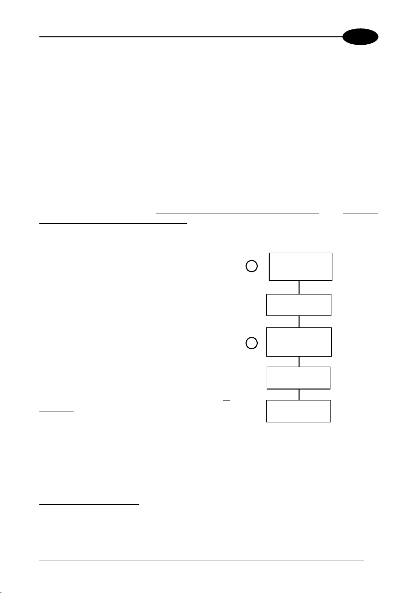
The USB interface is available for Dragon D131, OM-30x0 and C-3000 devices and
is compatible with the following Operating Systems:
Windows 98 (and later) IBM POS for Windows
Mac OS 8.0 (and later) 4690 Operating System
USB Start-up
As with all USB devices, upon connection, the Host performs several checks by
communicating with the device. During this phase normal operations are suspended
(the LED on the Dragon™ D131 reader blinks). Two basic conditions must be met
before the device is ready,
power must be supplied to the reader.
For all systems, the correct USB driver for the
default USB-KBD interface is included in the
Host Operating System and will either be loaded
automatically or will be suggested by the O.S.
and should therefore be selected from the dialog
box (the first time only).
Normally the Host supplies sufficient power to
the device and the start-up phase ends
correctly. (The reader's LED stops blinking and
the reader emits the beep OK signal).
In rare cases, if the Host does not supply
sufficient power to the device, a dialog box will
appear on the Host and the device will be
blocked (the reader's LED continues blinking). In
this case, disconnect the USB device cable
the Host (the reader's LED stops blinking), and
then try a different USB port as indicated by the
Operating System message. (The device emits
the beep OK signal. You can now read codes).
At this point you can read the USB interface configuration code according to your
application. Load drivers from the O.S. (if requested). When configuring the USBCOM interface, the relevant files and drivers must be installed from the USB Device
Installation software which can be downloaded from the web page
http://www.datalogic.com.
The device is ready. Successive start-ups will automatically recognize the previously
loaded drivers.
the correct USB driver must be loaded and sufficient
First Start-Up
Connect device to
1
2
at
Host
reader LED blinks
Load drivers
if requested
reader LED off - BEEP OK
Select desired USB
interface code
(USB-KBD is default)
Load drivers
(if requested)
Read test codes.
Device is READY
31
Page 44

4
USB
USB-KBD
DRAGON™ D131/M131
Ì$+UA03$-:Î
USB-KBD-ALT-MODE
Ì$+UA04$-@Î
USB-KBD-APPLE
Ì$+UA05$-FÎ
USB-COM*
Ì$+UA02$-4Î
USB-IBM-Table Top
Ì$+UA00$-(Î
USB-IBM-Hand Held
Ì$+UA01$-.Î
* When configuring USB-COM, the relevant files and drivers must be installed from
the USB Device Installation software which can be downloaded from the web site
http://www.datalogic.com.
32
Page 45

CONFIGURATION
4
4.10 CHANGING DEFAULT SETTINGS
Once your reader is setup, you can change the default parameters to meet your
application needs. Refer to the preceding paragraphs for initial configuration in order
to set the default values and select the interface for your application.
In this manual, the configuration parameters are divided into logical groups making it
easy to find the desired function based on its reference group.
The first four groups are for Standard Interface parameter configuration for all
Dragon™ D131 series readers and Dragon™ M131/OM-30X0 Stand Alone
configurations only:
RS232
USB
WEDGE
PEN EMULATION
NETWORK PARAMETERS are available only for OM-3000 Network configurations.
The following parameter groups are common to all interface applications:
DATA FORMAT parameters regard the messages sent to the Host system for all
interfaces except Pen Emulation.
POWER SAVE manages overall current consumption in the reading device.
READING PARAMETERS control various operating modes and indicator status
functioning.
DECODING PARAMETERS maintain correct barcode decoding in certain special
reading conditions.
CODE SELECTION parameters allow configuration of a personalized mix of codes,
code families and their options.
ADVANCED FORMATTING PARAMETERS allow code concatenation and
advanced formatting of messages towards the Host. It cannot be used with Pen
Emulation connections.
RADIO PARAMETERS (M131 series only) allow configuration of radio control
parameters.
DISPLAY PARAMETERS (some M131 series models only) allow configuration of
reader display parameters.
33
Page 46

RS232 PARAMETERS
All Dragon™ D131 Series readers
+
Dragon™ M131/OM-30X0 configurations only
BAUD RATE
PARITY
DATA BITS
STOP BITS
HANDSHAKING
ACK/NACK PROTOCOL
FIFO
INTER-CHARACTER DELAY
RX TIMEOUT
SERIAL TRIGGER LOCK
1. Read the Enter Configuration code ONCE, available at the top of each page.
2. Read configuration codes from the desired groups.
= Read the code and follow the procedure given
= Default value
3. Read the Exit and Save Configuration code ONCE, available at the top of
each page.
34
Page 47

Enter Configuration Exit and Save Configuration
Ì$+;Î
BAUD RATE
300 baud
ÌCD1XÎ
1200 baud
ÌCD3^Î
4800 baud
ÌCD5dÎ
19200 baud
ÌCD7jÎ
none
ÌCC0SÎ
odd parity
ÌCC2YÎ
RS232
PARITY
Ì$-?Î
600 baud
ÌCD2[Î
2400 baud
ÌCD4aÎ
9600 baud
ÌCD6gÎ
38400 baud
ÌCD8mÎ
even parity
ÌCC1VÎ
35
Page 48

Enter Configuration Exit and Save Configuration
Ì$+;Î
7 bits
ÌCA0OÎ
9 bits
ÌCA2UÎ
1 stop bit
ÌCB0QÎ
disable
ÌCE0WÎ
software (XON/XOFF)
ÌCE2]Î
RS232
DATA BITS
STOP BITS
HANDSHAKING
See par. 5.1.1 for details.
Ì$-?Î
8 bits
ÌCA1RÎ
2 stop bits
ÌCB1TÎ
hardware (RTS/CTS)
ÌCE1ZÎ
RTS always ON
ÌCE3`Î
36
Page 49

Enter Configuration Exit and Save Configuration
Ì$+;Î
RS232
Ì$-?Î
ACK/NACK PROTOCOL
disable
ÌER0sÎ
See par. 5.1.2 for details, particularly on implementing this parameter with Dragon™ M131.
enable
ÌER1vÎ
FIFO
disable
ÌEC0UÎ
See par. 5.1.3 for details.
enable
ÌEC1XÎ
INTER-CHARACTER DELAY
delay between characters transmitted to Host
ÌCK3Î
Read 2 numbers from the table where:
00 = DELAY disabled
01-99 = DELAY from 1 to 99 milliseconds
delay disabled
37
Page 50

Enter Configuration Exit and Save Configuration
Ì$+;Î
RS232
RX TIMEOUT
timeout control in reception from Host
ÌCL5Î
Read 2 numbers from the table where:
00 = TIMEOUT disabled
01-99 = TIMEOUT from .1 to 9.9 seconds
rx timeout 5 seconds
See par. 5.1.4 for details.
SERIAL TRIGGER LOCK
disabled
ÌCR0qÎ
Read 2 characters from the Hex/Numeric table in the range 00-FE where:
− First Character enables device trigger
− Second Character inhibits device trigger until the first character is received again.
enable and select characters
ÌCR1tÎ
Ì$-?Î
38
Page 51

USB PARAMETERS
Handshaking, Ack/Nack protocol, FIFO,
Inter-character delay, Rx timeout, Serial
Keyboard nationality, FIFO, Inter-character
delay, Inter-code delay, USB keyboard
No parameter selection required.
USB-COM
trigger lock
USB-KBD
speed
USB-IBM
1. Read the Enter Configuration code ONCE, available at the top of each page.
2. Read configuration codes from the desired groups.
= Read the code and follow the procedure given
= Default value
3. Read the Exit and Save Configuration code ONCE, available at the top of
each page.
39
Page 52

Enter Configuration Exit and Save Configuration
Ì$+;Î
USB-COM
Ì$-?Î
HANDSHAKING
disable
ÌCE0WÎ
software (XON/XOFF)
ÌCE2]Î
See par. 5.1.1 for details.
hardware (RTS/CTS)
ÌCE1ZÎ
RTS always ON
ÌCE3`Î
ACK/NACK PROTOCOL
disable
ÌER0sÎ
See par. 5.1.2 for details, particularly on implementing this parameter with Dragon™ M131.
enable
ÌER1vÎ
FIFO
disable
ÌEC0UÎ
See par. 5.1.3 for details.
enable
ÌEC1XÎ
40
Page 53

Enter Configuration Exit and Save Configuration
Ì$+;Î
USB-COM
INTER-CHARACTER DELAY
delay between characters transmitted to Host
ÌCK3Î
Read 2 numbers from the table where:
00 = DELAY disabled
01-99 = DELAY from 1 to 99 milliseconds
delay disabled
RX TIMEOUT
timeout control in reception from Host
ÌCL5Î
Read 2 numbers from the table where:
00 = TIMEOUT disabled
01-99 = TIMEOUT from .1 to 9.9 seconds
rx timeout 5 seconds
See par. 5.1.4 for details.
SERIAL TRIGGER LOCK
disabled
ÌCR0qÎ
Read 2 characters from the Hex/Numeric table in the range 00-FE where:
− First Character enables device trigger
− Second Character inhibits device trigger until the first character is received again.
enable and select characters
ÌCR1tÎ
Ì$-?Î
41
Page 54

Enter Configuration Exit and Save Configuration
Ì$+;Î
USB-KBD
Ì$-?Î
KEYBOARD NATIONALITY
This parameter default value is restored through the Interface Selection code and not Restore
Default.
Belgian
ÌFJ7yÎ
French
ÌFJ2jÎ
Italian
ÌFJ1gÎ
Swedish
ÌFJ5sÎ
Not Available for USB-KBD-ALT-MODE Interface
English
ÌFJ4pÎ
German
ÌFJ3mÎ
Spanish
ÌFJ6vÎ
USA
ÌFJ0dÎ
42
Page 55

Enter Configuration Exit and Save Configuration
Ì$+;Î
The Japanese and Eastern Block Keyboard Nationality selections are valid only for IBM AT
compatible PCs.
Japanese
ÌFJ8|Î
Russian (Cyrillic)
ÌFJA0Î
Slovenian, Croatian,
Serbian (Latin)
ÌFJC6Î
Czech Republic
ÌFJE<Î
USB-KBD
Ì$-?Î
Russian (Latin)
ÌFJ9ÃÎ
Hungarian
ÌFJB3Î
Romanian
ÌFJD9Î
FIFO
disable
ÌEC0UÎ
See par. 5.1.3 for details.
enable
ÌEC1XÎ
43
Page 56

Enter Configuration Exit and Save Configuration
Ì$+;Î
ÌUT10cÎ
USB-KBD
INTER-CHARACTER DELAY
delay between characters transmitted to Host
ÌCK3Î
Read 2 numbers from the table where:
00 = DELAY disabled
01-99 = DELAY from 1 to 99 milliseconds
delay disabled
INTER-CODE DELAY
delay between codes transmitted to Host
ÌFG.Î
Read 2 numbers from the table where:
00 = DELAY disabled
01-99 = DELAY from 1 to 99 seconds
delay disabled
USB KEYBOARD SPEED
Normal
Ì$-?Î
Fast
ÌUT01dÎ
44
Page 57

WEDGE PARAMETERS
All Dragon™ D131 Series readers
+
Dragon™ M131/OM-30X0 configurations only
KEYBOARD NATIONALITY
CAPS LOCK
CAPS LOCK
A
UTO-RECOGNITION
NUM LOCK
INTER-CHARACTER DELAY
INTER-CODE DELAY
KEYBOARD SETTING
W
EDGE CONTROL CHARACTER
EMULATION
1. Read the Enter Configuration code ONCE, available at the top of each page.
2. Read configuration codes from the desired groups.
= Read the code and follow the procedure given
= Default value
3. Read the Exit and Save Configuration code ONCE, available at the top of
each page.
45
Page 58

Enter Configuration Exit and Save Configuration
Ì$+;Î
WEDGE
KEYBOARD NATIONALITY
Belgian
ÌFJ7yÎ
French
ÌFJ2jÎ
Italian
ÌFJ1gÎ
Swedish
ÌFJ5sÎ
Ì$-?Î
English
ÌFJ4pÎ
German
ÌFJ3mÎ
Spanish
ÌFJ6vÎ
USA
ÌFJ0dÎ
46
Page 59

Enter Configuration Exit and Save Configuration
Ì$+;Î
The Japanese and Eastern Block Keyboard Nationality selections are valid only for IBM AT
compatible PCs.
Japanese
ÌFJ8|Î
Russian (Cyrillic)
ÌFJA0Î
Slovenian, Croatian,
Serbian (Latin)
ÌFJC6Î
Czech Republic
ÌFJE<Î
WEDGE
Ì$-?Î
Russian (Latin)
ÌFJ9ÃÎ
Hungarian
ÌFJB3Î
Romanian
ÌFJD9Î
CAPS LOCK
caps lock OFF
ÌFE0ZÎ
Note: Caps lock manual configuration is ignored when Caps Lock Auto-Recognition is
Select the appropriate code to match your keyboard caps lock status.
enabled.
For PC Notebook interface selections, the caps lock status is automatically recognized,
therefore this command is not necessary.
caps lock ON
ÌFE1]Î
47
Page 60

Enter Configuration Exit and Save Configuration
Ì$+;Î
WEDGE
Ì$-?Î
CAPS LOCK AUTO-RECOGNITION (IBM AT COMPATIBLE ONLY)
disable
ÌFP0pÎ
enable
ÌFP1sÎ
NUM LOCK
toggle num lock
ÌFL1kÎ
This selection is used together with the Alt Mode interface selection for AT or Notebook PCs.
It changes the way the Alt Mode procedure is executed, therefore it should be set as follows:
• if your keyboard Num Lock is
• if your keyboard Num Lock is
In this way the device will execute the Alt Mode procedure correctly for your application.
normally on use num lock unchanged
normally off use toggle num lock
num lock unchanged
ÌFL0hÎ
INTER-CHARACTER DELAY
delay between characters transmitted to Host
ÌCK3Î
Read 2 numbers from the table where:
00 = DELAY disabled
01-99 = DELAY from 1 to 99 milliseconds
delay disabled
48
Page 61

Enter Configuration Exit and Save Configuration
Ì$+;Î
WEDGE
Ì$-?Î
INTER-CODE DELAY
delay between codes transmitted to Host
ÌFG.Î
Read 2 numbers from the table where:
00 = DELAY disabled
01-99 = DELAY from 1 to 99 seconds
delay disabled
KEYBOARD SETTING
ALPHANUMERIC KEYBOARD SETTING
The device (reader or cradle) can be used with terminals or PCs with various keyboard types
and nationalities through a simple keyboard setting procedure.
The type of computer or terminal must be selected before activating the keyboard setting
command.
Keyboard setting consists of communicating to the device how to send data corresponding to
the keyboard used in the application. The keys must be set in a specific order.
Press and release a key to set it.
Some characters may require more than one key pressed simultaneously during normal use
(refer to the manual of your PC or terminal for keyboard use). The exact sequence must be
indicated to the reader in this case pressing and releasing the different keys.
Example:
If one has to press the "Shift" and "4" keys simultaneously on the keyboard to transmit the
character "$" to the video, to set the "$", press and release "Shift" then press and release "4".
Each pressed and released key must generate an acoustic signal on the device, otherwise
repress the key. Never press more than one key at the same time, even if this corresponds to
the normal use of your keyboard.
Press "Backspace" to correct a wrong key entry. In this case the device emits 2 beeps.
Note: "CAPS LOCK" and "NUM LOCK" must be off before starting the keyboard setting
procedure. "SHIFT" must be repressed for each character and cannot be substituted by
"CAPS LOCK".
Read the code above.
Press the keys shown in the following table according to their numerical order.
setting the alphanumeric keyboard
ÌFB0TÎ
49
Page 62

Some ASCII characters may be missing as this depends on the type of keyboard: these are
generally particular characters relative to the various national symbologies. In this case:
• The first 4 characters (Shift, Alt, Ctrl, and Backspace) can only be substituted with
• characters can be substituted with other single symbols (e.g. "SPACE") even if not
• characters can be substituted with others corresponding to your keyboard.
The device signals the end of the procedure with 2 beeps indicating the keys have been
registered.
keys not used, or substituted with each other.
included in the barcode set used.
WEDGE
01 : Shift
02 : Alt
03 : Ctrl
04 : Backspace
05 : SPACE 28 : 7 51 : N
06 : ! 29 : 8 52 : O
07 : " 30 : 9 53 : P
08 : # 31 : : 54 : Q
09 : $ 32 : ; 55 : R
10 : % 33 : < 56 : S
11 : & 34 : = 57 : T
12 : ' 35 : > 58 : U
13 : ( 36 : ? 59 : V
14 : ) 37 : @ 60 : W
15 : * 38 : A 61 : X
16 : + 39 : B 62 : Y
17 : , 40 : C 63 : Z
18 : - 41 : D 64 : [
19 : . 42 : E 65 : \
20 : / 43 : F 66 : ]
21 : 0 44 : G 67 : ^
22 : 1 45 : H 68 : _ (underscore)
23 : 2 46 : I 69 : `
24 : 3 47 : J 70 : {
25 : 4 48 : K 71 : |
26 : 5 49 : L 72 : }
27 : 6 50 : M 73 : ~
74 : DEL
CAUTION
50
Do not place the reader onto the OM-30X0 cradle during this procedure.
Otherwise, the battery charging will occur modifying the LEDs functioning.
Page 63

Enter Configuration Exit and Save Configuration
Ì$+;Î
CONTROL CHARACTER EMULATION
Ctrl + Shift + Key
ÌFO0nÎ
WEDGE
Ì$-?Î
Ctrl + Key
ÌFO1qÎ
51
Page 64

PEN EMULATION
All Dragon™ D131 Series readers
+
Dragon™ M131/OM-30X0 configurations only
OPERATING MODE
MINIMUM OUTPUT PULSE
CONVERSION TO CODE 39
OVERFLOW
OUTPUT LEVEL
IDLE LEVEL
INTER-BLOCK DELAY
1. Read the Enter Configuration code ONCE, available at the top of each page.
2. Read configuration codes from the desired groups.
= Default value
3. Read the Exit and Save Configuration code ONCE, available at the top of
each page.
52
Page 65

The operating mode parameters are complete commands and do not require reading the
Enter and Exit configuration codes.
PEN EMULATION
OPERATING MODE
interpret mode
Ì$]8Î
Interprets commands without sending them to the decoder.
transparent mode
Ì$[4Î
Sends commands to the decoder without interpreting them.
53
Page 66
Enter Configuration Exit and Save Configuration
Ì$+;Î
200 µs
ÌDG0\Î
600 µs
ÌDG2bÎ
ÌDG4hÎ
1 ms
PEN EMULATION
Ì$-?Î
MINIMUM OUTPUT PULSE
high resolution code
emulation
400 µs
ÌDG1_Î
800 µs
ÌDG3eÎ
low resolution code
emulation
See par. 5.2.1 for details.
1.2 ms
ÌDG5kÎ
54
Page 67

Enter Configuration Exit and Save Configuration
Ì$+;Î
PEN EMULATION
CONVERSION TO CODE 39 (D131 SERIES ONLY)
disable conversion to
Code 39
ÌDA0PÎ
Transmits codes in their
original format.
enable conversion to Code 39
ÌDA1SÎ
Converts codes read into
Code 39 format.
See par. 5.2.2 for details.
CONVERSION TO CODE 39 AND CODE 128 (M131 SERIES ONLY)
enable conversion to
Code 39
ÌDA1SÎ
Converts codes read into
Code 39 format.
enable conversion to
Code 128
ÌDA0PÎ
Converts codes read into
Code 128 format.
See par. 5.2.2 for details.
OVERFLOW
narrow
ÌDH0^Î
wide
ÌDH2dÎ
See par. 5.2.3 for details.
medium
ÌDH1aÎ
Ì$-?Î
55
Page 68

Enter Configuration Exit and Save Configuration
Ì$+;Î
normal
ÌDD0VÎ
(white = logic level 0)
normal
ÌDE0XÎ
(black level)
PEN EMULATION
OUTPUT LEVEL
(white = logic level 1)
See par. 5.2.4 for details.
IDLE LEVEL
See par. 5.2.4 for details.
INTER-BLOCK DELAY
delay between character blocks transmitted to Host
ÌCK3Î
Read 2 numbers from the table where:
00 = DELAY disabled
01-99 = DELAY from .1 to 9.9 seconds
delay disabled
See par. 5.2.5 for details.
Ì$-?Î
inverted
ÌDD1YÎ
inverted
ÌDE1[Î
(white level)
56
Page 69

NETWORK PARAMETERS
OM-3000 model configurations only
RS485 NETWORK
NETWORK BAUD RATE
SLAVE ADDRESS RANGE
NETWORK WARNING MESSAGE
RECEPTION WARNING
MESSAGE
MASTER CRADLE HEADER
MASTER CRADLE TERMINATOR
1. Read the Enter Configuration code ONCE, available at the top of each page.
2. Read configuration codes from the desired groups.
3. Read the Exit and Save Configuration code ONCE, available at the top of
each page.
57
Page 70
Enter Configuration Exit and Save Configuration
Ì$+;Î
NETWORK PARAMETERS
RS485 NETWORK
disable RS485 network
ÌRZ0)Î
enable RS485 master
ÌRZ2/Î
NOTE
If an OM-3000 cradle is errantly configured as a Slave but not connected to
a network, it may not be able to receive further commands from the gun. In
this case it can be reconfigured by executing the bind procedure, which
returns the cradle to Stand Alone configuration.
9600
ÌJE0^Î
38400
ÌJE2dÎ
See par. 3.2 for details.
ETWORK AUD ATEN B R
Ì$-?Î
enable RS485 slave
ÌRZ1,Î
19200
ÌJE1aÎ
58
Page 71

Enter Configuration Exit and Save Configuration
Ì$+;Î
NETWORK PARAMETERS
Ì$-?Î
SLAVE ADDRESS RANGE
Read the code above and the four-digit address of the First Slave device in the system.
Read the code above and the four-digit address of the Last Slave device in the system.
First Address
ÌJB(Î
Last Address
ÌJC*Î
See par. 5.3.1 for details.
NETWORK WARNING MESSAGE
network warning
message not transmitted
ÌJG0bÎ
See par. 5.3.2 for details.
network warning message
transmitted
ÌJG1eÎ
RECEPTION WARNING MESSAGE
reception warning message
not transmitted
ÌJH0dÎ
See par. 5.3.3 for details.
reception warning
message transmitted
ÌJH1gÎ
59
Page 72

Enter Configuration Exit and Save Configuration
Ì$+;Î
NETWORK PARAMETERS
Ì$-?Î
MASTER CRADLE HEADER
two character header
four character header
eight character header
no header
ÌJA00/Î
ÌJA027Î
ÌJA04?Î
six character header
ÌJA06GÎ
ÌJA08OÎ
one character header
ÌJA013Î
three character header
ÌJA03;Î
five character header
ÌJA05CÎ
seven character header
ÌJA07KÎ
After selecting one of the desired Header codes, read the character(s) from the HEX table.
Example:
For more details about default and WEDGE Interface Extended Keyboard values, see
par. 5.3.4, 5.4.1 and 5.4.2.
Valid characters are in the range: 00-FE
four character header
+ 41 + 42 + 43 + 44 = Header ABCD
60
Page 73

Enter Configuration Exit and Save Configuration
Ì$+;Î
NETWORK PARAMETERS
Ì$-?Î
MASTER CRADLE TERMINATOR
two character terminator
four character terminator
six character terminator
eight character terminator
no terminator
ÌJA102Î
ÌJA12:Î
ÌJA14BÎ
ÌJA16JÎ
ÌJA18RÎ
one character terminator
ÌJA116Î
three character terminator
ÌJA13>Î
five character terminator
ÌJA15FÎ
seven character terminator
ÌJA17NÎ
After selecting one of the desired Terminator codes, read the character(s) from the HEX table.
Example:
For more details about default and WEDGE Interface Extended Keyboard values, see
par. 5.3.4, 5.4.1 and 5.4.2.
Valid characters are in the range: 00-FE
two character ter minator
+ 0D + 0A = Terminator CR LF
61
Page 74

DATA FORMAT
NOT FOR PEN INTERFACES
CODE IDENTIFIER
CUSTOM CODE IDENTIFIER
HEADER
TERMINATOR
SPECIAL KEYS
FIELD ADJUSTMENT
FIELD ADJ. CHARACTER
CODE LENGTH TX
CHARACTER REPLACEMENT
ADDRESS STAMPING
ADDRESS DELIMITER
TIME STAMPING
TIME DELIMITER
1. Read the Enter Configuration code ONCE, available at the top of each page.
2. Read configuration codes from the desired groups.
= Read the code and follow the procedure given
= Default value
3. Read the Exit and Save Configuration code ONCE, available at the top of
each page.
62
Page 75

DATA FORMAT
CODE IDENTIFIER TABLE
CODE AIM STANDARD DATALOGIC STANDARD Custom
2/5 interleaved ] I y N
2/5 industrial ] X y P
2/5 normal 5 bars ] S y O
2/5 matrix 3 bars ] X y Q
EAN 8 ] E 4 A
EAN 13 ] E 0 B
UPC A ] X y C
UPC E ] X y D
EAN 8 with 2 ADD ON ] E 5 J
EAN 8 with 5 ADD ON ] E 6 K
EAN 13 with 2 ADD ON ] E 1 L
EAN 13 with 5 ADD ON ] E 2 M
UPC A with 2 ADD ON ] X y F
UPC A with 5 ADD ON ] X y G
UPC E with 2 ADD ON ] X y H
UPC E with 5 ADD ON ] X y I
Code 39 ] A y V
Code 39 Full ASCII ] A y W
CODABAR ] F y R
ABC CODABAR ] X y S
Code 128 ] C y T
EAN 128 ] C y k
ISBT 128
Code 93 ] G y U
CIP/39 ] X y Y
CIP/HR ] X y e
Code 32 ] X y X
MSI ] M y Z
Code 11 ] H y b
Code 16K ] K 0 p
Code 49 ] T y q
RSS Expanded Linear and Stacked ] e 0 t
RSS Limited ] e 0 v
RSS 14 Linear and Stacked ] e 0 u
• AIM standard identifiers are not defined for all codes: the X identifier is assigned to the
code for which the standard is not defined. The y value depends on the selected options
(check digit tested or not, check digit tx or not, etc.).
• When customizing the Datalogic Standard code identifiers, 1 or 2 identifier characters can
be defined for each code type. If only 1 identifier character is required, the second character
must be selected as FF (disabled).
• The code identifier can be singly disabled for any code by simply selecting FF as the first
identifier character.
• Write in the Custom character identifiers in the table above for your records.
] C4 f
63
Page 76

Enter Configuration Exit and Save Configuration
Ì$+;Î
DATA FORMAT
Ì$-?Î
CODE IDENTIFIER
disable
ÌEB0SÎ
AIM standard
ÌEB2YÎ
Datalogic standard
ÌEB1VÎ
custom
ÌEB3\Î
CUSTOM CODE IDENTIFIER
Read the above code.
(Code Identifiers default to Datalogic standard, see table on previous page).
Select the code type from the code table in Appendix
change.
You can define 1 or 2 identifier characters for each code type. If only 1 identifier character is
required, the second character must be selected as FF (disabled). Read the hexadecimal
value corresponding to the character(s) you want to define as identifiers for the code
selected in step : valid characters are in the range 00-FD.
Example: To define Code 39 Code Identifier = @
Read
define custom code identifier(s)
define custom code identifier(s)
ÌEH/Î
ÌEH/Î
+
B for the identifier you want to
Code 39
ÌVWÎ
+ 40 + FF
64
Page 77

Enter Configuration Exit and Save Configuration
Ì$+;Î
DATA FORMAT
Ì$-?Î
HEADER
no header
ÌEA00*Î
two character header
ÌEA022Î
four character header
ÌEA04:Î
six character header
ÌEA06BÎ
eight character header
ÌEA08JÎ
one character header
ÌEA01.Î
three character header
ÌEA036Î
five character header
ÌEA05>Î
seven character header
ÌEA07FÎ
After selecting one of the desired Header codes, read the character(s) from the HEX table.
Valid characters are in the range 00-FE. For Wedge and USB-KBD interfaces, it is also possible
to read the Special Key(s) on page 67.
Example:
For more details see par. 5.4.1 and par. 5.4.2.
four character header
+ 41 + 42 + 43 + 44 = Header ABCD
65
Page 78

Enter Configuration Exit and Save Configuration
Ì$+;Î
DATA FORMAT
Ì$-?Î
TERMINATOR
no terminator
ÌEA10-Î
two character terminator
ÌEA125Î
four character terminator
ÌEA14=Î
six character terminator
ÌEA16EÎ
eight character terminator
ÌEA18MÎ
one character terminator
ÌEA111Î
three character terminator
ÌEA139Î
five character terminator
ÌEA15AÎ
seven character terminator
ÌEA17IÎ
After selecting one of the desired Header codes, read the character(s) from the HEX table.
Valid characters are in the range 00-FE. For Wedge and USB-KBD interfaces, it is also possible
to read the Special Key(s) on page 67.
Example:
For more details see par. 5.4.1 and par. 5.4.2.
two character terminator
+ 0D + 0A = Terminator CR LF
66
Page 79

Enter Configuration Exit and Save Configuration
Ì$+;Î
DATA FORMAT
SPECIAL KEYS
NOTE
Select one or win according to yo r
Available only for Wedge IBM AT-PS/2 and USB-KBD Interfaces
It is necess
par. 5.4.2.
more of the follo g Special Keys u needs.
Special Key
Ì9CÄÎ
ary to define each Special Key by following the procedure given in
1
Special Key
Ì9EÈÎ
3
Special Key
ÌA0bÎ
5
Ì$-?Î
Special Key
Ì9DÆÎ
Special Key
Ì9FÊÎ
2
4
67
Page 80

Enter Configuration Exit and Save Configuration
Ì$+;Î
DATA FORMAT
Ì$-?Î
FIELD ADJUSTMENT
disable field adjustment
ÌEF0[Î
Field adjustment allows a number of characters n, to be added to or subtracted from the
barcode read. The adjustment can be different for each enabled code type. To
adjustment:
define the field
Read the enable field adjustment code:
enable field adjustment
ÌEF+Î
Select the code type from the Code Identifier Table in Appendix B.
Select the type of adjustment to perform:
right addition
Ì01Î
right deletion
Ì23Î
Read a number in the range 01 - 32 from the Hex/Numeric Table to define how many
characters to add or delete:
Conditions:
• Adjustment is only performed on the barcode data, the Code Identifier and Code Length
Transmission fields are not modified by the field adjustment parameter.
• If the field setting would subtract more characters than exist in the barcode, the subtraction
will take place only to code length 0.
• You can set up to a maximum of 10 different field adjustments on the same barcode family
or on different barcode families.
Example: To add 4 characters to the right of Standard Code 39 Codes:
Read
enable field adjustment
ÌEF+Î
+
Code 39
ÌVWÎ
+
right addition
Ì01Î
left addition
Ì12Î
left deletion
Ì34Î
+ 04
68
Page 81

Enter Configuration Exit and Save Configuration
Ì$+;Î
DATA FORMAT
Ì$-?Î
FIELD ADJUSTMENT CHARACTER
Read the field adjustment character code:
field adjustment character
ÌEG-Î
Read the hexadecimal value corresponding to the character you want to use for field
adjustment. Valid characters are in the range 00-FE. For Wedge and USB-KBD interfaces, it
is also possible to read the Special Key(s) on page 67.
Example:
To define the field adjustment character = A:
field adjustment character
Read
CODE LENGTH TX
code length not transmitted
ÌEE0YÎ
code length transmitted in variable-digit format
ÌEE1\Î
code length transmitted in fixed 4-digit format
ÌEE2_Î
The code length is transmitted in the message after the Headers and Code Identifier characters.
The code length is calculated after performing any field adjustment operations.
+ 41
69
Page 82

Enter Configuration Exit and Save Configuration
Ì$+;Î
DATA FORMAT
Ì$-?Î
CHARACTER REPLACEMENT
disable character replacement
ÌEO0mÎ
This parameter allows up to three characters to be replaced from the barcode read. These
substitutions are stored in memory. To
Read one of the following character replacement codes:
first character replacement
define each character replacement:
ÌEO1pÎ
second character replacement
ÌEO2sÎ
third character replacement
ÌEO3vÎ
From the Code Identifier Table in Appendix B, read the Code Identifier for the desired
code family.
0 = character replacement will be effective for all code families.
From the Hex/Numeric Table read two characters corresponding to the Hex value (00-FE)
which identifies the character to be replaced. For Wedge and USB-KBD interfaces, it is
also possible to read the Special Key(s) on page 67.
From the Hex/Numeric Table read two characters corresponding to the Hex value (00-FE)
which identifies the new character to replace. For Wedge and USB-KBD interfaces, it is
also possible to read the Special Key(s) on page 67.
FF = the character to be replaced will be substituted with no character, that is, it will be
removed from the code.
70
Page 83

Enter Configuration Exit and Save Configuration
Ì$+;Î
DATA FORMAT
Ì$-?Î
Example:
The following strings define:
1. First Character Replacement: substitution in Code 39 barcodes of all occurrences of the 0
character with the 1 character.
2. Second Character Replacement: substitution in Code 39 barcodes of all occurrences of
the A character with the B character.
first character replacement
ÌEO1pÎ
For Code 39 codes containing the string "0123", the contents transmitted will be "1123".
second character
replacement
+
Code 39
ÌVWÎ
Code 39
ÌEO2sÎ + ÌVWÎ
For Code 39 codes containing the string "ABCD", the contents transmitted will be "BBCD".
ASCII characters corresponding
to the HEX value for character 0
+ 30 + 31
ASCII characters corresponding
to the HEX value for character A
+ 41 + 42
ASCII characters corresponding
to the HEX value for character 1
ASCII characters corresponding
to the HEX value for character B
71
Page 84

Enter Configuration Exit and Save Configuration
Ì$+;Î
DATA FORMAT
Ì$-?Î
ADDRESS STAMPING (M131 SERIES ONLY)
disable reader address stamping
enable reader address stamping
ÌRU0ÊÎ
ÌRU1"Î
See par. 5.4.3 for details.
disable cradle address stamping
enable cradle address stamping
ÌRW0#Î
ÌRW1&Î
ADDRESS DELIMITER (M131 SERIES ONLY)
disable cradle address delimiter
enable cradle address delimiter and
ÌRY0'Î
select characters
ÌRY1*Î
disable reader address delimiter
ÌRV0!Î
enable reader address delimiter and
select characters
ÌRV1$Î
Read 2 HEX characters in the range 00-FE. Read 2 HEX characters in the range 00-FE.
See par. 5.4.4 for details.
72
Page 85

Enter Configuration Exit and Save Configuration
Ì$+;Î
DATA FORMAT
Ì$-?Î
TIME STAMPING (M131 SERIES ONLY)
disable
ÌIL0kÎ
hour/minutes/seconds
day/month/year
ÌIL2qÎ
month/day/year
ÌIL4wÎ
See par. 5.4.5 for details.
hour/minutes/seconds
month/day/year
ÌIL1nÎ
hour/minutes/seconds
ÌIL3tÎ
day/month/year
ÌIL5zÎ
TIME STAMPING DELIMITER (M131 SERIES ONLY)
disable
ÌIM0mÎ
select delimiter
ÌIM1pÎ
See par. 5.4.6 for details.
Read 2 HEX characters in the range 00-FE.
73
Page 86

POWER SAVE
SLEEP STATE
ENTER SLEEP TIMEOUT
1. Read the Enter Configuration code ONCE, available at the top of each page.
2. Read configuration codes from the desired groups.
= Read the code and follow the procedure given
= Default value
3. Read the Exit and Save Configuration code ONCE, available at the top of
each page.
74
Page 87

Enter Configuration Exit and Save Configuration
Ì$+;Î
POWER SAVE
Ì$-?Î
SLEEP STATE
For M131 series readers, sleep state is entered immediately after reading a code and is not
configurable.
disable
ÌBQ0nÎ
See par. 5.5.1 for details.
enable
ÌBQ1qÎ
ENTER SLEEP TIMEOUT
Read 2 numbers in the range 00-99:
00 = Enter Sleep state immediately
01-99 = corresponds to a max. 9.9 sec. delay before entering the
enter sleep timeout = 0.6 sec.
enter sleep timeout
ÌBR@Î
Sleep state.
See par. 5.5.2 for details.
75
Page 88

READING PARAMETERS
GOOD READ SPOT DURATION
TRIGGER TYPE
TRIGGER SIGNAL
TRIGGER CLICK
TRIGGER-OFF TIMEOUT
FLASH MODE
READS PER CYCLE
SAFETY TIME
BEEPER INTENSITY
BEEPER TONE
BEEPER TYPE
BEEPER LENGTH
AIMING SYSTEM
CRADLE BEEPER INTENSITY
1. Read the Enter Configuration code ONCE, available at the top of each page.
2. Read configuration codes from the desired groups.
= Read the code and follow the procedure given
= Default value
3. Read the Exit and Save Configuration code ONCE, available at the top of
76
each page.
Page 89

Enter Configuration Exit and Save Configuration
Ì$+;Î
hardware trigger
ÌBK1eÎ
Restores TRIGGER MODE
always on
ÌBK3kÎ
trigger active level
ÌBA0NÎ
disable
ÌBc0+Î
READING PARAMETERS
TRIGGER TYPE
TRIGGER SIGNAL
See par. 5.6.1 for details.
TRIGGER CLICK
See par. 5.6.2 for details.
Ì$-?Î
software trigger
ÌBK0bÎ
Enables FLASH MODE
trigger active pulse
ÌBA1QÎ
enable
ÌBc1.Î
77
Page 90

Enter Configuration Exit and Save Configuration
Ì$+;Î
one read per cycle
ÌBC0RÎ
READING PARAMETERS
Ì$-?Î
TRIGGER-OFF TIMEOUT
trigger-off timeout
ÌBD$Î
Read 2 numbers in the range 00-99:
00 = disables the trigger-off timeout
01-99 = corresponds to a max. 99-sec. delay after the trigger
trigger-off timeout disabled
press to allow the reader to turn off automatically.
See par. 5.6.3 for details.
FLASH MODE
"FLASH" ON duration
ÌBB0PÎ
"FLASH" OFF duration
ÌBB1SÎ
Read 2 numbers in the range 01-99:
01 to 99 = from .1 to 9.9 seconds.
Flash-ON = 1 sec. Flash-OFF = 0.6 sec
READS PER CYCLE
See par. 5.6.4 for details.
multiple reads per cycle
ÌBC1UÎ
78
Page 91

Enter Configuration Exit and Save Configuration
Ì$+;Î
READING PARAMETERS
Ì$-?Î
SAFETY TIME
Limits
Read 2 numbers in the range 00-99:
00 = no same code consecutive reading until reader is
01-99 = timeout from .1 to 9.9 seconds before a consecutive read
safety time = 0.5 sec
safety time
ÌBE&Î
same code consecutive reading.
removed (no decoding) for at least 400 ms.
on same code.
See par. 5.6.5 for details.
BEEPER INTENSITY
* very low intensity
ÌBG0ZÎ
medium intensity
ÌBG2`Î
* This sets the beeper OFF for data entry, while for all other beeper signals it has the
meaning “very low intensity”. The Beeper Intensity parameter is effective for all operating
conditions described in par. 7.5.
low intensity
ÌBG1]Î
high intensity
ÌBG3cÎ
79
Page 92

Enter Configuration Exit and Save Configuration
Ì$+;Î
tone 1
ÌBH0\Î
tone 3
ÌBH2bÎ
monotone
ÌBJ0`Î
long
ÌBI0^Î
READING PARAMETERS
Ì$-?Î
BEEPER TONE
tone 2
ÌBH1_Î
tone 4
ÌBH3eÎ
BEEPER TYPE
bitonal
ÌBJ1cÎ
BEEPER LENGTH
short
ÌBI1aÎ
80
Page 93

Enter Configuration Exit and Save Configuration
Ì$+;Î
ÌBV0xÎ
ÌBV2~Î
disabled
ÌBj09Î
ÌJI0fÎ
medium intensity
ÌJI2lÎ
READING PARAMETERS
Ì$-?Î
GOOD READ SPOT DURATION
disable
short
ÌBV1{Î
long
ÌBV3ÅÎ
medium
AIMING SYSTEM
enabled
ÌBj1<Î
CRADLE BEEPER INTENSITY
disable
low intensity
ÌJI1iÎ
high intensity
ÌJI3oÎ
81
Page 94
DECODING PARAMETERS
CAUTION
Before changing these parameter values read the descriptions in
par. 5.7.
INK SPREAD
OVERFLOW CONTROL
INTERDIGIT CONTROL
DECODING SAFETY
PUZZLE SOLVER™
1. Read the Enter Configuration code ONCE, available at the top of each page.
2. Read configuration codes from the desired groups.
= Default value
3. Read the Exit and Save Configuration code ONCE, available at the top of
each page.
82
Page 95

Enter Configuration Exit and Save Configuration
Ì$+;Î
disable
ÌAX0{Î
disable
ÌAW1|Î
disable
ÌAV0wÎ
DECODING PARAMETERS
Ì$-?Î
INK SPREAD
See par. 5.7.1 for details.
enable
ÌAX1~Î
OVERFLOW CONTROL
See par. 5.7.2 for details.
enable
ÌAW0yÎ
INTERDIGIT CONTROL
See par. 5.7.3 for details.
enable
ÌAV1zÎ
83
Page 96

Enter Configuration Exit and Save Configuration
Ì$+;Î
DECODING PARAMETERS
Ì$-?Î
DECODING SAFETY
one read
ÌED0WÎ
(decoding safety disabled)
three reads
ÌED2]Î
Required number of good reads before accepting code.
two reads
ÌED1ZÎ
four reads
ÌED3`Î
PUZZLE SOLVER™
In the case of damaged or poorly printed codes, this parameter allows reading multiple parts of
the single code to reconstruct it.
To read codes using this technology, simply move the illuminated bar over the code so that
each line of the code is scanned. During this process a series of brief “ticks” indicates that
reading is proceeding correctly.
Conditions:
• This parameter is only valid for the following codes:
• For Code 39, Check digit control is forced.
• PuzzleSolver™ is not valid for ISBT 128 code.
disable
ÌAU0uÎ
without Add-on
EAN 8
Code 128 Code 39
EAN 13
without Add-on
UPC A
without Add-on
enable
ÌAU1xÎ
84
Page 97

CODE SELECTION
AUTO-CONFIGURATION
EAN/UPC FAMILY
2/5 FAMILY
CODE 39 FAMILY
CODE 128 FAMILY
CODABAR FAMILY
CODE 93
MSI
CODE 11
CODE 16K
CODE 49
RSS CODES
1. Read the Enter Configuration code ONCE
, available at the top of each page.
2. Read configuration codes from the desired groups.
= Read the code and follow the procedure given
= Default value
3. Read the Exit and Save Configuration code ONCE
each page.
, available at the top of
85
Page 98
Code selections may be performed according to two different procedures:
- Auto-configuration, allowing an automatic recognition and selection of the code families
to be read;
- Manual configuration, requiring configuration and selection of each code family to be
read.
AUTO-CONFIGURATION
The following codes do not require reading the Enter and Exit configuration codes.
In auto-configuration mode the reader enters a particular state, during which it reads,
recognizes and saves all information received from the decoding of an existing code (with the
exception of MSI, Code 49 and Code 16k code types). In this way, the code families will be
automatically configured.
It is possible to configure up to 10 code types, whose length is variable and check digit ignored.
If reading different codes belonging to the same family, information about the last code will
overwrite the information about the previous one.
Follow the given procedure to auto-configure the desired code families:
If no code is read during the auto-configuration procedure (step
configuration will be empty and therefore the reader will be unable to read
CAUTION
Read the following code to enter the auto-configuration mode:
Read an existing code belonging to the code families that you need to configure.
Read the following code to save the configuration automatically and return to the reader's
normal functioning:
codes.
auto-configuration
Ì#+AUTOWÎ
save auto-configuration
), the
Ì$-?Î
If you need to change the configuration, repeat the auto-configuration procedure, follow the
manual configuration by setting the parameters for each single code family or read the "Restore
Default" code on page 154. Be careful that in the latter case all reader parameters will be
restored.
86
Page 99
Enter Configuration Exit and Save Configuration
Ì$+;Î
CODE SELECTION
DISABLE ALL CODE FAMILIES
ÌAZ0ÃÎ
The reader allows up to 10 code selections. This does n
CODES enabled to 10, as it depends on the code family.
NOTE
SINGLE
SELECTIONS =
• ONE combination code from the EAN family
• ONE code
from the 2/5 family
Example
5 code selections: 1.
2. 2/5 Industrial
3. Code 128 + EAN 128
4. Code 39
6.
2/5 Interleaved
UPC A/UPC E
5.
etc.
Full ASCII + Code 32
In this section all SINGLE code selections are underlined and in bold.
ot limit the number of
Ì$-?Î
87
Page 100

Enter Configuration Exit and Save Configuration
Ì$+;Î
CODE SELECTION
Ì$-?Î
EAN/UPC FAMILY
disable the family
ÌAA0MÎ
Read the desired family code
Note:
Since the EAN/UPC without ADD ON code selection is enabled by default, to correctly enable
another selection, first disable the family.
EAN 8/EAN 13/UPC A/UPC E with and without ADD ON
ÌAA8eÎ
WITHOUT ADD ON
EAN 8/EAN 13/UPC A/UPC E
ÌAA1PÎ
UPC A/UPC E
ÌAA4YÎ
EAN 8/EAN 13/UPC A/UPC E
ÌAA5\Î
UPC A/UPC E
ÌAA7bÎ
WITH ADD ON 2 AND 5
EAN 8/EAN 13
ÌAA3VÎ
EAN 8/EAN 13
ÌAA6_Î
88
 Loading...