

Page 1
C-BOX 200
Installation Manual
Page 2

Datalogic Automation S.r.l.
Via S. Vitalino 13
40012 - Lippo di Calderara di Reno
Bologna - Italy
C-BOX 200
Ed.: 07/2007
ALL RIGHTS RESERVED
Datalogic reserves the right to make modifications and improvements without prior notification.
Datalogic shall not be liable for technical or editorial errors or omissions contained herein, nor for incidental or
consequential damages resulting from the use of this material.
Product names mentioned herein are for identification purposes only and may be trademarks and or
registered trademarks of their respective companies.
© Datalogic Automation S.r.l. 2001-2007
821000562 (Rev. B)
Page 3

CONTENTS
SAFETY PRECAUTIONS............................................................................ iv
Power Supply................................................................................................iv
CE Compliance .............................................................................................iv
WEEE Compliance .......................................................................................iv
GENERAL VIEW ......................................................................................... vi
GUIDE TO INSTALLATION ......................................................................viii
1 INTRODUCTION .......................................................................................... 1
1.1 Product Description....................................................................................... 1
2 INSTALLATION............................................................................................ 2
2.1 Package Contents......................................................................................... 2
2.2 Opening the Device ...................................................................................... 3
2.3 Mechanical Installation.................................................................................. 4
2.4 Electrical Connections and Hardware Setup................................................. 6
2.4.1 System Wiring............................................................................................... 8
2.4.2 Power Supply.............................................................................................. 10
2.4.3 Scanner Chassis Grounding Jumper Settings ............................................ 11
2.4.4 Multidrop Address Selection ....................................................................... 11
2.4.5 RS485 Bus Termination.............................................................................. 12
2.4.6 OM4000 Jumper Settings ........................................................................... 12
2.5 9-Pin Internal Connector ............................................................................. 13
2.6 Scanner Requirements ............................................................................... 14
2.7 Operating Modes ........................................................................................ 14
2.7.1 GET/SEND Buttons .................................................................................... 15
2.7.2 LED Indicators ............................................................................................ 16
2.8 Scanner Replacement ................................................................................ 17
3 TECHNICAL FEATURES........................................................................... 18
iii
Page 4
SAFETY PRECAUTIONS
POWER SUPPLY
ATTENTION: READ THIS INFORMATION BEFORE INSTALLING THE PRODUCT
- This product is intended to be installed by Qualified Personnel only.
The C-BOX 200 is intended to be supplied either by a UL Listed NEC Class 2 power
source, or a UL Listed ITE Limited Power Source (LPS), rated 10-30 V dc, minimum
0.65 A.
The overall value of power consumption of the system (C-BOX
200 + scanner) is given by adding the scanner power
consumption to that of the C-BOX 200. Refer to the manual of
CAUTION
See par. 2.4.2 for correct power supply connections.
CE COMPLIANCE
Warning: This is a Class A product. In a domestic environment this product may
cause radio interference in which case the user may be required to take adequate
measures.
WEEE COMPLIANCE
the connected scanner for details about minimum/maximum
supply voltage and power consumption.
Information for the user in accordance with the European Commission Directive 2002/96/EC
At the end of its useful life, the product marked with the crossed out wheeled wastebin must be disposed of separately
from urban waste.
Disposing of the product according to this Directive:
• avoids potentially negative consequences to the environment and human health which otherwise could be
caused by incorrect disposal
• enables the recovery of materials to obtain a significant savings of energy and resources.
For more detailed information about disposal, contact the supplier that provided you with the product in question or
consult the dedicated section at the website www.automation.datalogic.com.
iv
ENGLISH
Page 5

ITALIANO
Informazione degli utenti ai sensi della Direttiva Europea 2002/96/EC
L’apparecchiatura che riporta il simbolo del bidone barrato deve essere smaltita, alla fine della sua vita utile,
separatamente dai rifiuti urbani.
Smaltire l’apparecchiatura in conformità alla presente Direttiva consente di:
• evitare possibili conseguenze negative per l’ambiente e per la salute umana che potrebbero invece
essere causati dall’errato smaltimento dello stesso;
• recuperare materiali di cui è composto al fine di ottenere un importante risparmio di energia e di risorse.
Per maggiori dettagli sulle modalità di smaltimento, contattare il Fornitore dal quale è stata acquistata
l’apparecchiatura o consultare la sezione dedicata sul sito www.automation.datalogic.com.
Benutzerinformation bezüglich Richtlinie 2002/96/EC der europäischen Kommission
Am Ende des Gerätelebenszyklus darf das Produkt nicht über den städtischen Hausmüll entsorgt werden. Eine
entsprechende Mülltrennung ist erforderlich.
Beseitigung des Produkts entsprechend der Richtlinie:
• verhindert negative Auswirkungen für die Umwelt und die Gesundheit der Menschen
• ermöglicht die Wiederverwendung der Materialien und spart somit Energie und Resourcen
Weitere Informationen zu dieser Richtlinie erhalten sie von ihrem Lieferanten über den sie das Produkt erworben
haben, oder besuchen sie unsere Hompage unter www.automation.datalogic.com.
Information aux utilisateurs concernant la Directive Européenne 2002/96/EC
Au terme de sa vie utile, le produit qui porte le symbole d'un caisson à ordures barré ne doit pas être éliminé avec les
déchets urbains.
Éliminer ce produit selon cette Directive permet de:
• éviter les retombées négatives pour l'environnement et la santé dérivant d'une élimination incorrecte
• récupérer les matériaux dans le but d'une économie importante en termes d'énergie et de ressources
Pour obtenir des informations complémentaires concernant l'élimination, veuillez contacter le fournisseur auprès
duquel vous avez acheté le produit ou consulter la section consacrée au site Web www.automation.datalogic.com.
Información para el usuario de accuerdo con la Directiva Europea 2002/96/CE
Al final de su vida útil, el producto marcado con un simbolo de contenedor de bassura móvil tachado no debe
eliminarse junto a los desechos urbanos.
Eliminar este producto de accuerdo con la Directiva permite de:
• evitar posibles consecuencias negativas para el medio ambiente y la salud derivadas de una eliminación
inadecuada
• recuperar los materiales obteniendo así un ahorro importante de energía y recursos
Para obtener una información más detallada sobre la eliminación, por favor, póngase en contacto con el proveedor
donde lo compró o consultar la sección dedicada en el Web site www.automation.datalogic.com.
DEUTSCH
FRANÇAIS
ESPAÑOL
v
Page 6
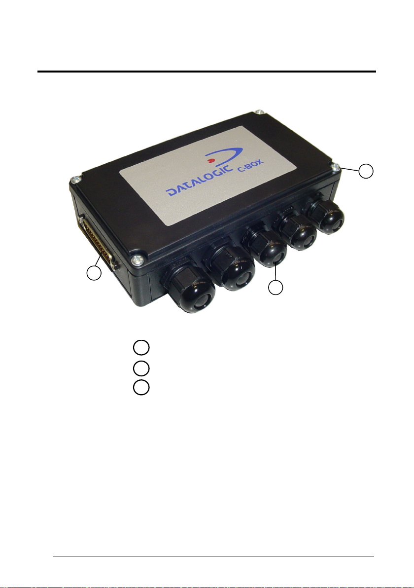
GENERAL VIEW
1
C-BOX 200
Figure A
25-pin scanner connector
1
3
2
vi
Compression connectors
2
Cover screws (4)
3
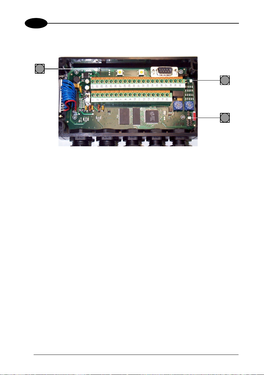
Page 7
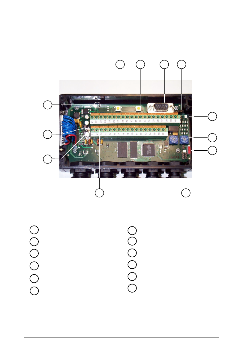
A
C-BOX 200
7
4
10
1
2
Figure B
Power switch (ON/OFF)
1
Spring clamp terminal blocks
2
Multidrop address switches
3
Power on LED
4
Warning LED
5
Tx LED
6
8
GET button
7
SEND button
8
uxiliary port connector
9
Chassis grounding selector
10
Termination resistance switch
11
OM4000 jumpers
12
9
12
6
5
3
11
vii
Page 8

GUIDE TO INSTALLATION
The following can be used as a checklist to verify all of the steps necessary for
complete installation of the C-BOX 200.
1) Read all information in the section "Safety Precautions" at the beginning of this
manual.
2) Correctly position and mount the C-BOX 200 within the reach of the barcode
scanner cable, according to the information in paragraph 2.3.
3) Make all electrical connections according to your application. See par. 2.4.
4) Set all the proper configuration jumpers and switches according to your
application. See all sub-paragraphs under 2.4.
5) Connect the scanner to the C-BOX 200.
6) Switch-on the system.
7) Wait until the Warning Led (WL, red) is switched off.
8) Through the internal 9-pin male connector, (it carries the Scanner Aux. Serial Port
signals), configure the scanner according to your specific application using the
WinHost™ software configuration tool.
9) Perform the 'Get Scanner Configuration' procedure using the internal keys (see
paragraph 2.7.1).
10) Wait until the Warning Led (WL, red) is switched Off.
Now the C-BOX 200 contains the scanner configuration.
The installation is complete.
viii
Page 9

INTRODUCTION
1
1 INTRODUCTION
1.1 PRODUCT DESCRIPTION
The C-BOX 200 is a connection box which can be used as an accessory to several
Datalogic family scanners.
Its main feature is to make the substitution of a Datalogic scanner in an installation
plain and easy.
To achieve this goal the C-BOX 200 provides the GET command to pass the
connected scanner’s configuration to the C-BOX 200 non volatile memory. The
SEND command allows a previously saved configuration to be transferred from the
C-BOX 200 to the scanner.
It also converts the scanner RS232 signals into RS485 optocoupled multidrop
signals.
The C-BOX 200 allows you to perform the following functions:
• Facilitate the connection of the scanner signals using a spring clamp connector.
• Perform a conversion from RS232 to RS485 multidrop system to connect a
RS232 scanner to a multidrop network.
• Get the scanner configuration and store it in memory.
• Send the configuration stored in memory to the scanner.
The C-BOX 200 mechanical dimensions are 161 x 114.5 x 40 mm (6.34 x 4.51 x 1.57
in.). The C-BOX 200 weighs about 340 g. (12 oz).
Electrical connection is provided through spring clamp terminal blocks inside the CBOX 200.
The scanner is connected to the C-BOX 200 through a 25-pin connector placed on
the left side of the housing.
A 9-pin connector placed inside the C-BOX 200 facilitates connection between an
external PC and the auxiliary serial interface of the scanner.
1
Page 10

2
C-BOX 200
2 INSTALLATION
2.1 PACKAGE CONTENTS
Verify that the C-BOX 200 and all the parts supplied with the equipment are present
and intact when opening the packaging; the list of parts includes:
1) C-BOX 200
2) Installation manual
3) 2 mounting screws
2
2
1
Figure 1 - C-BOX 200 Package Contents
Page 11

INSTALLATION
2
2.2 OPENING THE DEVICE
To install the C-BOX 200 or during normal maintenance, it is necessary to open it by
unscrewing the four cover screws:
The C-BOX 200 must be disconnected from the power supply
during this operation.
CAUTION
Figure 2 - Opening the C-BOX 200
It is possible to perform the following operations:
• Proceed with the cable connections (see paragraph 2.4.1).
• Set the multiplexer address selection on the rotary switches.
• Mount the C-BOX 200 to a wall or panel.
3
Page 12

2
C-BOX 200
2.3 MECHANICAL INSTALLATION
The diagram below gives the overall dimensions of the C-BOX 200 and may be used
for its installation.
12
66
[0.47]
[2.60]
Ø3.5
[Ø0.14]
5
[0.20]
150
[5.91]
161
[6.34]
5
[0.20]
40
90
[1.57]
[3.54]
12
[0.47]
89.8
[3.54]
114.5
[4.51]
mm
inch
Figure 3 - Overall Dimensions
4
Page 13

INSTALLATION
2
C-BOX 200 can be installed to operate in different positions. The two screw holes
inside the housing of the C-BOX 200 are for mechanical fixture (Figure 4).
To mount the C-BOX 200:
1) Open the C-BOX 200 by unscrewing the 4 cover screws. If necessary, using the
two mounting holes inside the device as a pattern, mark the panel with an
appropriate object and then drill two holes in the panel.
2) Align the C-BOX 200 and insert two screws and screw them into the panel until
tight (see Figure 4).
Figure 4 - Mounting C-BOX 200
5
Page 14

2
C-BOX 200
2.4 ELECTRICAL CONNECTIONS AND HARDWARE SETUP
The following figure shows the typical layout.
C-BOX 200
RS232
1
Scanner
2
PWR supply
3
RS485HD to Multiplexer
Scanner Main serial interface
1
Scanner Auxiliary serial interface (Local Echo)
2
External Trigger (for On-Line mode)
3
Laptop
Figure 5 – System Layout
A laptop PC can be connected to the C-BOX 200 (and consequently to the scanner
auxiliary interface) through the internal 9-pin connector. This allows monitoring of the
data transmitted by the scanner or scanner configuration through the WinHost utility
(see the scanner Reference Manual for more details). The scanner auxiliary interface
signals are also available on the internal spring clamp connectors.
The scanner configuration and data monitoring are possible once the warning LED is
turned OFF.
After making system cabling and switch settings, connect the scanner to the 25-pin
connector on the left side of the C-BOX 200 housing.
Switch ON the C-BOX 200 power switch (see Figure 8).
By default, after power on, an automatic connection procedure takes place between
the C-BOX 200 and the scanner. During this phase, requiring a few seconds, the
warning LED is turned ON. Once the procedure had been completed successfully,
the warning LED is turned OFF.
After system functioning has been verified, close the C-BOX 200 using the 4 cover
screws making sure the rubber seal is fitted correctly between the parts of the
housing.
6
Page 15

INSTALLATION
R
R
R
R
2
The following figure shows a multidrop layout with C-BOX 200 devices connected to
a Multiplexer:
(*)
SCANNE
SCANNE
SCANNE
EARTH GROUND
EARTH GROUND
EARTH GROUND
MULTIPLEXE
C-BOX 200
# N
(up to 31)
C-BOX 200
# 1
C-BOX 200
# 0
Three wires + shield
RTX485-
12
11
RTX485+
RS485 REF
10
CABLE SHIELD
9
13
CABLE SHIELD
14
RS485 REF
15
RTX485+
16
RTX485-
RTX485-
12
RTX485+
11
10
RS485 REF
9
CABLE SHIELD
13 CABLE SHIELD
14
RS485 REF
15
RTX485+
16
RTX485-
RTX485-
12
RTX485+
11
RS485 REF
10
CABLE SHIELD
9
CABLE SHIELD
RS485 REF
RTX485+
RTX485-
max 1200 m
EARTH GROUND
120 Ohm
(*) If necessary enable the termination resistor only in the last device.
Figure 6 - Multiplexer connection
7
Page 16

2
C-BOX 200
2.4.1 System Wiring
The connection and wiring procedure for C-BOX 200 is described as follows:
1) Open the C-BOX 200 as described in paragraph 2.2.
2) Verify that the C-BOX 200 power switch is off (see Figure 8).
3) Unscrew the compression connectors and pass all the system cables
through them into the C-BOX 200 housing.
4) To connect the power and input/output signals:
• Prepare the individual wires of the system cables by stripping the
insulation back approximately 1 cm.
• Using a device such as a screwdriver, push down on the lever directly
next to the clamp (see Figure 7).
• Insert the wire into the clamp and release the lever.
The wire will now be held in the spring clamp.
Figure 7 - System Cable Connections
The wiring used can be solid or stranded but must meet the following specifications.
All positions: 24 - 16 AWG 0.2 - 1.5 mm²
8
Page 17
INSTALLATION
2
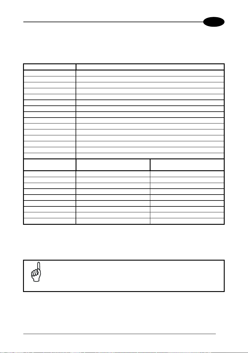
The C-BOX 200 spring clamp connector pinouts are indicated in the following table.
Refer to the scanner Installation Manual for details.
Pin Name
1, 3, 5 VS
2, 4, 6 GND
7, 8 EARTH GROUND
*9, 13 RS485 CABLE SHIELD
*10, 14 RS485 REF
*11, 15 RTX485+
*12, 16 RTX48520, 33, 34, 40 Reserved
21 OUT1+
23 OUT2+
27 EXT TRIG+
28 EXT TRIG35 TXA
37 RXA
39 SGND
DS2100A
22 OUT REF OUT124 OUT REF OUT225, 26 NC Reserved
29 NC IN1+
30 NC IN131 NC IN2+
32 NC IN236 RTSA GND
38 CTSA SGND AUX
• The signals on pins 9, 10, 11 and 12 are repeated on pins 13, 14, 15 and 16 to facilitate network
connections (i.e. Multiplexer connections using the RS485 half-duplex Interface). In this way the
network bus can enter and exit the C-Box 200 from different spring clamps but be physically connected
together.
DS2400A
DS4600A
Pin 7 or 8 should be connected to the earth ground.
Pin 17, 18 and 19 are not present in the C-BOX 200 model.
NOTE
9
Page 18

2
C-BOX 200
2.4.2 Power Supply
Power is supplied to the C-BOX 200 through the pins provided on the spring clamp
connector.
The power switch (see Figure 8) switches the power supply ON or OFF for both the
C-BOX 200 and the connected scanner.
Figure 8 - Power Switch ON/OFF Positions
C-BOX
VS
1
GND
2
Figure 9 - Power Supply Connections
The power supply must be between 10 and 30 Vdc only.
Pin 1 is also electrically connected to pins 3 and 5, just as pin 2 is
electrically connected to pins 4 and 6. This is useful for external
NOTE
trigger/inputs connections.
USER INTERFACE
V+ (10 - 30 Vdc)
GND
ON
OFF
10
Page 19

INSTALLATION
2
2.4.3 Scanner Chassis Grounding Jumper Settings
The scanner chassis grounding method can be selected by positioning a jumper (see
Figure 10). In this way the scanner chassis can be connected to earth ground (only if
pins 7 or 8 are connected to a good earth ground) or to the power supply ground
signal. The scanner chassis can also be left floating but, in this case, the jumper
must be removed.
to EARTH
GROUND
(default)
Figure 10 – Chassis Grounding
to GND floating
2.4.4 Multidrop Address Selection
For RS485 half-duplex interface connections, the scanner multidrop address should
be set using the rotary switches placed inside the C-BOX 200.
The valid address range is from 00 to 31. This value is read only at power-on; any
change at run-time has no effect.
If an invalid value is detected (32-99) the C-BOX cannot communicate with the
Multiplexer and the green LED remains off. Furthermore, the SEND command
configures the scanner using the previously configured valid scanner address.
TENS
Figure 11 - Rotary switches
UNITS
11
Page 20
2
C-BOX 200
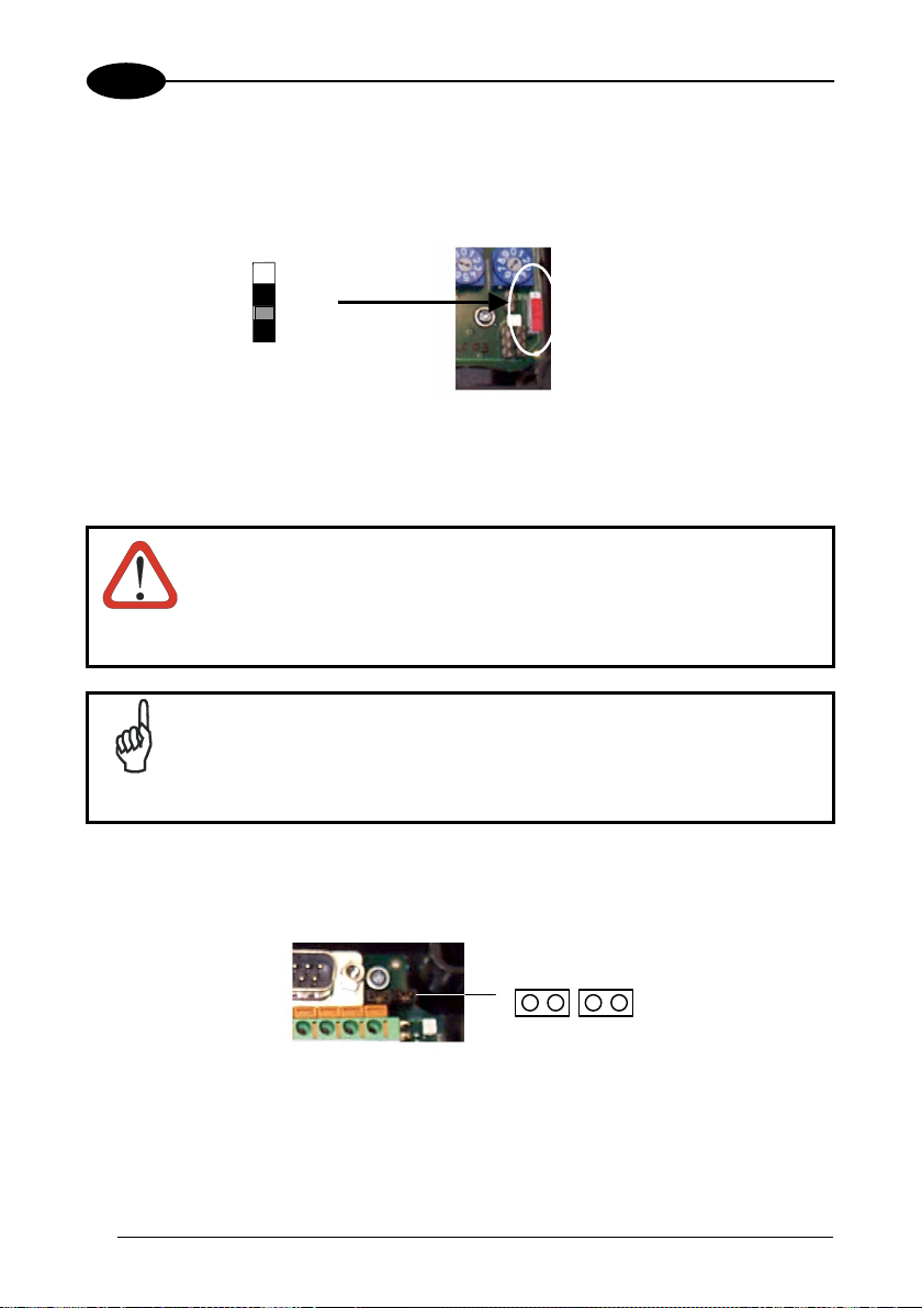
2.4.5 RS485 Bus Termination
ON
OFF
Figure 12 - Termination Resistance Switch
This switch enables or disables the insertion of the bus termination resistor for RS485
Half Duplex Multidrop applications.
In Multiplexer applications the termination resistor must be enabled
ONLY on the last device of the chain, the farthest away from the
Multiplexer (assuming the Multiplexer is the first device of the
chain). On all the other devices this resistor MUST NOT be enabled
CAUTION
(OFF position).
For all RS485 connections, in case of electrically noisy environments:
C-BOX 200 should be connected to a good earth ground (pin 7 or 8),
RS485 CABLE SHIELD should be connected to pin 7 or 8, the scanner
NOTE
chassis should be connected to EARTH GROUND through the jumper,
see Figure 10.
2.4.6 OM4000 Jumper Settings
J1 J2
Figure 13 - OM4000 Jumpers
The jumpers allow connection to the EXT TRIG signals on separate spring clamp
terminals for applications which use the OM4000 Oscillating Mirror in Trigger Mode.
12
Page 21
INSTALLATION
2
They are used together and they have the following significance:
when a jumper is in the J1 position (see Figure above) pin 40 is connected to pin 27
(EXT TRIG+); a jumper in J2 position connects pin 20 to pin 28 (EXT TRIG-).
If the jumpers are removed pin 20 and pin 40 are disconnected.
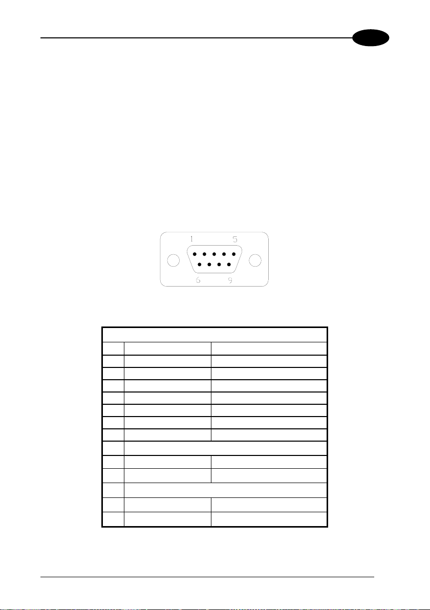
2.5 9-PIN INTERNAL CONNECTOR
The scanner auxiliary serial interface available on the internal 9-pin connector can be
used either for configuration through WinHost or for data monitoring.
The details of the connector pins are indicated in the following table:
Figure 14 - 9-pin male connector
9-pin connector pinout
Pin Name Function
1 N.C.
2 RXA Auxiliary RS232
3 TXA Auxiliary RS232
4 N.C.
5 SGND Signal Ground
6 N.C.
9 N.C.
DS2100A - DS2400A
7 CTSA Auxiliary Handshake RS232
8 RTSA Auxiliary Handshake RS232
DS4600A
7 SGND AUX Auxiliary Signal Ground
8 GND Ground
13
Page 22

2
C-BOX 200
2.6 SCANNER REQUIREMENTS
1) The C-BOX 200 can be connected to the following scanners through the 25-
pin connector illustrated in Figure A.
DS2100A
DS2400A DS4600A
For all scanners, the RS232 interface must be selected by the user.
2) At least one Terminator Character should be enabled in the connected
scanner (see the Terminator parameters in the Data Format section of the Help
On Line).
3) It is necessary to set the scanner main interface communication speed
(Baud Rate), so that it is the same as the Multidrop bus speed. In fact, during
the connection procedure, the C-BOX 200 gets its main interface speed from
the scanner to initialize its RS485 Multidrop optocoupled serial interface. If both
the baud rate and the device address are correct the communication takes
place which causes the green LED to blink slightly.
The device address must be pre-set through the two rotary switches (see Figure 11).
2.7 OPERATING MODES
Once the connection procedure is completed (the warning LED is OFF), the C-BOX
200 is ready to receive code strings from the scanner's RS232 main interface. Then,
it converts them to the RS485 multidrop network by using MUX32 protocol.
Through the C-BOX 200 internal buttons, it is possible to communicate with the
scanner to perform one of the following functions:
• Get scanner configuration
• Send a configuration to the scanner
At the end of each function the scanner returns to the previous operating mode.
14
Page 23
INSTALLATION
2
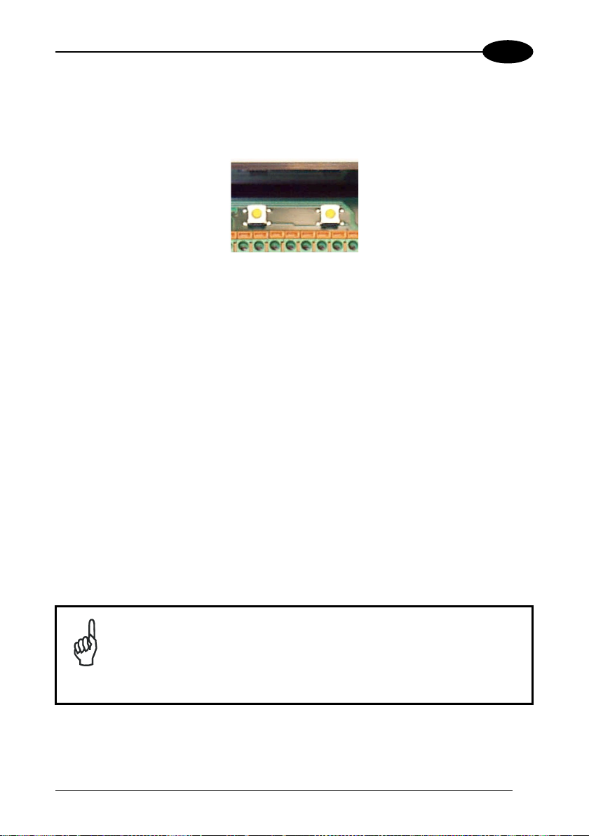
2.7.1 GET/SEND Buttons
The C-BOX 200 has two internal function buttons (GET, SEND).
C-BOX 200
GET SEND
Figure 15 – Internal Function Buttons
The procedure to enable the GET/SEND function is the following:
1. Press both the GET and SEND buttons at the same time for at least one second;
the warning LED will turn ON.
2. Release the buttons.
3. Press the left button corresponding to the GET function or the right button
corresponding to the SEND function.
GET – (left button): the C-BOX 200 reads the current scanner configuration
and permanently copies it in its own memory support (EEPROM). The
C-BOX 200 preserves this configuration also when switched off.
SEND - (right button): the C-BOX 200 sends the configuration previously stored
in its own permanent memory support to the scanner’s EEPROM.
Once the buttons are released in step 1, a ten-second timeout starts.
If no button is pressed within this time (no function is selected), the
procedure will be cancelled.
The C-Box 200 warning LED will turn OFF at the end of each
NOTE
procedure.
15
Page 24
2
C-BOX 200
2.7.2 LED Indicators
Power on
Warning
Tx
The internal LEDs of the C-BOX 200 (see Figure above) indicate the following:
POWER ON (red) indicates the C-BOX 200 is connected to the power
Figure 16 - LED Indicators
supply and the power switch is ON.
WARNING (red) indicates a warning or error condition: it is ON when
a connection procedure is in progress (the system is busy)
or during a GET/SEND procedure. It blinks when an error
condition occurs. Normally this LED should be OFF.
TX (green) indicates the RS485 Multidrop activity. When
communication takes place, this LED will blink slightly.
16
Page 25

INSTALLATION
2.8 SCANNER REPLACEMENT
If you have to replace the scanner with another one:
1. Switch-off the system.
2. Connect the new scanner.
3. Switch-on the system.
4. Wait until the Warning Led (WL, red) is switched Off.
5. Perform the Send prcedure (see par. 2.7.1).
Now the new scanner has been updated with the correct configuration!
2
17
Page 26

3
C-BOX 200
3 TECHNICAL FEATURES
ELECTRICAL FEATURES
Power
Supply voltage 10 to 30 Vdc
Power consumption max. 1.4 W + scanner
USER INTERFACE
LED indicators Power ON, Warning,
Tx (RS485 Multipdrop activity)
PHYSICAL FEATURES
Mechanical dimensions 161 x 114.5 x 40 mm (6.34 x 4.51 x 1.57 in)
Weight about 340 g. (12 oz.)
SOFTWARE FEATURES
Parameter storage Non-volatile internal memory
ENVIRONMENTAL FEATURES
Operating temperature
Storage temperature
Humidity max. 90% non condensing
Vibration resistance
EN 60068-2-6
Shock resistance
EN 60068-2-27
Protection class
-10 to 50
-20 to 70
14 mm @ 2 to 10 Hz;
1.5 mm @ 13 to 55 Hz;
2 hours on each axis
3 shocks on each axis
(when correctly connected to the scanner)
°C (14 to 122 °F)
°C (-4 to 158 °F)
2g @ 70-200 Hz
30g; 11 ms;
IP64
18
NOTE
The features given are typical at a 25 °C ambient temperature (if not
otherwise indicated).
Page 27

DECLARATION OF CONFORMITY
07
Datalogic Automation S.r.l.,
Via S. Vitalino 13
40012 - Lippo di Calderara
dichiara che
declares that the
déclare que le
bescheinigt, daß das Gerät
declare que el
C-BOX-XXX Connection Box; e tutti i suoi modelli
and all its models
et tous ses modèles
und seine Modelle
y todos sus modelos
sono conformi alle Direttive del Consiglio Europeo sottoelencate:
are in conformity with the requirements of the European Council Directives listed below:
sont conformes aux spécifications des Directives de l'Union Européenne ci-dessous:
der nachstehend angeführten Direktiven des Europäischen Rats:
cumple con los requisitos de las Directivas del Consejo Europeo, según la lista siguiente:
89/336/EEC EMC Directive e 92/31/EEC, 93/68/EEC emendamenti successivi
and further amendments
et ses successifs amendements
und späteren Abänderungen
y succesivas enmiendas
Basate sulle legislazioni degli Stati membri in relazione alla compatibilità elettromagnetica ed alla sicurezza dei
prodotti.
On the approximation of the laws of Member States relating to electromagnetic compatibility and product safety.
Basée sur la législation des Etats membres relative à la compatibilité électromagnétique et à la sécurité des produits.
Über die Annäherung der Gesetze der Mitgliedsstaaten in bezug auf elektromagnetische Verträglichkeit und
Produktsicherheit entsprechen.
Basado en la aproximación de las leyes de los Países Miembros respecto a la compatibilidad electromagnética y las
Medidas de seguridad relativas al producto.
Questa dichiarazione è basata sulla conformità dei prodotti alle norme seguenti:
This declaration is based upon compliance of the products to the following standards:
Cette déclaration repose sur la conformité des produits aux normes suivantes:
Diese Erklärung basiert darauf, daß das Produkt den folgenden Normen entspricht:
Esta declaración se basa en el cumplimiento de los productos con las siguientes normas:
EN 55022 (C
A
MENDMENT A1 (CLASS A ITE), October 2000
EN 61000-6-2, October 2001:
Lippo di Calderara, April 2nd, 2007 Lorenzo Girotti
LASS A ITE), August 1994:
Bologna - Italy
L
IMITS AND METHODS OF MEASUREMENTS OF RADIO DISTURBANCE
CHARACTERISTICS OF INFORMATION TECHNOLOGY EQUIPMENT
LECTROMAGNETIC COMPATIBILITY (EMC).
E
P
ART 6-2: GENERIC STANDARDS – IMMUNITY FOR INDUSTRIAL
ENVIRONMENTS
Product & Process Quality Manager
Page 28

www.automation.datalogic.com
 Loading...