

Page 1
Arex™ 400
User’s Manual
Laser Marker
Page 2

Datalogic S.r.l.
Via S. Vitalino, 13
40012 Calderara di Reno — Italy
Tel. +39 051 3147011
Fax +39 051 3147205
Arex™ 400 User’s Manual
Original Instructions
Ed.: 06/2019
This manual refers to Lighter™ Suite version 7.1.0 and later.
© 2018-2019 Datalogic S.p.A. and/or its affiliates
ALL RIGHTS RESERVED. Without limiting the rights under copyright, no part of this docu-
mentation may be reproduced, stored in or introduced into a retrieval system, or transmitted
in any form or by any means, or for any purpose, without the express written permission of
Datalogic S.p.A. and/or its affiliates.
Datalogic and the Datalogic logo are registered trademarks of Datalogic S.p.A. in many countries, including the U.S.A. and the E.U.
Arex™ 400, Arex™, Lighter™ Suite, Marvis™ and Matrix™ are trademarks of Datalogic
S.p.A.and/or its affiliates. All other trademarks and bands are property of their respective
owners.
Datalogic shall not be liable for technical or editorial errors or omissions contained herein, nor
for incidental or consequential damages resulting from the use of this material.
Page 3

Table of Contents
PREFACE .............................................................................................................................................................................. VII
Conventions ................................................................................................................................................................................... viii
General ........................................................................................................................................................................................... viii
Model Description ............................................................................................................................................................................ix
PRO Version ..............................................................................................................................................................................ix
BASIC Version ...........................................................................................................................................................................ix
CE Compliance ...................................................................................................................................................................................x
FCC Compliance .................................................................................................................................................................................x
EAC Compliance .................................................................................................................................................................................x
UL Compliance ..................................................................................................................................................................................xi
Laser Standards ..............................................................................................................................................................................xii
Overview ..........................................................................................................................................................................................xiii
Laser Source ...........................................................................................................................................................................xiii
Galvanometric scan head ......................................................................................................................................................xiii
Operation of a laser marker with galvanometric scanning ...............................................................................................xiii
Marking Software ...................................................................................................................................................................xiii
Important Warnings ..............................................................................................................................................................xiv
INSTALLATION....................................................................................................................................................................... 1
Unpacking ......................................................................................................................................................................................... 2
Contents of the packaging .............................................................................................................................................................. 4
On moisture condensation ............................................................................................................................................................. 5
Note on moisture condensation ............................................................................................................................................. 5
If moisture condensation occurs ............................................................................................................................................ 5
How to avoid moisture condensation .................................................................................................................................... 5
Fixing and positioning ..................................................................................................................................................................... 6
Control Rack installation ................................................................................................................................................................. 7
Horizontal installation ............................................................................................................................................................. 7
Vertical installation .................................................................................................................................................................. 9
Control rack mounting screws length .................................................................................................................................. 10
Scan Head installation .................................................................................................................................................................. 11
Scan head mounting screws length ..................................................................................................................................... 14
Installation environment .............................................................................................................................................................. 15
Control rack ............................................................................................................................................................................. 15
Scan Head ............................................................................................................................................................................... 16
Fume / Dust extractor ................................................................................................................................................................... 17
TECHNICAL SPECIFICATIONS.............................................................................................................................................. 18
Technical Characteristics .............................................................................................................................................................. 19
Product Description ....................................................................................................................................................................... 20
Control rack ............................................................................................................................................................................. 20
Scan head ................................................................................................................................................................................ 21
Marking Area Specification ........................................................................................................................................................... 22
F-Theta Scan Lens for Arex™ 110-XXX, 120-XXX and A20-X6X ........................................................................................ 22
F-Theta Scan Lens for Arex™ 130-X6X and 150-X6X ......................................................................................................... 23
Green Spot ....................................................................................................................................................................................... 24
Connectors Specifications ............................................................................................................................................................. 25
Safety Circuit ........................................................................................................................................................................... 25
Control rack back panel connector ............................................................................................................................... 25
Muting Device ................................................................................................................................................................. 27
Command Box (Laser Control) .............................................................................................................................................. 28
User Manual iii
Page 4

Contents
Control rack back panel connector ................................................................................................................................28
Muting Device .................................................................................................................................................................29
Axes (I/O Control) ....................................................................................................................................................................30
Control rack back panel connector ................................................................................................................................30
Encoder ....................................................................................................................................................................................31
Control rack back panel connector ................................................................................................................................31
Photocell ..................................................................................................................................................................................31
Control rack back panel connector ................................................................................................................................31
Device Port 1 ...........................................................................................................................................................................32
Control rack back panel connector ................................................................................................................................32
Device Port 2 ...........................................................................................................................................................................32
Control rack back panel connector ................................................................................................................................32
RS232 (COM3) ..........................................................................................................................................................................33
Control rack back panel connector ................................................................................................................................33
Ext Focus .................................................................................................................................................................................33
Scan head connector ......................................................................................................................................................33
Input/Output specifications ..........................................................................................................................................................34
Digital Input .............................................................................................................................................................................34
Digital Output ..........................................................................................................................................................................34
Laser Marker States .......................................................................................................................................................................35
Normal Operation States .......................................................................................................................................................35
Error States .............................................................................................................................................................................35
Warning State .........................................................................................................................................................................35
Control the Laser Marker States ...........................................................................................................................................36
Key Selector mode ..........................................................................................................................................................36
Command Box mode ......................................................................................................................................................36
Timing Diagrams .............................................................................................................................................................................37
Turning On sequence ..............................................................................................................................................................37
Marking control signals behavior ..........................................................................................................................................37
SW_Ready output signal (Ready to Mark mode) .................................................................................................................38
Good\Bad output signal ........................................................................................................................................................38
System_Alarm output signal .................................................................................................................................................38
MARVIS™ I/O signals behavior ..............................................................................................................................................39
Safety functions behavior ......................................................................................................................................................39
Interlock behavior ...........................................................................................................................................................39
Laser_Stop behavior .......................................................................................................................................................39
Green Spot behavior ...............................................................................................................................................................40
System Ready to Mark mode ........................................................................................................................................40
Marking Confirmation mode .........................................................................................................................................40
MARVIS Verification mode .............................................................................................................................................40
Axes I/O signals behavior ......................................................................................................................................................41
Lighter™ Suite marking software ..................................................................................................................................................42
INSTALLATION AND SET UP............................................................................................................................................... 44
Connections .....................................................................................................................................................................................45
Connecting Command Box connector ..................................................................................................................................45
Connecting Safety Circuit connector .....................................................................................................................................46
Connecting Power Supply cable ............................................................................................................................................47
Connecting the Earth Ground ................................................................................................................................................47
Local Mode Control connections ...........................................................................................................................................48
Remote Mode Control connection ........................................................................................................................................49
F-Theta scan lens protection cap removal ..................................................................................................................................49
USE AND OPERATION......................................................................................................................................................... 50
First time boot .................................................................................................................................................................................51
Turning On sequence ......................................................................................................................................................................52
Sequence using Key Selector .................................................................................................................................................52
Sequence Using Command Box .............................................................................................................................................55
CUSTOMIZE THE LASER MARKER SOFTWARE ................................................................................................................ 56
Change O.S. language and keyboard layout ................................................................................................................................57
Change the LAN configuration and IP address ...........................................................................................................................60
Change the video setting ...............................................................................................................................................................63
iv
Arex™ 400
Page 5

Contents
Remote desktop connection ......................................................................................................................................................... 65
ACCESSORIES....................................................................................................................................................................... 66
Control Box ...................................................................................................................................................................................... 67
Remote Start Foot Switch ............................................................................................................................................................. 67
I/O interface ................................................................................................................................................................................... 68
DB25-to-Free Leads Cable ............................................................................................................................................................ 68
MARVIS™ Add-on ............................................................................................................................................................................ 69
MARVIS™ Mounting Bracket ................................................................................................................................................. 69
MARVIS™ LED Ring Light ID 50mm - White ........................................................................................................................ 69
Micrometric distance sensor kit ................................................................................................................................................... 70
M39 F-Theta protective cap .......................................................................................................................................................... 70
Starter Kit for Marking On the Fly (MOF) ..................................................................................................................................... 71
Rack Handles .................................................................................................................................................................................. 71
Fume Extractor ............................................................................................................................................................................... 71
TECHNICAL SUPPORT ......................................................................................................................................................... 72
Seals ................................................................................................................................................................................................ 73
Maintenance ................................................................................................................................................................................... 74
F-Theta scan lens cleaning procedure ................................................................................................................................. 74
Air filter cleaning procedure .................................................................................................................................................. 75
Troubleshooting ............................................................................................................................................................................. 76
Service Interface ..................................................................................................................................................................... 76
List of warning and error states ........................................................................................................................................... 77
List of problems related to laser marker states ................................................................................................................. 77
List of most common problems ........................................................................................................................................... 78
Remote Assistance ........................................................................................................................................................................ 79
Product Support and Customer Service ....................................................................................................................................... 79
LABELS ............................................................................................................................................................. 80
Labels .............................................................................................................................................................................................. 81
Positioning of external labels ....................................................................................................................................................... 82
Positioning of labels on the control rack: ............................................................................................................................ 82
Positioning of labels on the scan head: ............................................................................................................................... 82
Safety labels in local languages ................................................................................................................................................... 83
UNDERSTANDING SLO: SAFE LASER OFF..................................................................................................... 84
Machine Safety ............................................................................................................................................................................... 85
Risk Assessment ............................................................................................................................................................................ 86
Performance Level (PL) .................................................................................................................................................................. 87
Datalogic Laser Markers ............................................................................................................................................................... 87
SLO connection diagram ............................................................................................................................................................... 88
Safety Functions Of Arex™ 400 ..................................................................................................................................................... 89
Arex™ XXX-X5X ....................................................................................................................................................................... 89
Arex™ XXX-X6X ....................................................................................................................................................................... 89
Example 1 ................................................................................................................................................................................ 90
Example 2 ................................................................................................................................................................................ 91
Example 3 ................................................................................................................................................................................ 92
LASER SAFETY................................................................................................................................................. 93
Laser radiation ............................................................................................................................................................................... 95
Absorption of laser radiation ........................................................................................................................................................ 96
Classification and danger level .................................................................................................................................................... 97
Degree of risk with radiation viewing conditions ...................................................................................................................... 97
Direct viewing of the laser beam .......................................................................................................................................... 97
Viewing of a laser reflected beam ........................................................................................................................................ 98
Viewing of direct laser beam from a fiber output .............................................................................................................. 98
Viewing of scattered laser beam .......................................................................................................................................... 98
N.O.H.D. determination and O.D. of protection goggles ............................................................................................................ 99
Accidental vision of the reflected laser radiation ............................................................................................................. 100
Filter scale index of the protection goggles ...................................................................................................................... 100
Eyes and skin risks ......................................................................................................................................................................100
General safety regulations ..........................................................................................................................................................100
Other risks ....................................................................................................................................................................................101
User Manual v
Page 6

Contents
USING MARKING SOFTWARE....................................................................................................................... 102
How to create and edit graphics layout .................................................................................................................................... 103
How to test and mark layout ...................................................................................................................................................... 106
How to use Command Box signals to mark layout .................................................................................................................. 108
MOPA FIBER LASER ...................................................................................................................................... 110
Laser marker operations ............................................................................................................................................................. 111
Pulse Profile ......................................................................................................................................................................... 113
Lighter™ Pulse Profile Configuration ......................................................................................................................................... 115
Creating a document with multiple objects using a single pulse profile ...................................................................... 115
Creating a document with multiple objects using different pulse profiles ................................................................... 116
MARKING SOFTWARE UPGRADE................................................................................................................. 118
How to update the marking software ....................................................................................................................................... 119
RECOVER THE LASER MARKER.................................................................................................................... 124
Overview ....................................................................................................................................................................................... 125
How to recover the laser marker ............................................................................................................................................... 125
Recover the system: ............................................................................................................................................................ 125
Initialize the Hardware ........................................................................................................................................................ 128
Customize the marking software ...................................................................................................................................... 129
MECHANICAL DRAWINGS............................................................................................................................. 130
Control Rack ................................................................................................................................................................................. 131
Scan Head ..................................................................................................................................................................................... 132
vi
Arex™ 400
Page 7

CONVENTIONS starting on page viii
GENERAL starting on page viii
MODEL DESCRIPTION starting on page ix
CE COMPLIANCE starting on page x
FCC COMPLIANCE starting on page x
EAC COMPLIANCE starting on page x
UL COMPLIANCE starting on page xi
LASER STA ND AR DS starting on page xii
OVERVIEW starting on page xiii
Preface
User Manual vii
Page 8
Preface
Conventions
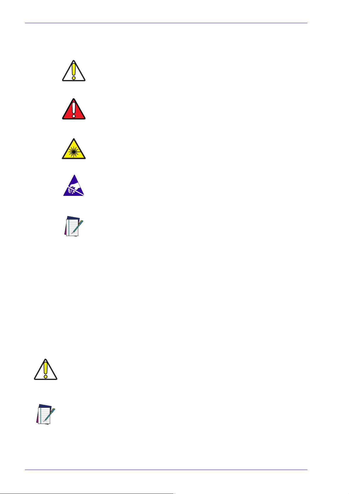
Warnings
High Voltage
Laser Caution
ESD
Notes
This symbol identifies a hazard or procedure that, if incorrectly performed, could cause personal injury or result in
equipment damage. It is also used to bring the user’s attention to details that are considered IMPORTANT.
This symbol alerts the user they are about
action involving, either a dangerous level of voltage, or to warn
against an action that could result in damage to devices or
electrical shock.
This symbol alerts the user they are about
action involving possible exposure to laser light radiation.
This symbol identifies a procedure that requires you take
measures
ESD wrist strap. Circuit boards are most at risk. Please follow
ESD procedures.
This symbol draws attention to details or procedures that may
be useful in improving,
mance of the hardware or software being discussed.
to prevent Electrostatic Discharge (ESD) e.g., use an
maintaining, or enhancing the perfor-
to perform an
to perform an
General
W
ARNING
NOTE
Information included in this manual is intended for a qualified installer able to
integrate the laser marker into a system, complying with all the protection features required by international rules and local legislations. Refer to the following
ctions for further information.
se
This manual refers to Arex™ 400 Fiber laser markers, that is a Class 4 Laser
oduct.
Pr
In addition to being professi
work with laser marker must be informed and made acquainted with the risks
inherent to invisible and visible laser radiation. The operator is required to carefully read the section of the manual concerni
sections related to matters falling under her/his responsibility.
Datalogic shall not be held responsible for any no
its manufacture.
BEFORE INSTALLING AND USING THE LASER, CAREFULLY READ THIS MANUAL.
onally trained in their role, personnel assigned to
ng safety instructions as well as the
n-conforming use of laser marker of
viii
Arex™ 400
Page 9
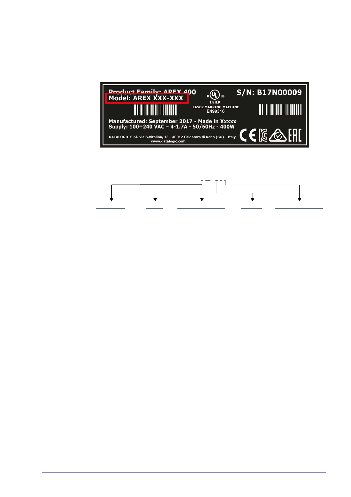
Model Description
Arex™ 400 laser markers are described by their model number which indicates
the characteristics listed in the diagram below. Not all combinations are available. For a complete list of combinations see the Models tab on the Product page
the website.
of
Model Description
AREX XXX-XXX
PRO Version
• Wider power range selection
• Wider F-Theta scan lens selection
• High performance level for safety features
• High PC performance (powered by Intel® Celeron®)
• 3x Ethernet ports 10/100/1000 Mbps
• High Precision Marking Field Center specifications
• Advanced software features
Laser Type Power F-Theta scan lens Version Operating System
1 = Pulsed Fiber 10 = 10W 3 = 160 S 5 = BASIC 4= Windows® 7
A = Fiber MOPA 20 = 20W 4 = 160L 6 = PRO
30 = 30W 6 = 254 S
50 = 50W 7 = 254 L
9 = 100 L
A = 330 L
B = 420 L
BASIC Version
• Models with power level 10W & 20W
• Basic performance level for safety features
• Basic PC performance (powered by Intel® Atom®)
• 1x Ethernet port 10/100/1000 Mbps
• Basic Precision Marking Field Center specifications
• Basic software features
User Manual ix
Page 10

Preface
CE Compliance
CE marking states the compliance of the product with essential requirements
listed in the applicable European directive. Since the directives and applicable
standards are subject to continuous updates, and since Datalogic promptly
adopts these updates, therefore the EU declaration of conformity is a living document. The EU declaration of conformity is available for competent authorities
d customers through Datalogic commercial reference contacts. Since April
an
20th, 2016 the main European directives applicable to Datalogic products
require inclusion of an adequate analysis and assessment of the risk(s). This
evaluation was carried out in relation to the applicable points of the standards
listed in the Declaration of Conformity. Datalogic products are mainly designed
for integration purposes into more complex systems. For this reason it is under
the responsibility of the customer to do a new risk assessment regarding the
final installation.
This is a Class A product. In a domestic environment this product may cause radio
interference in which case the user may be required to take adequate measures.
W
ARNING
FCC Compliance
Modifications or changes to this equipment without the expressed written
approval of Datalogic could void the permission to use the equipment.
This laser marker complies with PART 15 of the FCC Rules. Operation is subject
the following two conditions: (1) this laser marker may not cause harmful
to
interference, and (2) this laser marker must accept any interference received,
including interference which may cause undesired operation.
This laser marker has been tested and found to
A digital device, pursuant to part 15 of the FCC Rules. These limits are designed
to provide reasonable protection against harmful interference when the equipment is operated in a commercial environment. This laser marker generates,
and can radiate radio frequency energy and, if not installed and used in
uses,
accordance with the instruction manual, may cause harmful interference to radio
communications. Operation of this laser marker in a residential area is likely to
cause harmful interference in which case the user will be required to correct the
interference at his/her own expense.
EAC Compliance
Customs Union: this laser marker complies with CU Conformity certification; this
allows the Product to bear the Eurasian Mark of conformity.
comply with the limits for a Class
x
Arex™ 400
Page 11

UL Compliance
Reading this manual prevents the operator from carrying out operations that
could cause damage to himself or others.
UL Compliance
Follow-Up Service Procedure issued on 2019-03-26.
User Manual xi
Page 12

Preface
Laser Standards
This laser marker is classified as Class 4 Laser Product according to the following:
EU: EN60825-1
USA: 21 CFR 1040.10
China: GB7247-1
Datalogic, as manufacturer of laser products, provides a laser marker which is
NOT
intended for immediate use, but it must be connected, by others, to other
devices which have the final aim of creating a laser processing system.
The final system manufacturer MUST ensure
machine according to its standards including the risk-analysis, implementation
of safety measures, certification and testing of safety measures and the production of adequate information for use of the machine.
Datalogic is available for providing to the customers all the information in its
ession to help in complying with applicable standards.
poss
Use of controls or adjustments or performance of procedures other than those specified herein may result in hazardous radiation exposure.
CAUTION
the safety of the laser processing
xii
Arex™ 400
Page 13

Overview
The Fiber laser marker developed and manufactured by Datalogic employs the
most advanced technologies with regards to the opto-mechanical parts, the
electronic control of laser beam power, communication and the overall safety of
the entire marker.
The Arex™ 400 laser marker features a contro
rack size is standard 19" 2.5U. The scan head compact dimensions make it easy
to integrate.
All product connections are on the rear or front of the control rack.
Laser Source
On Arex™ 400 laser marker it is used a sealed fiber laser source. This source is
based on the new fiber solid state technology. It guaranties high stability, lower
sensitivity to optical misalignment and a longer product lifetime.
Galvanometric scan head
The scan head features two deflection mirrors that deflect the beam in X and Y
directions, depending on the graphics/pattern to be reproduced.
Overview
l rack and a scan head. The control
Operation of a laser marker with galvanometric scanning
During the marking the laser generates an invisible, high-energy infrared beam.
In order to obtain a more accurate focus, the laser beam is first enlarged using
an optical expansion system and then deflected by a scanning system consisting
of two mirrors mounted on galvanometric motors.
These mirrors deflect the beam in a controlled path along the
cessing of the product surface occurs by coordinating the movement of the two
irrors and the turning on/off of the laser beam.
m
The deflected laser beam is focused by an F-Th
the product.
Generally speaking, the marking is carried out within the focus plane of the F-
eta scan lens.
Th
eta scan lens on the surface of
Marking Software
The Ligther™ marking software is preinstalled on the product.
Consult Lighter™ software user's manual for a proper use of the same.
NOTE
X and Y axes; pro-
If necessary, consult “How to update the marking soft
preinstalled software.
NOTE
ware” on page 97, to upgrade the
User Manual xiii
Page 14
Preface
Important Warnings
Access to the internal parts of the laser marker is allowed only to authorized
personnel, duly qualified and trained with regards to risks of optical and electrical nature.
Datalogic declines any and all responsibility for work carried out on active parts
by
untrained or unauthorized personnel.
It is forbidden to change the intended use for which the product was designed and
developed.
W
ARNING
Datalogic declines any and all responsibility for improper use of its laser product.
W
ARNING
W
ARNING
W
ARNING
W
ARNING
The integration and use of this laser marker is custo
Never expose reflecting surface
The reflected laser beam may cause damage to laser marker.
Laser marking interacts with materials through,
process which may lead to the emission of fumes, dust and vapors.
Adequate fume/dust extractor and treatment must be provided by customer!
Marking PVC (or other plastic material) can cause the re
be harmful to the laser operator and to the laser marker itself. Always use adequate
fume extractor during PVC and plastic marking.
s to laser radiation!
mer responsibility.
for example, a thermal carbonization
lease of chlorine gas which can
xiv
W
ARNING
It is the responsibility of the customer to inst
dition!
all the laser marker in proper safety con-
Arex™ 400
Page 15

UNPACKING starting on page 2
CONTENTS OF THE PAC KA GING starting on page 4
ON MOISTURE CONDENSATION starting on page 5
FIXING AND POSITIONING starting on page 6
CONTROL RACK INSTALLATION starting on page 7
SCAN HEAD INSTALLATION starting on page 11
INSTALLATION ENVIRONMENT starting on page 15
FUME / DUST EXTRACTOR starting on page 17
Chapter 1
Installation
User Manual 1
Page 16
Installation
Unpacking
Control rack and scan head are joined by a connection cable 3 meters long, referred as
Head Cable. Control rack and scan head are NOT separable.
W
ARNING
W
ARNING
W
ARNING
W
ARNING
Be extremely careful to not damage the connection c
trol rack.
To avoid damaging or breaking the optical fibe
bending radius below the limits specified in the technical specification table (see
“Technical Characteristics” on page 19).
The Arex™ 400 laser marker is a delicate optical device, that can be damage by shock
and vibrations.
able between scan head and con-
r, never subject the Head Cable to a
2
Arex™ 400
Page 17
Before installing or operating the laser marker, you should:
- Inspect the shipping container for damage
- Inspect the laser marker for signs of damage
- Confirm that the shipping box contains all items on the shipping inventory list
including any accessories
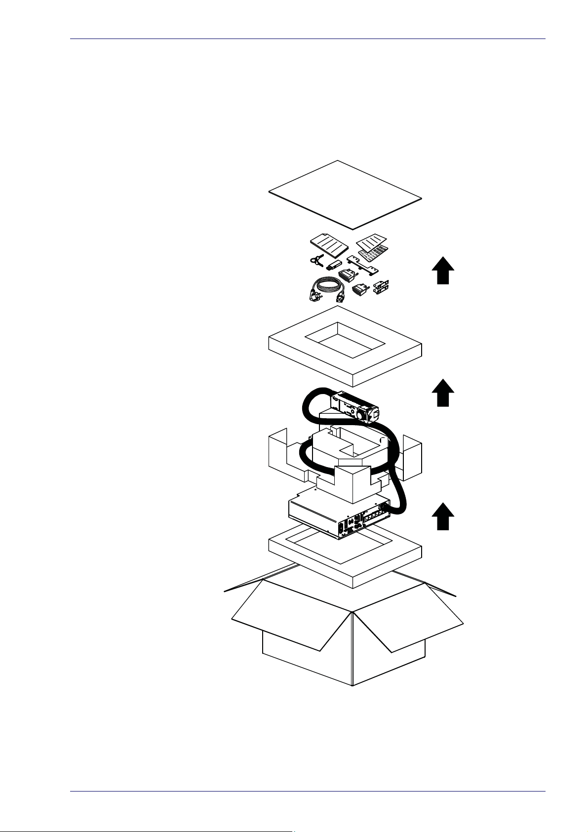
When unpacking the laser marker from the shipping box you should:
- Remove the accessories and documentations
- Carefully remove the laser marker from the packaging using both hands
Unpacking
Figure 1: Unpacking
Keep all packing materials until the laser has been inspected for completeness
and damage. If something is missing or defective, call Datalogic (see
Support and Customer Service” on page 79 for contact details).
“Product
User Manual 3
Page 18
Installation
3x
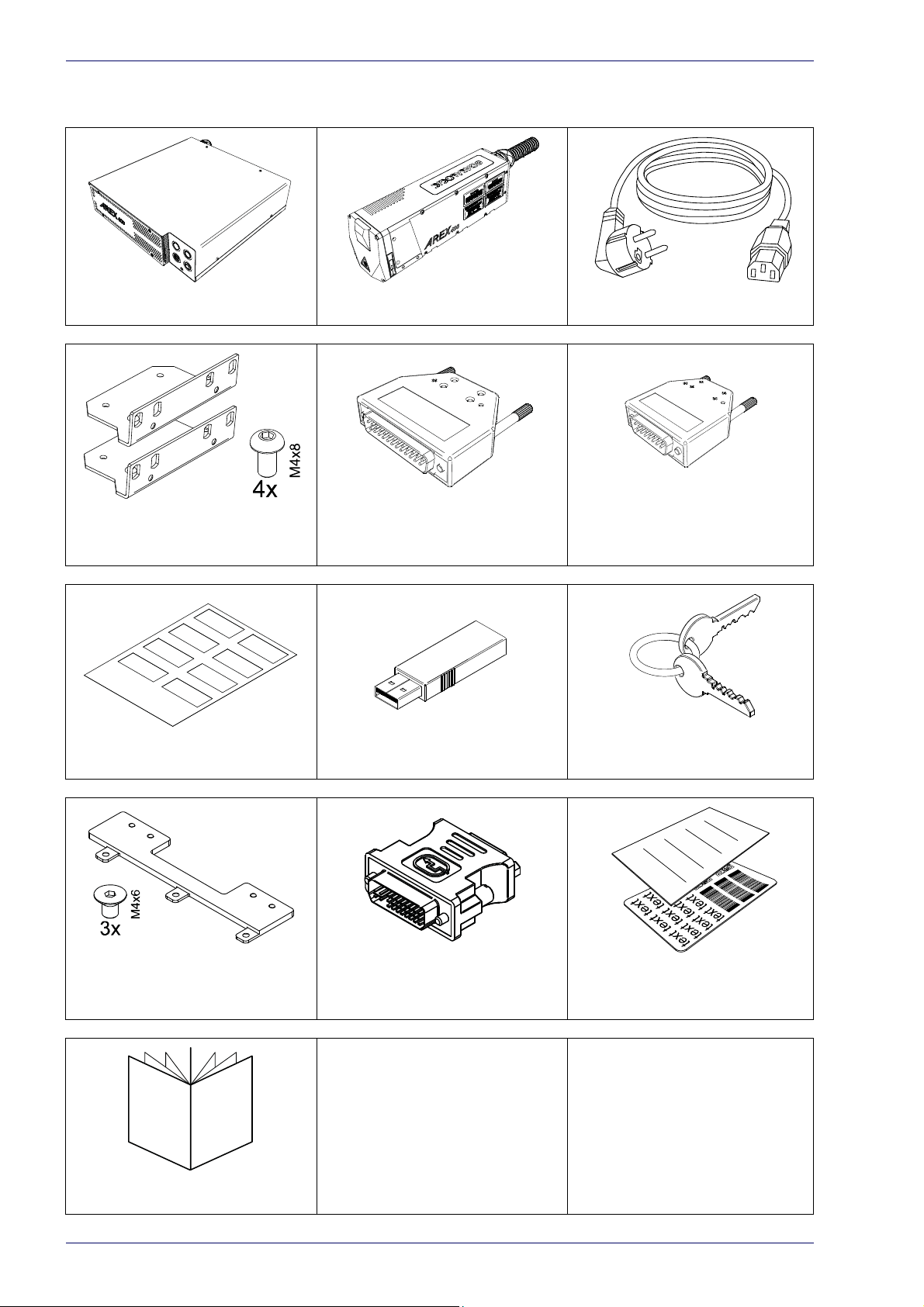
Contents of the packaging
Control Rack Scan Head Power Supply cables
Rack Fixing Brackets
(Only for XXX-X6X models)
Safety labels USB Recovery Disk Selector Keys
Command Box
MUTING DEVICE
Safety Circuit
MUTING DEVICE
Scan Head Fixing Bracket
Quick Reference Guide
4
VGA to DVI Adapter
(Only for XXX-X6X models)
Test report and sample test
plate
Arex™ 400
Page 19

On moisture condensation
If the laser marker is brought directly from a cold to a warm location, moisture
may condense inside or outside the laser product. This moisture condensation
may cause a malfunction of the laser marker.
Note on moisture condensation
Moisture may condense when you bring the laser marker from a cold place into a
warm place (or vice versa) and when you use the laser marker in a humid place.
If moisture condensation occurs
Turn off the laser marker and wait about 1 hour for the moisture to evaporate.
How to avoid moisture condensation
Before moving the laser marker from a cold place into a warm place, put it in a
plastic bag and seal it tightly. Remove the bag when the air temperature inside
the plastic bag has reached the ambient temperature (after about 1 hour).
On moisture condensation
User Manual 5
Page 20
Installation
Fixing and positioning
Fix the laser marker according to instructions shown in the figures.
W
ARNING
W
ARNING
W
ARNING
NOTE
NOTE
It is mandatory to secure the laser marker before you
securing or positioning may cause serious damage.
Do not secure the laser marker in a way other than the one described in the figure.
Introduction of optical or mechanical surfaces,
tional protective glass, between F-Theta scan lens output and marking surface may
case optical feedback into the laser marker.
Optical induced damage caused to laser marker by reflection from external surfaces is
not covered by warranty.
In order to prevent marking distortions, avoid vibrations and bumps during
ing process!
It is recommended to install the scan head on a positioning Z-axis
such as mechanical shutters or addi-
start marking, since improper
the mark-
system for accu-
rate mounting at focal distance!
6
Arex™ 400
Page 21
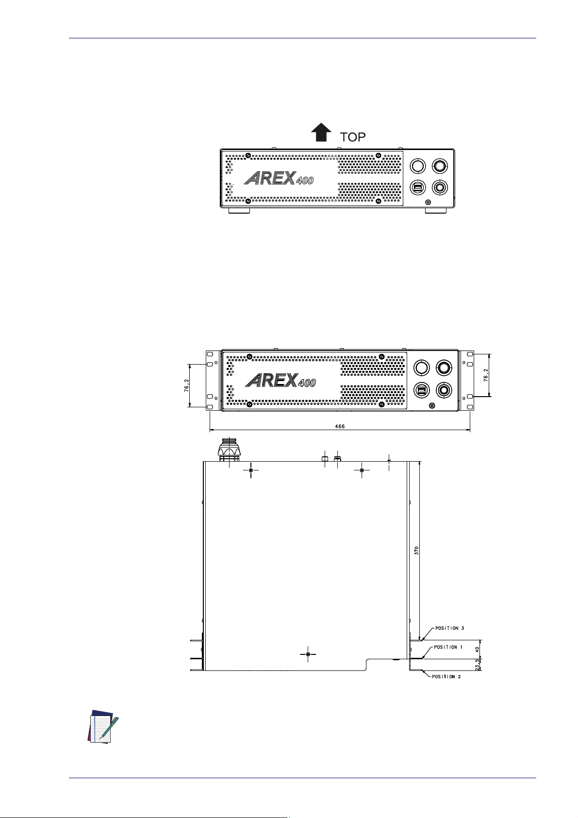
Control Rack installation
Horizontal installation
The control rack must be positioned in a safe manner, following the recommendations below:
Figure 2: Control rack horizontal positioning
The control rack can be installed on a standard 19" rack cabinet using the fixing
brackets supplied as a standard equipment with XXX-X6X models and as an
accessory for XXX-X5X models (see "Ra
The figure below shows the fixing points for installation in a rack cabinet. Rack
ha
ndles for an easier installation are available as an accessory (see "Ra
dles" on page 71).
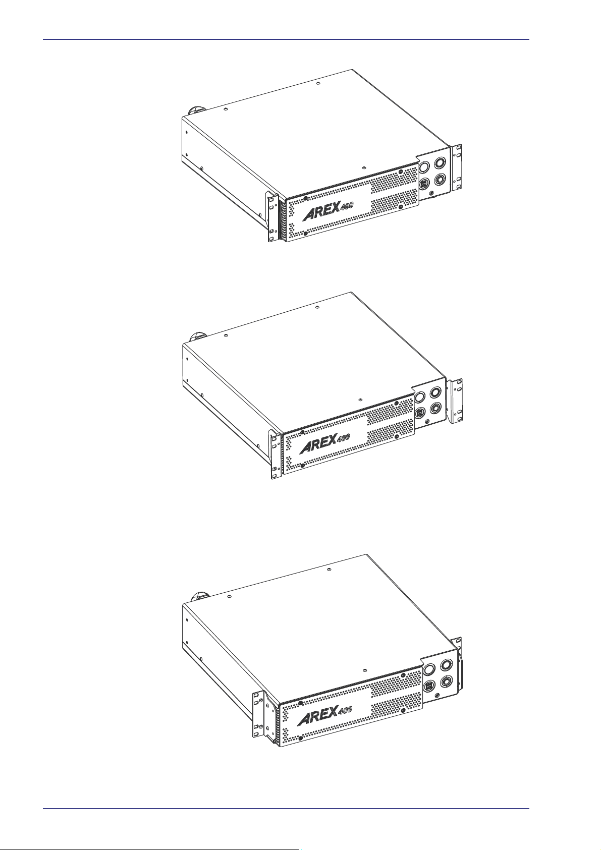
Using the fixing brackets is possible to install the control rack in three different
positions
inside the cabinet:
Control Rack installation
ck Handles" on page 71).
ck Han-
Figure 3: Control rack fixing bracket mounting configuration
All dimensions are in millimeters.
NOTE
User Manual 7
Page 22
Installation
Using this position the fixing brackets are aligned with the console.
Figure 4: Control rack fixing brackets mounting position 1
Using this position the fixing brackets are aligned with the frontal grid panel.
Figure 5: Control rack fixing brackets mounting position 2
Use this position if you want to use a pre-existing integration for AREX™ 3 and it
is required that the back panel of AREX™ 400 is in the same position as the back
panel of AREX™ 3 inside the cabinet.
Figure 6: Control rack fixing brackets mounting position 3
8
Arex™ 400
Page 23
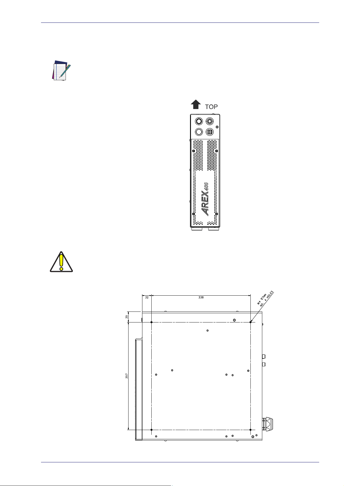
Vertical installation
The control rack must be positioned in a safe manner, following the recommendations below.
The feet must be removed from the bottom of the control rack and installed on the left
side of the control rack using the appropriate fixing points. Tightening torque = 0.5 Nm.
NOTE
Control Rack installation
W
ARNING
Figure 7: Control rack vertical positioning
The control rack MUST be fixed to a side wall using the appropriate fixing points placed
on the bottom of the
control rack.
Figure 8: Control rack fixing points for vertical installation
User Manual 9
Page 24

Installation
Control rack
7 mm
Mounting plate thickness
Washer thickness
M4 screw
Control rack mounting screws length
To determine the length of the mounting screws, consider the thickness of the
mounting plate and the thickness of the washer.
Figure 9: Length of mounting screws
Mounting holes depth is =7mm. Tightening torque = 2 Nm.
NOTE
10
Arex™ 400
Page 25
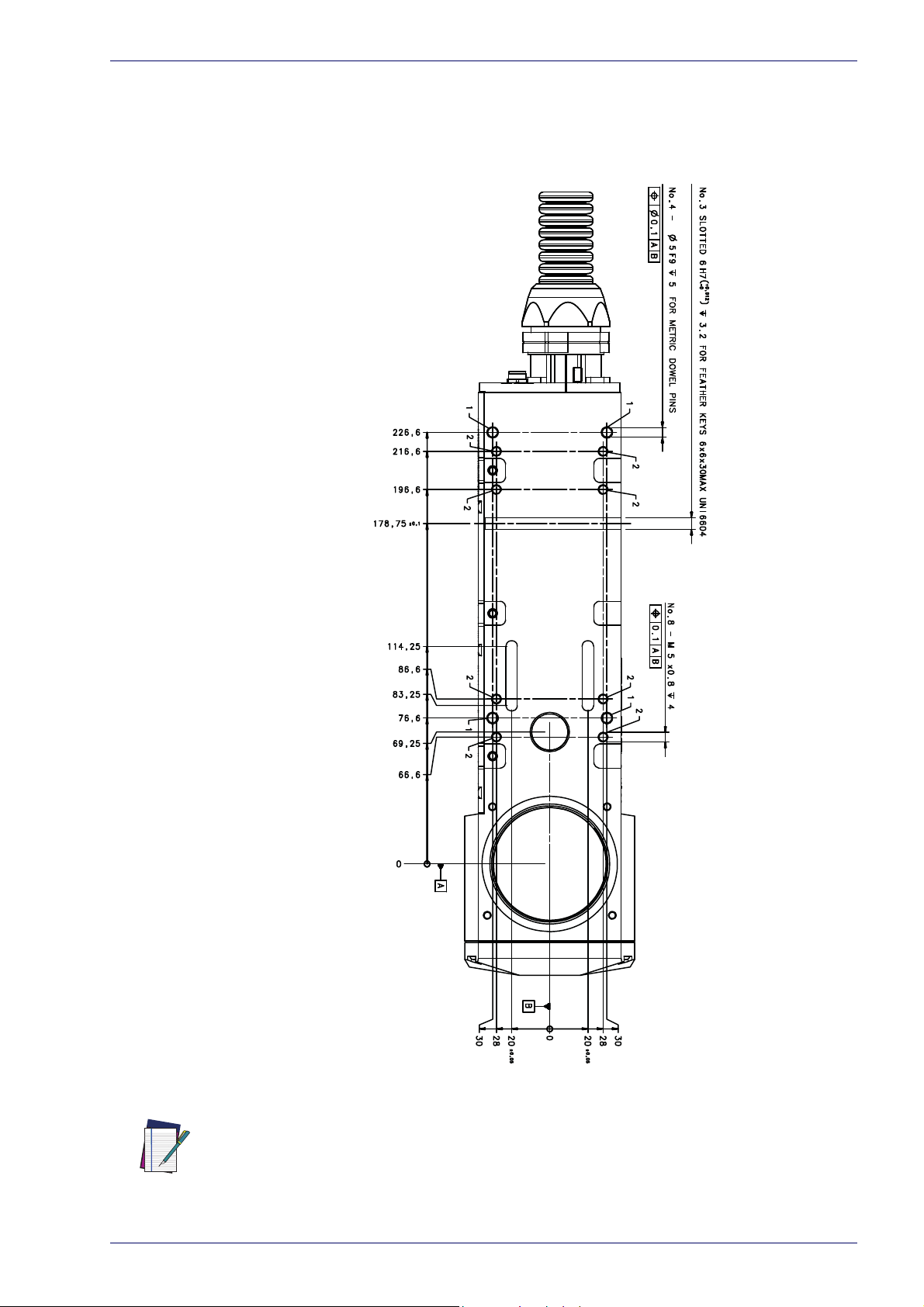
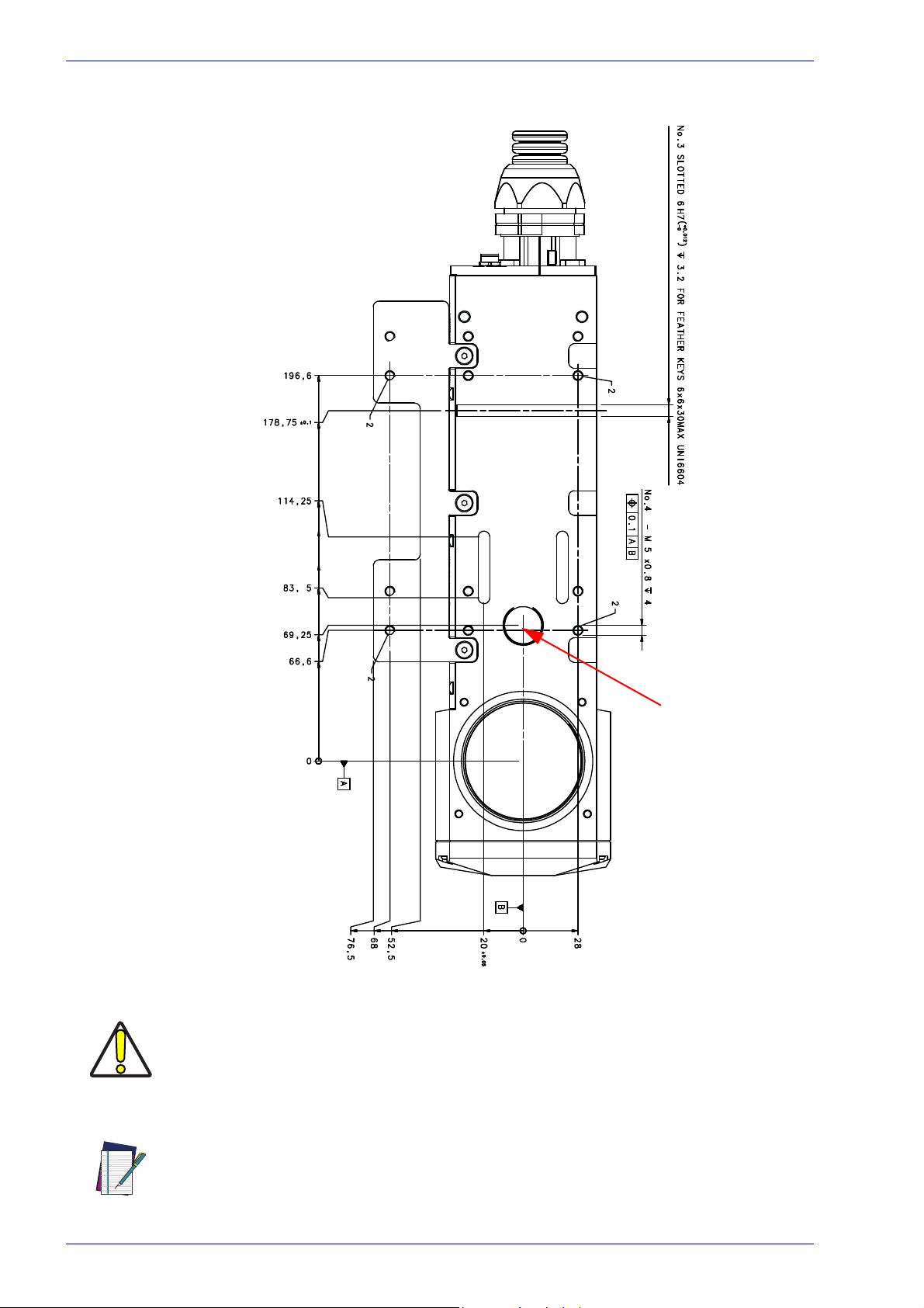
Scan Head installation
The scan head can be installed in any orientation and must be fixed to a suitable
base (not supplied by Datalogic) using the dedicated threaded holes and the high
precisions slotted seats:
Scan Head installation
Figure 10: Fixing points on scan head (bottom view)
All dimensions are in millimeters.
NOTE
User Manual 11
Page 26
Installation
Focusing Beam output
A fixing bracket for scan head is provided to offer dedicated threaded holes
designed to be fully compatible with Arex™ 3 products:
12
W
ARNING
NOTE
Figure 11: Fixing points on scan head (back compatibility with Arex™ 3)
If the scan head is mounted on an existing support suitable for Arex™ 3, the Arex™ 400
focusing beam diode may be covered.
All dimensions are in millimeters.
Arex™ 400
Page 27
Scan Head installation
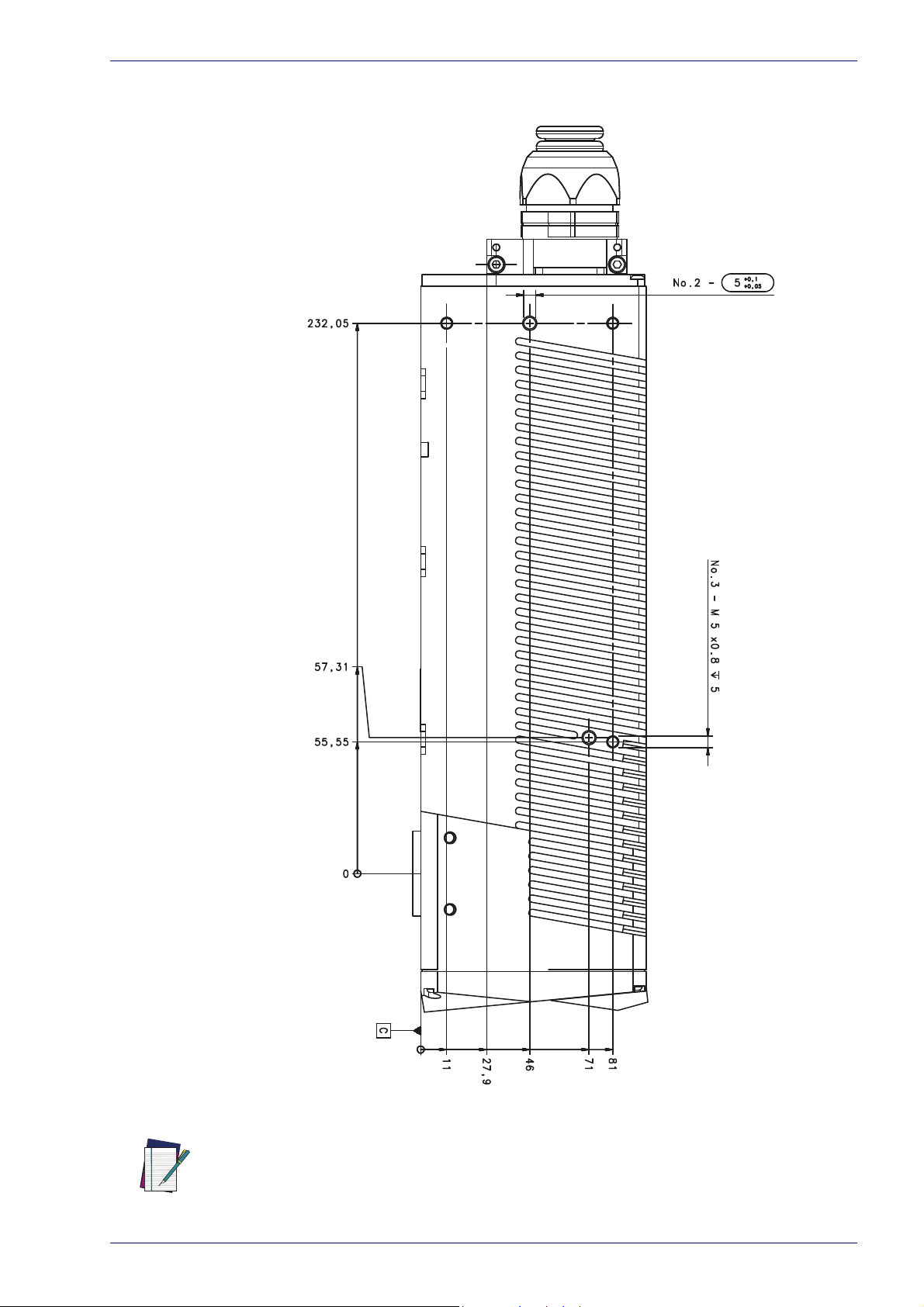
It is also possible to mount the scan head sideways using dedicated threaded
holes:
Figure 12: Fixing points on scan head side
All dimensions are in millimeters.
NOTE
User Manual 13
Page 28

Installation
Scan Head
4 mm
Mounting plate thickness
Washer thickness
M5 screw
Scan head mounting screws length
To determine the length of the mounting screws, consider the thickness of the
mounting plate and the thickness of the washer.
Figure 13: Length of mounting screws
Mounting holes depth is =4mm. Tightening torque = 2 Nm.
NOTE
14
Arex™ 400
Page 29
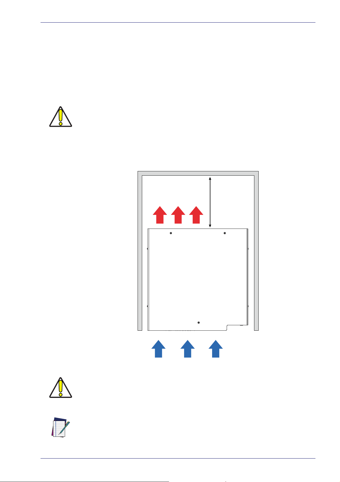
Installation environment
≥300mm
Control rack
The control rack must be installed in a suitable environment in order to allow
proper air flow and correct housing of the cables.
The control rack uses a forced air cooling system: an adequate air flow is necessary to guarantee its correct cooling. Install the control rack so that air flow is
no
t obstructed. Moreover, do not install it near a heat source.
If not enough space is provided, the temperature inside the control rack could rise,
causing temperature error.
W
ARNING
Clean the air filter when it is dirty. If the air filter is dirty, insufficient air-flow
might not ensure correct cooling and might stop the marking operation. Clean or
replace the air filter periodically.
Installation environment
Figure 14: Control rack installation environment
DO NOT place heavy objects on top of the control rack!
W
ARNING
The control rack IP rating is IP31 in horizontal position, otherwise IP30.
NOTE
User Manual 15
Page 30
Installation
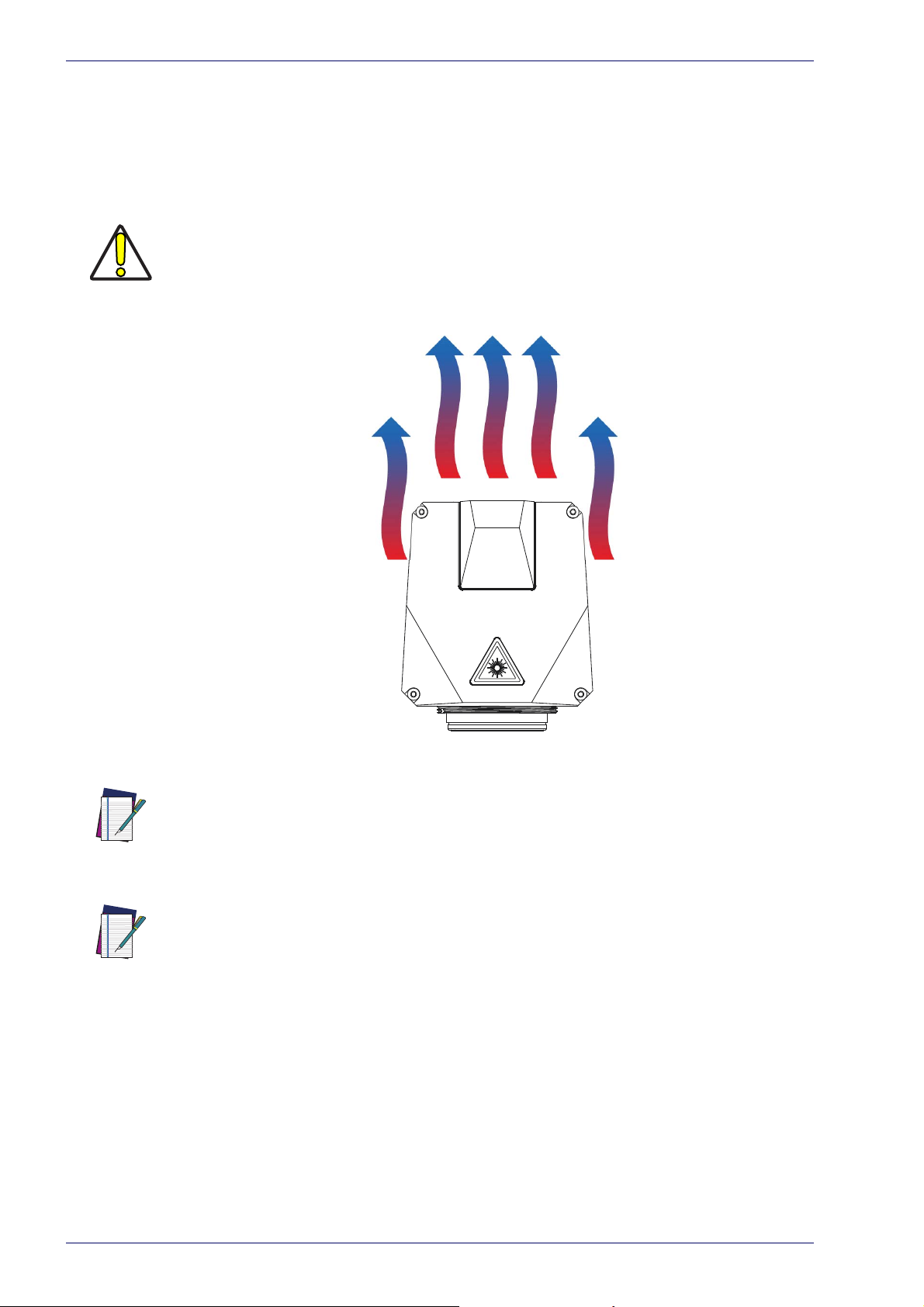
Scan Head
W
ARNING
The scan head must be installed in a suitable environment in order to allow
proper air flow and correct housing of the cables.
The scan head uses a passive air cooling syst
sary to guarantee its correct co
obstructed. Moreover, do not install it near a heat source.
If not enough space is provided, the temperature inside the control rack could rise,
causing temperature error.
oling. Install the scan head so that air flow is not
em: an adequate air flow is neces-
NOTE
NOTE
Figure 15: Scan head installation environment
The scan head IP rating is IP64 not co
To ensure a complete IP64 protection for 160S and
proper accessory (see "
M39 F-Theta protective cap" on page 70).
nsidering F-Theta scan lens.
254S F-Theta scan lenses use the
16
Arex™ 400
Page 31

Fume / Dust extractor
During the marking process, dust and/or fume may be produced. It is important
to use an adequate fume/dust extractor and/or air filtration (see “Fume
Extractor” on page 71).
Marking PVC (or other plastic material) can cause the release of chlorine gas which can
be harmful to the laser operator and to the laser marker itself. Always use adequate
fume extractor during PVC and plastic marking.
W
ARNING
Fume / Dust extractor
User Manual 17
Page 32

Chapter 2
Technical Specifications
TECHNICAL CHARACTERISTICS starting on page 19
PRODUCT DESCRIPTION starting on page 20
MARKING AREA SPECIFICATION starting on page 22
GREEN SPOT starting on page 24
CONNECTORS SPECIFICATIONS starting on page 25
INPUT/OUTPUT SPECIFICATIONS starting on page 34
LASER MARKER STAT ES starting on page 35
TIMING DIAGRAMS starting on page 37
LIGHTER™ SUITE MARKING SOFTWARE starting on page 42
18
Arex™ 400
Page 33

Technical Characteristics
Technical Characteristics
AREX™ 400 MODELS A20-X6X 110-XXX 120-XXX 130-X6X 150-X6X
Electrical specifications
Input Voltage (main power supply) V (AC) 100 to 240 @ 50-60 Hz
Max. Input Current (main power supply) A 3 - 1.25 4 - 1.7
Max power W 300 400
2
4
6
1
(HxWxD)
≥
0.75 1
≥
10 10
°C
°F
°C
°F
5 to 40
41 to 104
-10 to 60
14 to 140
< 90 without condensation
mm
in
Kg
lbs
113x432x434
4.4x17x17.1
17.5
38.5
Forced Air Cooling
Rack fans: L10@ 40°C = 70000 h
Laser source fans: L10@ 40°C = 65000 h
mm
in
Kg
lbs
96x90x326
3.7x3.5x12.8
3.5
7.7
IP64
Air Cooling
mm
in
mm
in
80 (fixed installation); 11
0 (mobile installation)
3.15 (fixed installation); 4.33 (mobile installation)
2885
113.5
High speed galvanometer scanning system
mm/s Up to 10000
char/s Up to 600
m/min
pcs/s
Up to 75
3
EMC (Embedded Marking Control) and Lighter™ Suite
5 to 35
41 to 95
Laser Source specifications
Laser Type Pulsed Fiber Laser
Nominal Average Power W 20 10 20 30 50
Pulse Energy (max.) mJ
Peak Power (max.) kW
Central Emission Wavelength nm 1050-1080 1064
Typical Nominal Pulse Width ns 4 to 250 100
Repetition Rate kHz 20 to 500 2 to 200
Laser Aiming Beam / Focus Beam Class 2: 655 nm
Environmental specifications
Operating temperature
Storage Temperature
Humidity %
Altitude m < 2000
Shock and Vibration MIL 810E ”CAT1 Basic Transportation”
Package Drop Test cm 60
Pollution Degree 2
Overvoltage Category II
Physical specifications
Control Rack dimensions (HxWxD)
Control Rack Weight
Control Rack IP Rating IP31 (in horizontal position, otherwise IP30)
Control Rack Cooling
Scan Head dimensions
Scan Head Weight
3
Scan Head IP Rating
Scan Head Cooling
Noise dB (A) < 65 at 1 meter
Head Cable minimum bending radius
Head Cable Length
Beam deflection
Other specifications
Marking Speed
5
Char Marking Speed
MOF (Marking on the fly) YES [constant speed or encoder]
Line speed - Productivity
Marking Control and Software
Communication RS232, Ethernet (TCP/IP 10, 100 Mbit), Ethernet/IP, digital I/O
1. Specification @ 25°C
2. Without F-Theta scan lens
3. Without F-Theta scan lens
4. Using M39 F-Theta protective cap
5. May vary: measured with f =160mm
6. Single line string, Roman-s font, 1mm height
User Manual 19
Page 34

Technical Specifications
Product Description
Control rack
A description of the main parts of the control rack unit is provided here below:
Figure 1: Control rack overview (front and back panels view)
Front panel:
1. Status LED
2. Start Marking button
3. Key Selector
4. 2x USB 2.0 ports
Back panel:
5. Main Power Supply connection
6. Safety Circuit connector
7. VGA port
8. RS232 port
9. Encoder connector
10. Photocell connector
11. I/O connector (Axes Control)
12. Command Box connector (Laser Control)
13. Head Cable
14. Device Port 2
15. Device Port 1
16. LAN 1 port
17. LAN 3 port (
18. LAN 2 port (
19. 4x USB 2.0 ports
20. Earth ground connection
only for XXX-X6X models
only for XXX-X6X models
)
)
20
Arex™ 400
Page 35

Scan head
Product Description
A description of the main parts of the scan head unit is provided here below:
Figure 2: Scan head overview (front, rear and bottom view)
1. Status LED
2. F-Theta Scan Lens
3. External Focus Beam connector
4. Head Cable
5. Focusing Beam output
6. IR laser beam output / Aiming laser beam output / Green Spot beam output
User Manual 21
Page 36

Technical Specifications
Marking Area Specification
Datalogic provides a wide range of laser marker models with different F-Theta
scan lenses configurations.
These configurations are provided to best match customer needs regarding
rking field size, working distance and power density.
ma
Contact Datalogic if other configurations are necessary.
NOTE
Definition of Marking Area:
• Arex™ 110-XXX/120-XXX/A20-X6X: square marking field measured on black
anodized aluminium plate.
NOTE
• Arex™ 130-X6X/150-X6X: square marking field within which power is > 95% with
resp
ect to power in center.
only certain configurations of F-Theta scan lens and
talogic provides a specific adapter. This
WARNING
W
ARNING
This product was designed to use
marking field. If your needs are not satisfied by the currently available F-Theta scan
lens configurations please contact Datalogic for a solution. The use of other F-Theta
scan lenses or operation outside the specified marking field for a certain F-Theta scan
lens configuration can lead to damage of the F-Theta scan lens, scan head or laser
source. Such damage is not covered by warranty!
For each F-Theta scan lens configuration Da
adapter ensures that residual back reflections caused by the F-Theta scan lens do not
damage the scanning head optics. The removal of such adapter or its incorrect use (for
example incomplete threading, use of another F-Theta scan lens adapter, etc.) can lead
to damage of the F-Theta scan lens, scan head or laser source. Such damage is not
covered by warranty!
F-Theta Scan Lens for Arex™ 110-XXX, 120-XXX and A20-X6X
The table below lists the standard F-Theta scan lenses currently available for
Arex™ 110
F-Theta Scan Lens 160S 254S
Working Distance mm 183 ± 5 280 ± 4
Fixing Distance mm 197 ± 6
Marking Area mm 100 x 100 140 x 140
-XXX, 120-XXX and A20-XXX:
F-Theta Scan Lens diameter: M39
300 ± 5
22
F-Theta Scan Lens diameter: M85 (
F-Theta Scan Lens 100L 330L(*) 420L(*)
Working Distance mm 99 ± 3 388 ± 6 492 ± 6
Fixing Distance mm 141 ± 4 471 ± 7
Marking Area mm 50 x 50 220 x 220 285 x 285
(*) NOT AVAILABLE for 110-X6X
available only for XXX-X6X versions
561 ± 7
)
Arex™ 400
Page 37

F-Theta Scan Lens for Arex™ 130-X6X and 150-X6X
WD: Working Distance
FD: Fixing Distance
MA: Marking Area
AB: Aiming Beam
FB: Focusing Beam
The table below lists the standard F-Theta scan lenses currently available for
Arex™ 130-X6X and 150-X6X:
F-Theta Scan Lens diameter: M85
F-Theta Scan Lens 160L 254L 330L
Working Distance mm 176 ± 2 296 ± 5 388 ± 6
Fixing Distance mm 212 ± 3 367 ± 6
Marking Area mm 100 x 100 170 x 170 210 x 210
Working Distance is defined as the distance between the center of the marking area
(defined in the focal plane) and the closest mechanical edge of the F-Theta scan lens.
Refer to the following figure.
NOTE
Marking Area Specification
471 ± 7
NOTE
Fixing Distance is defined as the distance be
marking area. Refer to the following figure.
tween the base of the scan head and the
NOTE
User Manual 23
Figure 3
For products equipped with 160S, 254S, 160L and
position, defined at the point where the focus beam overlaps with the aiming beam, is
preset at factory.
: Marking Area
100L F-Theta scan lenses the focus
Page 38

Technical Specifications
Green Spot
The Green Spot is an indicator integrated in the scan head able to provide a
green visual feedback in the center of marking field area.
CONFIGURATION
OFF
SYSTEM READY TO MARK
MARKING CONFIRMATION
MARVIS VERIFICATION
1
Figure 4: Green Spot indicator
DESCRIPTION
The Green Spot indicator is not active (always OFF)
The Green Spot is steady ON only when all these events are verified:
- the laser marker is in READY state
- a document is in AUTO MODE or WORK MODE
- the marking process is not in progress
The Green Spot turns ON when all these events are verified:
- the laser marker is in READY state
-
a document is in AUTO MODE or WORK MODE
- the marking process was correctly executed (no errors, no
stop marking, no state changing)
The Green Spot indicator turns ON at the end of the marking process and
stay active for a configurable range of time from 0.1s to 5s
This is available only if MARVIS™ feature is enabled.
The Green Spot turns ON when all these events are verified:
- the laser marker is in READY state
a document is in AUTO MODE or WORK MODE
-
- the marking process was correctly executed (no errors, no
stop marking, no state changing)
- the verification of the marking content made by MARVIS™
device was positive
The Green Spot indicator turns ON at the end of the marking process and
s
tay active for a configurable range of time from 0.1s to 5s
24
1. refer to Lighter™ user's manual “Setting I/O parameters” paragraph to set the signal properties
Arex™ 400
Page 39

Connectors Specifications
Connectors Specifications
Safety Circuit
Control rack back panel connector
Socket Sub-D, 15 pins, female.
Figure 5: Safety Circuit connector, female panel plug (front view)
PIN SIGNAL TYPE DESCRIPTION
1 VCC Power Output Auxiliary 24V DC power supply
2 RESERVED - DO NOT CONNECT
3 VCC Power Output
4 SAFETY_FDBK+ Output Clean contact pole for monitor K relays state (Common)
5 SAFETY_FDBK- Output
6 GND Ground Ground reference
7 RESERVED 8 GND Ground Ground reference
9 INTERLOCK_A Input
10 RESERVED - DO NOT CONNECT
11 INTERLOCK_B Input
12 RESERVED - DO NOT CONNECT
13 LASER_STOP_A Input
14 RESERVED - DO NOT CONNECT
15 LASER_STOP_B Input Return signal for K2 relay coil (
Auxiliary 24V DC power supply
Return of clean contact pole for monitor
mally Closed)
DO NOT CONNECT
Interlock signal for K1 relay coil
Interlock signal for K2 relay coil (
Return signal for K1 relay coil
only for XXX-X6X models
only for XXX-X6X models
K relays state (Nor-
)
)
Table 1: Safety Circuit connector pinout
User Manual 25
Page 40

Technical Specifications
for XXX-X5X models
for XXX-X6X models
Safety Circuit Electric Diagram
Figure 6: Safety Circuit connector, electric diagram
TECHNICAL CHARACTERISTICS
Control Contacts
Inrush current max. 15 A for 20 ms
Switching current range
Contact resistance (as delivered) 100 m / 6 V / 100 mA
Standard coils for direct current
Nominal Voltage V DC 24
Min. pick-up voltage at 20°C
Drop-out voltage at 20°C
Nominal current in mA 31.5
Resistance in Ohm at 20°C 760 ± 10%
5 mA to 6 A
16.8
2.4
26
Arex™ 400
Page 41

WARNING
Connectors Specifications
Muting Device
Sub-D, 15 pins, male, with shell.
Figure 7: Safety Circuit Muting Device provided
Do not use the Safety Circuit Muting Device for external devices, since this will result in
loss of the safety function of the machine to which this product is installed.
Do not use the Safety Circuit Muting Device except for maintenance of this product.
W
ARNING
It is the customer's responsibility to provide a correct integration of the safety signals
according to applic
able regulations.
Internal electric diagram
Figure 8: Safety Circuit Muting Device electric diagram
User Manual 27
Page 42

Technical Specifications
Command Box (Laser Control)
Control rack back panel connector
Socket Sub-D, 25 pins, female.
Figure 9: Command Box connector, female panel socket (front view)
PIN SIGNAL TYPE (***) DESCRIPTION
1 24V_ENABLE_B Output power supply Auxiliary 24V DC power supply available for
Secondary external ENABLE signal:
2 EXT_ENABLE_B Digital Input
3 GOOD/BAD Digital Output
4 EXT_24V Output power supply Auxiliary 24V DC power supply available for drive input logical HIGH (max 125mA)
5 EXT_24V Output power supply
6 EXT_24V Output power supply Auxiliary 24V DC power supply available for drive input logical HIGH (max 125mA)
7 24V_ENABLE_A Output power supply
8 EXT_ENABLE_A Digital Input
9 BUSY Digital Output
10 CONNECTOR_PRESENCE Digital Input
11 START_MARKING (*) Digital Input
12 EXT_KEY Digital Input
13 STOP_MARKING (*) Digital Input
14 RESERVED - DO NOT CONNECT
15 RESERVED 16 RESERVED - DO NOT CONNECT
17 END Digital Output
18 POWER_ON Digital Output
19 GND Ground
20 SYSTEM_ALARM Digital Output
21 GND Ground
22 ENABLE_OUT Digital Output
23 SW_READY (*) Digital Output
24 GND Ground Ground reference
25 GND Ground Ground reference
- HIGH level: contact closed
- LOW level or disconnected: contact opened
This signal is used to notify a bad marking:
- ON in case of bad marking
Auxiliary 24V DC power supply available for drive input logical HIGH (max 125mA)
Auxiliary 24V DC power supply available for
Primary external ENABLE signal:
- HIGH level: contact closed
- LOW level or disconnected: contact opened
This signal is used to know if the current
- ON during marking process
This signal is used to check the presence of the Command Box connector:
- HIGH level: normal operation
- LOW level or disconnected: laser marker faulty
This signal is used to start to the marking process when a docum
ning in AUTO MODE (**) or WORK MODE (**):
- HIGH level pulsed signal start the marking process
External KEY signal:
- HIGH level: contact closed
- LOW level or disconnected: contact opened
This signal is used to stop the marking process:
- HIGH level pulsed signal stop the marking process
DO NOT CONNECT
This signal is used to know if the marking process is finished:
- ON at the end of marking process
This signal is used to know if the laser marker is already warmed up:
- ON when the laser is in STAND_BY or READY state
Ground reference
This signal is used to know if the laser marker is in booting up state or in error state:
- ON during BOOTING UP
- ON in case of system error
Ground reference
This signal is used to know if the laser marker is ready to emit laser radiation:
- ON when the laser marker is in READY state
Depending on the configuration this signal can be used in different ways:
- COMPATIBILITY: ON when a document or a sequence is running in AUTO MODE (**) or
RK MODE (**) independently from the laser marker state. The signal is ON regardless
WO
of whether the laser marker is ready to start a new marking
- STANDARD: ON when a document or a sequence is running in AUTO MODE (**) or WORK
MOD
E (**) and the laser marker state is READY. The signal is ON regardless of whether
the laser marker is ready to start a new marking
- READY TO MARK: ON only when a document or a sequence is running in AUTO MODE (**)
o
r WORK MODE (**) and the laser marker state is READY. The signal is ON only if the laser
marker is ready to accept a new START_MARKING event (loading/spooling already executed)
This signal can also be driven using Lighter™ Script engine "IoPort.setReady (true)" function
EXT_ENABLE_B
EXT_ENABLE_A
spooler is executing (marking in progress):
(max 125mA)
(max 125mA)
ent or a sequence is run-
28
Table 2: Command Box connector pinout
(*) refers to Lighter™ user's manual “Setting I/O parameters” paragraph to set the signal properties
(**) refers to Lighter™ user's manual
(***) see “Input/Output specifications” on page 34
Arex™ 400
Page 43

W
ARNING
Connectors Specifications
Muting Device
Sub-D, 25 pins, male, with shell.
Figure 10: Command Box Muting Device provided
If the Command Box Muting Device provided is connected, the laser marker enable is
bypassed.
Internal electric diagram
Figure 11: Command Box Muting Device electric diagram
User Manual 29
Page 44

Technical Specifications
Axes (I/O Control)
Control rack back panel connector
Plug Sub-D, 25 pins, male.
Figure 12: Axes connector, male panel plug (front view)
PIN SIGNAL(**) TYPE (***) DESCRIPTION
1 EXT_24V
2 OUTPUT_0 (*) or STEP_Y Digital Output Generic output or Y-Axis drive step signal (Clock) for axis control (**)
3 OUTPUT_2 (*) or STEP_Z Digital Output
4 OUTPUT_4 (*) or BRAKE X Digital Output
5 OUTPUT_6 (*) or BRAKE Y Digital Output
6 OUTPUT_8 (*) or BRAKE Z Digital Output
7 INPUT_0 (*) or ZERO X Digital Input
8 INPUT_1 (*) or ZERO Y Digital Input
9 INPUT_2 (*) or ZERO Z Digital Input
10 INPUT_3 (*) or DISABLE X Digital Input
11 INPUT_4 (*) or DISABLE Y Digital Input
12 INPUT_5 (*) or DISABLE Z Digital Input
13 GND Ground
14 OUTPUT_12 (*) or STEP R Digital Output Generic output or R-Axis drive step signal (Clock) for axis control
15 OUTPUT_1 (*) or STEP X Digital Output
16 OUTPUT_3 (*) or DIR Z Digital Output Generic output or Z-Axis drive direction signal
17 OUTPUT_5 (*) or DIR Y Digital Output
18 OUTPUT_7 (*) or DIR X Digital Output Generic output or X-Axis drive direction signal
19 INPUT 9 Digital Input
20 INPUT 8 Digital Input Generic Input
21 INPUT_7 (*) or ZERO R Digital Input
22 INPUT_6 (*) or DISABLE R Digital Input
23 OUTPUT_9 (*) or BRAKE R Digital Output
24 OUTPUT_11 (*) or DIR R Digital Output Generic output or R-Axis drive direction signal
25 GND Ground Ground reference
Output Power
supply
Auxiliary 24V DC power supply available for drive input logical HIGH
(max 125mA)
Generic output or Z-Axis drive step signal (Clock) for axis control (**)
Generic output or X-Axis electromechanical brake release signal. ON
during drive motion
Generic output or Y-Axis electromechanical brake release signal. ON
during drive motion
Generic output or Z-Axis electromechanical brake release signal. ON
during drive motion
Generic input or X-Axis home sensor input. The home search is
stopped when this signal goes HIGH
Generic input or Y-Axis home sensor input. The home search is
stopped when this signal goes HIGH
Generic input or Z-Axis home sensor input. The home search is
stopped when this signal goes HIGH
Generic input or X-Axis disable signal. When HIGH, the correspond-
ing step signal remains in the state prior to activation
Generic input or Y-Axis disable signal. When HIGH, the corresponding
step signal remains in the state prior to activation
Generic input or Z-Axis disable signal. When HIGH, the correspond-
ing step signal remains in the state prior to activation
Ground reference
Generic output or X-Axis drive step signal (Clock) for axis control
Generic output or Y-Axis drive direction signal
Generic Input
Generic input or R-Axis home sensor input. The home search is
stopped when this signal goes HIGH
Generic input or R-Axis disable signal. When HIGH, the corresponding step signal remains in the state prior to activation
Generic output or R-Axis electromechanical brake release signal. ON
during drive motion
30
Table 3: Axes Connector pinout
(*) enabling an axis causes the corresponding control signals to no longer be available as generic inputs/outputs. Refer to
Lighter™ user's manual, "Setting the X, Y, Z, and Rotor Axes parameters" to enable/disable Axes and set the Axes properties
(**) see “Axes I/O signals behavior” on page 41
(***) see “Input/Output specifications” on page 34
Arex™ 400
Page 45

Connectors Specifications
Encoder
Control rack back panel connector
Socket, M12, 8 pins female. Recommended encoder: Datalogic ENC58-S10XXXX-M12 (ENC58-S10-5000-M12). See “Starter Kit for Marking On the Fly
(MOF)” on page 71.
Figure 13: Encoder connector, female panel socket (front view)
PIN SIGNAL TYPE (*) DESCRIPTION
1 GND Ground Ground reference
2 VCC Power Output Auxiliary 24V DC power supply (750mA max)
3 ENC_A Digital input
4 GND Ground Return signal for ENC_A
5 ENC_B Digital Input
6 GND Ground Return signal for ENC_B
7 RESERVED 8 RESERVED - DO NOT CONNECT
BODY SHIELD Shield Shield
Encoder HTL A channel signal
Encoder HTL B channel signal
DO NOT CONNECT
Table 4: Encoder connector pinout
(*) see “Input/Output specifications” on page 34
Photocell
Control rack back panel connector
Socket, M12, 4 pins female. Recommended photocell: Datalogic S51-PA-5-B01PK; Datalogic S15-PA-5-B01-PK or equivalent. See “Starter Kit for Marking On
the Fly (MOF)” on page 71.
Figure 14:Photocell connector, female panel socket (front view)
PIN SIGNAL TYPE (*) DESCRIPTION
1 VCC Power Supply Auxiliary 24V DC power supply (120mA max)
2 RESERVED - DO NOT CONNECT
3 GND Ground
4 PHOTOCELL Digital input PNP photocell signal
Ground reference
Table 5: Photocell connector pinout
(*) see “Input/Output specifications” on page 34
User Manual 31
Page 46

Technical Specifications
Device Port 1
Control rack back panel connector
Plug, M12, 8 positions male.
Figure 15: Device Port 1 connector, male panel plug (front view)
PIN SIGNAL TYPE (*) DESCRIPTION
1 VCC Power Output Auxiliary 24V DC power supply (15W max power)
2 GND Ground Ground reference
3 EXT_TRIG_#1 Digital Output
4 EXT_INPUT_#1 Digital Input Reserved input for MARVIS™
5 RESERVED 6 INT_RS232_RX Digital Input Reserved RS232 for micrometric distance sensor
7 INT_RS232_TX Digital Output
8 RESERVED - DO NOT CONNECT
BODY SHIELD Shield Connector case provides
Reserved output for MARVIS™
DO NOT CONNECT
Reserved RS232 for micrometric distance sensor
electrical connection to the body
Table 6: Device Port 1 connector pinout
(*) see “Input/Output specifications” on page 34
Device Port 2
Control rack back panel connector
Plug, M12, 8 positions male.
Figure 16: Device Port 2 connector, male panel plug (front view)
PIN SIGNAL TYPE (*) DESCRIPTION
1 VCC Power Output Auxiliary 24V DC power supply (15W max power)
2 GND Ground Ground reference
3 EXT_TRIG_#2 Digital Output
4 EXT_INPUT_#2 Digital Input Reserved input for MARVIS™
5 RESERVED 6 RESERVED - DO NOT CONNECT
7 RESERVED 8 RESERVED - DO NOT CONNECT
BODY SHIELD Shield Connector case provides
Reserved output for MARVIS™
DO NOT CONNECT
DO NOT CONNECT
electrical connection to the body
32
Table 7: Device Port 2 connector pinout
(*) see “Input/Output specifications” on page 34
Arex™ 400
Page 47

RS232 (COM3)
Control rack back panel connector
Plug Sub-D, 9 pins, male.
Figure 17: RS232 connector, male panel plug (front view)
PIN SIGNAL TYPE DESCRIPTION
1 DCD Input Data Carrier Detect
2 RXD Input Receive Data
3 TXD Output
4 DTR Output Data Terminal Ready
5 GND Ground
6 DSR Input Data Set Ready
7 RTS Output
8 CTS Input Clear To Send
9 RI Input Ringing Indicator
Transmit Data
Ground reference
Request To Send
Connectors Specifications
Table 8: Standard RS232 connector pinout
Ext Focus
Scan head connector
Socket, M8, 4 pins female.
Figure 18: Ext Focus connector, female socket (front view)
PIN SIGNAL TYPE DESCRIPTION
1 EXT_FOCUS+ Power Output Reserved Auxiliary power supply for focusing beam
2 EXT_FOCUS- Ground Reserved ground for focusing beam
3 RESERVED 4 RESERVED - DO NOT CONNECT
DO NOT CONNECT
User Manual 33
Page 48

Technical Specifications
USING EXTERNAL POWER SUPPLY
USING AUXILIARY POWER SUPPLY
USER SIDE
USER SIDE
LASER MARKER SIDE
LASER MARKER SIDE
USING EXTERNAL POWER SUPPLY
USING AUXILIARY POWER SUPPLY
USER SIDE
USER SIDE
LASER MARKER SIDE
LASER MARKER SIDE
Input/Output specifications
Digital Input
TECHNICAL CHARACTERISTICS
Type
Vmax
Imax
Pulse Width
INPUT Logic LOW
INPUT Logic HIGH
Optocoupler
28 V DC
10 mA @ 24 V DC
≥ 1ms (debounce)
MIN TYP
0.0 V DC 0.0 V DC 2.0 V DC
10.0 V DC 24.0 V DC 28.0 V DC
MAX
Table 9: Digital Input specification
Digital Output
TECHNICAL CHARACTERISTICS
Type Low side driver
Vmax 24 V DC
Imax
LOW Level Output V ≤ 0.5 V DC; I ≤ 250mA
HIGH Level Output V
Table 10: Digital Output specification
250 mA
≤ 24 V DC; I ≤ 5μA
34
Arex™ 400
Page 49

Laser Marker States
Laser Marker States
Normal Operation States
STATE DESCRIPTION STATUS LED
SYSTEM BOOTING UP
WAIT FOR START
STANDBY SHUTTER CLOSED
READY In this state the laser marker is able to emit IR laser radiation
This state occurs since the laser marker
Engine has been loaded and no errors occurred
In this state the laser marker cannot emit IR lasers radiation and Aiming
and Focus beam cannot be activated
In this state Aiming and Focus beam can be activated while the laser
marker cannot
emit IR laser radiation
is switched on until Laser
Blinking
Steady
Steady
Steady
Error States
STATE DESCRIPTION STATUS LED
ERROR
SYSTEM ERRORS DESCRIPTION
INTERLOCK ERROR
CBOX ERROR
RACK TEMPERATURE ERROR
SCANHEAD TEMPERATURE
ERROR
SCANHEAD CONNECTION
ROR
ER
This state occurs if the laser marker detects an error that prevents normal operation
This error rise if the INTERLOCK function is ON. To reset the error, set INTERLOCK function
to OFF and repeat the turning on sequence
This error rise if the
LOW or not connected. To reset the error, set
and repeat the turning on sequence
This error rise if the temperature inside the control rack is out of the operating temperature range. To reset the error, a Laser marker restart is required
This error rise if the temperature inside the scan head is out of the operating temperature
range. To reset the error, a Laser marker restart is required
This alarm rise if the cable between control rack and scan head is not connected. To reset
the error, a Laser marker restart is required
CONNECTOR_PRESENCE
signal (pin 10 Command Box connector) is
CONNECTOR_PRESENCE
signal to HIGH value
Blinking
LASER SOURCE ERRORS DESCRIPTION
TEMPERATURE ERROR
POWER SUPPLY ERROR
BACK REFLECTION ERROR
GENERIC ERROR
This error rise if the temperature inside the laser source is out of the operating temperature range. To reset the error, a Laser marker restart is required
This error rise if the power supply of the laser source is out of range. To reset the error, a
Laser marker restart is required
This error rise if high optical power is reflected back to the laser source. To reset the error, a
Laser marker restart is required
This error rise if the laser source detects an internal failure. To reset the error, a Laser
marker restart is required
Warning State
STATE DESCRIPTION STATUS LED
WARNING INVALID START
SEQUENCE
User Manual 35
This state occurs if the turning on sequence has not been followed. To
restore normal laser marker operation, repeat the turning on sequence
Blinking
Page 50

Technical Specifications
Control the Laser Marker States
The laser marker states can be controlled by:
• Key Selector
• Command Box connector
Key Selector mode
Controlling the laser marker states using the Key Selector on the control rack
front panel requires that the input signals of the command box connector
EXT_KEY, EXT_ENABLE_A
STATE COMMAND BOX INPUT STATE KEY SELECTOR STATUS LED
SYSTEM BOOTING UP
WAIT FOR START
STANDBY SHUTTER CLOSED
READY (*)
and
EXT_KEY
EXT_ENABLE_A
EXT_ENABLE_B
EXT_KEY
EXT_ENABLE_A
EXT_ENABLE_B
EXT_KEY
EXT_ENABLE_A
EXT_ENABLE_B
EXT_KEY
EXT_ENABLE_A
EXT_ENABLE_B
EXT_ENABLE_B
are set to fixed HIGH level:
HIGH
HIGH
HIGH
HIGH
HIGH
HIGH
HIGH
HIGH
HIGH
HIGH
HIGH
HIGH
Blinking
Steady
Steady
Steady
(*)
LASER_STOP
safety function not active
Command Box mode
Controlling the laser marker states using the Command Box connector on the
control rack back panel requires that the Key Selector is set to fixed position
LASER ON:
STATE COMMAND BOX INPUT STATE KEY SELECTOR STATUS LED
SYSTEM BOOTING UP
WAIT FOR START
STANDBY SHUTTER CLOSED
READY (*)
(*)
LASER_STOP
safety function not active
EXT_KEY
EXT_ENABLE_A
EXT_ENABLE_B
EXT_KEY
EXT_ENABLE_A
EXT_ENABLE_B
EXT_KEY
EXT_ENABLE_A
EXT_ENABLE_B
EXT_KEY
EXT_ENABLE_A
EXT_ENABLE_B
LOW
LOW
LOW
LOW
LOW
LOW
HIGH
LOW
LOW
HIGH
HIGH
HIGH
Blinking
Steady
Steady
Steady
36
Arex™ 400
Page 51

Timing Diagrams
typ 60s
user
defined
within
50ms
user
defined
within
50ms
T1
T2
T3
T4
T5
T6
Turning On sequence
Timing Diagrams
Figure 19: Turning On sequence timing diagram
Marking control signals behavior
Figure 20: Marking process timing diagram
NOTE
REF. NAME
T1 Start Time
T2 Start Delay
T3 Busy Advance
T4 Stop Time
T5 Busy Delay
T6 End Time Time duration of the
Consult Lighter™ software user's manual for a proper use of the same.
DESCRIPTION
Minimum time duration that the
have in order to be accepted as a valid START_MARKING event
Delay between the acceptance of the
the rising edge of the
Delay between the rising edge of the
emission
Minimum time duration that the
in order to be accepted as a valid STOP_MARKING event
Delay between the end of the laser emission and the falling edge of
BUSY
signal
the
BUSY
END
signal
signal
START_MARKING
START_MARKING
BUSY
signal and the laser
STOP_MARKING
signal must have
signal must
signal and
User Manual 37
Page 52

Technical Specifications
Bad marking event
Error event
SW_Ready output signal (Ready to Mark mode)
Figure 21: SW_Ready signal timing diagram
Good\Bad output signal
Figure 22: Good\Bad signal timing diagram
System_Alarm output signal
Figure 23: System Alarm timing diagram
38
Arex™ 400
Page 53

MARVIS™ I/O signals behavior
within 50ms
user defined
within 600ms
user defined
within 50ms
within 600ms
Figure 24: MARVIS™ I/O signals behavior
Timing Diagrams
Safety functions behavior
Interlock behavior
Laser_Stop behavior
Figure 25: Interlock behavior
Figure 26: Laser_Stop behavior
User Manual 39
Page 54

Technical Specifications
0.1s to 5s
0.1s to 5s
Green Spot behavior
System Ready to Mark mode
Marking Confirmation mode
Figure 27: Green Spot: System Ready to mark
Figure 28: Green Spot: Marking Confirmation
MARVIS Verification mode
Figure 29: Green Spot: MARVIS™ Verification
40
Arex™ 400
Page 55

Axes I/O signals behavior
T2
T2
T1
Timing Diagrams
Figure 30: Axes I/O signals behavior
REF. NAME
T1 Brake release
T2 Ramp Time
DESCRIPTION
The time that elapses between the brake release signal activation
and the start of mechanical movement
The time to go from minimum speed (Start speed) to working speed
(Speed)
User Manual 41
Page 56

Technical Specifications
Lighter™ Suite marking software
The laser marker is equipped with Lighter™ Suite marking software.
Lighter™ Suite is the all-inclusive editing and laser management software for all
Da
talogic Laser Marking products.
Lighter™ Suite with its innovative approach focused on the user experience is
re
volutionizing Laser Marking management; the powerful and simple interface,
the flexible and comprehensive customization capabilities and effective production tools represent an important step-ahea
trial applications.
Lighter™ Suite combines into an unified GUI (Graphical User Interface) a powerful
ctorial graphical editor, an advanced laser controller and the innovative MAR-
ve
VIS™ (MArk Read Verify Integrated Solution) featur
AutoID code reader for in-line validation of marked traceability codes.
MARVIS™ connects Datalogic MATRIX™ N-seri
enabling controlling from one single interface and enhancing individual products’ performances.
MARVIS™ is also available as update for
Object-Oriented Configuration
In the Lighter Suite, each object is associated with specific LASER parameters and
READER configuration; loading a graphical layout will automatically retrieve and
update laser and reader configurations.
d in traceability and branding indus-
e to seamless interact with
es reader with the laser marker,
existing products.
Advanced Editing Function
MARVIS™ Integrated Configuration And Setup
• Easily create, import and edit texts,
shapes and logos
• One-click code generator for 1D and
2D symbologies
• Object-related Property Browser for
fast adjustment of Marker and Reader
parameters
• Imports Bitmap and Vector files
(DXF, DWG, PLT, PDF, AI, SVG, BMP,
JPG, PNG and TIFF…)
• Advanced filling featured with various laser-optimized patterns
•IP address discovery and connection
management
Dedicated Digital output for in-line
•
parts selection
• Dedicated Digital input for deferred
reader trigger
• Configurable images storage pool
• New Code Quality Training feature to
automatically define code quality
threshold from “Golden Sample”
• Patent Pending “Quality Grade Metric Profile” (QGP)
42
Arex™ 400
Page 57

Lighter™ Suite marking software
Connectivity
The Lighter™ Suite allows OEMs and Machine builders to develop a complete and
cost effective Laser Marking Station, based on embedded hardware and software
resources (such as STAND ALONE mode) or to design an advanced Laser Marking
Solution able to control machinery over a simple Ethernet connection with a
supervisor computer (MASTER-SLAVE mode).
Lighter™ Suite natively embeds Ethernet TCP/IP and EtherNet/IP protocols.
Scripting programmability
The LIGHTER Suite integrates the IDE (Integrated Development Environment)
providing the users with a full set of tools to be used for extremely flexible customization.
The programming language is ECMAScript (also called JavaScript).
• Control the entire marking process
• Create and fully customize marking
layout and its content at runtime
• Interact with local or centralized
databases
• Create alternative customized interfaces
• Interact with Third Party devices
Runtime Production Statistics and Reports
Built-in validation statistics dashboard.
Configurable log file with Quality
Reporting
and code images.
User Manual 43
Page 58

Chapter 3
Installation and set up
CONNECTIONS starting on page 45
F-THETA SCAN LENS PROTECTION CAP REMOVAL starting on page
49
44
Arex™ 400
Page 59

Connections
The laser marker connections are described here below. Follow the operations as
described.
Control rack and scan head are joined by a connection cable 3 meters long. Control rack
and scan head are NOT separable.
W
ARNING
Connecting Command Box connector
The Command Box connector must always be inserted with properly signals provided in order to use the laser marker. The absence of such connector blocks the
aser marker operations.
l
Connections
W
ARNING
If the Command Box Muting Device provided is connect
bypassed.
ed, the laser marker enable is
Figure 1: Connecting Command Box connector
User Manual 45
Page 60

Installation and set up
Connecting Safety Circuit connector
The Safety Circuit connector must always be inserted with properly signals provided in order to use the laser marker. The absence of such connector blocks the
laser emission.
Do not use the Safety Circuit Muting Device for external devices, since this will result in
loss of the safety function of the machine to which this product is installed.
W
ARNING
W
ARNING
NOTE
Do not use the Safety Circuit Muting Device except for maintenance oh this product.
It is the customer's responsibility to provide a correct inte
according to applicable regulations.
Appendix B Understanding SLO: Safe Laser Off" on page 84 about the compli-
See "
ance to safety.
gration of the safety signals
46
Figure 2: Connecting Safety connector
Arex™ 400
Page 61

Connecting Power Supply cable
Connect the Power Supply cable using the cord retention system.
The locking mechanism is released again by pressing the release lever. Thanks to its
luminous bright yellow color, it is easily recognizable and distinguishes this system
from conventional mains connections.
NOTE
Connections
Figure 3: Connecting Power Supply cable
Connecting the Earth Ground
To ensure high electrical noise immunity it is strongly recommended to connect
the chassis to suitable earth ground.
Figure 4: Connecting the Earth Ground
User Manual 47
Page 62

Installation and set up
Local Mode Control connections
To use the laser marker in “Local Mode Control” it is necessary to install a
mouse, keyboard and monitor. Connect the monitor and input devices to laser
marker as shown below:
Figure 5: Connecting the mouse
NOTE
Figure 6: Connecting the keyboard
Figure 7: Connecting the monitor
Minimum monitor resolution 800 x 600 (VGA standard).
48
Arex™ 400
Page 63

Remote Mode Control connection
To use the laser marker in “Remote Mode Control” it is necessary to connect a
network cable:
Figure 8: Connecting LAN port
The LAN ports are configured by default with a fixed IP Address and Subnet Mask:
- LAN 1 Default IP address: 192.168.1.10
F-Theta scan lens protection cap removal
NOTE
NOTE
- LAN 2 Default IP address: 192.168.3.10 (
- LAN 3 Default IP address: 192.168.0.10 (
- Default Subnet Mask: 255.255.255.0
See "
Change the LAN configuration and IP address" on page 60 in order to change
LAN configuration.
Ethernet TCP/IP 10, 100 Mbit.
available only for XXX-X6X models
available only for XXX-X6X models
F-Theta scan lens protection cap removal
Remove the F-Theta scan lens protection cap before marking operation:
)
)
Figure 9: F-Theta scan lens protection cap removal
Marking with the lens protection cap in place could result in damage to the laser
marker.
W
ARNING
User Manual 49
Page 64

Use and operation
FIRST TIME BOOT starting on page 51
TURNING ON SEQUENCE starting on page 52
Chapter 4
50
Arex™ 400
Page 65

First time boot
Before turning on the laser marker, be sure that the laser marker is connected as
previously described. Check the presence of:
•Voltage power supply connection
• Safety Circuit connection
• Command Box connection
Do not use the Safety Circuit Muting Device for external devices, since this will result in
loss of the safety function of the machine to which this product is installed.
W
ARNING
W
ARNING
W
ARNING
Do not use the Safety Circuit Muting Device except for maintenance oh this product.
It is the customer's responsibility to provide a correct integration of the safety signals
according to applic
If the Command Box Muting Device provided is connect
bypassed.
First time boot
The first time the laser marker is turned on after it
the operating system will be restarted within a few seconds.
NOTE
able regulations.
ed, the laser marker enable is
has been unpacked, it warns that
Wait for the shutdown of the operating system.
W
ARNING
W
ARNING
DO NOT turn OFF or UNPLUG the laser marker while Windows®
is shutting down.
User Manual 51
Page 66

Use and operation
Turning On sequence
The laser marker states can be controlled by:
• Key Selector
• Command Box connector
Sequence using Key Selector
Controlling the laser marker states using the Key Selector on the control rack front
panel requires that the input signals of the command box connector
W
ARNING
EXT_ENABLE_A
Turn ON the main power supply switch in the back panel of the control rack. The
laser marker turn on and goes in booting-up state:
and
EXT_ENABLE_B
are set to fixed HIGH level.
EXT_KEY
,
Figure 1: Power on the laser marker
During booting up state, the status LED on the control rack and the status LED
on the scan head blink green.
Wait until booting-up finish: the status LED on the control rack and the status
LED on
state.
the scan head are steady green. The laser marker is in WAIT FOR START
52
Figure 2: Wait for start state
Arex™ 400
Page 67

Rotate the key selector one-step to STANDBY position:
Turning On sequence
Figure 3: Key selector in STANDBY position
The status LED on the control rack and the status LED on the scan head are
steady orange. The laser marker is in STANDBY SHUTTER CLOSED state.
Figure 4: Standby Shutter closed state
User Manual 53
Page 68

Use and operation
Rotate the key selector one-step to LASER ON position:
Figure 5: Key selector in LASER ON position
The status LED on the control rack and status LED on the scan head will turn
red. The laser marker is in READY state.
Figure 6: Ready state
54
Arex™ 400
Page 69

Sequence Using Command Box
Controlling the laser marker states using the Command Box connector on the control
rack back panel requires that the Key Selector is set to fixed position
W
ARNING
Turn ON the main power supply switch in the back panel of the control rack. The
laser marker turns on and goes in booting-up state. During booting up state, the
status LED on the control rack and the status LED on the scan head blink green.
Wait until booting-up has ended: the status LED on the control rack and the status LED on the scan head are steady green. The laser marker is in WAIT FOR
START state.
Figure 7: Wait for start state
Turning On sequence
LASER_ON
.
Set the Command box input signals as in the table below:
STATE COMMAND BOX INPUT STATE KEY SELECTOR STATUS LED
EXT_KEY
STANDBY SHUTTER CLOSED
The status LED on the control rack and the status LED on the scan head are
steady orange. The laser marker is in STANDBY SHUTTER CLOSED state.
EXT_ENABLE_A
EXT_ENABLE_B
HIGH
LOW
LOW
Steady
Figure 8: Standby Shutter closed state
Set the Command box input signals as in the table below:
STATE COMMAND BOX INPUT STATE KEY SELECTOR STATUS LED
READY
EXT_KEY
EXT_ENABLE_A
EXT_ENABLE_B
HIGH
HIGH
HIGH
Steady
The status LED on the control rack and status LED on the scan head will turn red.
The laser marker is in READY state.
Figure 9: Ready state
User Manual 55
Page 70

Chapter 5
Customize the laser marker software
CHANGE O.S. LANGUAGE AND KEYBOARD LAYOUT starting on
page 57
CHANGE THE LAN CONFIGURATION AND IP ADDRESS starting on
page 60
CHANGE THE VIDEO SETTING starting on page 63
REMOTE DESKTOP CONNECTION starting on page 65
56
Arex™ 400
Page 71

Change O.S. language and keyboard layout
Change O.S. language and keyboard layout
The laser marker allows you to customize the operating system changing the
language used in menus, dialogs and languages you can use to enter text and
keyboard layout.
In order to perform this setting it is necessary to connect mouse, keyboard and monitor
to the laser marker (see "
NOTE
1. Turn OFF and ON the laser marker and wait until booting-up finishes (the
status LED on the control rack and on the scan head must be steady green)
Local Mode Control connections" on page 48).
2. From the main screen click on Start
3. Select Change display language:
> Control Panel
User Manual 57
Page 72

Customize the laser marker software
4. In Keyboards and Languages select and choose the desired language.
5. Select Change keyboards to change your keyboard or input language:
NOTE
6. Now select the default input languages and press OK:
Default keyboard layouts are “US” and “IT”. Add a custom keyboard if necessary.
58
Arex™ 400
Page 73

Change O.S. language and keyboard layout
7. Close all the open windows and double click on shortcut to save-data.bat
icon in the desktop screen
8. A message advises you to restart or shutdown the operating system in
order to permanently save data. Press OK:
9. Shut down the operating system in order to save the new settings:
.
W
ARNING
DO NOT turn OFF or UNPLUG the laser marker while Windows® is shutting down.
10.WAIT until operating system shuts down automatically (black screen)
11.Power off the laser marker to complete installation.
User Manual 59
Page 74

Customize the laser marker software
Change the LAN configuration and IP address
The operating system allows you to change the LAN configuration and IP
address.
In order to perform this setting it is necessary to connect mouse, keyboard and monitor
to the laser marker (see "
NOTE
1. Turn OFF and ON the laser marker wait until booting-up finishes (the status
LED on the control rack and on the scan head must be steady green)
Local Mode Control connections" on page 48).
2. From the main window click on Sta
3. Select View network status and task:
rt > Control Panel
60
Arex™ 400
Page 75

Change the LAN configuration and IP address
4. In the Network and Sharing Center window select Change adapter settings:
5. In the Network Connections window double click on Local Area Connection
icon:
6. In the Local Area Connection Properties window double click on Internet
Protocol Version 4 (TCP/IPv4)
User Manual 61
Page 76

Customize the laser marker software
7. In the Internet Protocol Version 4 (TCP/IPv4) Properties you can change the
IP address and configuration:
8. Close all the open windows and double click on shortcut to save-data.bat
icon in the Desktop window.
9. A message advises you to restart or shutdown the operating system in
order to permanently save data. Press OK:
10. Shut down the operating system in order to save the new settings:
DO NOT turn OFF or UNPLUG the laser marker while Windows® is shutting down.
62
W
ARNING
11.WAIT until operating system shuts down automatically (black screen)
12.Power off the laser marker to complete installation
Arex™ 400
Page 77

Change the video setting
The operating system allows you to change the Video setting.
In order to perform this setting it is necessary to connect mouse, keyboard and monitor
to the laser marker (see "
NOTE
1. Turn OFF and ON the laser marker and wait until booting-up finishes (the
status LED on the rack and on the scan head must be steady green)
Change the video setting
Local Mode Control connections" on page 48).
2. From the main window click on Start
3. Select Adjust screen resolution:
> Control Panel
User Manual 63
Page 78

Customize the laser marker software
4. In the Screen Resolution window select the desired Screen resolution and
Color quality:
5. Close all the open windows and double click on shortcut to save-data.bat
icon in the Desktop window.
6. A message advises you to restart or shutdown the operating system in
order to permanently save data. Press OK:
7. Shut down the operating system in order to save the new settings:
64
W
ARNING
DO NOT turn OFF or UNPLUG the laser marker while Windows® is shutting down.
8. WAIT until operating system shuts down automatically (black screen)
9. Power off the laser marker to complete installation
Arex™ 400
Page 79

Remote desktop connection
To connect the laser marker to a remote Windows® based computer, follow these
steps:
1. Turn on the laser marker
2. Make sure that both laser marker and remote computer are connected to
e LAN
th
Remote desktop connection
3. Click St
Connection
4. Click Options
5. In the Computer list, type the host name or the IP address of the computer
to
6. Type the user name, password, and domain (i
which you have allowed remote access into the corresponding boxes, and
then click Connect
art > All Programs > Accessories, and then click Remote Desktop
which you want to connect
f applicable) of an account to
7. In the Log On to Windows® dialog box that appears, type the password of
the account with remote access privileges into the Password box:
User name: DL
Password: dla
8. In the Lo
that you want, and then click OK.
The remote desktop is display
computer is locked during this session
9. To disconnect the session, click the Cl
and then click OK when you are prompted to disconnect the Windows® session.
g on to list, if applicable, select the domain or remote computer
ed in a window on the desktop. The remote
A
ose button in the session window,
User Manual 65
Page 80

Chapter 6
Accessories
CONTROL BOX starting on page 67
REMOTE STAR T FOOT SWITCH starting on page 67
I/O INTERFACE starting on page 68
DB25-TO-FREE LEADS CABLE starting on page 68
MARVIS™ ADD-ON starting on page 69
MICROMETRIC DISTANCE SENSOR KIT starting on page 70
M39 F-THETA PROTECTIVE CAP starting on page 70
STAR TE R KIT FOR MARKING ON THE FLY (MOF) starting on page
71
RACK HANDLES starting on page 71
FUME EXTRACTOR starting on page 71
66
Arex™ 400
Page 81

The accessories listed here below are described for information purposes only,
and are not necessarily included in the packaging. The minimum contents of the
packaging include the main hardware, cables and keys. For additional information, please see
Control Box
This accessory is used to control the laser marker through the Control Box interface.
The Control Box allows to perform the following functions:
• Changing laser marker state
• Starting and Stopping th
• Showing the marking process state
• Showing the system error state
Control Box
"Contents of the packaging" on page 4.
e marking process
Figure 1: Control Box (ordering no: 985330031).
See "Command Box (Laser Control)" on page 28 for detailed control signal description.
NOTE
Remote Start Foot Switch
This accessory is used to provide the
when the pedal is pressed by the operator.
Figure 2: Remote Start Foot Switch (ordering no: 985350035)
START_MARKING
signal to the laser marker
Refer to Remote Start Foot Switch instruction manual for more information.
NOTE
User Manual 67
Page 82

Accessories
I/O interface
Dedicated to on-site quick and easy termination, PLC interfacing, System Test, I/
O troubleshooting, etc. The DB25 Pass-through Command Box connector allows
the integrator to use the interface as a I/O test tool on previously installed products.
• I/O Monitoring LED
• Easy assembly thanks to screw down termination
• Dry contact outputs
•Dry contact inputs
• DIN rail mounting enclosure
Figure 3: I/O interface (ordering no: 985330032)
Refer to I/O Interface instruction manual for more information.
NOTE
DB25-to-Free Leads Cable
This accessory allows an easier integration of the laser marker: the Command
Box connector signals are all available on the free leads side of the cable, labeled
with cable tags.
68
Figure 4: DB25-to-free leads cable (ordering no. 985350032)
Arex™ 400
Page 83

MARVIS™ Add-on
MARVIS™ is the most advanced MARK and VALIDATE solution for traceability.
The innovative Code Quality Training dramatically simplifies setup in a real production environment. The MARVIS™ Add-on for AREX 400 includes:
• MATRIX™ 300N reader
• Power & signals cable
• EtherNet cable
• MARVIS™ license
MARVIS™ Add-on
Figure 5: MARVIS™ Add-on for Arex™ 400 (ordering no: 937600124)
Refer to MARVIS™ Application Note for more information.
NOTE
MARVIS™ Mounting Bracket
This accessory is used to properly fix the MATRIX™-N and the MARVIS™ LED Ring
Light ID 50mm - White to the scan head in a MARVIS™ application (suitable for
F160S and F254S F-Theta scan lens).
Figure 6: MARVIS™ Mounting Bracket (ordering no: 93ACC1916)
MARVIS™ LED Ring Light ID 50mm - White
This accessory is used as external illuminator in MARVIS™ application (suitable
for F160S and F254S F-Theta scan lens).
Figure 7: LED Ring Light ID (ordering no: 93A051394)
User Manual 69
Page 84

Accessories
Micrometric distance sensor kit
Automatically measure target position displacement from pre-setted focus position, and automatically drive the external (optional) Z-axis stage to the correct
laser head position
• Simplified connectivity with dedicated Device Port 1
• KIT includes sensor, mounting brackets, wires and protecti
Figure 8: Distance sensor (ordering no: 985350037)
ve YAG filter
Refer to Micrometric distance sensor kit instruction manual for more information.
NOTE
M39 F-Theta protective cap
Easy to install, easy to replace; simplifies preventive/periodic maintenance
cleaning operation on F-Theta scan lens and allow no-stop operations.
• Ensure complete IP64 protection
• Protect expensive lens from dust and scratches
• Suitable for 160S and 254S F-Theta scan lenses
70
Figure 9: M39 F-Theta protective cap (ordering no. 985350038)
The Protective Cap guarantees IP64 protection grade.
NOTE
Arex™ 400
Page 85

Starter Kit for Marking On the Fly (MOF)
Starter Kit for Marking On the Fly (MOF)
This accessory is used for the implementation of Marking on the Fly applications.
The Kit includes: encoder, photocell,
Figure 10: Kit MOF (ordering no: 985330027)
cables and plastic reflectors.
Rack Handles
This accessory is used to easily fasten the control rack to the cabinet. The fixing
brackets are equipped with handles for easier handling.
Fume Extractor
This accessory is suitable for collecting and filtering dry and non combustible
types of dust contained in non explosive air mixtures produced during laser
marking.
Figure 11: Rack Handles (ordering no: 985350039)
Figure 12: Fume extractor (ordering no: 985340035)
User Manual 71
Page 86

Chapter 7
Technical Support
SEALS starting on page 73
MAINTENANCE starting on page 74
TROUBLESHOOTING starting on page 76
REMOTE ASSISTANCE starting on page 79
PRODUCT SUPPORT AND CUSTOMER SERVICE starting on page 79
72
Arex™ 400
Page 87

Seals
W
ARNING
Seals
The laser marker has seals in some areas. The seals must not be broken or
removed for any reason. The sealed parts may be opened only and exclusively by
Datalogic. Breaking these seals voids the warranty on the entire laser marker
If customer breaks or removes the seals placed by Datalogic on the laser marker the
warranty will immediately become “null and void”.
.
W
ARNING
W
ARNING
W
ARNING
Datalogic shall not be held liable for any non-conforming use of
It is forbidden to operate the laser marker before the machine where it is integrated
has been declared in conformance with applicable statutory Directives.
Only Datalogic authorized personnel, who have been trained
electrical and optical risks, is allowed to access the internal parts of the control rack.
Datalogic shall not be held liable for any damage caused by inadequate work from
non-authorized personnel.
Only Datalogic authorized personnel, who have been trained
electrical and optical risks, is allowed to access the internal parts of the scan head.
Datalogic shall not be held liable for any damage caused by inadequate work from
non-authorized personnel.
the laser marker.
and instructed on the
and instructed on the
User Manual 73
Page 88

Technical Support
Maintenance
The ordinary maintenance program of the laser marker includes only simple
operations. Some operations consist in a mere “check” of the operating condition.
The maintenance activities must be done in compliance with the legal directives
r
egarding the safety rules during these operations.
The following parts/functions have to be controlled periodically:
COMPONENT TYPE OPERATION INTERVALS
F-Theta Scan Lens Check / Clean
Rack Air filter Clean / Replace
Disconnect AC power cable before starting any maintenance operations.
W
ARNING
Weekly: wipe gently with a dry cloth (or soaked in
high purity isopropyl alcohol) or clean it with dry
air blowing
Every 3 months (according to the environment
and frequency of use)
F-Theta scan lens cleaning procedure
74
Figure 1: Cleaning F-Theta scan lens
Arex™ 400
Page 89

Air filter cleaning procedure
Procedure:
• Turn off key switch on controller unit
• Disconnect AC power cable
• Untight grid panel screws and remove it
• Remove filter
Maintenance
W
ARNING
W
ARNING
Figure 2: Removal of air filter
• Clean filter with compressed air or with neutral detergent and air-dry it
• Reinstall filter and grid pane
Insert the filter making sure that the surface with the wider meshes is oriented
towards the outside.
DO NOT install wet filter!
• If filter cannot be cleaned, replace the filter
• Suitable filters are available as spare parts
User Manual 75
Page 90

Technical Support
Troubleshooting
If a problem occurs during operation, first check the following troubleshooting.
If you cannot fix the problem, contact Datalogic customer service (see “Product
Support and Customer Service” on page 79).
Service Interface
The laser marker is equipped with a Service Interface integrated in
Laser Configuration - Service
The Servi
ce Interface provide the following information:
useful for service purpose.
Lighter™
SYSTEM INFO
Info Type Description
Serial Number Laser marker serial number
FW revision
System Working Hours Counter of the laser marker working hours expressed in hours and minutes
CPU Temperature
BOARD#1 Temperature Shows the temperature measured by BOARD#1 sensor of the control rack
BOARD#2 Temperature
Scan Head Temperature Shows the internal temperature of the Scan Head
Shows the FW and HW revision (separated by dot) installed in the Laser Control
Board
Shows the CPU temperature of the Laser Control Board
Shows the temperature measured by BOARD#2 sensor of the control rack
Error Type Description
System Temperature error
Scan Head Temperature error
Service Interface error This counter is incremented every time the service interface detect a MMC error
This counter is incremented every time the system temperature is out of the
operating temperature range
This counter is incremented every time the scan head temperature is out of the
operating temperature range
SAFETY INFO
Info Type Description
Counter of the safety functions events. The safety functions events counter is
Safety relay switching
incremented every time the INTERLOCK or LASER_STOP safety function are activated
LASER SOURCE INFO
Info Type Description
Serial Number Source serial number
Source Working Hours
Diode Working Hours
Temperature Error
Power Supply Error
Back Reflection Error
Generic Error
Counter of the laser source working hours expressed in hours and minutes
Counter of the source diode working hours expressed in hours and minutes. The
counter starts to count every time the laser marker is in READY state
This counter is incremented every time the Laser source temperature is out of
the operating temperature range
This counter is incremented every time the External supply voltage of the laser
source is out of the specified range
This counter is incremented every time the laser source detect an high optical
power reflected back to the laser
This counter is incremented every time the laser source detects an internal fail-
ure
BACKUP AND RESTORE SERVICE DATA
Info Type Description
Backup button The BACKUP button shall be used to save the actual service data in a XML file
76
Arex™ 400
Page 91

List of warning and error states
STATUS LED DESCRIPTION POSSIBLE CAUSE ACTION
Blinking ORANGE
Blinking RED System Error
Warning invalid start
se
quence
Incorrect turning-on
sequence
Interlock error
Connector Presence error
Rack Temperature error
Scan Head
Temperature error
Scan Head
Connection error
Source Temperature error
Source generic error Contact Datalogic Technical Support
Source Power Supply error
Incorrect Firmware version
error
Back reflection error
Set Key Switch to “0” and repeat the turning-on sequence.
See “Turning On sequence” on page 52
- Check Safety Circuit connector signals (see “Safety Circuit”
on page 25)
- Check Safety Circuit connector presence
- Check if Command Box connector is present
- Check
CONNECTOR_PRESENCE
mand Box connector (see “Command Box (Laser Control)” on
)
page 28
Check the temperature of the environment where the control
rack is placed. The temperature must not exceed the operative limit
Check the temperature of the environment where the scan
head
is placed. The temperature must not exceed the opera-
tive limit
Contact Datalogic Technical Support
Check the temperature of the environment where the control
rack
is placed. The temperature must not exceed the opera-
tive limit
Contact Datalogic Technical Support
Contact Datalogic Technical Support
Check the reflectance of the material to be marked. Marking
o
n high reflective material could damage the laser source.
Contact Datalogic Technical Support
input signal of the Com-
Troubleshooting
OUTPUT STATE
COMMAND BOX
CONNECTOR
SYSTEM_ALARM
POWER_ON
ENABLE_OUT
SYSTEM_ALARM
POWER_ON
ENABLE_OUT
SYSTEM_ALARM
POWER_ON
ENABLE_OUT
OFF
OFF
OFF
ON
OFF
OFF
ON
OFF
OFF
List of problems related to laser marker states
PROBLEM
DESCRIPTION
Laser marker never goes to WAIT
FOR START state
Laser marker never goes to READY
state
Laser marker never goes to
STANDBY SHUT
TER CLOSED state
STATUS LED POSSIBLE CAUSE ACTION
Blinking
GREEN
Steady
ORANGE
Steady
GREEN
- Lighter™ Suite marking SW corrupted
- C:\ or D:\ drive corrupted
Key Switch selector in wrong position
EXT_ENABLE_A
LOW level or disconnected
LASER_STOP
Key Switch selector in wrong position
EXT_KEY
and/or
EXT_ENABLE_B
signals is active
contact is LOW level or disconnected
contact are
Restore the laser marker using USB recovery disk (see
“Recover the laser marker” on page 124
Check the Key Switch is set to LASER ON (see “Turning
On sequence” on page 52)
EXT_ENABLE_A
Check
nals on the Command Box connector are set to HIGH
lev
el (see “Command Box (Laser Control)” on page 28
Check
LASER_STOP_A
on the Safety Circuit connector are both closed to GND
Check the Key Switch is set to STANDBY (see “Turning
On sequence” on page 52
Check
EXT_KEY
nector is set to HIGH level (see “Command Box (Laser
Control)” on page 28)
and
EXT_ENABLE_B
and
LASER_STOP_B
)
input signal on the Command Box con-
)
input sig-
input signals
)
User Manual 77
Page 92

Technical Support
List of most common problems
PROBLEM
DESCRIPTION
Laser marker doesn't turn ON
Impossible to control the
marking process using the
Command Box control signals
Bad marking result
Laser marker doesn't engrave
Laser marker doesn't start to
rave using external
eng
START_MARKING
the Command Box connector
Laser marker doesn't start to
engrave using the START
MARKING button on the frontal rack Console
Laser marker doesn't start to
eng
rave using an external
photocell
Laser marker doesn't work in
Marking On Fly mode
Red Aiming Beam not visible
Red Focusing Beam not visi-
ble
X, Y, Z, R Axis doesn't work
Windows settings are not
saved at system restart
Generic I/O signals doesn't
k
wor
signal on
POSSIBLE CAUSE ACTION
Power supply cable disconnected
SWITCH of power supply set to OFF Check that the POWER SUPPLY switch is set to ON
FUSES damaged
Incorrect integration
F-Theta scan lens is dirty Clean the F-Theta scan lens. See “F-Theta scan lens cleaning procedure” on page 74
Incorrect focus distance
Incorrect laser parameters
Incorrect laser marker state Check the laser marker state is set to READY
F-Theta lens protection not removed
The optical path is obstructed Check that the optical path is free
STOP_MARKING
START_MARKING
Lighter™ is not set in AUTO MODE /
RK MODE
WO
STOP_MARKING
Lighter™ is not set in AUTO MODE /
RK MODE
WO
STOP_MARKING
Incorrect photocell type or incorrect connection
Lighter™ is not set in AUTO MODE /
RK MODE
WO
MOF is not enabled or not configured
Laser Engine is not set in AUTO MODE
Incorrect encoder's type or connection
Incorrect photocell type or connection
Inappropriate layout Check that the layout to engrave is compatible, in terms of marking time, with the MOF application
F-Theta Lens protection not removed
Aiming Beam Standby time expired
Laser marker is not in the correct state
Incorrect Aiming beam setting in Laser
Engine
The focusing beam output window is
obstructed
Laser marker is not in the correct state
Incorrect Focusing Beam setting
Incorrect integration
Axis is not enabled Check that the selected Axis is enabled in Laser Engine Configuration (refers to Lighter™ User's Manual)
Axis is not correctly configured
C:\ drive is write protected by EWF filter Follow the procedure present in “Customize the laser marker software” on page 56
Incorrect integration
I/O already used by Axis
signal is active Check that the
signal incorrect timing
signal is active
signal is active Check that the
Check the POWER SUPPLY CABLE connection to the power grid
Check that FUSES of power supply are not damaged
Check that the Command Box control signals are compatible with the external devices used for integra-
tion
Check that the material to be marked is placed at the right working distance. See “Marking Area Specification” on page 22
Check that the laser parameters set in the layout are appropriate for the material to be marked. Contact
Datalogic Technical Support
Check that the F-Theta scan lens protection has been removed
STOP_MARKING
- Check the
trol)” on page 28). HIGH level pulsed signal start the marking process (refers to Lighter™ user's manual
“Setting I/O parameters” paragraph to set the sign
- Use Lighter™ System Test to check external
Check that Laser Engine is set in AUTO MODE or that Laser Editor is set in WORK MODE
Check that the
“Command Box (Laser Control)” on page 28)
Check that Laser Engine is set in AUTO MODE or that Laser Editor is set in WORK MODE
Contact Datalogic Technical Support
START_MARKING
STOP_MARKING
STOP_MARKING
Check that the photocell is compatible with the laser marker (see “Photocell” on page 31). HIGH level
pulsed signal start the marking process (refers to Lig
paragraph to set the signal properties)
Check that Laser Engine is set in AUTO MODE or that Laser Editor is set in WORK MODE
- Use the Laser Engine MOF wizard to setup the laser marker (refers to Lighter™ User's Manual)
- Check that the MOF MODE is enabled (refers to Lighter™ User's Manual)
Check that Laser Engine is set in AUTO MODE (refers to Lighter™ User's Manual)
- Check that the encoder is compatible with the laser marker (see “Encoder” on page 31)
- Check that the encoder is working using Laser Engine MOF wizard (refers to Lighter™ User's Manual)
- Check that the photocell is compatible with the laser marker
- Check that the photocell is working using Laser Engine MOF wizard (refers to Lighter™ User's Manual)
Check that the F-Theta scan lens protection has been removed
The laser marker is provided with a system that prevent diode wear turning of the diode when the Aim-
ing Beam Standby time expired. Change laser
Check that the laser marker state is coherent with the AIMING BEAM TYPE property set in Laser Engine
Configuration “LASER” (refers to Lighter™ User's Manual)
Check STANBY POSITION property in Las er Engine Configuration “SCANNER”. Depending on the setting,
the aiming beam could be not visible because pointed outside the marking field (refers to Lighter™
User's Manual)
Check AIMING BEAM TYPE property in Laser Engine Con
Manual)
- OFF: always OFF
- AUTOMATIC: active only in STANDBY SHUTTER CLOSED state
- SMART: active only on request
Check that the focusing beam output window is not obstructed
Check that the laser marker state is coherent with the FOCUSING BEAM TYPE property in Laser Engine
Configuration “LASER” (refers to Lighter™ User's Manual)
Check FOCUSING BEAM TYPE property in Laser Engine Configuration “LASER” (refers to Lighter™ User's
Manual)
- OFF: always OFF
- AUTOMATIC: active only during STANDBY SHUTTER CLOSED state
Check that the Axes control signals are compatible with the external devices used for integration
Check that the selected Axis is correctly configured in Laser Engine Configuration (refers to Lighter™
User's Manual)
Check that the I/O control signals are compatible with the external devices used for integration
Generic I/O and Axes share the same I/O signals. Check that the selected I/O are not used by an Axis
that is enabled
signal on the Command Box connector is not set to HIGH level
signal on the Command Box connector (see “Command Box (Laser Con-
al properties)
START_MARKING
signal on the Command Box connector is not set to HIGH level (see
signal on the Command Box connector is not set to HIGH level
marker state to reset the Standby time
and
STOP_MARKING
hter™ user's manual "Setting I/O parameters"
figuration “LASER” (refers to Lighter™ User's
signals
78
Arex™ 400
Page 93

Remote Assistance
The laser marker is equipped with a remote connection tool that can be used for
diagnostic purposes by Datalogic technical support.
Remote Assistance
The laser marker must be connected to the Internet.
NOTE
Product Support and Customer Service
Support through the website
Datalogic provides several services as well as technical support through its website. Log on to www.datalogic.com.
For quick access, from the home page click on the search icon
the name of the product you're looking for. This allows you access to download
Data She
Hover over the Support & Service menu for access to Services and Technical Support.
ets, Manuals, Software & Utilities, and Drawings.
, and type in
User Manual 79
Page 94

Appendix A
Labels
LABELS starting on page 81
POSITIONING OF EXTERNAL LABELS starting on page 82
SAFETY LABELS IN LOCAL LANGUAGES starting on page 83
80
Arex™ 400
Page 95

Labels
DANGER
Labels
LABEL DESCRIPTION
Identification label
Warning laser logotype
Laser Label (scan head) for Arex™ A20-X6X models (*)
Laser Label (scan head) for Arex™ 110-XXX/120-XXX/130-X6X and
150-X6X models (*)
Aperture Label
0 - STAND BY - POWER ON
COMMAND BOX
AXES (I/O)
SAFETY CIRCUIT
LAN
RS232
VGA
PHOTOCELL
ENCODER
DEVICE PORT 1
DEVICE PORT 2
EXT FOCUS
Label for non-interlock protective housing
Caution, possibility of electric shock
USB port
MAC Address for XXX-X5X models
MAC Address for XXX-X6X models
STAND BY / POWER ON positions
Command Box connector
Control Axes connector
Safety Circuit connector
LAN port (LAN2 - LAN3 only for XXX-X6X models)
RS232 port
VGA port
Photocell connector
Encoder connector
Device port 1
Device port 2
External focusing beam connector
Fuses T5A (110-120-A20 models)
Fuses T6.3A (130-150 models)
(*) Maximum output of laser radiation as per definition 3.55 of IEC60825-1 considering single fault conditions.
User Manual 81
Page 96

Labels
Positioning of external labels
Positioning of labels on the control rack:
Figure 1: External labels rack location
Positioning of labels on the scan head:
82
Figure 2: External labels Scan Head location
Arex™ 400
Page 97

Safety labels in local languages
The laser marker is provided by default with laser labels and labels for noninterlock protective housing in Chinese and English language already attached to
the product.
Additional labels in French,
guages are provided with the laser marker.
WARNING: B
in the locations shown in the figure:
e sure to attach the labels in a language understandable to operators
Swedish, German, Italian, Spanish and Korean lan-
Figure 3: Safety labels replacement
Safety labels in local languages
User Manual 83
Page 98

Appendix B
Understanding SLO: Safe Laser Off
Safety considerations according to EN ISO 13849-1:2008
MACHINE SAFETY starting on page 85
RISK ASSESSMENT starting on page 86
PERFORMANCE LEVEL (PL) starting on page 87
DATA LO GI C LASER MARKERS starting on page 87
SLO CONNECTION DIAGRAM starting on page 88
SAFETY FUNCTIONS OF AREX™ 400 starting on page 89
84
Arex™ 400
Page 99

Machine Safety
The European Community Directives establish that industrial machinery should
not present a risk for workers and operators. The manufacturers should retain
full responsibility for certifying the conformity of their machinery to the provisions of M
Machine Safety
achine Directive.
The CE mark (
forms to the requirements of the Machine Directive.
The Machinery Directive 2006/42/EC compe
minimum set of requirements before a machine may be placed on the market,
Annex I, of such directive, provides a list of Safety Requirements to which
machinery must comply where relevant.
It is the responsibility of the final machine manufacturer to ensure that all the
ty Requirements are satisfied.
Safe
Several harmonized Standards have been published to s
Safety Requirements fulfillment.
For Laser Processing machine:
EN 60825-1
EN ISO 11553-1
The process that brings evidence that all potential machine hazard are
addressed is the ris
) is the only marking which guarantees that machinery con-
ls machine manufacturers to meet a
upport Manufacturers in
k assessment.
User Manual 85
Page 100

Understanding SLO: Safe Laser Off
Risk Assessment
Core of the Machine Directive are “Risk Assessment” and “Risk Reduction” process.
EN ISO 12100:2010 is aimed to support manufacturers during Risk Assessment.
Machinery must be designed to be operated, adjusted and maintained without
putting persons at risk when these operations are carried out.
Risk Assessment must also taking into account any reasonably foreseeable misuse of the system.
RISK ASSESSMENT is based on a clear understanding of the machine limits and
functions and the tasks that may be required to be performed at the machine
throughout its life.
During Risk Assessment all the Hazards must be identified and analyzed for all
the possible tasks of the machine (such as maintenance or cleaning).
As an example, for a “Laser Processing Machine” the hazards list will include
laser-related hazards like:
• Direct, scattered, diffused and indirect laser radiation
• Fumes, particles and vapors from target material
• Fire/explosion from target material
Refer to EN ISO 11553-1 for a complete list.
Each Hazard represent a risk of harm, and each Risk must be estimated and
quantified in terms of:
• THE SEVERITY OF POTENTIAL INJURY
• THE PROBABILITY OF ITS OCCURRENCE
Once the Risk Estimation is completed, next step is the Risk Reduction.
The 2006/42/EC Directive provides a hierarchy of measures for eliminating the
risk:
1. Inherently Safe Design: Eliminate/reduce risks as far as possible by machine
design
2. Additional Protection Devices: Install safeguarding and protective measures
in relation to risks that cannot be eliminated by design
3. Personal Protective Equipment and/or Training
In case of Protective Devices It will be necessary to ensure that access can only
be gained while the machine is safe. Protective measures such as interlocked
guard doors and/or trip systems will be required.
THERE is no ONE SINGLE SOLUTION TO SAFETY but a SYSTEMATIC PROCESS.
RISK ASSESSMENT based on a clear understanding of the machine limits and
functions and the tasks that may be required to be performed at the machine
throughout its life.
86
RISK REDUCTION is then performed if necessary and safety measures are
selected based on the information derived from the risk assessment stage. The
manner in which this is done is the basis of the SAFETY STRATEGY for the
machine
STEP 1
RISK ASSESSMENT
STEP 2
RISK REDUCTION
STEP 3
SAFETY FUNCTION
DESIGN AND TEST
Arex™ 400
 Loading...