

Page 1

USER’S MANUAL
> Arex
TM
30W – 50W
Page 2

ii
Datalogic S.r.l.
Via S. Vitalino 13
40012 – Calderara di Reno
Italy
ArexTM 30W - 50W User’s Manual
Ed.: 05/2017
Helpful links at www.datalogic. c om: Contact Us, Terms and Conditions, Support.
© 2015 - 2017 Datalogic S.p.A. and/or its affiliates ALL RIGHTS RESERVED. Without
limiting the rights under copyright, no part of this documentation may be reproduced,
stored in or introduced into a retrieval system, or transmitted in any form or by any means,
or for any purpose, without the express written permission of Datalogic S.p.A. and/or its
affiliates. Datalogic and the Datalogic logo are registered trademarks of Datalogic S.p.A. in
many countries, including the U.S.A. and the E.U.
Arex, Lighter Suite are trademarks of Datalogic S.p.A. and/or affiliates. All other
trademarks and brands are property of their respective owners.
Datalogic reserves the right to make modifications and improvements without prior
notification.
Datalogic shall not be liable for technical or editorial errors or omissions contained herein,
nor for incidental or consequential damages resulting from the use of this material.
821004083 rev. E
Page 3

iii
SYMBOLS
Symbols used in this m anual along with their meaning are show n below. Symbols and signs are repeated
within the chapters and/or sections and have the following meaning:
Generic Warning:
This symbol indicates the need to read the manual carefully or the necessity of an important
maneuver or maintenance operation
.
Electricity Warning:
This symbol indicates d angerous voltage associated with t he laser product, or po werful enough to
constitute an electrical risk. This symbol may also appear on the marking system at the risk area
Laser Warning:
This symbol indicates the danger of exposure t o visible or invisible las er radiation. T his symbol may
also appear on the marking system at the risk area
.
.
Fire Warning:
This symbol indicates the d anger of a fire w hen proce ssing flam mable m aterials. Because th ere is a
danger of fire, it is indispensable to follow the instructions provided by the manufacturer when
commissioning the marking system
.
Notice:
Notes, usage tips, or additional information.
Note:
Carefully read the user’s manual before using the marking system.
Page 4

iv
REVISION INDEX
Revision Date
Number of added or edited
pages
821004080 30/10/2015 Release
821004081 03/02/2016 General Review
821004082 rev.D 05/05/2016 16, Appendix C
821004083 rev.E 22/05/2017 ii, Appendix F
NOTE:
We sometimes update the documentation after original publication. Therefore, you should also
review the documentation at www.datalogic.com for updates.
Page 5

v
FOREWORD
Information included in this manual is intended for a qualified inst aller able to integrate the marking
system into a system, complying with all the protection features required by international rules and
local legislations. Refer to the Appendices for further information.
Following manual refers to ArexTM Fiber 130X-TLS2 and 150X-TLS2 marking systems in Class 4
configuration.
In addition to being pr ofessionally trained in their ro le, personnel assigned to w ork on the marking system
must be informed and m ade acquainted with the risks inherent to invisible and visib le laser radiation. The
operator is required to caref ully read the section of the m anual concerning safet y instructions as well as the
sections related to matters falling under her/his responsibility.
The workers assigned to the marking system can be identified as:
• OPERATOR
responsible for loading elements to be processed, visually checking the work cycle, removing the
finished product and cleaning the marking system.
• MAINTENANCE WORKER
responsible for the electrical, mechanical and optical m aintenance and adjustment of the marking
system.
WARNING!
Datalogic shall not be held responsible for any non-conforming use of marking system of its
manufacture
.
NOTE:
BEFORE INSTALLING AND USING THE LASER, READ CAREFULLY THE APPENDICES.
Page 6
vi
OVERVIEW
The Fiber Laser marking system developed and manufactured by Datalogic employs the most advanced
technologies with regards to the mechanical-optical part, the electronic control of laser beam power,
communication and the overall safety of the entire system.
OPERATION OF A LASER SYSTEM WITH GALVANOMETRIC SCANNING
In pulsed or continuous operation mode, the laser generates an invisible, high-energy infrared beam.
In order t o obtain a mor e accur ate focus, t he laser beam is fir st enlarged using a n optica l expansi on s ystem
and then deflected by a scanning system consisting of two mirrors mounted on galvanometric motors.
These mirrors deflect the beam in a controlled beam along the X and Y axes; processing of the product
surface occurs by coordinating the movement of the two motors with the turning on/off of the laser beam.
The deflected laser beam is focused by an F-Theta scan lens before it hits the surface of the product.
Generally speaking, the marking is carried out within the focus of the beam.
LASER SOURCE
On ArexTM marking system it is used a sealed fiber laser source.
This source is based on the new fiber solid state technology.
It guaranties high stability, lower sensi ti vit y on optical misalignment and a longer product lif etime.
GALVANOMETRIC SCANNING HEAD
The scanning head feat ures two def lection m irrors that deflec t the beam in an X and Y d irection, dep ending
on the graphics/pattern to be reproduced.
MARKING SOFTWARE
The marking software Lighter is preinstalled on the system.
NOTE:
Consult Lighter software user’s manual for a proper use of the same.
NOTE:
Consult the proper Appendix to upgrade the preinstalled software if necessary.
WARNING!
Marking system installation in secure environment is responsibility of the system integrator!
Page 7

vii
The ArexTM marking system features a po wer supply unit whose size is compatible with the standard 19”
2,5U in varnished steel, a n d a s c an head whose compact dimensions m ake it eas y to integrate into a system
that comprises saf ety systems required by applicable regulations , the management of mark ing signals and
the customer’s complementary modules, if any.
All marking system connections are found on the rear of the rack: mains power supply, safety, electrical
signals, communication ports, patch cord to the scanner head, while the front features key and enable
command devices, status LED i n ad dit ion t o a USB connector for c om munication with the internal embedded
controller.
Figure 1: Control Rack and Scan Head.
WARNING!
Laser marking m ay strongly inter act with m aterials through a ther mal carboniza tion process with t he
emission of fumes and vapours.
Adequate fume extractor and fume treatment must be provided for, especially when working on
plastic materials such PVC.
IMPORTANT WARNINGS
Access to the interna l part s of the marking system is al lo wed o nly to authorized pe rs onnel, du ly qualified and
trained with regards to risks of optical and electrical nature.
Datalogic d eclines any and al l responsibility for work carried out on live parts by untrained or unauthorized
personnel.
WARNING!
It is forbidden to change the intended use for which the system was designed and developed.
Datalogic declines any and all responsibility for improper use of its marking system.
WARNING!
These marking system actuation is demanded to the system integrator.
Page 8

viii
TABLE OF CONTENTS
SYMBOLS III
REVISION INDEX IV
FOREWORD V
OVERVIEW VI
OPERATION OF A LASER SYSTEM WITH GALVANOMETRIC SCANNING vi
LASER SOURCE vi
GALVANOMETRIC SCANNING HEAD vi
MARKING SOFTWARE vi
IMPORTANT WARNINGS vii
TABLE OF CONTENTS VIII
1 CONTENTS OF THE PACKAGING 10
1.1 UNPACKING 10
1.2 MAIN HARDWARE 11
1.3 CABLE AND ACCESSORIES 11
1.4 TRANSPORT 12
1.5 ON MOISTURE CONDENSATION 12
1.6 FIXING AND POSITIONING 13
1.7 INSTALLATION ENVIRONMENT 15
1.8 FUME / DUST EXTRACTOR 15
2 TECHNICAL SPECIFICATIONS 16
2.1 TECHNICAL CHARACTERISTICS 16
2.2 DESCRIPTION OF THE LASER
2.2.1 SCAN HEAD 18
2.2.2 CONTROL RACK 19
2.3 MARKING AREA SPEC IF I C AT I ON 20
2.4 CONNECTORS SPECIFICATIONS 22
2.4.1 INTERLOCK CONNECTOR 22
2.4.2 COMMAND BOX CONNECTOR (LASER CONTROL) 24
2.4.3 AXES CONNECTOR (I/O CONTROL) 29
2.4.4 RS232 CONNECTOR (COM2) 30
2.4.5 ENCODER CONNECTOR 31
2.4.6 PHOTOCELL CONNECTOR 31
2.5 INPUT/OUTPUT SIGNAL SPECIFICATIONS 32
2.6 CONNECTION EXAMPLE 33
3 INSTALLATION AND SET UP 34
3.1 CONNECTIONS 34
3.1.1 COMMAND BOX CONNECTOR CONNECTION 34
3.1.2 INTERLOCK CONNECTOR CONNECTION 35
3.1.3 POWER SUPPLY CABLE CONNECTION 36
3.1.4 GROUND CONNECTION 36
3.1.5 LOCAL MODE CONNECTION 37
3.1.6 REMOTE MODE CONNECTION 38
3.1.7 F-THETA LENS PROTECTION CAP REMOVAL 39
MODULES 18
4 USE AND OPERATION 40
4.1 TURNING ON SEQUENCE 40
4.1.1 ADVICE ON USING THE SYSTEM 43
4.2 LOCAL MODE OPERATIONS 44
4.3 REMOTE MODE OPERATIONS 44
4.4 OPERATING IN LOCAL MODE 46
4.4.1 HOW TO CREATE AND EDIT YOUR FIRST GRAPHIC DOCUMENT 47
Page 9

ix
4.4.2 HOW TO TEST AND ENGRAVE YOUR DOCUMENT 50
4.4.3 HOW TO USE EXTERNAL SIGNALS TO ENGRAVE YOUR DOCUMENT 52
5 CUSTOMIZE THE SYSTEM’S SOFTWARE 54
5.1 CHANGE O.S. LANGUAGE AND KEYBOARD LAYOUT 54
5.2 CHANGE THE LAN CONFIGURATION AND IP ADDRESS 57
5.3 CHANGE THE VIDEO SETTING 60
5.4 REMOTE DESKTOP CONNECTION 62
6 ACCESSORIES 64
6.1 CONTROL BOX 64
6.2 MARKING ON FLY KIT 65
6.3 RACK HANDLES 65
7 TECHNICAL SUPPORT 66
7.1 SEALS 66
7.2 MAINTENANCE 67
7.2.1 F-THETA SCAN LENS CLEANING PROCEDURE 67
7.2.2 AIR FILTER CLEANING PROCEDURE 68
7.3 PRODUCT SUPPORT AND CUSTOMER SERVICE 69
APPENDIX A: LABEL 70
POSITIONING OF EXTERNAL LABELS 71
APPENDIX B: STANDARDS 72
LASER STANDARDS 72
CE COMPLIANCE 72
FCC COMPLIANCE 72
TM
APPENDIX C: AREX
SAFETY FUNCTIONS OF AREX
SAFETY CONSIDERATION ACCORDING EN ISO 13849-1:2008 73
TM
75
APPENDIX D: NOTE ABOUT LASER 76
LASER SAFET Y 76
LASER RADIATIO N 77
ABSORPTION OF LASER RADIATION 78
CLASSIFICATION AND DANGER LEVEL 78
RADIATION VIEWING CONDITIONS 79
DIRECT VIEWING OF THE LASER BEAM 79
DIRECT VIEWING OF THE BEAM AFTER MIRROR REFLECTION 79
DIRECT VIEWING OF THE BEAM OUTPUT BY AN OPTICAL FIBER 79
DIRECT VIEWING OF THE BEAM AFTER FOCUSING 79
SCATTERED VIEWING OF THE BEAM AFTER FOCUSING 79
N.O.H.D. DETERMINATION AND O.D. OF PROTECTION GOGGLES 80
EYES AND SKIN RISKS 82
GENERAL SAFETY REGULATIONS 82
COLLATERAL RISK 82
APPENDIX E: SOFTWARE UPGRADE 84
APPENDIX F: RECOVER THE SYSTEM USING USB RECOVERY DISK 86
APPENDIX G: MECHANICAL DRAWINGS 92
FIGURES 94
Page 10
10
1 CONTENTS OF THE PACKAGING
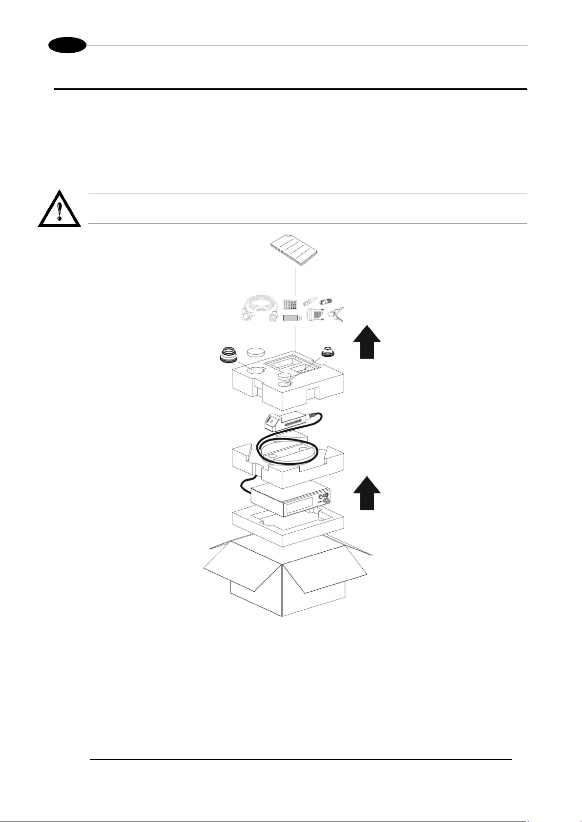
1.1 UNPACKING
When unpacking the marking system from the shipping carton you should:
• Remove the documentation from the top of the marking system
• Remove the accessories
• Carefully remove the marking system from the packaging using both hands
WARNING!
Be extremely careful to not damage the connection cable between Scan Head and Rack.
AREXTM 30W – 50W
Figure 2: Unpacking.
Before installing or operating the marking system, you should:
• Inspect the shipping container for damage
• Inspect the marking system for signs of damage
• Confirm that the shipping carton contains all items on the shipping inventory list including any
accessories
Retain all packaging m aterials until th e marking s ystem has been inspected f or completenes s and damage,
and you have checked the operating performance. If anything is missing or defective, see chapter 7 for
contact details.
Page 11
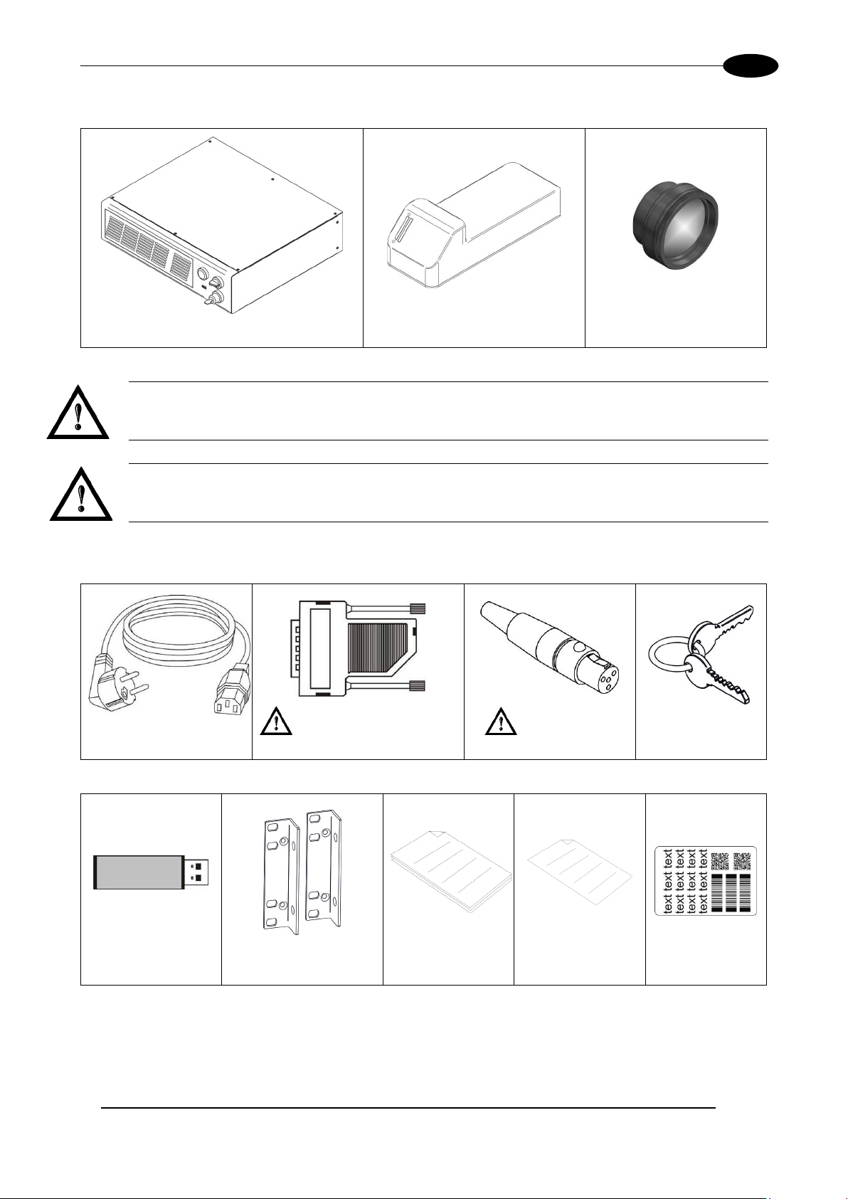
CONTENTS OF THE PACKAGING
11
Control Rack
Scan Head
F-Theta
1.2 MAIN HARDWARE
WARNING!
Rack and Scan Head are joined b y a conn ectio n cabl e 3 m et ers long, refer red a s Head Cable. Rack
and Scan Head are NOT separable.
WARNING!
To avoid damaging or break ing the optical fiber, never s ubject it to a bending radius bel ow the lim its
specified in the technical specification table.
1.3 CABLE AND ACCESSORIES
Power Supply cable Command Box Connector (*) Interlock connector (*) System Keys
USB flash drive Rack adapters Manuals Test Report Sample Test
* If this connector is used, the marking system works in DANGEROUS condition (MUTING DEVICE).
Page 12

AREXTM 30W – 50W
12
1.4 TRANSPORT
The m arking system can be easil y lifted up and moved by a single person thanks to its compact size and
reduced weight.
WARNING!
Rack and Scan Head are j o ine d b y a connec t ion cable 3 meters long. Rack and Scan Head are NOT
separable!
WARNING!
To avoid damaging or breaking the optical fiber, n ever subject it a bending rad ius below the limits
specified in the technical specification table.
Figure 3: Transport.
WARNING!
The ArexTM marking system is a delicate optical device, avoid damaging it with shock and vibrations.
WARNING!
Be extremely careful to not damage the connection cable between Scan Head and Rack.
1.5 ON MOISTURE CONDENSATION
If the marking s ystem is brought direct ly from a cold to a warm location, moisture may condens e inside or
outside the marking system. This moisture condensation may cause a malfunction of the marking system.
If moisture condensation occurs
Turn off the marking system and wait about 1 hour for the moisture to evaporate.
Note on moisture condensation
Moisture may condens e when you bring the m arking system from a cold place into a w arm place (or vice
versa) or when you use the marking system in a humid place as shown below.
How to avoid moisture condensation
When you bring the mark ing system from a cold place into a warm place, put it in a pl astic bag and seal it
tightly. Remove the bag when the air temperature inside the plastic bag has reached the ambient
temperature (after about 1 hour).
Page 13

CONTENTS OF THE PACKAGING
13
1.6 FIXING AND POSITIONING
The marking system must be positioned in a safely manner and the precautions listed below must be
followed:
Figure 4: Positioning rack.
Figure 5: Vertical positioning (need additional fixing).
WARNING!
DO NOT fix the marking system in manner not shown in figure.
Page 14

AREXTM 30W – 50W
14
The marking s ystem can be fitted inside a spec ial rack c abinet equipped with sp ecial support shou lders and
handles, available on request. The figure below shows the mounting points for mounting in rack (rack
handles available as accessory):
Figure 6: Fixing points on shrug rack (cabinet assembly).
NOTE:
In order to prevent mar king distortions, install a vibrom eter on the base of the piece to be mark ed
and check for the absence of vibrations during the marking process.
NOTE:
It is recommended to install the resonator on a micrometer positioning Z-axis system!
The Scan Head must be fixed to a suitable base (not supplied by Datalogic) using the four M5 threaded
holes and the two slotted seats:
Figure 7: Fixing points on Scan Head (vertical mount).
The Scan Head unit, just like the control rack, must be safely positioned and fixed to a stable surface,
vibration-free. The Scan Head can be fixed either vertically or horizontally. In order to prevent marking
distortions, avoid any vibration between Scan Head and piece to be marked.
WARNING!
It is very important to s ecure the laser system before you start m arking the piece since improper
securing or positioning may cause serious damage.
Do not secure the m arking system in a way other than the one described in the figure.
Page 15

CONTENTS OF THE PACKAGING
15
1.7 INSTALLATION ENVIRONMENT
The control rack must be instal led in a suitable environment in order t o allow proper air flow passage a nd
correct housing of the cables.
TM
is an air coole d marking system : an adequate air f low is necessar y to guarantee its c orrect cooling.
Arex
Installation must not slow or stop the flow of air cooling. Moreover, do not install a heat source near.
Clean air f ilter w hen it is d ir ty. If the air f ilter is dirt y, th e air -f lo w m ight b ec ome not sufficient to ensure correct
cooling and might stop marking operation. Clean or exchange air filter periodically.
Figure 8: Rack installation environme nt.
WARNING!
DO NOT place heavy objects on top of rack!
1.8 FUME / DUST EXTRACTOR
During marking proc ess, dust and/or gas may be produc ed. It is important to use ade quate fume extractor
and/or air filtration.
WARNING!
Marking PVC (or other plas tic material) can cause the release of chlorine gas which can be harmful
to the laser opera tor and to the las er system itself. Always use adequat e fum e extrac tor during PVC
and plastic marking.
Page 16

16
2 TECHNICAL SPECIFICATIONS
NOTE:
BEFORE INSTALLING AND USING THE LASER, RE AD CAREFULLY THE APPENDICES.
WARNING!
ArexTM is a CLASS 4 L ASER PRODUCT and it is the r esponsi bilit y of the O EM/s ystem integra tor t o
provide the safety completeness to be ready-to-use.
2.1 TECHNICAL CHARACTERISTICS
CONTROL RACK MECHANICAL CHARACTERISTICS
AREXTM 30W – 50W
Weight 16 Kg
Height 111 mm
Width 430 mm
Depth 370 mm
IP Rating IP21
SCAN HEAD MECHANICAL CHARACTERISTICS
Weight 3 Kg*
Height 90 mm*
Width 112 mm
Depth 300 mm
IP Rating IP54
* without F-Theta scan lens
NOTE:
Refer to Datalogic’s website for detailed drawings.
Page 17

TECHNICAL SPECIFICATIONS
17
Storage temperature
-10° to 60°C (14° to 140°F)
Package Drop Test
60 cm
30W
50W
Environmental temperature
5°C to 40°C (41° to 104°F)
5°C to 35°C (41° to 95°F)
Humidity
< 90% without condensation
Altitude
< 2000 m
Pollution Degree
2
Overvoltage Categor y
II
Input Voltage
100 to 240 V AC
100 to 240 V AC
Max Power
300W
330W
Modello 30W
50W
LASER SOURCE (specification @25°C)
Average Power W 30
50
Pulse energy (max)
mJ
1
Peak power (max)
kW
11
10
Central emission wavelength
nm
1060 - 1080
Repetition Rate
kHz
30 ÷ 200
50 ÷ 200
Laser aiming beam Class 2M ≤ 1mW @ 660nm
Cooling
Forced Air
Noise
dB(A)
< 70 at 1 meter
OTHER
HEAD CABLE
minimum bending radius
150 mm (fixed installation)
300 mm (mobile installation)
Marking head cable length
3 meters
Beam deflection
High speed galvanometer scanning system
MOF (Marking on the fly)
YES [constant speed or encoder]
Marking Control and Software
EMC embedded control and Lighter Suite
Communication
RS232, Ethernet (TCP/IP 10, 100 Mbit), digital I/O
STORAGE AND TRASPORTATION CONDITIONS
Shock and vibrations MIL 810E “CAT 1 Basic Transportation”
WARNING!
This product includes precision optical parts; avoid vibration and shocks: marking quality may deteriorate.
ENVIRONMENTAL OPERATING CONDITIONS
ELECTRICAL POWER SUPPLY
Input Current 3 to 1,25A max 3,3 to 1,4A max
PERFORMACE
Laser Type Class 4 Pulsed Fiber Laser
Laser Focus Beam Class 2 : 1 mW @ 635 nm
Marking Speed1 Up to 2000 mm/s -500 car/s
Line speed – Productivity2 Up to 75 m/min – 3 Pcs/s
1
May vary: measured with f= 160mm
2
Single line string, Roman-s font
Page 18

18
2.2 DESCRIPTION OF THE LASER MODULES
2.2.1 SCAN HEAD
A description of the main parts of the Scan Head unit is provided here below:
AREXTM 30W – 50W
Figure 9: Scan Head overview
1) Main connection Rack-Scan Head 3) Status LED bar
2) F-Theta Scan Lens 4) Focusing Beam output
Page 19

TECHNICAL SPECIFICATIONS
19
2.2.2 CONTROL RACK
The control rack is described here below in order to provide the right information for proper installation:
Figure 10: Control rack overview.
1) Status LED 9) I/O connector (Axes Control)
2) Enable selector 10) Main connection to Scan Head
3) Key selector 11) 3x USB connectors
4) USB connector 12) RS232 connector
5) Mains power supply connection 13) Interlock connector
6) LAN connector 14) Photocell connector
7) VGA connector 15) Encoder connector
8) Command Box connector (Laser Control) 16) Earth ground
Page 20

AREXTM 30W – 50W
20
F-Theta Scan Lens
ƒ = 160S
ƒ = 254S
Working Distance
mm
183 ± 5
280 ± 4
Fixing Distanc e
mm
197 ± 6
300 ± 5
Marking Area
mm2
85 x 85
100 x 100
F-Theta Scan Lens
ƒ = 160L
ƒ = 254L
ƒ = 330L
Working Distance
mm
176 ± 2
296 ± 5
388 ± 6
Fixing Distanc e
mm
212 ± 3
367 ± 6
471 ± 7
Marking Area
mm2
100 x 100
170 x 170
210 x 210
2.3 MARKING AREA SPECIFICATION
Datalogic provides a wide range of F-Theta sc an lenses to be attached to the scanning he ad to focus the
laser beam in flat Marking Field, in order to achieve high-resolution marking results.
These F-Theta scan lense s are available to best-match the object (i.e. : logo; string; 2D matr ix; etc.) to be
marked with custom er need, over the material processing, an d fit the standard Datalogic Scanning H ead;
further solutions about different models of lenses and scanning heads will be considered upon request.
The table below lists the standard F-Theta scan lenses currently availabl e:
F-Theta Scan Lens diameter: M39
F-Theta Scan Lens diameter: M85
NOTE:
Definition of Mark ing Area: square marking field within which power is > 95% respect to power in
center.
WARNING!
This product was d esigned to use only certain conf igurations of F-Theta lens and mark ing field. If
your needs are not satisfied by current available F-Theta lens configurations please contact
Datalogic for a solution. T he use of other F-Theta lenses or operation outs ide the specified m arking
field for a certain F-Theta l ens configuration can lea d to damage of F-Theta lens, scanning head or
laser source. Such damage is not covered by warranty!
WARNING!
For each F-Theta lens conf iguration Datalo gic recomm ends the use of c ertain adapter. This adapter
ensures that residual back ref lections cause d by F-T heta lens do not dam age optics of the scanni ng
head. The removal of such adapter or its incorrect use (for example inc omplete threading, use of
another F-Theta lens a dapter, etc .) can lead to damage of the F-Theta le ns, scannin g head or las er
source. Such damage is not covered by warranty!
Page 21
TECHNICAL SPECIFICATIONS
21
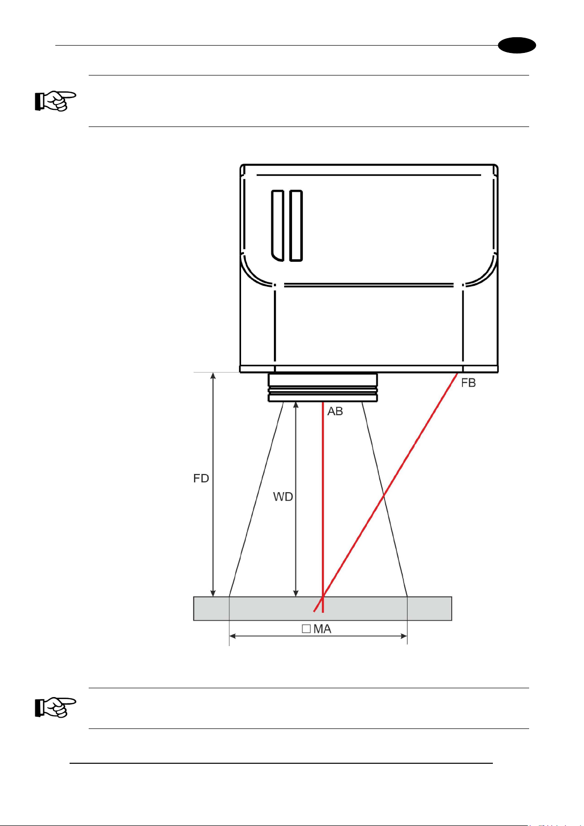
NOTE:
Working Distance is defined as the distance between the center of the marking area (defined
in the focal plane) and the last mechanical edge of the F-Theta Scan Lens. Refer to the
following figure.
WD: Working Distance
FD: Fixing Distance
MA: Marking Area
AB: Aiming beam
FB: Focusing beam
Figure 11: Marking area.
NOTE:
For systems equipped with standard Small F-Theta Scan Lens (M39) the focus condition is
obtained by matching the Aiming Beam with the Focusing beam.
Page 22

AREXTM 30W – 50W
22
2.4 CONNECTORS SPECIFICATIONS
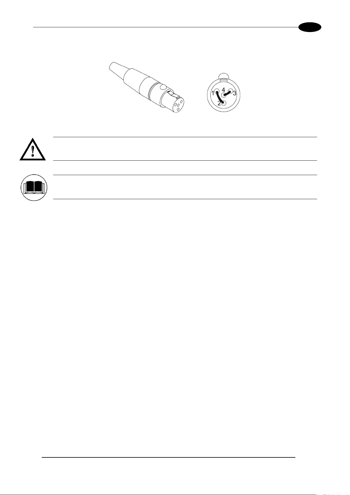
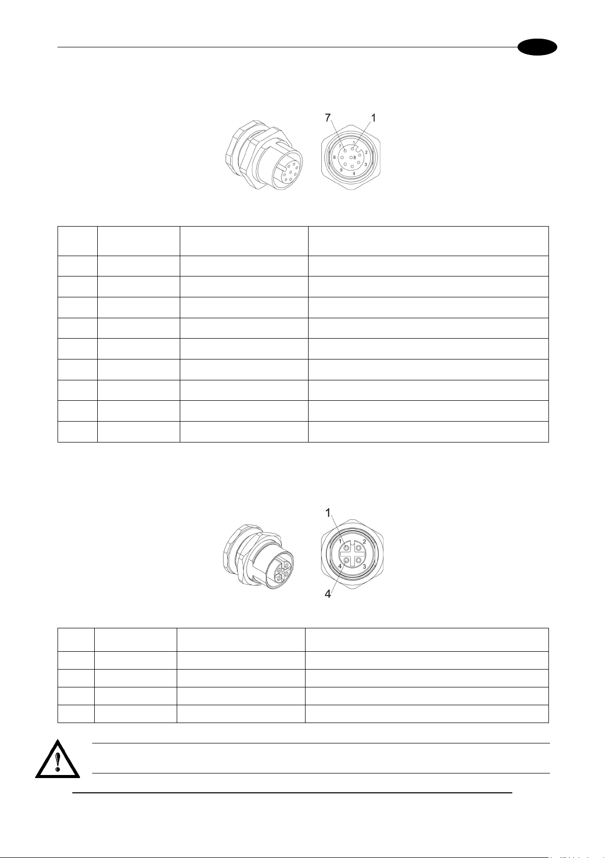
2.4.1 INTERLOCK CONNECTOR
Interlock disables the Class 4 laser sour ce inside the laser s ystem. Interlock internal circ uit is designed to
comply with the single fault conditio n.
PANEL CONNECTOR
Type SWITCHCRAFT TB Series male Tini Q-G (Mini XLR) panel mount connector, 4 positions.
Figure 12: Male panel plug cod. TB4M (front view).
NOTE:
See appendix D about the compliance to EN ISO 13849-1:2008.
PIN SIGNAL TYPE DESCRIPTION FUNCTIONAL DIAGRAM
1 VCC_INT_A OUTPUT
2 INTERLOCK_A INPUT
3 GND GND
4 INTERLOCK_B INPUT
24V DC reference for
INTERLOCK IN signal A
INTERLOCK IN signal A
Ground reference for
INTERLOCK IN signal B
INTERLOCK IN signal B
PIN 1- PIN 2 PIN 3- PIN 4 MARKING FUNCTIONALITY CONDITION
CONTACT OPEN CONTACT OPEN NOT POSSIBLE SAFE
CONTACT CLOSED CONTACT OPEN NOT POSSIBLE DANGEROUS
CONTACT OPEN CONTACT CLOSED NOT POSSIBLE DANGEROUS
CONTACT CLOSED CONTACT CLOSED POSSIBLE DANGEROUS
WARNING!
In order to NO T D AM AG E the i nterlock cir cuitry, we recomm ended using “dry circuit” ( zero voltage)
switches or relay circuitry.
Page 23
TECHNICAL SPECIFICATIONS
23
PLUG CONNECTOR
Connector type SWITCHCRAFT TA Series Tini Q-G (Mini XLR) female cable mount connectors, 4 positions.
Figure 13: Female cable mount connector cod. TA4FX (solder view).
WARNING!
If the interlock gold connec tor is used, the marking system is in DANGEROUS condition (MUTI NG
DEVICE).
NOTE:
To restore the marking system it is necessary to repeat the “Turning on sequenc e” without shutting
down the system. See chapter 4.1
for more details.
Page 24
24
Secondary external ENABLE signal (see par. 2.4.2.1)
- LOW level or disconnected: contact opened
Auxiliary 12V DC power supply available for drive input
Auxiliary 12V DC power supply available for drive input
Auxiliary 12V DC power supply available for drive input
This signal is used to start to the marking process when a
- HIGH level pulsed signal start the marking process
External KEY signal (see paragraph 2.4.2.2)
- LOW level or disconnected: contact opened
This signal is used to stop the marking process (see
- HIGH level pulsed signal stop the marking process
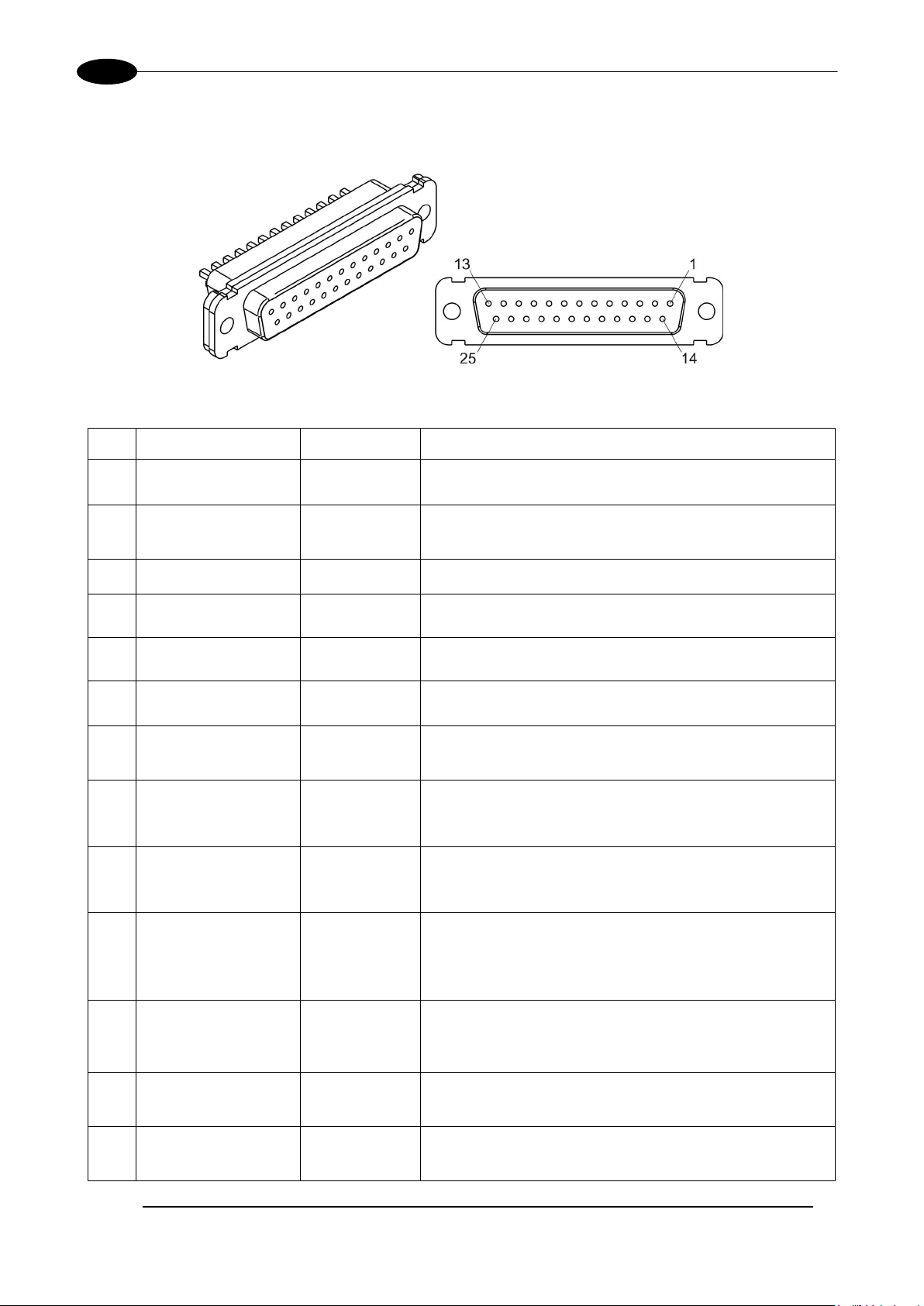
2.4.2 COMMAND BOX CONNECTOR (LASER CONTROL)
Panel socket Sub-D, 25 positions, female.
Figure 14: Female panel socket Sub-D 25 (front view).
PIN SIGNAL TYPE (***) DESCRIPTION
AREXTM 30W – 50W
1 12V_ENABLE_B
2 EXT_ENABLE_B Digital Input
3 RESERVED Digital Output DO NOT CONNECT
4 EXT_12V
5 EXT_12V
6 EXT_12V
7 12V_ENABLE_A
8 EXT_ENABLE_A Digital Input
9 BUSY (*) Digital Output
Output power
supply
Output power
supply
Output power
supply
Output power
supply
Output power
supply
12V DC power supply available for EXT_ENABLE_B
(max 250mA)
- HIGH level: contact closed
logical HIGH (max 250mA)
logical HIGH (max 250mA)
logical HIGH (max 250mA)
12V DC power supply available for EXT_ENABLE_A
(max 250mA)
Primary external ENABLE signal (see paragraph 2.4.2.1)
- HIGH level: contact closed;
- LOW level or disconnected: contact opened
This signal is used to know if the current spooler is
executing (marking in progress) (see paragraph 2.4.2.4)
- ON during marking process
CONNECTOR
10
PRESENCE
11 START MARKING (*) Digital Input
12 EXT_KEY Digital Input
13 STOP MARKING (*) Digital Input
Digital Input
This signal is used to check the presence of the
command box connector (see paragraph 2.6)
- HIGH level: normal operation;
- LOW level or disconnected: laser source faulty
document or a sequence is running in AUTO MODE (**)
or WORK MODE (**): (see paragraph
- HIGH level: contact closed;
paragraph 2.4.2.4)
2.4.2.4)
Page 25

TECHNICAL SPECIFICATIONS
25
14 RESERVED Digital Input DO NOT CONNECT
15 RESERVED Digital Input DO NOT CONNECT
16 RESERVED Digital Input DO NOT CONNECT
This signal is used to know if the marking process is
17 END Digital Output
18 POWER_ON Digital Output
19 GND Ground Ground reference
20 SYSTEM_ALARM Digital Output
21 GND Ground Ground reference
22 ENABLE_OUT Digital Output
finished: (see paragraph 2.4.2.4):
- ON at the end of marking process
This signal is used to know if the system is already
warmed up: (see paragraph 2.4.2.3)
- ON when the laser is in STAND_BY or READY state
This signal is used to know if the system is in booting up
state or in error state: (see paragraph 2.4.2.3)
- ON during BOOTING UP
- ON in case of system error
This signal is used to know if the system is ready to emit
laser radiation: (see paragraph 2.4.2.3)
- ON when the system is in READY state
This signal is used to know if a document, sequence or
script is loaded and ready to be executed:
- ON when a document or a sequence is running in
AUTO MODE (**) or WORK MODE (**) (SW_READY
23 SW_READY (*) Digital Output
COMPATIBILITY (**) = true)
- ON when a document or a sequence is running in
AUTO MODE (**) and laser in READY state
(SW_READY COMPATIBILITY (**) = false)
- ON when a script is running n AUTO MODE (**) and
“IoPort.setReady (true)” function is used
24 GND Ground Ground reference
25 GND Ground Ground reference
(*) refers to Lighter user’s manual “Setting I/O parameters” paragraph to set the signal properties
(**) refers to Lighter user’s manual
(***) refer to paragraph 2.5
NOTE:
Connection example in paragraph 2.6.
Page 26

AREXTM 30W – 50W
26
2.4.2.1 ENABLE SIGNAL’S SCHEME (COMMAND BOX CONNECTOR)
Figure 15: ENABLE signal’s scheme.
Page 27
TECHNICAL SPECIFICATIONS
27
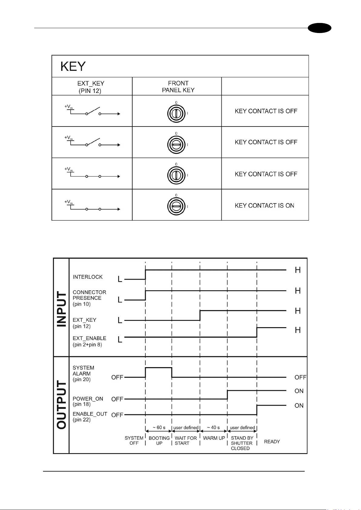
2.4.2.2 KEY SIGNAL’S SCHEME (COMMAND BOX CONNECTOR)
Figure 16: KEY signal’s scheme.
2.4.2.3 LASER CONTROL SIGNALS TIMING
Figure 17: Timing control signals.
Page 28

28
2.4.2.4 MARKING PROCESS SIGNALS TIMING
The following diagram illustrates the possible timings and settings of these signals:
AREXTM 30W – 50W
Figure 18: Timing signals
The time intervals in the diagram can all be programmed with a resolution of 1 ms
Start Time For setting the minimum acceptable time for the START_MARKING signal
T
1
Start Delay For delaying the start of marking process
T
2
Bus y Adva nc e BUSY signal corresponding to marking progress
T
3
T
Stop Time The minimum time for stop signal to stop the marking process
4
Busy Delay For delaying the Laser END signal with respect to laser emission
T
5
End Time For setting the Laser END activation time
T
6
(*) Refer to Lighter user’s manual “Setting I/O parameters” to set the signal’s properties.
(*).
Page 29

TECHNICAL SPECIFICATIONS
29
Generic input or X-Axis disable signal. When HIGH,
prior to activation
Generic input or Y-Axis disable signal. When HIGH,
prior to activation
Generic input or Z-Axis disable signal. When HIGH,
prior to activation
2.4.3 AXES CONNECTOR (I/O CONTROL)
Panel socket Sub-D, 25 positions, male.
Figure 19: Male panel socket Sub-D 25 (front view).
PIN SIGNAL TYPE (**) DESCRIPTION
1 EXT_12V
OUTPUT_0 (*) or
2
STEP_Y
OUTPUT_2 (*) or
3
STEP_Z
OUTPUT_4 (*) or
4
BRAKE X
OUTPUT_6 (*) or
5
BRAKE Y
OUTPUT_8 (*) or
6
BRAKE Z
INPUT_0 (*) or
7
ZERO X
INPUT_1 (*) or
8
ZERO Y
INPUT_2 (*) or
9
ZERO Z
INPUT_3 (*) or
10
DISABLE X
Output Power
supply
Digital Output
Digital Output
Digital Output
Digital Output
Digital Output
Digital Input
Digital Input
Digital Input
Digital Input
Auxiliary 12V DC power supply available for drive
input logical HIGH (max 250mA)
Generic output or Y-Axis drive step signal (Clock) for
axis control (**)
Generic output or Z-Axis drive step signal (Clock) for
axis control (**)
Generic output or X-Axis electromechanical brake
release signal. ON during drive motion
Generic output or Y-Axis electromechanical brake
release signal. ON during drive motion
Generic output or Z-Axis electromechanical brake
release signal. ON during drive motion
Generic input or X-Axis home sensor input. The home
search is stopped when this signal goes HIGH
Generic input or Y-Axis home sensor input. The home
search is stopped when this signal goes HIGH
Generic input or Z-Axis home sensor input. The home
search is stopped when this signal goes HIGH
the corresponding step signal remains in the status
INPUT_4 (*) or
11
DISABLE Y
INPUT_5 (*) or
12
DISABLE Z
13 GND Ground Ground reference
OUTPUT_12 (*) or
14
STEP R
OUTPUT_1 (*) or
15
STEP X
Digital Input
Digital Input
Digital Output
Digital Output
the corresponding step signal remains in the status
the corresponding step signal remains in the status
Generic output or R-Axis drive step signal (Clock) for
axis control
Generic output or X-Axis drive step signal (Clock) for
axis control
Page 30
AREXTM 30W – 50W
30
OUTPUT_3 (*) or
DIR Z
OUTPUT_5 (*) or
DIR Y
OUTPUT_7 (*) or
DIR X
INPUT_7 (*) or
ZERO R
Generic input or R-Axis home sensor input. The home
search is stopped when this signal goes HIGH
Generic input or R-Axis disable signal. When HIGH,
prior to activation
OUTPUT_9 (*) or
BRAKE R
Generic output or R-Axis electromechanical brake
release signal. ON during drive motion
OUTPUT_11 (*) or
DIR R
16
Digital Output Generic output or Z-Axis drive direction signal
17
18
19 INPUT 9 Digital Input Generic Input
20 INPUT 8 Digital Input Generic Input
21
INPUT_6 (*) or
22
DISABLE R
23
24
25 GND Ground Ground reference
(*) enable an axis cause that the correspondi ng signals will no longer be available as generic inputs/output. Refer to Lighter us er’s
manual, “Setting the X, Y, Z, and Rotor Axes parameters” to enable/disable Axes and set the Axes properties
(**) see paragraph 2.5
Digital Output Generic output or Y-Axis drive direction signal
Digital Output Generic output or X-Axis drive direction signal
Digital Input
Digital Input
Digital Output
Digital Output Generic output or R-Axis drive direction signal
the corresponding step signal remains in the status
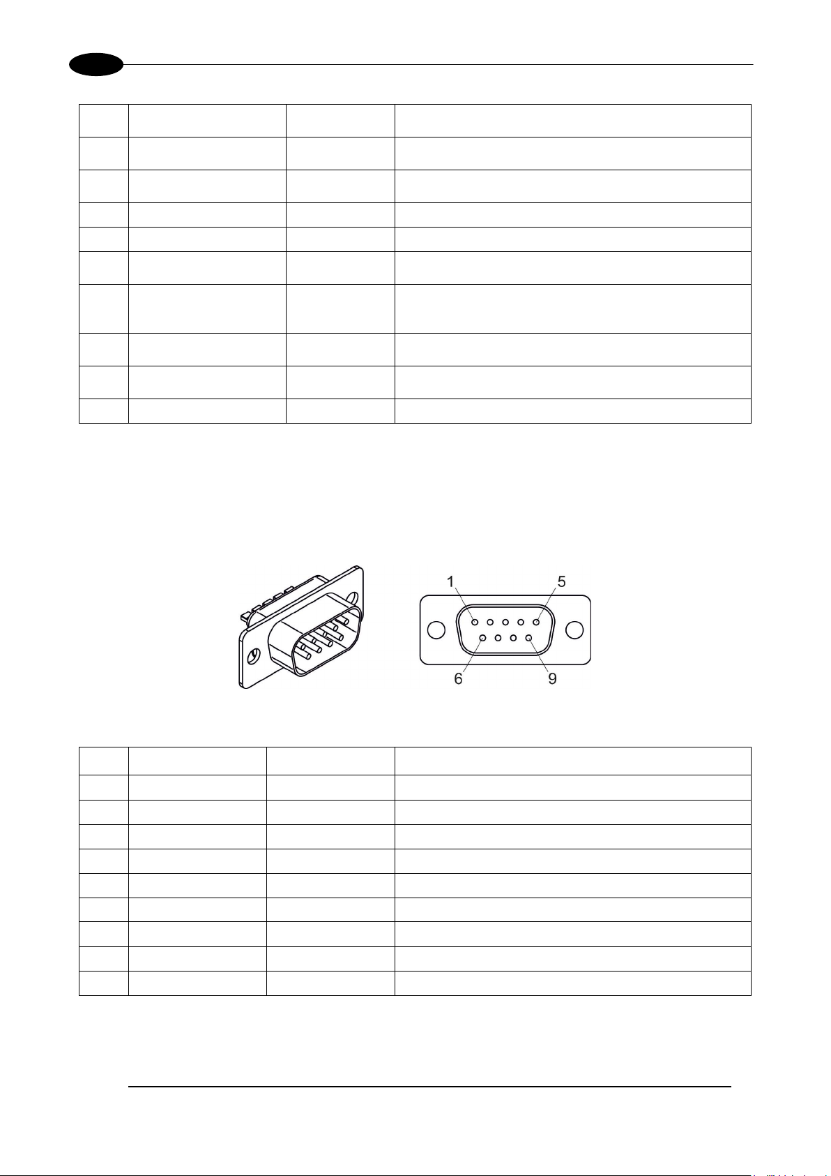
2.4.4 RS232 CONNECTO R (COM2)
Panel socket Sub-D, 9 positions, male.
Figure 20: Male panel socket Sub-D 9 (front view).
PIN SIGNAL TYPE DESCRIPTION
1 DCD Input Data Carrier Detect
2 RXD Input Receive Data
3 TXD Output Transmit Data
4 DTR Output Data Terminal Ready
5 GND Ground Ground reference
6 DSR Input Data Set Ready
7 RTS Output Request to Send
8 CTS Input Clear to Send
9 RI Input Ringing Indicator
Page 31
TECHNICAL SPECIFICATIONS
31
2.4.5 ENCODER CONNECTOR
Panel socket BINDER, M12, 8 positions fem ale, 763 series. Recomm ended encoder : Datalo gic ENC58-S10XXXX-M12 (ENC58-S10-5000-M12).
Figure 21: Female panel socket cod. 09-3482-87-08 (front view).
PIN SIGNAL TYPE DESCRIPTION
1 GND GND Ground signal
2 VCC POWER OUTPUT 12V DC power supply
3 ENC_A DIGITAL INPUT Encoder HTL A channel signal
4 GND GND Return signal for ENC_A
5 ENC_B DIGITAL INPUT Encoder HTL B channel signal
6 GND GND Return signal for ENC_B
7 NC NC NC
8 NC NC NC
BODY SHIELD SHIELD SHIELD
2.4.6 PHOTOCELL CONNECTOR
Panel socket BINDER, M 12, 4 positions fem ale, 763 series. Recomm ended photocell: Dat alogic S51-PA-5B01-PK; Datalogic S15-PA-5-B01-PK or equivalent.
Figure 22: Female panel socket cod. 09-3482-87-04 (front view).
PIN SIGNAL TYPE DESCRIPTION
1 VCC POWER OUTPUT 12V DC power supply
2 NC NC NC
3 GND GND Ground signal
4 PHOTOCELL DIGITAL INPUT PNP photocell signal
WARNING!
For EMC compliance a RICHCO RRC-16-9-28-M2-K5B (or equivalent) must be used.
Page 32
32
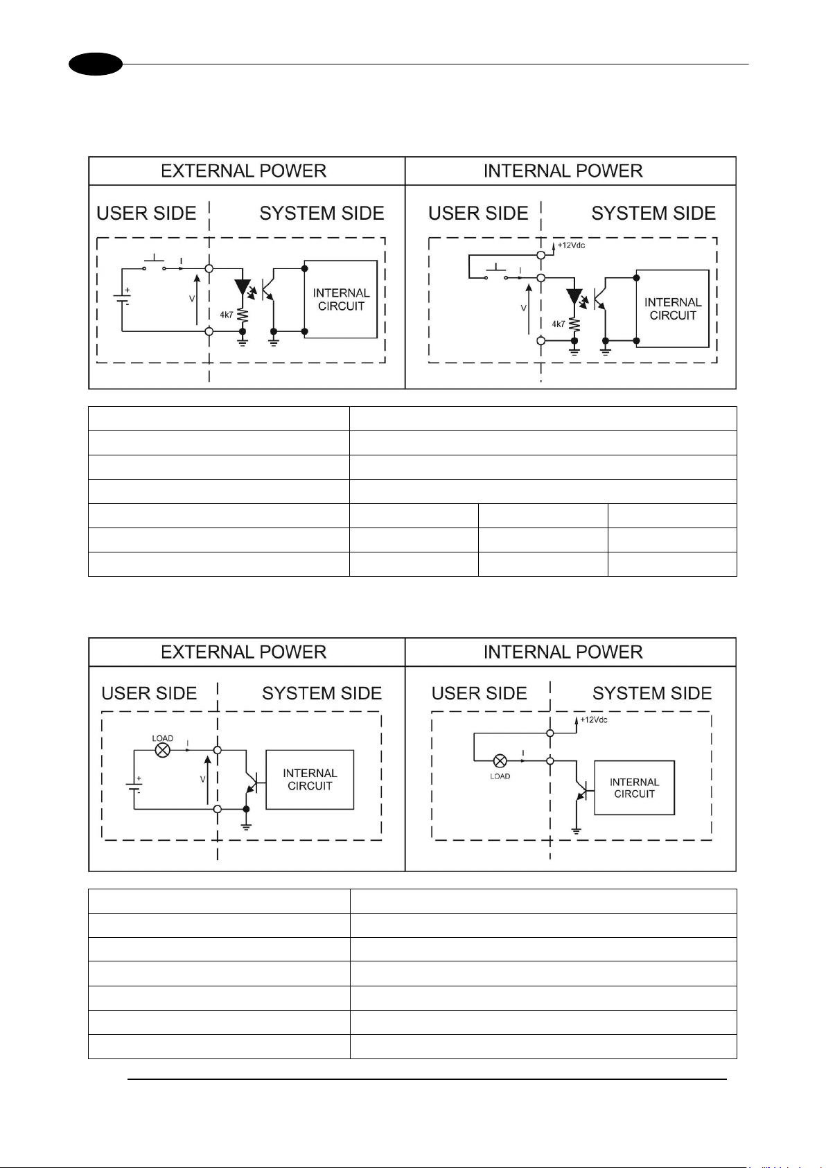
2.5 INPUT/OUTPUT SIGNAL SPECIFICATIONS
DIGITAL INPUT:
Type Optocoupler
V
24V DC
max
I
5mA @ 24V DC
max
Pulse Width ≥ 1ms (debounce)
AREXTM 30W – 50W
INPUT Logic LOW 0.0 V DC 0.0 V DC 2.0 V DC
INPUT Logic HIGH 5.0 V DC 12.0 V DC 24.0 V DC
MIN TYP MAX
DIGITAL OUTPUT:
Type Low side driver
V
24V DC
max
I
250mA
max
Vsaturation <0.5V DC
Leakage current < 5µA
OUTPUT State ON V ≤ 0.5 V DC; I ≤ 250mA
OUTPUT State OFF V ≤ 24 V DC; I ≤ 5µA
Page 33

TECHNICAL SPECIFICATIONS
33
2.6 CONNECTION EXAMPLE
Figure 23: Connection example.
NOTE:
See APP ENDIX C: AREX SAFETY CONSIDER ATION ACCORDING EN ISO 13849-1:2008 about
the compliance to EN ISO 13849-1:2008.
Page 34

AREXTM 30W – 50W
34
3 INST A LLATION A ND SET UP
3.1 CONNECTIONS
The marking system connecting is described here below. Follow the connecting operations as described.
WARNING!
Rack and Scan Head are j o ine d b y a connec t ion cable 3 meters long. Rac k and Scan Head are NOT
separable!
WARNING!
Connect the marking s ystem to other parts WITHOUT voltage in order to avoid risk s for the operat or
and for the laser source.
3.1.1 COMMAND BOX CONNECTOR CONNECTION
Figure 24: Connecting Command Box connector.
NOTE:
The Command Box con nector must alwa ys be inserted in ord er to use Enable and Key on the front
panel of the rack.
Page 35
INSTALLATION AND SET UP
35
3.1.2 INTERLOCK CONNECTOR CONNECTION
Figure 25: Connecting interlock connector.
WARNING!
If the interlock gold connector is used, the marking system is in DANGEROUS condition (MUTIN G
DEVICE).
NOTE:
The interlock connec tor must always be inserted in or d er to use the marking syste m. The absence of
such connector locks the marking system.
NOTE:
See APPENDIX C: AREX SAFETY CONSIDER ATION ACCORDING EN ISO 13849-1:2008 about
the compliance to EN ISO 13849-1:2008.
Page 36

36
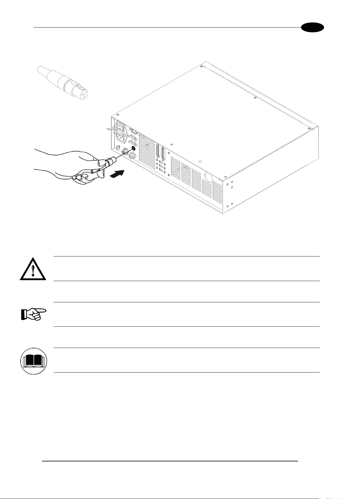
3.1.3 POWER SUPPLY CABLE CONNECTION
Connecting power supply cable.
AREXTM 30W – 50W
Figure 26: Connecting power supply cable.
NOTE:
Lock the plug with the retaining clamp to avoid accidental disconnection.
3.1.4 GROUND CONNECTION
To ensure high electrical noise immunity it is strongly recommended to connect the chassis to earth plant.
Figure 27: Ground connection.
Page 37

INSTALLATION AND SET UP
37
3.1.5 LOCAL MODE CONNECTION
To use the marking system in “Local Mode” it is necessary to install a mouse, keyboard and monitor.
Connect the monitor and input devices to marking system as shown below:
Figure 28: USB mouse connection.
Figure 29: USB keyboard connection.
Page 38
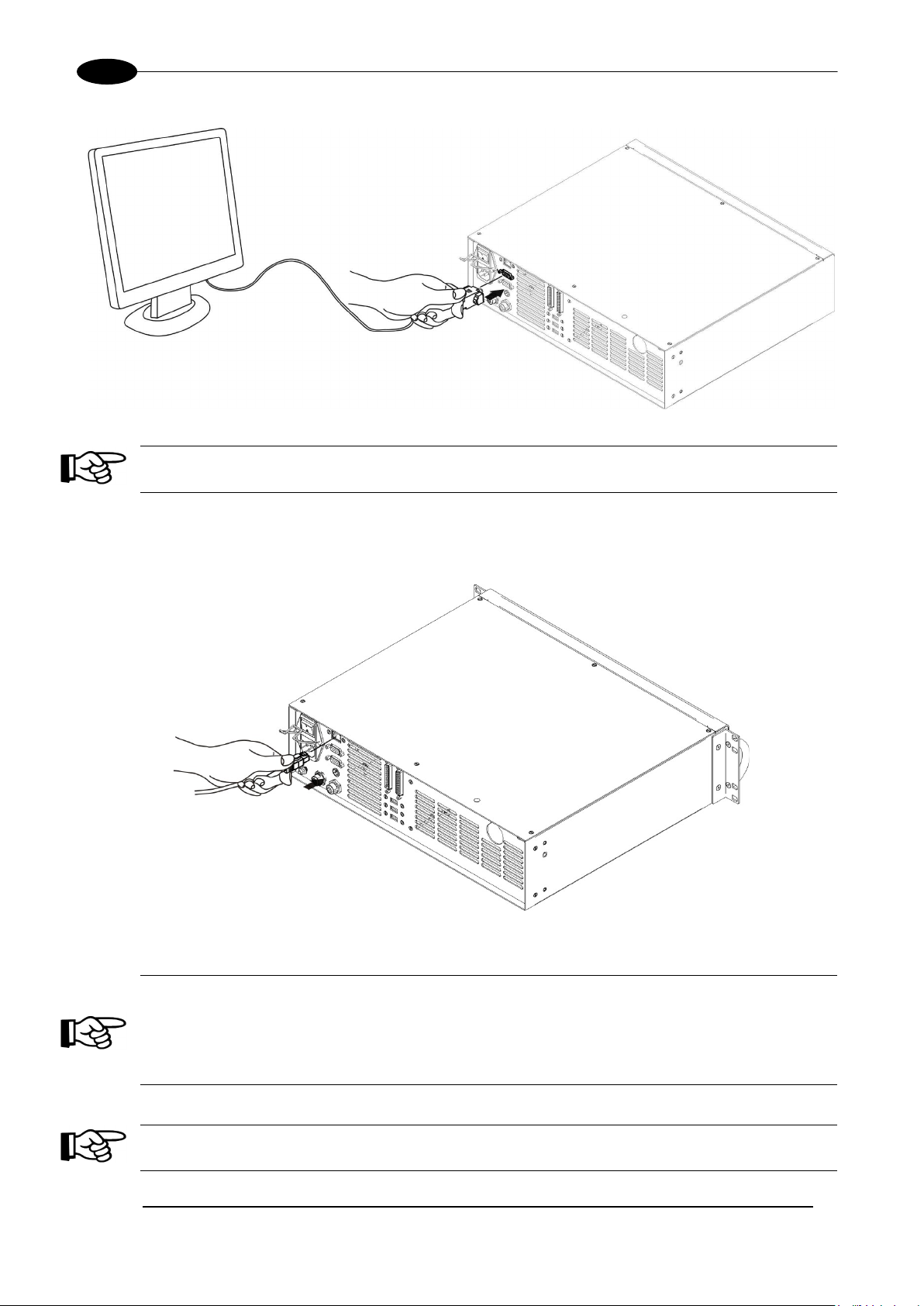
AREXTM 30W – 50W
38
Figure 30: VGA monitor connection.
NOTE:
Minimum resolution 800 x 600.
3.1.6 REMOTE MODE CONNECTION
To use the marking system in “Remote Control” mode it is necessary to connect a network cable:
Figure 31: RJ45 Ethernet connection.
NOTE:
The system LAN is configured by default with a fixed IP Address and Subnet Mask:
- Default IP address: 192.168.0.10
- Default Subnet Mask: 255.255. 255 .0
See chapter 5.2 in order to change LAN configuration.
NOTE:
Ethernet TCP/IP 10, 100 M bit.
Page 39

INSTALLATION AND SET UP
39
3.1.7 F-THETA LENS PROTECTION CAP REMOVAL
Remove the F-Theta Lens protection cap before marking operation.
Figure 32: F-Theta Lens protection cap removal.
WARNING!
Marking with the lens protection cap could result in damage to the lens.
Page 40
AREXTM 30W – 50W
40
4 USE AND OPERATION
4.1 TURNING ON SEQUENCE
Before turning on the marking system, be sure that the devices are connected as previously described.
Check presence of voltage power supply connection, interlock connector and Command Box connection.
Check that “KEY” and “ENABLE” comm ands on the rack front pane l are disabled (see Figure 15 and Figure
16).
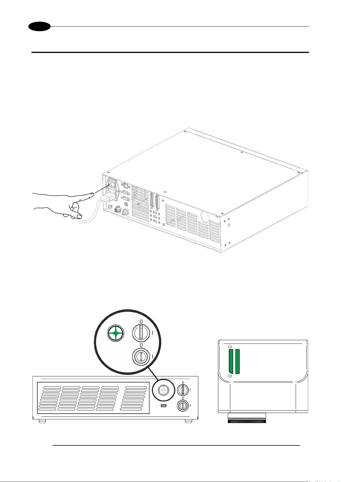
ST
: turn on the main switch in the back of the control rack:
1
Figure 33: Power on.
During booting-up, status LED on the rack front panel and the LED bar on Scan Head will be blinking green.
Wait the end of the booting-up. The status LED on the rack and the LED bar on the Scan Head will be
steady green.
Figure 34: Status LED display.
Page 41

USE AND OPERATION
41
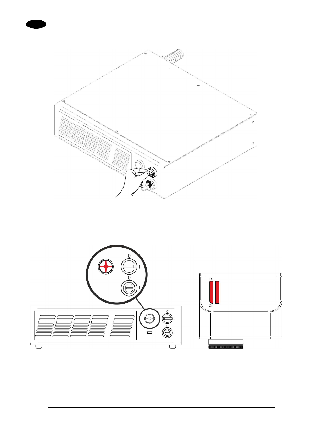
2ND: activate the command “KEY”, by rotating it clockwise:
Figure 35: Enable command KEY.
When the “KEY” comm and is enabled, t he status LED on the r ack and the status LED bar on the Scan Head
will be blinking orange for about 20 seconds (laser source warm-up).
Wait the end of the laser source war m-up. The s tatus LED on the rac k and the LED bar on the Scan Hea d
will be steady orange.
Figure 36: Status LED display.
Page 42
42
3RD: activate the “ENABLE” command by rotating it clockwise:
AREXTM 30W – 50W
Figure 37: Enable command ENABLE.
The marking system is rea d y to mark. The status LED on the rack and LED status bar o n the Scan Head will
turn red.
Figure 38: Status LED display.
Page 43

USE AND OPERATION
43
KEY
LOW
ENABLE
LOW
SYSTEM ALARM
ON
POWER ON
OFF
ENABLE OUT
OFF
KEY
LOW
ENABLE
LOW
SYSTEM ALARM
OFF
POWER ON
OFF
ENABLE OUT
OFF
KEY
HIGH
ENABLE
LOW
SYSTEM ALARM
OFF
POWER ON
OFF
ENABLE OUT
OFF
KEY
HIGH
ENABLE
LOW
SYSTEM ALARM
OFF
POWER ON
ON
ENABLE OUT
OFF
KEY
HIGH
ENABLE
HIGH
SYSTEM ALARM
OFF
POWER ON
ON
ENABLE OUT
ON
STATUS
STATUS LED
OUTPUT STATUS
(*)
SYSTEM ALARM
OFF
POWER_ON
OFF
ENABLE_OUT
OFF
SYSTEM ALARM
ON
POWER_ON
OFF
ENABLE_OUT
OFF
RESUME TABLE
STATUS STATUS LED INPUT STATUS
SYSTEM
BOOTING UP
WAIT FOR START STEADY GREEN
WARMING UP
STANDBY
SHUTTER CLOSED
READY STEADY RED
BLINKING GREEN (1Hz)
BLINKING ORANGE
(1Hz)
STEADY ORANGE
(*)
OUTPUT STATUS
(*)
WARNING
INVALID START SEQUENCE
BLINKING ORANGE (2Hz)
SYSTEM ERROR BLINKING RED (2Hz)
(*) See paragraph 2.4.2 for more information.
4.1.1 ADVICE ON USING THE SYSTEM
If the marking system is used in manua l mode you need t o connect Com mand Box connect or as described
before. In this way you are able to control the marking system directly on rack front panel.
If the marking system is used in autom atic mode it is recomm ended to enable pe rmanently Key and Enable
commands positioned on rack front panel and to use remote signals (EXT_KEY and EXT_ENABLE)
available on Comm and Box connector. T his part is supplied with the product an d you can connect exter nal
controls wiring connector contacts following pins description on paragraph 2.6.
Page 44

AREXTM 30W – 50W
44
Remote Active-X
4.2 LOCAL MODE OPERATIONS
The local mode (with monit or, k eyboard and m ouse co nnected) is optim al to ful ly benef it of the ALL-IN-ONE
Rack architecture characteristics.
SW Editor
SW Engine
+
Correction Matrix
=
Laser Control
Galvo Control
4.3 REMOTE MODE OPERATIONS
Keyboard, mouse and monitor are not necessary in this configuration.
LAN
SW Editor
Remote SW Engine
SW Engine
Correction Matrix
Laser Control
Galvo Control
Page 45

USE AND OPERATION
45
New IP ActiveX allows OEM integrators and end-users to create customized Applications and User
Interfaces via Ethernet.
Local or remote Activ eX control inter face is a vailable with the same c ommands to allow the us e of the sam e
application developed for both local and remote configurations.
LAN
Remote ActiveX
SW Engine
Correction Matrix
Laser Control
Galvo Control
Page 46

AREXTM 30W – 50W
46
Laser Editor is a software that allows to easily mark or engrave product identification
numeric serial n umbers, date
up that allows to oper ate on th e
select a saved docum ent, display limits using a r ed las er poi nter, w atc h th e marking
switch between Manua l/Auto mode (engra ving operations controlled b y operator or
Laser Engine Tray Icon
4.4 OPERATING IN LOCAL MODE
Connecting m onitor, mouse and keyboard to the s ystem (see paragraph 3.1.5) allo ws the oper ator to acc ess
the console which contains the instrum ents to operate with las er.
information such as 2 D matrix codes, barcodes, text, al phacodes, part numbers, graphics and logos in any production environment.
With Laser Editor you can:
o edit graphic layouts
o set laser parameters
o set marking system configuration
o control the integrated I/O module for axis management
o create automated procedures
o create programs using Lighter programming language
Laser Engine is an ap plicat ion aut om aticall y loaded at s tartmarking system. Laser Engine is present in the tray icon.
With Laser Engine you can:
o monitor the system status
o
preview and do marking tests
o
external signals)
Page 47

USE AND OPERATION
47
4.4.1 HOW TO CREATE AND EDIT YOUR FIRST GRAPHIC DOCUMENT
SIGNAL STATUS
EXT_KEY OFF
EXT_ENABLE_A OFF
EXT_ENABLE_B OFF
In “WAIT FOR START” status, double click on Laser Editor icon to start the layout editor application
Click on the document type selector and choose Layer:
Page 48

48
Click on the Text String icon in the Object toolbar to add a string object to the layer:
AREXTM 30W – 50W
Edit String properties such as value, font, style, etc. using the Properties browser:
Page 49

USE AND OPERATION
49
Edit Filling properties such as filling type, interline, etc. using the Properties browser:
Page 50

50
4.4.2 HOW TO TEST AND ENGRAVE YOUR DOCUMENT
SIGNAL STATUS
AREXTM 30W – 50W
EXT_KEY ON
EXT_ENABLE_A OFF
EXT_ENABLE_B OFF
In “STANDBY SHUTTER CLO SED” status , press L imits All butt on in the Laser Toolbar to a dj us t the obj ec t
position in the marking field:
Page 51

USE AND OPERATION
51
In “READY” status, adjust the Laser parameters using the Properties browser:
SIGNAL STATUS
EXT_KEY ON
EXT_ENABLE_A ON
EXT_ENABLE_B ON
Press Send Marking button in the La ser Toolbar to start the marking process:
Page 52

AREXTM 30W – 50W
52
4.4.3 HOW TO USE EXTERNAL SIGNALS TO ENGRAVE YOUR DOCUMENT
Automate the marking process allowing documents to be marked using external START_MARKING and
STOP_MARKING signals, that can be generated by PLC or other external devices.
Click on Save to Device button to save the layout in the device memory:
Click on Show Laser Engine button to display Laser Engine window:
AUTO/MANUAL Mode button allows switching between the two available working modes:
o Auto mode: the engraving operations are executed automatically using external signals.
o Manual mode: used for displaying the margins of the graphic objects to be marked and testing
layouts.
Page 53

USE AND OPERATION
53
Select the document from the list and click on To Auto Mode button:
The marking system is ready to mark document using external START_MARKING and STOP_MARKING
signals:
Page 54

AREXTM 30W – 50W
54
5 CUSTOMIZE THE SYSTEM’S SOFTWARE
5.1 CHANGE O.S. LANGUAGE AND KEYBOARD LAYOUT
The marking system allows you to personalize the op erating system changing t he language used in m enus
and dialogs, languages you can use to enter text and keyboard layout.
NOTE:
In order to perform this setting it is necessary to connect mouse, keyboard and monitor to the
marking system (see paragraph 3.1.5)
o Turn OFF and ON th e marking s ystem and wait the end of the boot ing-up (the status LED on th e
rack and on the scan head must be steady green)
o From the main screen click on Star t > Control Panel
.
o Select Change display language:
Page 55

CUSTOMIZE THE SYSTEM’S SOFTWARE
55
o In Keyboards and Languages select and choose the desired la ngu age.
o Select Change keyboards to change your keyboard or input language:
Page 56

56
o Select now input languages and press OK:
AREXTM 30W – 50W
o Close all the open s c reens and double clic k on the shortcut to save-data.bat icon in the Desk top
screen.
o A message advise you to restart or s hutdown the s ystem in order to perm anently save data. Press
OK:
o Shut down the system in order to save the new settings:
WARNING!
DO NOT turn OFF or UNPLUG the system while Windows® is shutting down.
o WAIT until system shuts down automatically (black screen)
o Power off the system to complete installation
Page 57

CUSTOMIZE THE SYSTEM’S SOFTWARE
57
5.2 CHANGE THE LAN CONFIGURATION AND IP ADDRESS
The system allows you to change the LAN configuration and IP address.
NOTE:
In order to perform this setting it is necessary to connect mouse, keyboard and monitor to the
marking system (see paragraph 3.1.5)
o Turn OFF and ON th e marking s ystem and wait the end of the boot ing-up (the status LED on the
rack and on the scan head must be steady green)
o From the main screen click on Star t > Control Panel
.
o Select View network status and task:
Page 58
AREXTM 30W – 50W
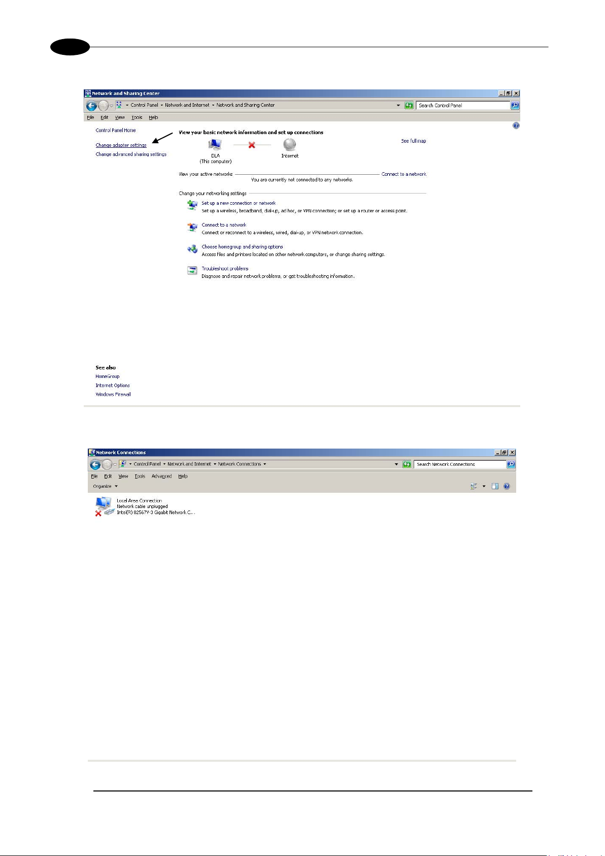
58
o In the Network and Sharing Center screen select Change adapter settings:
o In the Network Connections screen double click on Local Area Connection icon
Page 59

CUSTOMIZE THE SYSTEM’S SOFTWARE
59
o In the Local Area Connection Properties screen double click on Internet Protocol Version 4
(TCP/IPv4)
o In the Internet Protocol Version 4 (TCP/IPv4) Properties you can change the IP address and
configuration
o Close all the open s c reens and double clic k on the shortcut to save-data.bat icon in the Desktop
screen.
o A message advise you to restart or s hutdown the s ystem in order to perm anently save data. Press
OK:
o Shut down the system in order to save the new settings:
WARNING!
DO NOT turn OFF or UNPLUG the system while Windows® is shutting down.
o WAIT until system shuts down automatically (black screen)
o Power off the system to complete installation
Page 60
AREXTM 30W – 50W
60
5.3 CHANGE THE VIDEO SETTING
The system allows you to change the Video setting.
NOTE:
In order to perform this setting it is necessary to connect mouse, keyboard and monitor to the
marking system (see paragraph 3.1.5)
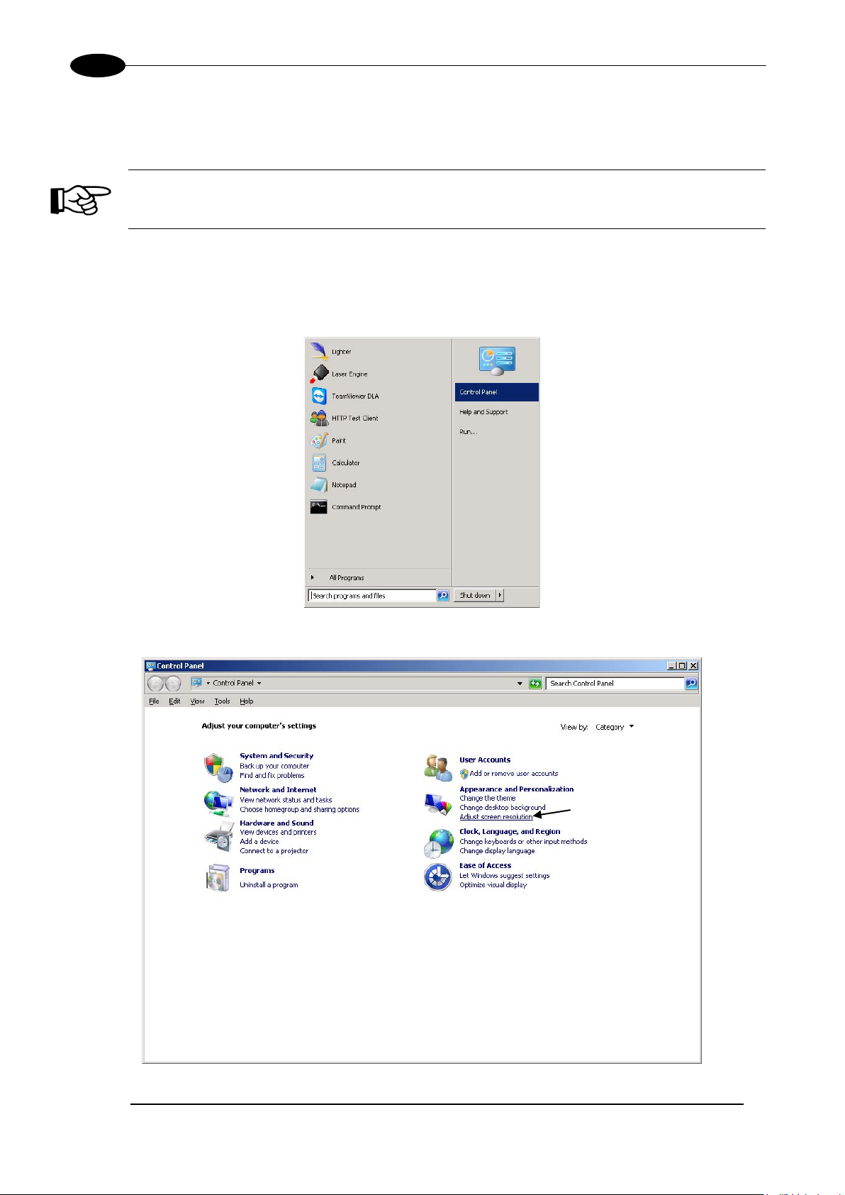
o Turn OFF and ON th e marking s ystem and wait the end of the boot ing-up (the status LED on the
rack and on the scan head must be steady green)
o From the main screen click on Star t > Control Panel
.
o Select Adjust screen resolution:
Page 61
CUSTOMIZE THE SYSTEM’S SOFTWARE
61
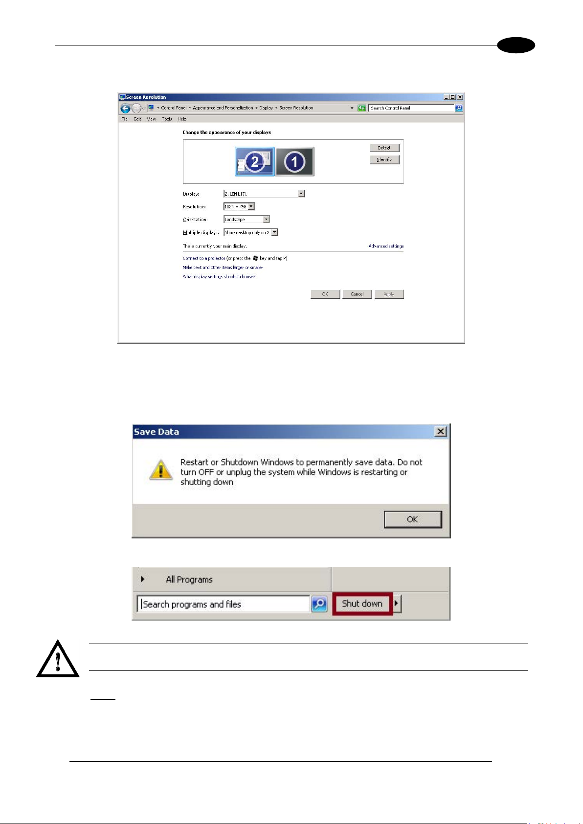
o In the Screen Resolution window select the desired Screen resolution and Color quality:
o Close all the open screens and double click on shortcut to save-data.bat icon in the Desktop
screen.
o A message advise you to restart or s hutdown the s ystem in order to perm anently save data. Press
OK:
o Shut down the system in order to save the new settings:
WARNING!
DO NOT turn OFF or UNPLUG the system while Windows® is shutting down.
o WAIT until system shuts down automatically (black screen)
o Power off the system to complete installation
Page 62

AREXTM 30W – 50W
62
5.4 REMOTE DESKTOP CONNECTION
To connect the marking system to a remote Windows based computer, follow these steps:
o Turn on marking system
o Make sure that both marking system and remote computer are connected to the LAN
o Click Start > All Programs > Accessories and then click Remote Desktop Connection
o Click Options
o In the Computer list, t ype the host name or the IP addr ess of the computer to which you want to
connect
o Type the user nam e, pass word, and domain ( if applic able) of an accoun t to which you have al lowed
remote access into the corresponding boxes, and then click Connect
Page 63
CUSTOMIZE THE SYSTEM’S SOFTWARE
63
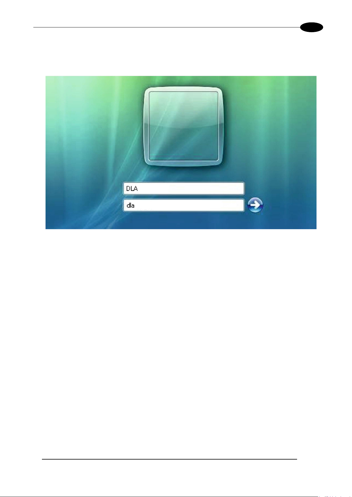
o In the Log On to Windows® dialog box that appear s, t ype the pass word of the a ccount with rem ote
access privileges into the Password box:
User name: DLA
Password: dla
o In the Log on to list, if applica ble, select the domain or remote c omputer that you want, and then
click OK
The remote desktop is displa yed in a wind ow on the d esk top. The rem ote computer is locked dur ing
this session
o To disconnect the sess ion, click the Close button in the session w indow, and then click OK when
you are prompted to disconnect the Windows
session.
Page 64

AREXTM 30W – 50W
64
Key selec tor
Selector switch for EXT_KEY control signal
Enable selector / ENABLE indicator
Selector switch for both EXT_ENABLE_A and EXT_ENABLE_B control sig nals with LED indicator
for ENABLE_OUT control signal
ALARM indicator
LED indicator for SYSTEM_ALARM control signal
START button / BUSY indicator
Pushbutton for START_MARKING control signal with LED indicator for BUSY control signal
STOP button / END indicator
Pushbutton for STOP_MARKING control signal with LED indicator for END control signal
READY indicator
External connector
Connection to Command Box connector
6 ACCESSORIES
The accessories listed here below are described for information purposes only, and are not necessarily
included in the pack aging. The minimum contents of the packaging include the main hardware, cables and
keys. For additional information, please refer to paragraph 1.2.
6.1 CONTROL BOX
Control and command device able to manage:
• Warmup the system
• Open the shutter and enable laser emission
• Start and Stop the marking process
• Show the marking process status
• Show the system error status
Figure 39: Control Box (Ordering no: 985330031).
1
2
3
4
5
6
LED indicator for SW_READY control signal
7
* Refer to Command Box connector (see paragraph 2.4.2) for detailed control signal’s description.
WARNING!
If the Control Box is used, the marking system works in DANGEROUS condition.
Page 65

ACCESSORIES
65
6.2 MARKING ON FLY KIT
The marking on fly kit is available on request. Kit includes: encoder, photocell, cables and plastic reflectors.
Figure 40: Kit MOF (Ordering no: 985330027).
6.3 RACK HANDLES
Handles for rack fastening are available on request.
Figure 41: Handles rack.
Page 66

AREXTM 30W – 50W
66
7 TECHNICAL SUPPORT
7.1 SEALS
The marking system has seals in some areas. The seals m us t not be br oken or removed for any reason. The
sealed parts ma y be open ed on ly and ex clus ivel y by Datalogic. Break age of these seals b y a c ustom er s hall
result in immediate cancellation of the warranty on the entire marking system.
WARNING!
If a customer breaks or remo ves th e seals p lac ed by th e m anufac turer on t he marking system the
warranty on the entire marking system will immediately become “null and void”
WARNING!
The manufacturer shall not be held liable for any non-conforming use of marking system of its
manufacture.
It is forbidden to operate the marking system before the machine it is intended for, has been
declared in conformance with statutory Directives
.
.
WARNING!
Access to the internal parts of the control rack is only permitted for authorized personnel, who have
been trained and instructed on the electrical risks.
Datalogic shall not be held liable for work on electrically charged parts by inadequately trained
personnel!
WARNING!
Access to the internal parts of the scan head is on ly permitted f or authorized personnel, who have
been trained and instructed on the optical risks!
Datalogic shall not be held liable for work on parts by inadequately trained personnel
!
Page 67

TECHNICAL SUPPORT
67
Every 3 months (according to the
7.2 MAINTENANCE
The ordinary maintenance program foresees only simple operations. Some operations consist in a mere
“check” of the operating condition.
The maintenance activiti es must be done in com pliance with the la w prescriptions r egarding the safet y rules
during the operations.
The following parts/functions have to be controlled:
MAINTENANCE PR O G RAM
COMPONENT OR FUNCTION TYPE OF OPERATION INTERVALS
Weekly: wipe gently with a dry cloth (or
F-Theta Scan Lens Check / Clean
soaked in high purity iso propyl alcohol) or
clean it with air blowing
Rack Air filters Clean / Replace
environment and frequency of use)
7.2.1 F-THETA SCAN LENS CLEANING PROCEDURE
WARNING!
Before cleaning the F-Theta scan lens, the marking system MUST be in set SAFE mode:
1- Disable EXT_ENABLE_A and EXT_ENABLE_B signals.
2- Disable INTERLOCK_A and INTERLOCK_B signals.
Figure 42: Cleaning F-Theta lens.
Page 68

68
7.2.2 AIR FILTER CLEANING PROCEDURE
AREXTM 30W – 50W
Figure 43: Removal of air filter.
WARNING!
In order to set the marking system in SAFE mode, disconnect AC power cable before starting
this operation!
1. Turn off key switch on controller unit
2. Disconnect AC power cable
3. Loosen screws of front panel and remove them
4. Remove filter
5. Clean filter with air blow or with neutral detergent and air-dr y i t
6. Reinstall the filter and protective cover
WARNING!
DO NOT install wet filter!
7. If filter cannot be cleaned, replace the filter
8. Suitable filters are available as spare parts
Page 69

TECHNICAL SUPPORT
69
7.3 PRODUCT SUPPORT AND CUSTOMER SE RV ICE
Warranty Information
Datalogic reser ves t he r i ght to c han ge t he inf or mation and specification c ont ai ner in this manual with out pr ior
notice.
Product Support
In the unlikely event that the marking system does not function normally and that it requires attention, contact
Datalogic for advice on further on-site fault diagnosis and/or module return.
If the marking s ystem is to be returned t o D atalog ic, e nsure th at al l rele vant r etur n doc um entation is in p lace
before shipment. Det ails of documentation requirem ents and copies can be obtained where requir ed from
Datalogic.
Pack the marking s ystem in the original packing a nd include all original acces sories and documentati on as
detailed in the original inventory. It is advised that the correct and original packaging is used to prevent
transit damage t o the marking s ystem. If part or all of the original pack aging is unavailable, pl ease contact
Datalogic for replacement items. Please take time to complete all return documentation. This can be
obtained from Datalogic and accurate details, diagnosis and comments in the documentation can help
reduce turnaround time for module repair at Datalogic.
Customer Service Contacts
Product Support
support-dla-lasermarking@datalogic.com
Tel: +39 051-3147011
Customer Services
service-dla-lasermarking@datalogic.com
Tel: +39 0331-918001
Company Web Site
www.datalogic.com
For further contact information see the Contact Us link at www.datalogic.com or contact your local distributor.
Page 70

70
APPENDIX A: LABEL
LABEL DESCRIPTION
Identification label 30W
Identification label 50W
Warning logotype (Laser)
Laser Label (Scan Head)3
Aperture Label
Label for non-interlock protective housing
Caution, possibility of electric shock
Generic Warning
USB plug
MAC Address
0 - I KEY/ENABLE Positions
COMMAND BOX Command Box connector
AXES (I/O) Control Axes connector
INTERLOCK Interlock connector
LAN LAN connector
RS232 RS232 connector
VGA VGA connector
PHOT Photocell connector
ENC Encoder connector
2xT5A Fuses
3
Maximum output of laser radiation as per definition 3.55 of IEC60825-1 considering single fault conditions.
Page 71

71
POSITIONING OF EXTERNAL LABELS
Positioning of labels on the control rack:
Figure 44: External labels rack location.
Positioning of labels on the Scan Head:
Figure 45: External labels Scan Head location.
Page 72

72
APPENDIX B: STANDARDS
LASER STANDARDS
The marking system is designed to comply with the applicable sections of these laser standards:
EU : EN60825-1
USA : 21 CFR 1040.10
The marking system is classified as Class 4 Laser Product.
Datalogic, as m anufacturer of marking system, provides a laser which is NOT intended for im mediate use,
but it must be connec ted, by ot hers, t o other de vices whic h have the final a im of c reating a laser proc essing
system.
The final system manufacturer MUST ensure the safety of the laser processing machine according to its
standards including the ris k-analysis, implementation of safety measures, certification and tes ting of safety
measures and the production of adequate information for use of the machine.
Datalogic is available f or providing to the s ystem integrator/O EM all the inform ation in its possessio n to help
in complying with applicable standards.
CE COMPLIANCE
CE marking states the compliance of the product with essential requirements listed in the applicable
European directive.
Since the directives and applicable standards are subject to continuous updates, and since Datalogic
promptly adopts these updates, therefore the EU declaration of conformity is a living document.
The EU declaration of conformity is available for competent authorities and customers by Datalogic
commercial reference contacts.
Since 20th April 2016 the m ain European directives applicable to Datalog ic products require to include an
adequate analysis and ass essm ent of the risk(s ). This evaluat ion was c arried out in relatio n to the appl icab le
points of the standards listed in the Declaration of Conformity.
Datalogic products are mainly designed for integration purposes, into more complex systems. For this reason
it is under the responsibility of the system integrator to do a new risk assessment regarding the final
installation.
WARNING!
This is a Class A produc t. In a Class B environment this product m ay cause radio interference in
which case the user may be required to take adequate measures.
FCC COMPLIANCE
Modifications or changes to this marking system with out the expressed written approval of Datalogic coul d
void the authority to use the system.
This system complies with PART 15 of the FCC Rules. Operation is subject to t he following t wo conditions:
(1) This system may not cause harmful interference, and (2) this system must accept any interference
received, including interference which may cause undesired operation.
This marking system has been tested and found to comply with the limits for a Class A digital device,
pursuant to part 15 of the F CC Rules. These limits are designed to provide r easonable protection against
harmful interference when the system is operated in a commercial environment. This marking system
generates, uses, an d can radiate radio frequenc y energy and, if not install ed and used in accordance with
the instruction manual, may cause harmful interf erence to radio comm unications. Operation of this marking
system in a residentia l area is likely to cause harm ful interference in whic h case the user will be required t o
correct the interference at his own expense.
Page 73

73
APPENDIX C: AREXTM SAFETY CONSIDERATION ACCORDING EN ISO 13849-1:2008
The interlock connector located to t he rear of the ArexTM laser m arking system is the interface of the internal
safety-related parts of control system (SRP/CS).
With appropriate use of safety external components AND the application of the suggested
maintenance, the SRP/CS of the machine that uses Arex
Category 3, PL c.
Interlock is used t o put the marking system in a saf e operating mode because the action is to rem ove the
power to the laser source.
According to Categ ory 3, Arex
INTERLOCK B. For a normal operation INTERLOCK A signal must be short circuited to its reference
VCC_INT_A and INTERLOCK B signal must be short circuited to its reference GND.
The opening of at le ast o ne c hannel causes the p ower rem oval fr om the interna l laser sourc e. T he respo nse
time from full laser emission to zero emission is < 5ms.
TM
as components will result in Safety
TM
interlock is made by two separate c han nels , referred as INTERLOC K A and
The connector’s pin-out description is:
PIN SIGNAL TYPE DESCRIPTION
1 VCC_INT_A OUTPUT
2 INTERLOCK_A INPUT
3 GND GND
4 INTERLOCK_B INPUT
24V DC reference for INTERLOCK signal A
INTERLOCK signal A
Ground reference for INTERLOCK signal B
INTERLOCK signal B
Page 74
74
YES
NO
NO
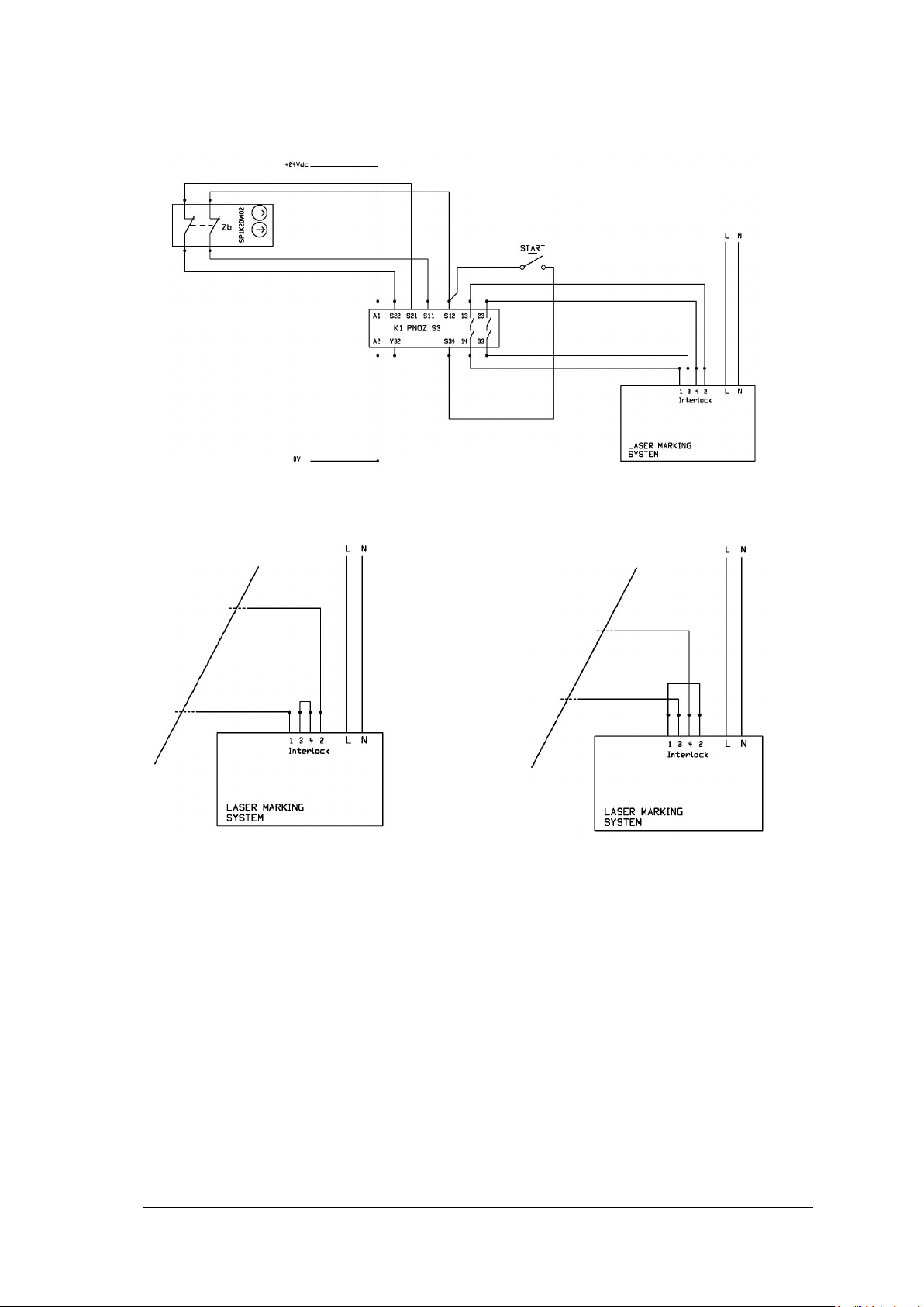
The following diagram is a n example of the c orrect co nnection between th e inter lock connector and a safet y
relay:
The minimum requirement for safety relay is Cat.3 PL d.
Do not by-pass one of the two interlock channel:
Maintenance:
The functionality of each interlock channel should be checked every 100 working hours following this
procedure:
1 – set the system in laser “READY” status
2 – open only INTERLOCK_A channel
3 – check of INTERLOCK_A channel is OK if the system goes into “interlock error status” and t he noise
produced by the fans is lower
4 – do the same for INTERLOCK_B channel
5 – final check is OK if both interlock channels are O K. If Final Ch eck is not OK , and the ro ot cause is due
to Arex
issue, please contact your supplier of the system.
TM
, the unit should be return ed to the manufactur er or authorized repair center. To manage this
General information:
Safety MUST be a part of our conscience.
The safety devices fulfill their safety function only if they are correctly installed, in accordance with the
Standards in force.
If you are not certain to have the expertise necessary to install the marking system in the correct way,
Datalogic Technical Support is at your disposal to carry out the installation.
Page 75

75
SAFETY FUNCTIONS OF AREXTM
ArexTM provides inputs and actuators to implement the following safety functions:
- SF.1 ENABLE (e.g. no IR laser output if "EXT_ENABLE_A" or "EXT_ENABLE_B" are disabled,
where "disabled" means contacts open)
- SF.2 INTERLOCK (e.g. no IR laser output if "INTERLOCK_A" or "INTERLOCK_B" are disabled,
where "disabled" means contacts open)
These functions has been evaluated according to UNI EN ISO 13849-1. The results are:
- SF.1:
- Category: B
- MTTFd <10 years
- DC: none according category
- SF.2:
- Category: 3
- MTTFd = 113 years (dop=365days, hop=24h, Tcycle=1800s)
- DC: because Arex
the process. The estim ate for DC is 0% t o 99% depen ding on the applicat ion. Thi s measure alone
is not sufficient for the PL "e". If it is executed a test every 100 working hours, then DC=60%.
- Response time: 5ms
TM
doesn't provide f eedbacks, a measure of fault detection must be included in
Page 76

76
APPENDIX D: NOTE ABOUT LASER
LASER SAFETY
The following inform ation is provided in compliance with regulat ions set by International Authorities, and it
refers to proper use of the marking system.
WARNING!
It is crucial that you protect yourself against beams of reflected or direct light as they cause
permanent damage to your skin
.
WARNING!
Staring directly at a laser beam may cause irreversible damage to your eyes.
WARNING!
Wear safety goggles while using the marking system!
NOTE:
BEFORE INSTALLING AND USING THE LASER, READ CAREFULLY THE APPENDIX
CONCERNING LASER SAFETY.
Page 77
77
LASER RADIATION
Laser radiation is an electromagnetic emission with a micrometric wa velength which ranges from the long
infrared (CO
(excimer laser).
It should be considered non-Ionizing Radiation. In Arex
stimulated by “optical pum ping” generat ed by a Diode Las er. The continuous ref lection of Photons , between
a front mirror and rear mirror, c reates a positive reaction so that their number continues to incre ase, until
reaching the concentr at ion nec ess ary to produce a beam which projects f rom t he semi-reflecting front mirror.
The radiation (whic h we can imagine as a “Beam of in visible light”) is then Collimated a nd Focalized with
Lenses at a point where the intensity becomes high enough to be able to react with various materials
producing an alteration in them due to thermal effect.
The radiation of Arex
the natural defense pro vided b y pupil ref lex! Added to t his is the f act that it is generally very intense , with t he
result that it can be very harmful to the eye and present vision problems.
To prevent permanent damage to vision, a few precautions must be taken.
All individuals who m ay be exposed to da ngero us l evels of laser rad iation , m ust k now that th e laser is ac tive
and wear protective goggles if necessary.
Las er), close infrared (Yd fiber , Nd:YAG, Nd:YVO4), visible (He:Ne or Argon) and ultr aviolet
2
TM
marking system, the emission of a light is
TM
marking system is invisible and the Eye receives it alm os t in its e nt ir et y wi tho ut us ing
WARNING!
Directly viewing a las er bea m can cause irreversible damage to vision.
Due to its high power, the laser integrated in the Datalogic system provokes reflected laser light from flat
surfaces. Reflected light is potentially dangerous for the eyes and skin. Electromagnetic emission with a
micrometric wavelength is placed in long infrared, and is therefore invisible, thus it is not clear where
reflected beams are aimed.
WARNING!
It is indispensable to protect yourself from reflected light beams, because they can be
sufficiently intense to create permanent injury to the eyes or skin
In addition to possible injur y to the e yes or sk in, direc t laser em ission can c ause flam m able materials to burn
like organic solvents (alcohol, acetone) or gasoline and cause fabric and clothing to burn.
.
WARNING!
This marking system is classified as Class 4. Class 4 includes lasers which can produce r isks, not
only from direct or reflected radiation, but also fr om scattered radiat ion! T he laser sour ces m ay be
a significant risk for the skin and risk of burning flammable materials
.
Page 78
78
ABSORPTION OF LASER RADIATION
Human skin absorbs electromagnetic radiation in different ways depending on the wave length of the
radiation. Both the e ye and skin have a “predisposition” f or accepting certain wave lengths, and are more
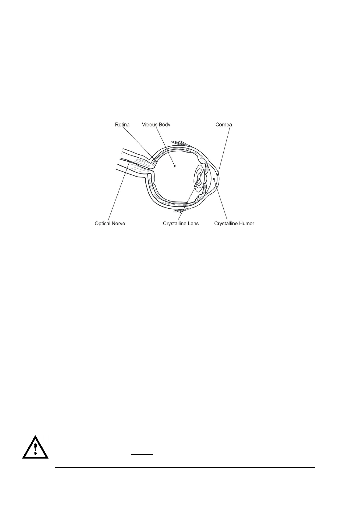
unresponsive to absorbin g others. In the spec ific case of the E ye, the Cornea and Cr ystalline lens let al l the
wave lengths from 400 to 1 400 nm pass and reach t he Retin a, even with vari ous atte nuations. T hey inc lude
the range from visible light to IRA infrared. T hus Arex
this range and leads to direct Retina exposure!
In terms of the Skin, the “biological window” has different absorption percentages but is not dissimilar in
terms of wave length. The maximum exposure values for Skin are much different compared to those
tolerated by the Eye.
TM
laser radiation (1070 nm wavelength) is included i n
Figure 46: Eyeball section.
In terms of the damage m echanism that absorbed ra diation can cause, it also depends on the wave length.
Short lengths (ultraviolet: UV-C 18 0-280nm; UV-B 280-315 nm , UV-A 315-400 nm) generall y cause photochemical effects:
• cataract, or opacification of the crystalline lens
• melanic coloring, or reddening of the skin
Greater wavelengths (inf rared: I R-A 780-1 400 nm ; I R-B 1400 3000 nm; IR-C 300 0-10
thermal effects:
• detachment or photocoagulation of the retina
• burning of the skin
The degree of injury obviously depends on the amount of absorbed radiation and the instantaneous
power of the radiation source.
E6
nm) gener all y cause
CLASSIFICATION AND DANGER LEVEL
Regulations have esta blished different classes of Las er danger based on the ability to injur e people, from
Laser Class 1 (basically safe in all conditions) to Laser Class 4 dangerous in various conditions .
Lasers which can produce risks, not only for direct or reflected radiation, but also for scattered radiation
belong to Class 4. These Laser sources can also have a significant risk for the Skin and fire risk for
flammable material. For these reasons, the User m ust put into effect all measures aim ed at containing the
radiation to make sur e that it is term inated at the end of its useful path. The oper ator mus t also be inform ed
of the risks from exposure to Laser radiation and mus t wear specific I.P.D. (individual pr otection devices)
including goggles that protect against radiation and are certified as suitable for this use.
WARNING!
The ArexTM marking system contains a Class 4 invisible laser source.
Page 79

79
RADIATION VIEWING CONDITIONS
The Laser output by the Sc an Head is to be considered as a hig hly collimated and intense m onochromatic
light source. Due to these char acteristics it can be seen as a “point source” of high lum inosity. This means
that its image is then focal ized on the Retina in a v ery small spot with a dang erously high power dens ity! If
the beam becom es divergent and scatters to a no n-reflecting screen, then there is an “extended visi on” of
the image, with a decisivel y less dangerous power de nsity. So there are different types of radiation viewing
based on the access to the radiation and consequently different degrees of dangerousness.
DIRECT VIEWING OF THE LASER BEAM
This type of viewing is t he most dangerous and can occur at the outlet of the laser aperture after ha ving
removed the lens. It is to be avoided at all costs ! No protective goggles repre sent a valid means against
direct viewing of the beam.
DIRECT VIEWING OF THE BEAM AFTER MIRROR REFLECTION
This may occur by directing the beam on a reflecting surface.
Viewing of a mirror reflected beam from a flat surface is very dangerous and equal to direct viewing.
DIRECT VIEWING OF THE BEAM OUTPUT BY AN OPTICAL FIBER
This happens if an Optical Fiber d isconnec ts f rom t he Scan Head. Viewi ng of the beam is danger ous up to a
significant distance. Filters and Goggles do not ensure safety.
DIRECT VIEWING OF THE BEAM AFTER FOCUSING
This occurs if the Laser beam is not extinguished with an opportun e absorber at the end of its us eful path.
Looking at the beam is dangerous up to a co nsiderable distance. Filters and goggl es can ensure safet y for
brief exposure, as long as they are the right size and certified.
SCATTERED VIEWING OF THE BEAM AFTER FOCUSING
This is the most frequent vi ewing, but opportun e Filters and Goggles can ensure safet y, even for prolonged
exposure.
The Nominal Ocular Hazard Distance N.O.H.D. for Arex
WARNING!
Always use goggles with conformity certificate.
Remember that no goggles can provide prolonged protection from direct or mirror-reflected
radiation
!
TM
is showed in the next paragraph.
Page 80

80
N.O.H.D. DETERMINATION AND O.D. OF PROTECTION GOGGLES
In order to determinate the characteristics of the protection goggles, it is essential to determine the
characteristics of the radiation, knowing its optical path, the dimensions of the beam and its divergence.
It is very import ant to know the real divergence of the beam in output from the focali zation scan lens (FTheta).
With all these optical data it is possible to calculate the Nominal Ocu lar Ha zard Distance (N.O.H.D.) and the
optical density (O.D.) requested to the protection filters of the laser radiation.
Calculations have been done following the CEI EN 60825-1 (2014) Normative regarding nominal
distance and optical risk in the worst condition and in case of accident exposure of 10 seconds for
direct radiation and 100 seconds for diffused radiation.
Wavelength RIF
Laser Type Q-Switched fiber laser
Observation type Direct radiation
Pulse energy
Pulse duration 100 ns
Beam Diameter at F-Theta lens exit DL ~ 6.0 mm
Beam divergence on the lens
Focal of the F-Theta lens F 160 mm
θ
2
1070 nm (± 10 nm)
1120 nm (Raman emission)
1 mJ @ 30 kHz for AREX 30W
1 mJ @ 50 kHz for AREX 50W
0.8 mrad
Real divergence after the lens
Exposure time 10 s
Max beam scanning angle ± 20° each axis
θ
3
31,2 mrad
Page 81

81
N.O.H.D.
(Nominal Ocular Hazard Distance)
ACCIDENTAL CONDITION OF VISION OF THE DIRECT REFLECTED RADIATION
Assuming a direct exposure of 10 seconds at a nominal distanc e of 0,5 m (worst c ase considered), with F Theta Scan Lens 160 mm model installed, it is poss ible to calculate the suitable optical density (O.D.) for
safety goggles.
The O.D. (Optical Density) in last column assures the reduction of laser radiation below max acceptable
exposure.
O.D.= log (H/EMP) where EMP is the Maximum Permissible Exposure and H is the radiant exposure.
Source
ArexTM Marker 30W 31,6 m > 4.19
ArexTM Marker 50W 40,8 m > 4.41
SCALE INDEX OF THE PROTECTION GOGGLES FILTER
The scale index L of the filters indicates the sta bility to the radiation, that m eans the ability of the filter to
maintain its characteristics unchanged.
This stability is certified by the producer according to the UNI EN 207.
It is then necessar y to ver if y th at t he s cal e ind ex of the ado pt ed f ilter is stab le f or t his per iod an d f or es een an
adequate over dimensioned in order to make sure that it could last longer than the accidental exposure
period.
In case of exposure at 0,5 m for 10 seconds, the suggested optical density for safety goggles is CLASS L4.
O.D. (Optical Density)
Page 82

82
EYES AND SKIN RISKS
If exposed to intense Laser radiation, even of a short duration, or a less intense but lon ger lasting durat ion,
both the Cornea and the Retina can burn and be damaged irreparably forever. This consequence is
completely realistic in the event of direct viewing of a Class 4 Laser beam.
If subject to direct focalized radiation, even the skin can burn.
In addition, it is necessary to bear in mind that a collateral ultraviolet radiation may exist with the main
radiation: long exposure may cause skin cancer.
GENERAL SAFETY REGULATIONS
The User must comply with the regulations and work in the best possible safety conditions to prevent
decreasing the degree of the marking system safety. Therefore it is necessary to develop a Standard
Operating Procedure ( S.O. P.) relate d to m aneuvers to effec t for turning on and of f the marking system. This
procedure, which shall be prepared around the time of installation, shall serve as a reference for the
Operator and shall be written in his/her language.
Training is essential and must include:
• Familiarization with system operating procedures.
• Knowledge of the biological effects of radiation on the Eyes and Skin.
• Understanding of the necessity for Individual Protection Devices (I.P.D.)
COLLATERAL RISK
If the intended use of the marking system is changed, for example for material processing applications,
collateral risks m ay arise repr esented b y the pro ductio n of fum es and vapors w hich m a y be irritating or tox ic,
if not removed and adequately filtered before being released into the air again.
WARNING!
It is advisable not to change the intended use without previously contacting the Manufacturer.
An additional risk may be represented by fire c aused by processing m aterials other than those t he marking
system was designed for.
WARNING!
When processing flammab le material, since ther e is a fire danger, it is indispensable to follow the
instructions provided by the manufacturer when the system is commissioned
WARNING!
Do not subject materials other than those the marking system was designed for to radiation.
.
Page 83
83
The most serious collateral risk associated with laser marking system, which may be fatal, is electricity.
This may occur when the manufacturer’s warning and procedures are not followed. Unauthorized and
untrained personnel must never do any work on the electrical part. The safety devices must never be
removed and their operation must be periodically checked.
WARNING!
Do not work on the electrical part if you are not trained to do so. Do not remove protection
devices
For example, during the intended use of the marking system, if a material being processed undergoes
alterations and produces irritating and/or toxic fumes, it may be necessary to remove the fumes from
processing before releasing them into the air.
An additional risk may be represented by fire caused b y processing materials other than those the system
was designed for.
.
WARNING!
Do not subject materials other than those the marking system was designed for to radiation.
WARNING!
When processing flammable material, such as plastic, since there is a fire danger, it is
indispensable to follo w the instructions provided by the m anufacturer when the marking system is
commissioned and follow the instructions in the Collateral Risk s section
.
Page 84

84
APPENDIX E: SOFTWARE UPGRADE
This document describes how to update software version:
1. Close the Lighter and Laser Engine (Click on QUIT)
2. Do Lighter UNISTALL: you cannot run the new installer before having removed the old software version
3. Wait the end of uninstall procedure.
Page 85

85
4. Run new Lighter installer from an external device (USB dongle).
5. Wait until installation procedure is completed.
6. Depending on whether the Lighter update includes any contr ol board updates, the following scree n may
appear:
• Procedure with control board update
o press OK to execute control board update
o upon completion, a window informs user that data is automatically saved in the
system
o system will be shut down automatically within the next 10 seconds
WARNING!
DO NOT restart or turn off the system!
o wait until system shuts down automatically (black screen)
o power off the system to complete installation
:
• Procedure without control board update
o a window informs user that data is automatically saved in the system
o system will be restarted automatically within the next 10 seconds
WARNING!
DO NOT restart or turn off the system!
o wait until system is restarted automatically
:
Page 86

86
APPENDIX F: RECOVER THE SYSTEM USING USB RECOVERY DISK
The marking system is provided with a USB recovery disk able to restore the system to the factory settings.
The USB recovery disk should be used if the Operating System is corrupted or disks are corrupted.
WARNING!
All the existing data in the system will be overwritten. All existing data will be lost!
The recovery procedure requires the USB recovery disk which is included in the standard equipment.
Procedure:
o Turn OFF the system
o Insert the USB recovery disk provided with the system in the USB port
o Turn ON the system and press ESC key to enter BIOS menu
o Go to BOOT menu, select Hard Drive BBS Priorities and press ENTER key
o Select Boot Option #1 and press ENTER key
o Select the USB disk from the list and press ENTER key
o Press F4 key
o Select YES and press ENTER
o The system will restart and Clonezilla live will boot from the USB disk
Page 87

87
o Datalogic Recovery Disk procedure screen will appear
o Press ENTER key to continue
o Choose RESTORE_DISK_C_PCM3365 to restore disk C: and press ENTER key
o In the next screen, choose sdb as target disk and press ENTER key
Page 88

88
o Wait for the end of the procedure (about 10 minutes):
o Select Enter command line prompt and press ENTER key
o Select Start over and press ENTER key
Page 89

89
o Choose RESTORE_DISK_D_PCM3365 to restore disk D: and press ENTER key
o In the next screen, choose sda as target disk and press ENTER key
o Wait for the end of the procedure (about 2 minutes):
o Select Poweroff and press ENTER key
o Wait some seconds until the shutdown process is done
o Turn OFF the system using the main switch
o Remove the USB recovery disk from the USB port
Page 90

90
Customize the system
NOTE:
In order to work, the system must be customized with the correct configuration file.
o Turn ON the system
o An error message will advise you that Lighter configuration file is not present:
• Press OK to continue
• After all drivers are installed click “Restart Later” button in restart window
• Insert the USB recovery disk provided with the system in the USB port
• Navigate to Fileinz and report folder on the USB recovery disk
• Copy customized Laser.inz file in D:\DATA\CONFIG folder on the system
• Select Test Layouts folder on the USB recovery disk
• Select the right test layouts files based on the laser system model
• Copy the selected test layouts files file in D:\DOCS\LAYOUTS folder on the system
Page 91

91
o Double click on shortcut to save-data.bat icon in the Desktop
o A message advise you to restart or shutdown the system in order to permanently save data. Press OK:
o Shut down the system in order to save the new settings:
WARNING!
DO NOT turn OFF or UNPLUG the system while Windows® is shutting down.
o WAIT until system shuts down automatically (black screen)
o Remove the USB recovery disk from the USB port
o Power off the system to complete installation
Page 92

92
APPENDIX G: MECHANICAL DRAWINGS
Page 93
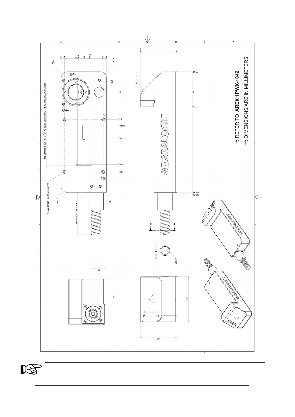
93
NOTE:
Please refer to Datalogic website for detailed drawings.
Page 94

94
FIGURES
Figure 1: Control Rack and Scan Head. ........................................................................................................... vii
Figure 2: Unpacking. ........................................................................................................................................ 10
Figure 3: Transport. ......................................................................................................................................... 12
Figure 4: Positioning rack. ............................................................................................................................... 13
Figure 5: Vertical positioning (need additional fixing). ..................................................................................... 13
Figure 6: Fixing points on shrug rack (cabinet assembly). .............................................................................. 14
Figure 7: Fixing points on Scan Head (vertical mount). .................................................................................. 14
Figure 8: Rack installation environment. ......................................................................................................... 15
Figure 9: Scan Head overview ........................................................................................................................ 18
Figure 10: Control rack overview. .................................................................................................................... 19
Figure 11: Marking area................................................................................................................................... 21
Figure 12: Male panel plug cod. TB4M (front view). ........................................................................................ 22
Figure 13: Female cable mount connector cod. TA4FX (solder view). ........................................................... 23
Figure 14: Female panel socket Sub-D 25 (f ront view) . .................................................................................. 24
Figure 15: ENABLE signal’s scheme. .............................................................................................................. 26
Figure 16: KEY signal’s scheme. ..................................................................................................................... 27
Figure 17: Timing control signals. .................................................................................................................... 27
Figure 18: Timing signals................................................................................................................................. 28
Figure 19: Male panel socket Sub-D 25 (front view). ...................................................................................... 29
Figure 20: Male panel socket Sub-D 9 (front view). ........................................................................................ 30
Figure 21: Female panel socket cod. 09-3482-87-08 (front view). .................................................................. 31
Figure 22: Female panel socket cod. 09-3482-87-04 (front view). .................................................................. 31
Figure 23: Connection example. ...................................................................................................................... 33
Figure 24: Connecting Command Box connector. .......................................................................................... 34
Figure 25: Connecting interlock connector. ..................................................................................................... 35
Figure 26: Connecting power supply cable. .................................................................................................... 36
Figure 27: Ground connection. ........................................................................................................................ 36
Figure 28: USB mouse connection. ................................................................................................................. 37
Figure 29: USB keyboard connection. ............................................................................................................. 37
Figure 30: VGA monitor connection. ............................................................................................................... 38
Figure 31: RJ45 Ethernet connect ion. ............................................................................................................. 38
Figure 32: F-Theta Lens protection cap removal. ........................................................................................... 39
Figure 33: Power on. ....................................................................................................................................... 40
Figure 34: Status LED display. ........................................................................................................................ 40
Figure 35: Enable command KEY. .................................................................................................................. 41
Figure 36: Status LED display. ........................................................................................................................ 41
Figure 37: Enable command ENABLE. ........................................................................................................... 42
Page 95

95
Figure 38: Status LED display. ........................................................................................................................ 42
Figure 39: Control Box (Ordering no: 985330031). ......................................................................................... 64
Figure 40: Kit MOF (Ordering no: 985330027). ............................................................................................... 65
Figure 41: Handles rack................................................................................................................................... 65
Figure 42: Cleaning F-Theta lens. ................................................................................................................... 67
Figure 43: Removal of air filter. ....................................................................................................................... 68
Figure 44: External labels rack location. .......................................................................................................... 71
Figure 45: External labels Scan Head loca tio n. .............................................................................................. 71
Figure 46: Eyeball section. .............................................................................................................................. 78
Page 96

 Loading...