

Page 1
A20 QuickStart Guide
Publication # 843-0111 (Rev U)
About this guide
Thank you for using Datalogic’s A20 cameras. This guide provides a brief overview to help you get started with your new system. For
more detailed instructions, please refer to the Impact Software Reference Guide and A20 Hardware Guide.
Step 1: Unpack and check all the equipment.
Step 2: Mount the camera (see page 3) and connect the Ethernet cable between the camera and the client computer (see page 4).
Step 3: Connect the cable between the camera and the terminal block if you are using the terminal block (see page 4).
Step 4. Wire AC power connections to the power supply input (see page 4).
Step 5. Wire the power supply output to the connector on the terminal block or the unterminated cable connections (see page 4). Turn on
AC power.
Step 6: Configure the client IP address and install the Impact Software (see page 2).
Step 7: Change the A20 and client IP addresses and/or masks, if necessary (see page 2).
Step 8: Connect the terminal block inputs and outputs, or the unterminated cable connectors, to the desired devices (see page 4).
Unpacking the A-Series camera
Extreme temperature precautions: If your system arrives in very cold or hot weather, allow all the equipment to reach room
temperature before plugging it in. Exposing cold equipment to a warm room can cause condensation. If condensation forms, wait for the
equipment to dry completely before plugging it in.
Check the shipping cartons for damage or signs of rough handling or abuse. Notify the shipping company of any damage. Carefully
remove the camera, cabling, and accessories from the shipping package and inspect each item. Save all packing materials so you can
repack the system in case you need to move or ship it.
Camera Operating Specifications
snoisnemiD
thgieW).gk44.(.bl69.
rewoPtupnI).nim(A05.)%01-/+(CD
erutarepmeT
ytidimuH
V42+
An optional power supply is available from Datalogic for the
A20 camera. If you provide your own, it must be a Listed power
supply for the United States and Canada, or a power supply that
meets the requirements for use where either IEC 60950 or
EN60950 is applicable. It must provide the required input power
within the operating specifications listed above.
)sehcni(d549.xh5.5xw876.2
)mm(d42xh7.931xw86
)F221+ot23+(C05+ot0
)gnisnednoc-non(%08ot%02
System Precautions
Follow all warnings and instructions in this guide and in other
user manuals shipped with your hardware components.
To avoid damage to your system and its components, never
plug or unplug a cable when the power is on. Always disconnect
the power supply before making any cable changes.
Never use the system if a power cable has been damaged. Do
not allow anything to rest on a power cable. Keep cables away
from traffic.
The camera should be firmly mounted to a solid surface to
insure the best inspection results. Use the case mounting holes as
illustrated on page 3.
Do not expose any part of your system to moisture, rain, or
snow, and do not use it near water.
To avoid injury, never open the camera case. Opening the case
or removing the tamper-proof sticker will void the product
warranty.
Warning: There are no user-serviceable parts inside the
camera. To avoid electrical shock, never open the case.
Avertissement: Il n’y a aucune pièce d’utilisateur-servicable
à l’intérieur de l’appareil-photo. Pour éviter le choc électrique,
n’ouvrez jamais la valise.
Page 1
Page 2
Installing Impact Software
Camera Characteristics
A client computer is required to install Impact software and configure the vision device. Refer to the A-Series Hardware Guide for
client system requirements.
1. You may need to turn off automatic virus checking during install
if it causes installation problems.
2. You must have administrator privileges to install Impact software.
3. To be able to communicate, the client and camera’s IP addresses
for the local area connection must be configured. The vision
device is shipped with a default IP address of 192.168.0.128 and
a default mask of 255.255.255.0. If you need to change the
camera’s IP address or mask, do so before installation.
4. Insert the Impact software installation CD in the client
computer’s drive and follow the on-screen instructions.
Changing the device IP Address
1. Connect an Ethernet cable from the client computer to the vision
device’s Ethernet connector.
2. Start VPM, select the desired device in the device list and click
Edit IP Address.
3. Enter the desired IP address and IP mask. Leave the Gateway
unchanged. Click OK.
4. When the Reboot Warning is displayed, click OK.
5. You may need to change the client computer’s IP mask and
address so the device and client can communicate. See the
instructions below.
Changing the client IP Address
Windows 7
1. In the Start Menu, select Computer, Network, then click Network
and Sharing Center.
2. Under "View your Active Networks," click Local Area Connection.
3. Click Internet Protocol Version 4 in the list, then click Properties.
4. On the Alternate Configuration tab, select User Configured.
5. Enter the desired IP address and Subnet Mask.
6. Click OK to close all the open dialog windows.
eciveDpu-kciP egamilexip)V(084x)H(257htiwrosneslexipevitcaSOMC
regamI)V(mm88.2x)H(mm15.4-)gaidmm53.5(3/1
etaRerutpaCnacslaitraphtiwrehgih;spfnoituloser-lluf06
eziSlexiPsretemorcim0.6x0.6
niaG%593ot%001
nepOre
ttuhSsdnocesorcim926,391ot03
tnuoMsneLtnuoMC
erawtfoSretaergro0.0.5.7noisreVerawtfoStcapmI
rossecorP)SPIM(dn
epyT
oceSrePsnoitcurtsnInoilliM4331
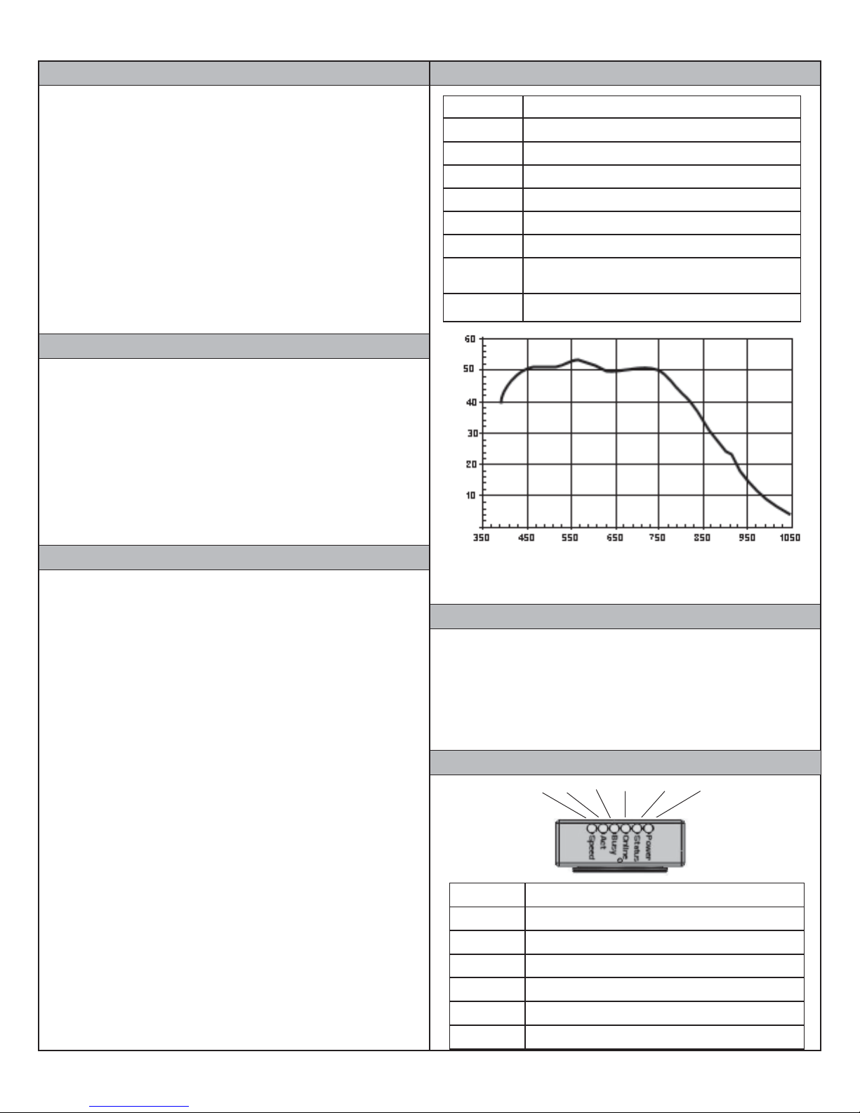
Relative Response
A20 Spectral Response (excludes lens and light source characteristics)
Wavelength (nm)
Resetting the vision device
If it is necessary to reset the vision device, insert the end of an
unfolded paper clip (or similar object with a flat tip), inside the
hole on the rear panel (see page 3). Gently press the reset button.
Vision programs are retained after reset, but the device will be offline.
Windows Vista
1. In the Start Menu, select Network, then click Network and
Sharing Center.
2. For the Local Area Connection, click View Status.
3. Click Internet Protocol Version 4 in the list, then click Properties.
4. On the Alternate Configuration tab, select User Configured.
5. Enter the desired IP address and Subnet Mask.
6. Click OK to close all the open dialog windows.
Windows XP
1. In the Start menu, right click on My Network Places and select
Properties.
2. Right click Local Area Connections and select Properties.
3. On the General tab, select Internet Protocol (TCP/IP) and click
Properties.
4. On the Alternate Configuration tab, select User Configured.
5. Enter the desired IP address and Subnet Mask.
6. Click OK to close all the open dialog windows.
Page 2
Camera Status Lights
BUSY POWERSTATUSSPEED ONLINEACT
emaNsetacidnInO
DEEPS spbM001=wolley,)ylno01A(spbM01=ffo:deepskniltenrehtE
TCAevitcasikniltenrehtE
YSUByrome
ENILNOenilnOsieciveD
SUTATSatadgnissecorpyltnerrucsieciveD
REWOPnOsirewopCDV42
mksidhsalfgnisseccasiaremaC
Page 3

Mounting the Datalogic A20 Camera
The A20 camera should be fastened to a stable, solid surface. Inspection results can be affected if the camera moves. These views show
Side Views
Top View
Bottom View
Rear View
Front View
mounting dimensions, as well as the status light and cable connection locations.
2.658 (67.5)
1/4-20 UNC
6.5 (2)
.473 (12)
UNITS: inch (mm)
.236 (6)
.405 (10.29)
M5/10-32 10mm (x4)
(for mounting optional Dust
Cover Adapter 651-0160)
UNITS: inch (mm)
Reset Button
.945 (24)
2.678 (68)
2.323 (59)
1.162
(29.5)
.616 (15.65)
1.181 (30)
Datalogic Automation, Inc. (DLA) reserves the right to revise this publication from
time to time and to make changes in the content hereof without obligation to notify
any person of such revision or changes.
Under the copyright laws, neither this publication nor the software may be copied,
photocopied, reproduced, or reduced to any electronic medium or machine-readable
form, in whole or in part, without the prior written consent of DLA.
Telephone: 952-996-9500
Facsimile: 952-996-9501
Web site: http://www.datalogic.com
E-Mail: mvsupport@datalogic.com
Impact, Vision Program Manager, VPM, Control Panel Manager, CPM, and A20 are
trademarks of DLA. Microsoft Windows is a trademark of Microsoft Corporation.
Java is a trademark of Sun Microsystems, Inc.
Copyright © 2006-2013 Datalogic Automation, Inc. All Rights Reserved
2.461 (62.5)
5.501 (139.7)
1.339 (34)
4.2 (x4)*
*Through hole from
front side to allow use
of fasteners 4 mm or
less in diameter, M5 or
10-32 threaded on
opposite (back) side.
Page 3
Page 4

Connection Points
lanimreT
rebmuN
emaNlangiS
lanimreT
rebmuN
emaNlangiS
1
2
+nIreggirT
-nIreggirT
31
41
+3tuptuO
-3tuptuO
3
4
+tfihSdna1tupnI
-tfihSdna1tupnI
51
61
+4tuptuO
-4tuptuO
5
6
+tnevEdna2tupnI
-tnevEdna2tupnI
71+rewoPCDV42
7
8
+tuptuOebortS
-tuptuOebortS
81-rewoPCDV42
9
01
+1tuptuO
-1tuptuO
91dnuorGrewoP
11
21
+2tuptuO
-2tuptuO
IMPORTANT NOTE: The Terminal Block power connection terminal
numbers and the Unterminated cable power connection pin numbers are
different.
ff
t
Warning: To
avoid shock
hazard and
possible
personal injury,
do not wire the
terminal block
while power is
connected.
Reset Button
Rear View
Bottom View
Client computer or network - Use only Cat5e or better
Ethernet Cable (Part # 606-0457-xx). A crossover cable is not
required.
Power Supply - See Input/Output Layout
I/O - See Input/Output Layout; Use optional cable (Part # 606-
0607-xx) with terminal block (Part # 248-0138) or optional
unterminated cable (Part # 606-0644-xx)
Serial port - See Input/Output Layout
Input/Output Layout
To connect I/O, use optional cable (Part # 606-0607-02) with
terminal block shown here OR optional unterminated cable (Part #
606-0644-xx) shown below.
Terminated
Cable to A20
Input and Output Characteristics
The single 25-pin Micro D Sub connector provides serial communications and the following inputs and outputs:
1 Camera Trigger Event Input
1 Digital/Shift Input
1 Digital/Event Input
4 Outputs
1 Strobe Output
Strobe output signals on terminals 7 and 8 on the A20 Terminal
Block provide optically isolated, current-mode signals of 300 mA
maximum continuous DC current at 20° C (68° F) – derated at
higher temperatures.
Device Output Characteristics
ylppuS
egatloV
)xam(
CDV62Su052Am003Au001Su05
Page 4
)lanimon(
@Am57.3
cdV21
no-nruT
nO
emiT
)xam(
ffO
tnerruC
tnerruC
)xam(
V42(
Device Input Characteristics
tnerruCtupnI
tupnI
egatloV
62-0
cdV
cdV42@aM5
nO
egatloV
8.2>
cdV
nO
niM
yaleD
nO
tnerruC
Su01Am5.25.1<
ffOnruT
egatloV
05Su
cdV
Serial Cable
I/O Plus
Terminals
I/O Minus
Terminals
+24 VDC Power Plus
Minus
Ground
A20 Terminal Block (Part # 248-0138)
Unterminated Cable wire colors (Part # 606-0644-xx)
yaleDnOnruT
mho-K1otnicd
)daolevitsiser
ffOnruT
OxaM
yaleD
nerruC
Au005
niP
1
2
3
4
5
6
7
8
9
01
11
21
eriW
rebmuN
roloC
nrB/thW
thW/nrB
grO/thW
thW/grO
leY/thW
thW/leY
nrG/thW
tS
thW/nrG
ulB/thW
thW/ulB
oiV/thW
thW/oiV
emaNlangiS
+nIreggirT
-nIreggirT
+tfihS/1tupnI
-tfihS/1tupnI
+tnevE/2tupnI
-tnevE/2tupnI
+tuptuOebor
+1tuptuO
-1tuptuO
+2tuptuO
-2tuptuO
niP
rebmuN
31
41
51
61
71
81
91
-tuptuOebortS
02
12
22
32
42
52
eriW
roloC
yrG/t
hW
thW/yrG
kniP/thW
thW/kniP
uO
naT/thW
thW/naT
nrB/naT
naT/nrB
grO/naT
naT/grO
leY/naT
naT/leY
kniP/naT
emaNlangiS
+3tuptuO
-3tuptuO
+4tuptuO
-4tupt
+rewoP
+rewoP
-rewoP
-rewoP
dnuor
GrewoP
dnuorGrewoP
timsnarTlaireS
aireS
evieceRl
dnuorGlaireS
 Loading...