

Page 1

Magellan
TM
9800i
Product Reference Guide
Page 2

Datalogic ADC, Inc.
959 Terry Street
Eugene, OR 97402
USA
Telephone: (541) 683-5700
Fax: (541) 345-7140
© 2012-2014 Datalogic ADC, Inc.
An Unpublished Work - All rights reserved. No part of the contents of thi
be reproduced or transmitted in any form or by any means without prior written permission of Datalogic ADC, Inc. or its subsidiaries or affiliates ("Datalogic" or "Datalogic ADC"). Owners of Datalogic products are hereby granted a non-exclusive, revocable license
to reproduce and transmit this documentation for the purchaser's own internal business purposes. Purchaser shall not remove or
alter any proprietary notices, including copyright notices, contained in this documentation and shall ensure that all notices appear
on any reproductions of the documentation.
Should future revisions of this manual be published, you can acqui
Electronic versions may either be downloadable from the Datalogic website (www.datalogic.com) or provided on appropriate
media. If you visit our website and would like to make comments or suggestions about this or other Datalogic publications, please
let us know via the "Contact Datalogic" page.
Disclaimer
Datalogic has taken reasonable measures to provide information in this manual
reserves the right to change any specification at any time without prior notice.
Datalogic and the Datalogic logo are registered trademarks of Datalogic S.p.A. in many countries, including the U.S.A. and the E.U.
All other brand and product names may be trademarks of their respective owners.
Magellan is a registered trademark of Datalogic ADC, Inc. in many countries, including the U.S.A. and All-Weighs, FirstStrike and
SurroundScan are registered
and SmartSentry are all trademarks of Datalogic ADC, Inc.
trademarks of Datalogic ADC, Inc. in the U.S.A. OmegaTek, Produce Rail, Productivity Index Reporting
s documentation or the procedures described therein may
re printed versions by contacting your Datalogic representative.
that is complete and accurate, however, Datalogic
This product may be covered by one or more of the following patents:
Design Patents: EP002139097, ZL201230602464.1
Utility Patents: CA2492693C, EP0789315B1, EP1114391B1, EP1307854B1, EP1330772B1, EP1479054B1, EP1481378B1,
97521B1, EP1828957B1, EP1890272B1, EP2287817B1, US5834708, US5837983, US5992740, US6478224, US6499662,
EP17
US6561427, US6585157, US6705527, US6729603, US6783072, US6857567, US6877663, US6917723, US7108170, US7132947,
US7170414, US7172123, US7201322, US7204422, US7234641, US7299975, US7374092, US7407096, US7495564, US7506816,
US7527198, US7562817, US7619527, US8006904, US8011579, US8172145, US8245926, US8261990, US8358211, US8488210,
USRE40071, ZL200780018182.3, ZL200880117067.6
Additional patents pending.
Page 3

Table of Contents
Chapter 1. Introduction ................................................................................................................ 1
Manual Overview.........................................................................................................................................................2
How to Use This Manual..................................................................................................................................3
Scanner Nomenclature..............................................................................................................................................4
Connectors and Ports.......................................................................................................................................5
Physical Parameters ....................................................................................................................................................7
Scanning ...............................................................................................................................................................7
EAS Tag Deactivation System........................................................................................................................7
Weighing ..............................................................................................................................................................8
Scale SentryTM Option......................................................................................................................................8
Warm-Up Time....................................................................................................................................................9
Electrical Specifications .......................................................................................................................................... 10
Power Supply ................................................................................................................................................... 10
Safety Precautions.......................................................................................................................................... 11
Labeling........................................................................................................................................................................ 12
Agency Compliances............................................................................................................................................... 13
Bar Codes Supported............................................................................................................................................... 15
1D Symbologies .............................................................................................................................................. 15
2D Symbologies .............................................................................................................................................. 15
Technical Support..................................................................................................................................................... 16
Datalogic Website Support......................................................................................................................... 16
Reseller Technical Support.......................................................................................................................... 16
Telephone Technical Support.................................................................................................................... 16
Chapter 2. Site Preparation and Installation ............................................................................ 17
Installing the Optional TDR ................................................................................................................................... 18
Pre-Installation Considerations............................................................................................................................ 20
Checkstand Design Recommendations ........................................................................................................... 21
Scanner Installation.................................................................................................................................................. 22
Scanner Maintenance.............................................................................................................................................. 22
References ................................................................................................................................................................... 22
Scanner Usage ........................................................................................................................................................... 22
Site Preparation Overview..................................................................................................................................... 23
Ventilation and Spacing ......................................................................................................................................... 26
Service Access ............................................................................................................................................................ 26
Power Installation..................................................................................................................................................... 27
Grounding......................................................................................................................................................... 27
Product Reference Guide
i
Page 4

Checkstand Preparation ......................................................................................................................................... 27
Liquid Spills and Moisture ........................................................................................................................... 27
Counter Cutout.......................................................................................................................................................... 28
Checkstand Mounting................................................................................................................................... 34
Installation Overview............................................................................................................................................... 34
Unpacking ......................................................................................................................................................... 35
Operational Verification ...............................................................................................................................36
Diagnostic Modes ........................................................................................................................................... 38
Cables & Connections.................................................................................................................................... 40
Remote Scale Display Placement/Installation ................................................................................................ 42
Lighting Considerations ............................................................................................................................... 42
Viewing Angle.................................................................................................................................................. 42
Remote Display Cabling ............................................................................................................................... 43
Placing and Installing the Remote Display............................................................................................ 43
Changing Weighing Modes ........................................................................................................................45
Set-Up & Installation ................................................................................................................................................ 45
Set-up.................................................................................................................................................................. 45
System Power-Up Recap ........................................................................................................................................49
Chapter 3. Operation and Maintenance ................................................................................... 51
Scanning Items ................................................................................................................................................ 51
Proper Weighing Technique (Scale Models)......................................................................................... 52
Deactivating Security Labels....................................................................................................................... 53
Operational Controls ...............................................................................................................................................54
Operational Modes...................................................................................................................................................54
Power-Up/Selftest & Pre-Operation ......................................................................................................... 54
Operating Mode.............................................................................................................................................. 55
Additional Functions ............................................................................................................................................... 56
Programming ...................................................................................................................................................56
Diagnostic Mode............................................................................................................................................. 56
Scanner and Scale Reset............................................................................................................................... 56
Scale Adjustments .......................................................................................................................................... 57
Operational Maintenance...................................................................................................................................... 58
Vertical Scan Window Replacement........................................................................................................ 58
Horizontal Scan Window Replacement (DLC) ......................................................................................60
Chapter 4. TDR, Camera and Mobile Commerce ...................................................................... 61
Optional TDR Feature .............................................................................................................................................. 61
Camera Feature..........................................................................................................................................................62
Mobile Commerce Reader ..................................................................................................................................... 62
Chapter 5. Problem Isolation ..................................................................................................... 63
Diagnostic Procedures ............................................................................................................................................ 64
Error Codes .................................................................................................................................................................. 64
Scale Error Reporting............................................................................................................................................... 67
Flowcharts ................................................................................................................................................................... 68
Chapter 6. Calibration Procedures ............................................................................................ 75
Description of Calibration Sequence................................................................................................................. 76
ii
Magellan™ 9800i Scanner
Page 5

Motion Test ................................................................................................................................................................. 76
Automatic Zero Setting Test................................................................................................................................. 77
Preparing the Scanner/Scale for Calibration................................................................................................... 77
Calibrating the Scale (Pounds & Kilograms).................................................................................................... 78
Calibration Verification (Pounds) ........................................................................................................................ 80
Calibration Verification (Kilograms) ................................................................................................................... 85
Chapter 7. Programming ........................................................................................................... 91
Introduction to Label Programming.................................................................................................................. 91
Understanding the Basics...................................................................................................................................... 91
Using a Bar Code Mask.................................................................................................................................. 91
Going Green ..................................................................................................................................................... 91
Bar Code Mask ................................................................................................................................................. 92
Integrating the Scanner With Your Host System........................................................................................... 93
Customizing Your Scanner’s Operation............................................................................................................ 93
Programming Overview ......................................................................................................................................... 94
Programming via Handheld Device......................................................................................................... 94
What Is Programming Mode?..................................................................................................................... 94
Entering and Exiting Programming Mode. ........................................................................................... 94
Programming Session................................................................................................................................... 95
Programming Sequence .............................................................................................................................. 96
LED and Beeper Indicators .......................................................................................................................... 98
If You Make a Mistake.................................................................................................................................... 98
Test Mode.......................................................................................................................................................... 99
Chapter 8. Imaging Features ................................................................................................... 101
Top Down Reader (TDR) and Mobile Commerce Imaging Features ....................................................101
Mobile Commerce Reader Enable ....................................................................................................................102
Mobile Commerce Imagers.................................................................................................................................103
Mobile Commerce Button Function ......................................................................................................104
TDR Enable ................................................................................................................................................................105
Image Camera..........................................................................................................................................................106
Image Format...........................................................................................................................................................107
Image Size .................................................................................................................................................................108
Image Brightness ....................................................................................................................................................109
Image Contrast ........................................................................................................................................................111
Chapter 9. General Scanner and Scale Features .................................................................... 113
1D Double Read Timeout..................................................................................................................................... 113
2D Double Read Timeout..................................................................................................................................... 114
Label Gone Timeout ..............................................................................................................................................115
Sleep Mode Timer...................................................................................................................................................116
1D Inverse Read Control.......................................................................................................................................117
2D Inverse Read Control.......................................................................................................................................118
Illumination Control...............................................................................................................................................118
2D Contrast Improvement...................................................................................................................................119
Good Read LED Idle State ....................................................................................................................................120
Scanner Control Button Options....................................................................................................................... 121
Power-up Tone Control ........................................................................................................................................122
Product Reference Guide
iii
Page 6

Good Read Beep Control......................................................................................................................................123
Good Read Beep Frequency................................................................................................................................124
Good Read Beep Length.......................................................................................................................................125
Good Read Beep Volume .....................................................................................................................................126
Good Read When to Indicate..............................................................................................................................127
Scale Zero Button and Scale Indicator LED....................................................................................................128
Scale Sentry...............................................................................................................................................................129
Scale Sentry Block Weight Transmission..............................................................................................130
Scale Sentry Override Button ...................................................................................................................131
Scale Enable ..............................................................................................................................................................132
Scale Diagnostics Mode........................................................................................................................................133
Scale Stale Weight Timeout ......................................................................................................................134
Scale Enforced Zero Return.......................................................................................................................135
Scale Interface Type .....................................................................................................................................136
Scale Calibration Notification...................................................................................................................138
Scale Intercharacter Delay .........................................................................................................................139
Remote Display — Enable/Disable...................................................................................................................140
Auxiliary Port Mode................................................................................................................................................141
Auxiliary USB Mode ................................................................................................................................................142
Productivity Index Reporting (PIR) / Cashier Training (CT) ......................................................................143
PIR/CT Auxiliary Port Baud Rate...............................................................................................................144
Chapter 10. EAS Features ........................................................................................................ 147
EAS Features — Sensormatic..............................................................................................................................147
EAS Mode.........................................................................................................................................................148
EAS Notification.............................................................................................................................................150
EAS Security Level.........................................................................................................................................151
EAS Good Beep Mode .................................................................................................................................152
EAS Beep Duration .......................................................................................................................................153
EAS Retry Count.............................................................................................................................................154
EAS Exception Button..................................................................................................................................155
EAS Deactivation Duration — Coupled................................................................................................156
EAS Deactivation Duration — Retry.......................................................................................................157
EAS Deactivation Duration — Exception .............................................................................................158
EAS Pre-Read Time .......................................................................................................................................159
EAS Features — Checkpoint ...............................................................................................................................160
ERI Active State ..............................................................................................................................................160
ERI Timeout .....................................................................................................................................................161
Chapter 11. Interface Related Features .................................................................................. 163
Interface Type...........................................................................................................................................................163
RS-232 Interface Selection.........................................................................................................................165
USB Interface Selection...............................................................................................................................166
IBM Interface Selection ...............................................................................................................................167
Keyboard Interface Selection....................................................................................................................168
Maximum Host-Transmitted Message Length.............................................................................................169
IBM Features .............................................................................................................................................................170
IBM Interface Options..................................................................................................................................170
IBM Scale Address.........................................................................................................................................171
iv
Magellan™ 9800i Scanner
Page 7

IBM Transmit Labels in Code 39 Format...............................................................................................172
46XX Number of Host Resets.................................................................................................................... 173
46XX Label Slicing Control ........................................................................................................................174
46XX Maximum Label Slice Length........................................................................................................175
USB OEM Interface Options.................................................................................................................................176
USB OEM Scanner Device Type ...............................................................................................................177
RS-232 Features.......................................................................................................................................................178
RS-232 Baud Rate..........................................................................................................................................178
RS-232 Number of Data Bits......................................................................................................................180
RS-232 Number of Stop Bits......................................................................................................................181
RS-232 Parity................................................................................................................................................... 182
RS-232 Hardware Control ..........................................................................................................................183
RS-232 Intercharacter Delay .....................................................................................................................184
RS-232 Software Flow Control .................................................................................................................185
RS-232 Ignore Host Commands ..............................................................................................................186
RS-232 TTL.......................................................................................................................................................187
RS-232 TTL Invert ..........................................................................................................................................188
RS-232 Beep on ASCII BEL..........................................................................................................................189
RS-232 Beep After Weigh...........................................................................................................................190
Beep on Not on File......................................................................................................................................191
RS-232 ACK NAK Enable .............................................................................................................................192
RS-232 ACK Character .................................................................................................................................193
RS-232 NAK Character.................................................................................................................................194
RS-232 Retry on ACK NAK Timeout ........................................................................................................195
RS-232 ACK NAK Timeout Value..............................................................................................................196
RS-232 ACK NAK Retry Count ...................................................................................................................197
RS-232 ACK NAK Error Handling..............................................................................................................198
RS-232 Indicate Transmission Failure....................................................................................................199
Single Cable RS-232 Options ..............................................................................................................................200
Single Cable RS-232 Scanner Only Protocol .......................................................................................201
Single Cable RS-232 RTS CTS Selection.................................................................................................202
Single Cable RS-232 Use BCC ...................................................................................................................204
Single Cable RS-232 Use ACK/NAK.........................................................................................................205
Single Cable RS-232 Use STX ....................................................................................................................206
Set Single Cable RS-232 STX Character.................................................................................................207
Single Cable RS-232 Use ETX ....................................................................................................................208
Set Single Cable RS-232 ETX Character.................................................................................................209
Single Cable RS-232 Datalogic Extensions ..........................................................................................210
Single Cable RS-232 Pacesetter Plus......................................................................................................211
USB Keyboard and Keyboard Wedge Features............................................................................................212
USB Keyboard and Keyboard Wedge Intercharacter Delay ..........................................................212
Keyboard Wedge No Keyboard Support..............................................................................................213
USB Keyboard and Keyboard Wedge Send Control Characters ..................................................214
USB Keyboard and Keyboard Wedge Country Mode......................................................................215
Keyboard Wedge Quiet Interval..............................................................................................................219
USB Keyboard and Keyboard Wedge Caps Lock State ...................................................................220
Chapter 12. Data Editing .......................................................................................................... 221
Data Editing Overview ..........................................................................................................................................221
Product Reference Guide
v
Page 8

Please Keep In Mind.....................................................................................................................................222
Case Conversion ......................................................................................................................................................222
Character Conversion............................................................................................................................................223
Global Prefix..............................................................................................................................................................224
Global Suffix..............................................................................................................................................................225
Global AIM ID Enable .............................................................................................................................................226
Label ID Control.......................................................................................................................................................227
Label ID .......................................................................................................................................................................228
1D Symbologies ............................................................................................................................................228
2D Symbologies ............................................................................................................................................233
Global Mid-Label ID................................................................................................................................................234
Chapter 13. 1D Symbology Programming ............................................................................. 235
1D Symbologies.......................................................................................................................................................235
Coupon Control.............................................................................................................................................236
UPC-A Enable............................................................................................................................................................237
UPC-A Number System Character Transmission ...............................................................................238
UPC-A Check Character Transmission ...................................................................................................239
UPC-A Minimum Read.................................................................................................................................240
Expand UPC-A to EAN-13...........................................................................................................................241
UPC-E Enable ............................................................................................................................................................242
UPC-E Number System Character Transmission................................................................................243
UPC-E Check Character Transmission....................................................................................................244
Expand UPC-E to UPC-A..............................................................................................................................245
Expand UPC-E to EAN-13............................................................................................................................246
UPC-E Minimum Read .................................................................................................................................247
EAN-13 Enable..........................................................................................................................................................248
EAN-13 First Character Transmission.....................................................................................................249
EAN-13 Check Character Transmission.................................................................................................250
EAN-13 ISBN Conversion Enable .............................................................................................................251
EAN-13 Minimum Read...............................................................................................................................252
EAN-8 Enable ............................................................................................................................................................253
EAN-8 Check Character Transmission....................................................................................................254
Expand EAN-8 to EAN-13 ...........................................................................................................................255
EAN-8 Minimum Read .................................................................................................................................256
EAN-8 Guard Insertion ................................................................................................................................257
EAN-8 Guard Substitution..........................................................................................................................258
EAN-8 Stitch Exact Label Halves ..............................................................................................................259
EAN-8 Stitch Unlike Label Halves ............................................................................................................260
Other UPC/EAN Options.......................................................................................................................................261
In-Store Printed Label Minimum Read..................................................................................................262
UPC/EAN Reconstruction...........................................................................................................................263
UPC/EAN Correlation...................................................................................................................................264
UPC/EAN Guard Insertion ..........................................................................................................................265
UPC/EAN Stitch Exact Label Halves........................................................................................................266
UPC/EAN Stitch Unlike Label Halves......................................................................................................267
UPC/EAN Minimum Segment Length ...................................................................................................268
Price Weight Check ......................................................................................................................................270
Enable EAN Two Label ................................................................................................................................272
vi
Magellan™ 9800i Scanner
Page 9

EAN Two Label Minimum Read ...............................................................................................................273
Addons .............................................................................................................................................................274
GTIN Enable...............................................................................................................................................................281
GS1 DataBar ..............................................................................................................................................................282
DataBar Omnidirectional Enable.......................................................................................................................282
DataBar Omnidirectional/EAN-128 Emulation...................................................................................283
DataBar Omnidirectional 2D Component Enable.............................................................................284
DataBar Omnidirectional Minimum Read............................................................................................285
DataBar Expanded Enable ...................................................................................................................................286
DataBar Expanded EAN-128 Emulation................................................................................................287
DataBar Expanded 2D Component Enable.........................................................................................288
DataBar Expanded Minimum Read ........................................................................................................289
DataBar Expanded Length Control ........................................................................................................290
DataBar Expanded Length 1.....................................................................................................................291
DataBar Expanded Length 2.....................................................................................................................292
Code 39 Enable........................................................................................................................................................ 293
Code 39 Start Stop Character Transmission........................................................................................294
Code 39 Check Character Calculation...................................................................................................295
Code 39 Check Character Transmission ...............................................................................................296
Code 39 Full ASCII.........................................................................................................................................297
Code 39 Minimum Read.............................................................................................................................298
Code 39 Correlation.....................................................................................................................................299
Code 39 Length Control.............................................................................................................................300
Code 39 Length 1.......................................................................................................................................... 301
Code 39 Length 2.......................................................................................................................................... 302
Code 39 Stitching .........................................................................................................................................303
Code 39 Require Margins...........................................................................................................................304
Code 32 Italian Pharmacode Enable................................................................................................................305
Code 32 Start Stop Character Transmission........................................................................................306
Code 32 Check Character Transmission ...............................................................................................307
Code 128 Enable .....................................................................................................................................................308
Code 128 Transmit Function Characters..............................................................................................309
Expand Code128 to Code 39....................................................................................................................310
Code 128 Minimum Read ..........................................................................................................................311
Code 128 Correlation ..................................................................................................................................312
Code 128 Length Control ..........................................................................................................................313
Code 128 Length 1.......................................................................................................................................314
Code 128 Length 2.......................................................................................................................................315
Code 128 Stitching.......................................................................................................................................316
EAN-128 Enable.......................................................................................................................................................317
Interleaved 2 of 5 (I 2 OF 5) Enable...................................................................................................................318
I 2 of 5 Check Character Calculation ......................................................................................................319
I 2 of 5 Check Character Transmission...................................................................................................320
I 2 of 5 Minimum Read ................................................................................................................................321
I 2 of 5 Correlation ........................................................................................................................................322
I 2 of 5 Length Control ................................................................................................................................323
I 2 of 5 Length 1.............................................................................................................................................324
I 2 of 5 Length 2.............................................................................................................................................325
I 2 of 5 Stitching.............................................................................................................................................326
Product Reference Guide
vii
Page 10

Codabar Enable........................................................................................................................................................327
Codabar Start Stop Character Transmission .......................................................................................328
Codabar Start Stop Character Set ...........................................................................................................329
Codabar Start Stop Character Match.....................................................................................................330
Codabar Check Character Calculation...................................................................................................331
Codabar Check Character Transmission...............................................................................................332
Codabar Minimum Read ............................................................................................................................333
Codabar Correlation ....................................................................................................................................334
Codabar Length Control.............................................................................................................................335
Codabar Length 1 .........................................................................................................................................336
Codabar Length 2 .........................................................................................................................................337
Codabar Stitching.........................................................................................................................................338
Codabar Require Margins ..........................................................................................................................339
Code 93 Enable ........................................................................................................................................................340
Code 93 Minimum Read.............................................................................................................................341
Code 93 Correlation .....................................................................................................................................342
Code 93 Length Control .............................................................................................................................343
Code 93 Length 1..........................................................................................................................................344
Code 93 Length 2..........................................................................................................................................345
Code 93 Stitching..........................................................................................................................................346
MSI Enable .................................................................................................................................................................347
MSI Check Character Calculation ............................................................................................................348
MSI Number of Check Characters ...........................................................................................................349
MSI Check Character Transmission.........................................................................................................350
MSI Minimum Read ......................................................................................................................................351
MSI Correlation ..............................................................................................................................................352
MSI Length Control ......................................................................................................................................353
MSI Length 1...................................................................................................................................................354
MSI Length 2...................................................................................................................................................355
MSI Stitching...................................................................................................................................................356
Standard 2 of 5 Enable ..........................................................................................................................................357
Standard 2 of 5 Check Character Calculation .....................................................................................358
Standard 2 of 5 Check Character Transmission..................................................................................359
Standard 2 of 5 Minimum Read ...............................................................................................................360
Standard 2 of 5 Correlation .......................................................................................................................361
Standard 2 of 5 Length Control ...............................................................................................................362
Standard 2 of 5 Length 1............................................................................................................................363
Standard 2 of 5 Length 2............................................................................................................................364
Standard 2 of 5 Stitching............................................................................................................................365
Chapter 14. 2D Symbology Programming ............................................................................. 367
2D Symbologies.......................................................................................................................................................367
Data Matrix Enable .................................................................................................................................................368
Data Matrix Length Control ......................................................................................................................369
Data Matrix Length 1, Length 2 Programming Instructions .........................................................370
PDF 417 Enable ........................................................................................................................................................371
PDF 417 Length Control .............................................................................................................................372
PDF 417 Length 1, Length 2 Programming Instructions ................................................................373
PDF 417 Read Option.............................................................................................................................................374
viii
Magellan™ 9800i Scanner
Page 11

Micro PDF 417 Enable ...........................................................................................................................................375
Micro PDF 417 Length Control ................................................................................................................376
Micro PDF 417 Length 1, Length 2 Programming Instructions ...................................................377
Micro PDF 417 128 Emulation............................................................................................................................378
QR Code Enable.......................................................................................................................................................379
QR Code Length Control............................................................................................................................380
QR Code Length 1, Length 2 Programming Instructions...............................................................381
Micro QR Code Enable ..........................................................................................................................................382
Micro QR Code Length Control ...............................................................................................................383
Micro QR Code Length 1, Length 2 Programming Instructions ..................................................384
Aztec Enable .............................................................................................................................................................385
Aztec Length Control ..................................................................................................................................386
Aztec Length 1, Length 2 Programming Instructions .....................................................................387
Appendix A. LED/Audio Indications & Controls...................................................................... 389
Good Read Indicators............................................................................................................................................389
Controls and Indicators ........................................................................................................................................390
LED and Audio Indications........................................................................................................................391
ScaleSentry / Scale Service Button .........................................................................................................394
Sensormatic EAS Button.............................................................................................................................395
Camera Button...............................................................................................................................................395
Mobile Commerce Button.........................................................................................................................395
Scanner Control Button..............................................................................................................................396
Scale Zero Button .........................................................................................................................................397
Calibration Switch ........................................................................................................................................398
Appendix B. Cable Information................................................................................................ 399
Introduction..............................................................................................................................................................399
General Specifications ................................................................................................................................399
External Cable Pinouts ..........................................................................................................................................400
Appendix C. Keypad..................................................................................................................403
Appendix D. microSD Card ....................................................................................................... 405
microSDHC Compatibility....................................................................................................................................405
microSD Card Insertion.........................................................................................................................................405
microSD Card Removal............................................................................................................................... 406
Autorun File Processing........................................................................................................................................407
microSD Function Summary...............................................................................................................................407
microSD Function Details ....................................................................................................................................408
From Scanner to microSD Card ...............................................................................................................408
From microSD Card to Scanner ...............................................................................................................410
Appendix E. Host Commands...................................................................................................411
Accepting Commands from an RS-232 Scanner Host ...............................................................................411
Appendix F. Factory Defaults ...................................................................................................413
Product Reference Guide
ix
Page 12

Appendix G. Handheld Data Format Requirements .............................................................. 427
Handheld Data Format Requirements General .................................................................................427
Datalogic Handheld Data Format Requirements..............................................................................428
AIM Formats....................................................................................................................................................433
x
Magellan™ 9800i Scanner
Page 13

Chapter 1
Introduction
This manual provides details for installation, configuration, calibration and operation of the
scanner or scanning-scale.
For the purposes of this manual, any Magellan 98xx model may be termed
as simply “scanner” (including scanning-scale models).
Because of differences due to multiple model types and options, the llus-
NOTE
trations shown in this manual may vary from the model(s) in use at your
tion.
loca
Product Reference Guide
1
Page 14

Introduction
Manual Overview
Chapter 1, Introduction, presents the manual’s contents, describes features and specifications,
provides regulatory and safety information, and lists the bar code symbologies the scanner will
read.
Chapter 2, Site Preparation and Installation, supplies physical dimensions for the scanner or
scanning-scale and its most common accessories, and details counter preparation and
installation. Cable routing, connection and testing are also explained in this section.
Chapter 3, Operation and Maintenance, describes use and maintenance; providing details about
operator controls, programming and diagnostic modes, scale “zeroing” and calibration. Scanner
and scale routine maintenance are outlined in this section as well.
Chapter 4, TDR, Camera and Mobile Commerce, defines the functions of the optional Top
Down Reader, Camera and Mobile Commerce Reader features.
Chapter 5, Problem Isolation, provides an outline of three scanning-scale test modes: Selftest,
Operational Tests and Diagnostic Tests. Descriptions of the error indications if the scanner
detects a system problem and troubleshooting flowcharts to aid in problem resolution are also
presented.
Chapter 6, Calibration Procedures, explains scale calibration and verification procedures,
including procedures for calibrating the scale in pounds as well as kilograms.
Chapter 7, Programming, and subsequent chapters detail procedures and provide custom bar
codes for setting programmable scanner and scanning-scale features.
Appendix A, LED/Audio Indications & Controls, lists the various functions and indications of
the scanner’s control panel features.
Appendix B, Cable Information, outlines wire requirements, connector specifications and
pinout details for associated product cabling.
Appendix C, Keypad, furnishes bar codes representing the digits and characters required to
enter extended programming data needed during certain programming sessions.
Appendix D, microSD Card, describes the use and functions of the microSD Card Slot.
Appendix E, Host Commands, contains a partial listing of available host commands that can be
used with a compatible host interface.
Appendix F, Factory Defaults, provides a listing of factory default settings based on the most
common interface.
Appendix G, Handheld Data Format Requirements, specifies additional references for use when
a handheld scanner is connected to the scanner.
2
Magellan™ 9800i Scanner
Page 15
How to Use This Manual
LEGAL NOTE
You’ll find it helpful to familiarize yourself with the first section of this manual, since it provides
both a general description of the product’s features and an overview of the manual’s contents
and organization. Reference the other sections as required for information about scanner or
scanning-scale installation, operation, maintenance, calibration and bar code programming.
Manual Conventions
‘NOTE’ blocks contain information that is helpful and
recommended. They provide information that is critical
to operations and/or procedures described in this manual.
‘LEGAL NOTE’ blocks indicate procedures or activities
which may be regulated under law by governmental
agencies. It is your responsibility to ensure compliance
with the regulations that govern installation of weighing devices.
‘CAUTION’ blocks inform you that proper handling
(adherence to the procedures described) is required to
avoid damage to equipment and/or property.
‘WARNING’ blocks alert you to potential physical harm
or injury. These statements do not include potentially
fatal hazards, which would be designated as ‘DANGER’
blocks. Use of this product does not warrant the need
for a DANGER block.
Product Reference Guide
3
Page 16
Introduction
1
2
2
3 3
6
87
9
5
4
with Platter without Platter
7
9
10
1
9
11
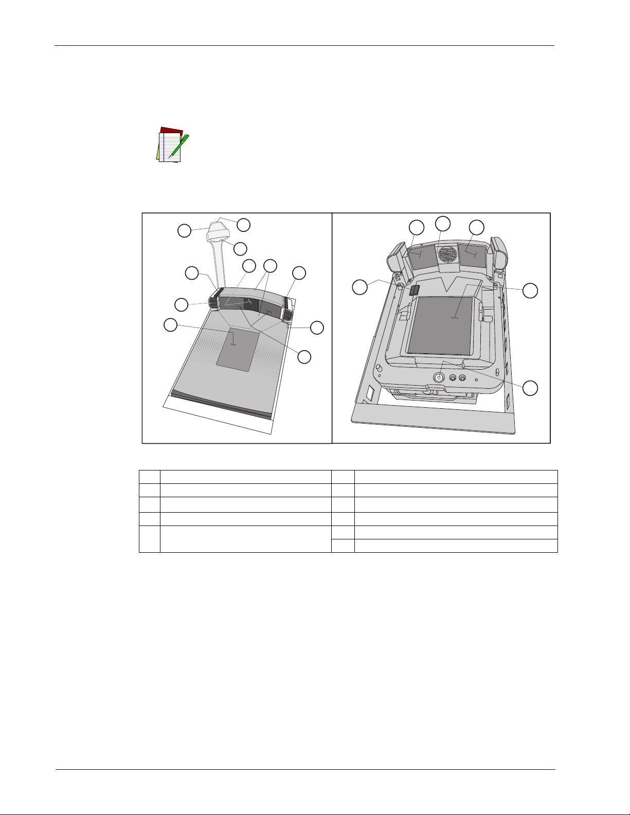
Scanner Nomenclature
The parts and features of the scanner are shown in Figure 1. Control Panel buttons and
indicators are described in more detail in Appendix A
Optional features include the Scale (for weighing items)
Top Down Reader (TDR) and Electronic Article Survellance (EAS). Your scanner may or may not support all of
NOTE
Figure 1. Scanner Nomenclature
these capa
.
bilities.
1
Horizontal Scan Window
2
Control Panels
3
Good Read Indicator LED
4
Mobile Commerce Reader (optional)
Mobile Commerce/Camera Indica-
5
tor LED
6
Top Down Reader (TDR) (optional)
7
Speaker
8
All WeighsTM Platter
9
Vertical Scan Windows
10
Service Port Cover (microSD and USB test)
11
Bubble Level
4
Magellan™ 9800i Scanner
Page 17
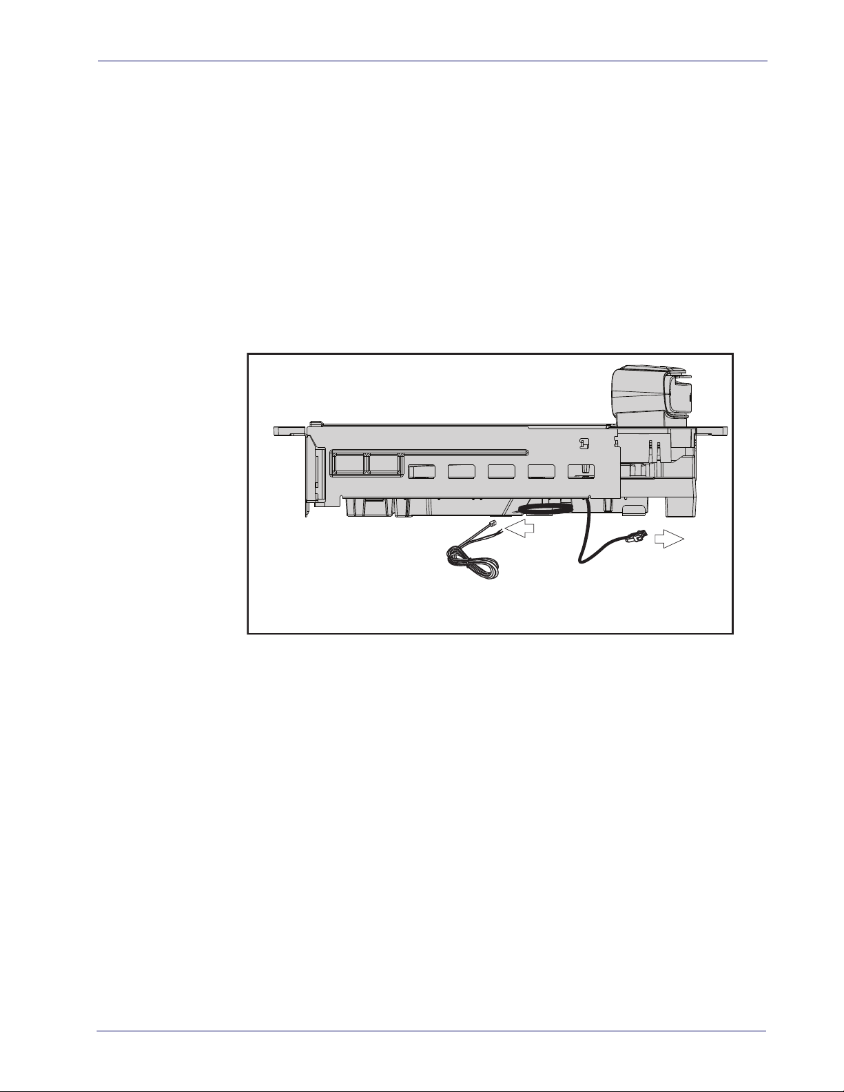
Connectors and Ports
Connector port availability and appearance will differ between models, since these optional
features may sometimes be added at the time of purchase. See the illustrations in Figure 1,
Figure 2 and Figure 3.
• Checkpoint
• Sensormatic
• Scale (weighing) Feature
• Remote Display Accessory (for models with a scale)
• Top Down Reader (TDR) / Camera
• microSD Card Reader (item #10 in Figure 1)
• USB Service Port (item #10 in Figure 1)
Figure 2. Optional EAS Cable Connections
®
Electronic Article Survellance (EAS) Feature
®
Electronic Article Survellance (EAS) Feature
/ Mobile Commerce Features
To Checkpoint
EAS System
®
EAS System
To Sensormatic
®
Product Reference Guide
5
Page 18
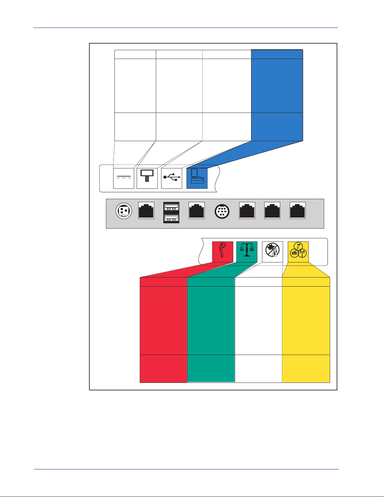
Introduction
SCALE HOSTTOP DOWN READER
Connector Bulkhead
Scale Data (dual
cable scanner/scale)
Connection to
this port is
Optional
· Expands the scan
zone by scanning an
item’s fifth side.
· E-commerce bar code
reading.
· Captures photo
images.
Dual cable units only.
(Scale connection may
be handled through
POS Terminal port)
Aux. PortEAS InterlockTDR Scale Host
Remote Display
0.00
Power POS TerminalUSB Port
HOST PORTREMOTE DISPLAYPOWER
Connection to
these ports is
Optional
AC Brick Input
OR
Power off Terminal
(POT) Brick Input
Drives Remote Display · Label Data
· Scale Data (for
single cable interfaces)
· Application Download
(where appropriate)
USB PORTS
· USB Handheld
Scanner Input
· USB-to-Serial adapter
used for scale cali bration testing.
Models with scale
only
AUXILIARY PORT
Connection to
this port is
Optional
Connection to
this port is
Optional
· Application Download
to attached RS-232
Handheld Scanner
· Provides Good Read
output to enable EAS
antenna RF output
EAS
Figure 3. Connector Panel
6
Magellan™ 9800i Scanner
Page 19

Physical Parameters
1
2
5
6
3
4
This section provides specifications for performance, environmental and electrical parameters.
Reference the second section of this manual, Site Preparation and Installation, for physical
measurements of all models and some accessories.
Scanning
A scan zone (Figure 4) exists in the area between the horizontal and vertical scan windows, and
the Top Down Reader (TDR), if that optional feature is present. Separate projections
of these sources combine to form a zone where bar code labels are read. Refer to the Operation
and Maintenance section of this manual for more details about the topic: Scanning Items.
Figure 4. Scan Zone
from each
1
Horizontal Scan Zone
2
Vertical Scan Zone
3
Optional TDR Scan Zone
4
Optional Mobile Commerce Scan Zone
5
Combined Scan Zone
Move items through the center of the hor-
6
izontal window for best scan coverage
EAS Tag Deactivation System
Scanners can be ordered from the factory to include an optional EAS (Electronic Article
Surveillance) deactivation system. Two different EAS system types are available: Checkpoint
2
and Sensormatic
The Sensormatic
Chapter 3, "Deactivating Security Labels" for more information about its use.
Contact Technical Support for information about installation of the Sensormatic
ScanMaxPro EAS controller box. Additional details about
.
®
deactivation system requires connection as shown in Figure 2a. Reference
AMB-9010 or
this system can be referenced under
the following topics:
• Chapter 3, "Deactivating Security Labels"
• Chapter 7, "EAS Features — Sensormatic"
1. Checkpoint is a registered trademark of Checkpoint Systems, Inc
2. Sensormatic is a registered trademark of Sensormatic Electronics Corporation.
Product Reference Guide
7
1
Page 20

Introduction
Weighing
Specifications for scale capacity, settling time, minimum and maximum static weight, zeroing,
and warm-up time are given below. For more information regarding the topic:
Te c h n i qu e , refer to the Operation and Maintenance section of this manual.
Proper Weighing
Rated Weight Capacity
The scale’s operational weight capacity is:
• 30.00 pounds, displayed in 0.01 increments
OR
• 15.000 kilograms1, displayed in 0.005 increments.
Minimum Weight
The minimum weight that can be accurately measured by the scale is 0.02 lb. (0.005 kg).
Maximum Static Weight (Overload)
A maximum static weight of 150 pounds (68 kg) can be sustained by the scale without incurring
damage or degrading performance.
Automatic Zero Maintenance
The scale’s software constantly monitors and adjusts the Zero point as long as the deviation is
within acceptable limits
power-up, the scale automatically re-zeros after verifying that all subsystems are functional.
Additionally, the scale may be manually “zeroed” by pushing the Scale Zero Button located on
the control panel.
Scale SentryTM Option
The optional ScaleSentry feature monitors items placed on the platter to ensure they are not
overhanging and touching non-weighing surfaces. If the system’s infrared (IR) beams sense
items encroaching past the sides of the weigh platter, the speaker will sound a unique tone and/
or the ScaleSentry LED indicator will illuminate to indicate a ScaleSentry error condition.
ScaleSentry optionally blocks the transmission of weight to the host depending on how it is
configured (see
just beep and/or light the LED if there is a ScaleSentry issue. Reference Using the Optional
ScaleSentryTM Feature on page 53 for more ScaleSentry options and details.
2
, while compensating for any debris accumulation or removal. During
"Scale Sentry" starting on page 129). The scanner/scale can be programmed to
1. The scale can also be set at the factory for 9.99 kg max.
2. Acceptable limitis of deviation are set at -0.2 to +0.6 pounds (-0.078kg to 0.23kg), which is -0.67 to +2.0% of total capacity.
8
Magellan™ 9800i Scanner
Page 21
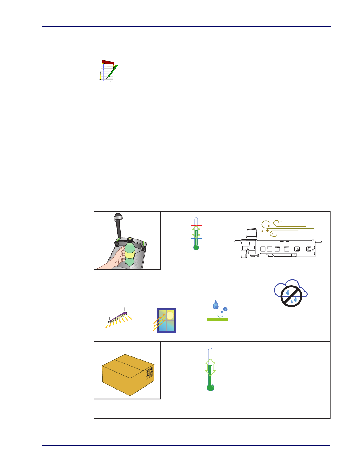
Warm-Up Time
There are two pertinent warm-up times that apply to the scanning-scale:
Thermal Equilibrium
When the unit is moved from a cooler temperature (such as a storage area) to a warmer
environment (such as a checkstand location), 60 minutes must be allowed to acclimate the unit
to ambient conditions prior to calibration or operation.
Power-up
Once installed and powered up, a warm-up time of 15 minutes must be allowed before
calibrating or performing weighing operations.
The two warm-up periods can be performed concurrently, thereby reducing the
total required warm-up time to 60 minutes.
NOTE
Figure 5. Environmental Specifications
Operation
Illumination
Artificial Light:
0-200 Foot-candles
(2,152 LUX)
Sunlight:
0-8,000 Foot-candles
(86,114 LUX)
+40° C +104° F
0° C 32° F
Temperature
+10° to +40° C
50° to +104° F
(Datalogic MS-0006-13-0004)
Storage
POS Scanner
Spill Proof
+70° C +158° F
-40° C -40° F
Dust Resistant Optics Cavity, IP5X
Humidity
Hot / Wet 40°C / 95% RH
Hot / Dry 40°C / 5% RH
Cold / Dry 10°C / 5% RH
Warm / Wet 25%C / 50% RH
Temperature
-40° to +70° C
-40° to +158° F
Product Reference Guide
9
Page 22

Introduction
Electrical Specifications
Before installation, always verify that the site’s electrical service meets the scanner’s
requirements. The scanner has been engineered for compatibility with most international
electrical systems operating in ranges from 100 to 240VAC at 50-60 Hz. Verify that the power
source will supply “clean” electrical power to the equipment; that is, it must be free of excess
electrical noise.
Power Supply
Check the IEC power cord shipped with the scannin
AC power receptacle, the power cord shipped is not compatible with your electrical system.
Please contact your distributor immediately to receive the necessary information and
components to ensure electrical compatibility.
The scanner utilizes a single power supply for all models. Unique installation and international
connections are accomplished through selection of the proper IEC power cord
VOLTAGE FREQUENCY CURRENT (RMS)
100-240VAC ±10% 50-60 Hz 0.5 Amps @ 100V
Safe operation of your scanner or scanning
trical outlets. Be sure to have a qualified elec
nection on circuits which will be used to power the unit.
CAUTION
The scanner is powered on/off by connecting/disconnecting its power supply.
NOTE
g-scale. If the cord will not plug into your
-scale requires properly grounded electrician certify the earth-ground con-
10
Magellan™ 9800i Scanner
Page 23
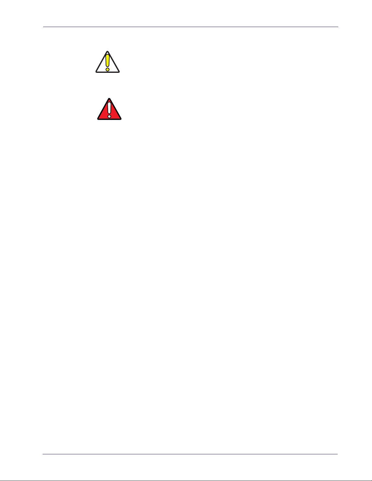
Safety Precautions
CAUTION
WAR NIN G
This Class A digital apparatus meets all requirements of the Canadian Interference-Causing
Equipment Regulations.
No adjustments or alteration of the scanner or scanning-scale housing
are to be attempted by the user.
This equipment has been tested and found to comply with the limits for
a Class A digital device, pursuant to part 15 of the FCC Rules. These limits are designed to provide reasonable protection against harmful interference when the equipment is operated in a commercial environment.
is equipment generates, uses, and can radiate radio frequency energy
Th
and, if not installed and used in accordance with the instruction manual,
may cause harmful interference to radio communications. Operation of
this equipment in a residential area is likely to cause harmful interference in which case the user will be required to correct the interference
s or her own expense.
at hi
Cet appareil numerique de la classe A respecte toute les
broilleur du Canada.
exigences du Reglement sur le material
Product Reference Guide
11
Page 24
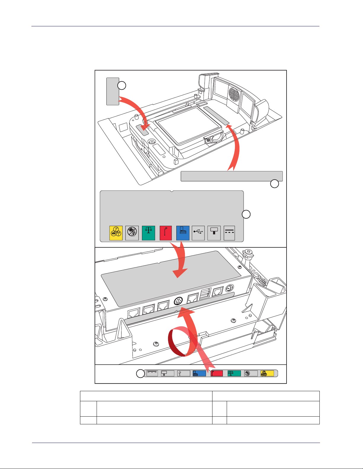
Introduction
Labeling
Regulatory, reference and safety labeling is shown in Figure 6.
Figure 6. Labeling
1
2
AUX
EAS
3
0.00
SCALE
HOST
4
POWER
HOST
TDR
PORT
0.00
REMOTE
USB
DISPLAY
USB
HOST
PORT
REMOTE
DISPLAY
TDR
POWER
SCALE
HOST
EAS AUX
12
Beneath the Platter Underside of Scanner
Scale Regulatory Label (units with scales
1
only)
2
Serial Number Label
3
Regulatory - I/F Label
4
Connector Bulkhead Label
Magellan™ 9800i Scanner
Page 25

Agency Compliances
The scanner and scanning-scale meets or exceeds the requirements for its device type as set forth
by the following agencies and regulations:
COUNTRY COMPLIANCE COMMENTS
Safety
United States UL60950-1 cULus Approved
Canada CAN/CSA C22.2 No. 60950-1 cULus Approved
Worl d IEC60950 CB certification
Korea KCC-Mark
EMC/EMI
United States FCC part 15 subpart J Class A
Australia/N Zealand AS/NZS CISPR 22 Class A
Canada ICES-003 Class A
Europe EN 55022 Class A
Japan VCCI 2011-4 Class A
ROW CISPR 22 Class A
Korea KN-22 KCC mark
Optical Emissions
Europe and ROW EN/IEC 62471 LED illumination
Weights & Measures (Scale units only)
United States
Canada Measurement Canada
Europe 2009/23/EEC EN45501
Australia
New Zealand 1999 Part 1 Regulations 5 and 6
Mexico NOM-010-SCFI-1994
Bureau International
de Métrologie Légale
(BIML)
NIST Handbook 44
(Dept. of Commerce)
National Measurement Institute (NMI)
OIML R76-1 and R76-2
certification
NCWM-NTEP
NMI R76, Parts 1 and 2
Class III scale,non-automatic
weighing
Product Reference Guide
13
Page 26

Introduction
COUNTRY COMPLIANCE COMMENTS
Power Supply
USA/Canada Safety cULusa
State of California CEC-400-2010-012 Energy Efficiency Standard
Canada NR Canada Energy Efficiency Standard
Europe CE and Level IV efficiency
ROW CB cert CB Safety Scheme
Mexico NOM and CONUEE Safety and Energy Efficiency
Japan PSE Safety J60950-1 and J55022
Russia GOST
Australia RCM and MEPS
Korea KCC and MEPS
Taiwan BSMI
China CCC Safety and EMC
Safety, EMC and energy efficiency Erp2009/125 EEC
Safety AS/NZS 60950-1 and
AS.NZS4665 (energy effi
ciency)
Safety, EMC and Energy Efficiency
Safety CNS 14336-1 and EMC
CNS 13438
-
Argentina IRAM S mark Safety
South Africa SABS Safety
Contact Datalogic ADC, Inc. or your Datalogic representative for a complete listing of
approvals for other countries.
14
Magellan™ 9800i Scanner
Page 27

Bar Codes Supported
The scanner can read/decode the following 1D and 2D bar code types (symbologies):
1D Symbologies
•UPC Versions A & E
• Plural Stage Dual UPC Bar Codes for Japan ( 2 label read)
• GSI DataBar Omnidirectional, DataBar Expanded, DataBar Stacked
• EAN-8 & 13
•JAN-8 & 13
• UCC/EAN 128
• GTIN Support
• Code 39
• Code 39 full ASCII
• Code 128 (including conversion to Code 39)
• Code 93
• Interleaved 2 of 5 (I 2 of 5)
• Industrial 2 of 5 (sometimes referred to as Standard 2 of 5)
• Code 32 (Italian Pharmaceutical Code)
• Codabar
•MSI
2D Symbologies
• PDF417, including driver’s license parsing
•MicroPDF
• Data Matrix
•Aztec
• QR Code
•Micro QR
Product Reference Guide
15
Page 28

Introduction
Technical Support
Datalogic Website Support
The Datalogic website (www.datalogic.com) is the complete source for technical support and
information for Datalogic products. The site offers product support, warranty information,
product manuals, product tech notes, software updates, demos, and instructions for returning
products for repair.
Reseller Technical Support
An excellent source for technical assistance and information is an authorized Datalogic reseller.
A reseller is acquainted with specific types of businesses, application software, and computer
systems and can provide individualized assistance.
Tel ephone Tec hnical Sup po r t
If you do not have internet or email access, you may contact Datalogic technical support at
(541) 349-8283 or check the back cover of your manual for more contact information.
16
Magellan™ 9800i Scanner
Page 29
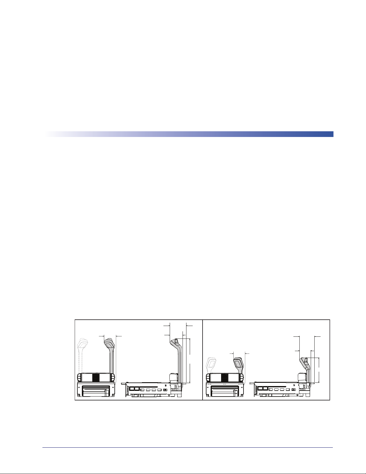
Chapter 2
8.3cm
(3.27”)
7.8cm
(3.07”)
Use same
dimension
for left side
mount
Tall TDR
Short TDR
12.7cm (5”)
Long Flange Mount
11.8cm (4.65”)
Long Flange Mount
8.3cm (3.27”)
Short & Medium
Shelf Mount
9.2cm (3.62”)
Short & Medium
Shelf Mount
31.45cm
(12.38”)
17.78cm
(7”)
Use same
dimension
for left side
mount
Site Preparation and Installation
This section provides instructions on preparation of the checkstand for scanner or scanningscale installation. It also specifies physical parameters, power and ventilation considerations,
cable routing information and unit installation.
The guidelines that follow, titled
Checkstand Preparation, present specifics for models
available at the time of this writing.
Some models are designed to fit with little or no modification into openings cut for previously
TM
installed
scanners such as other Magellan
Other models are designed for applications with smaller footprint requirements. See
scanners, or NCR® scanner models 7874/5/6/7/8.
Figure 8
for models available at the time of this printing.
Additionally, a Top Down Reader (TDR) module (
Figure 7) can be optionally included with a
scanner for installation. A TDR is purchased in one of two heights (tall or short) to allow
flexibility of installation.
Once the procedures in this section are complete, the scanner is ready for operation, excepting
if a scanning-scale was installed, calibration will be required before placing the unit into
that
operation. You must consult the local weights and measures authority to ensure that all legal
requirements are met concerning calibration and certification.
Procedures
, contains detailed procedures for calibrating the scale in either pounds or
Chapter 6. Calibration
kilograms.
Figure 7. Top Down Reader (TDR) Details
Product Reference Guide
17
Page 30
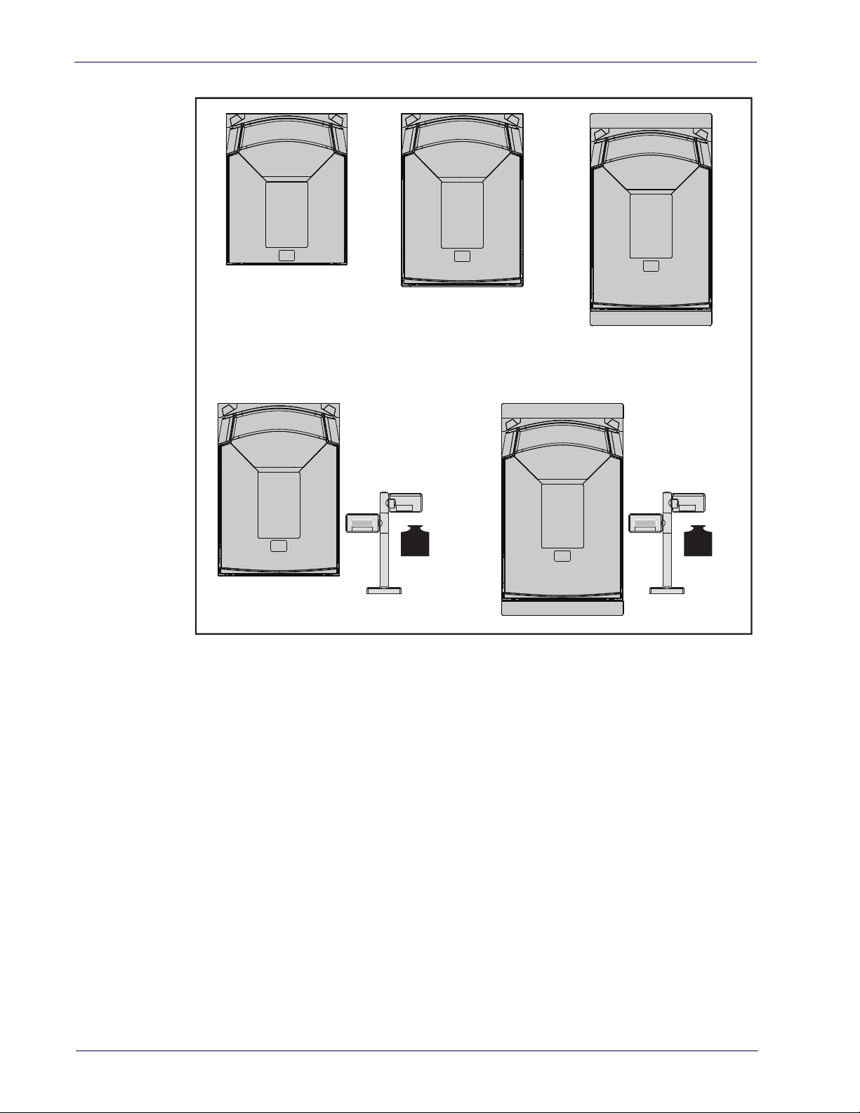
Site Preparation and Installation
Figure 8. Scanner and Scanner/Scale Models
Model 9801
Short Scanner
Model 9803
Medium Scanner
Model 9805
Long Scanner
Model 9804
Scanner/Scale
Installing the Optional TDR
Depending upon the model (see Figure 8), steps to install will vary slightly.
1. [Long Scanner/Scale models ONLY] After disconnecting power, remove the two bolts
secure the Back Flange Assembly (
that
assembly down and away from the unit. Set the assembly and its bolts aside for lat
stallation.
Medium
Model 9806
Long
Scanner/Scale
Figure 9, #1) to the Scanner/Scale, then slide the
er rein-
18
2. Determine the corner of the scanner where you desire the TDR to be installed. It must
eside in the left hand or right hand corner just behind the scanner’s bonnet. Carefully
r
push upwards on that plastic Corner Piece to disengage it from the scanner (
3. Gently slide the Filler Tab flatwise from the Corner Piece (
an opening which mates with the neck of the TDR.
4. Orient the TDR as shown (
5. Mate the Corner Piece with the TDR (
Figure 9, #4).
Figure 9, #5).
Figure 9, #3). This will leave
Magellan™ 9800i Scanner
Figure 9, #2).
Page 31

6. Route the TDR cable down through the base of the scanner (Figure 9, #6), gently pulling
1
2
5
6
8
7
9
3
4
it all the way through on the bulkhead side of
cavity. Make sure it is not pinched or caught beneath the scanner base.
7. Use a 3mm ball end hex driver to secure the TDR with the two bolts provided for this
purpose (
8. Fully seat the plastic Corner Piece in the grooves intended for it on the scanner frame
Figure 9, #8).
(
Figure 9, #7), tightening them evenly to 1.74Nm (15 in-lb).
the base and seating the TDR in its corner
9. Verify that the cable is not pinched or caught be
pin Din connection in the center of the bulkhead (
10. [Long Scanner/Scale models ONLY] S
the Scanner/Scale using the original bolts. Tig
Figure 9. Installing the Optional TDR
ecure the Back Flange Assembly (Figure 9, #1) to
tween assemblies, then connect it to its 8-
Figure 9, #9).
hten both evenly to 0.79 Nm (7 in-lb).
Product Reference Guide
19
Page 32

Site Preparation and Installation
Pre-Installation Considerations
This manual does not cover all factors relating to worker safety and checkstand design. It does,
however, offer a list of considerations that may be helpful in ensuring greater safety and
productivity. Careful planning using these general guidelines should result in a more efficient,
comfortable work environment.
The U.S. Bureau of Labor Statistics reports that the incidence of repetitive motion injuries has
increased dramatically in recent years. Checkstand design and scanner installation and operation
procedures can reduce the risk of repetitive motion injuries, but not eliminate it.
Although there are currently no formal guidelines for checkstand ergonomics, the Food
Marketing Institute (FMI), Occupational Safety and Health Administration (OSHA) and the
National Institute of Occupational Safety (NIOSH) of the Department of Health and Human
Services have released the reports listed at the end of these recommendations. These reports
contain useful suggestions for ergonomic improvement of checkstand designs and scanner
installation, maintenance and usage. Portions of the reports are summarized below. For copies
of the complete reports, or to inquire about any modifications to the recommendations, contact
FMI, OSHA and NIOSH at the addresses listed at the end of these recommendations.
20
Magellan™ 9800i Scanner
Page 33

Checkstand Design Recommendations
1. Select a design which allows load-sharing by several muscle groups (for example designs which allow the cashier to use both hands for scanning and bagging).
2. Use a powered in-feed conveyor to help cashiers bring the items to their best work zone, rather than leaning and reaching to get items further up the conveyor.
3. Select checkstands which deliver products to the cashier on an input belt and do not require the unloading of items from a cart. These designs put less stress on the cashiers’ shoulders and back.
4. Minimize the distance between the input and take-away conveyors (i.e., the distance the cashier has to reach to move the products).
5. Minimize the width of the input conveyor to reduce the cashier’s reach to items on the far side of the belt; use a diverter or “sweeper” to direct products closer to the cashier.
6. Select a design which encourages the cashier to slide products across the scanner rather than gripping and lifting. Make sure the horizontal surface of the scanner is flush with all surrounding surfaces.
7. Choose a design which integrates the scanner and scale to eliminate extended reaches and lifts during weighing tasks.
8. Place the conveyor belt electronic eye close to the scanner, but allow sufficient area between the eye to ensure the belt does not push items in to the scanning field.
9. Locate commonly used items such as the cash drawer and printer within easy horizontal reach.
10. Remove, round-off, or pad sharp or hard edges with which the cashier may come into contact.
11. Provide an easily accessible bag stand at a height 13 - 17 inches (33 - 43.2 cm) lower than the top surface of the checkstand to reduce stresses to the shoulders, elbows, and risks associated with lifting products into bags.
12. Do not position the bag stand between the cashier and the scanner, due to the increased reach involved.
13. Position the scanner’s horizontal scanning surface 34 - 36 inches (86.4 - 91.4 cm) above the floor. Maintain a minimum of five inches (12.7 cm) clearance between elbows and work surfaces.
14. Provide adjustable keyboard mounting (height, tilt, and horizontal reach).
15. Position the printer, cash drawer, and other checkstand devices the cashier uses within easy reach (less than 18 inches/45.7 cm).
16. Provide adequate toe space (at least four inches), foot rests or rails, antifatigue mats, and where feasible, an adjustable seat or stand against which the cashiers can lean.
Product Reference Guide
21
Page 34

Site Preparation and Installation
Scanner Installation
1. Mount the horizontal surface of the scanner flush with the countertop to encourage slide scanning rather than lifting.
2. Position the centerline of the scanner read area 8 - 10 inches (20.3 - 25.4 cm) from the edge of the checkstand (cashier side).
Scanner Maintenance
1. Keep scanner windows clean. This will improve productivity and reduce rescans.
2. Replace scanner glass when excessive scratches are evident.
References
U.S. Department of Labor
Guidelines for Retail Grocery Stores
www.osha.gov
Anonymous, 1992, “Ergonomic Improvement of Scanning Checkstand Designs”,
Food Marketing Institute
800 Connecticut Ave. N.W.
Washington, D.C. 20006
Grant, Katharyn A. et al., 1992, “Ergonomic Evaluation of Checkstand Designs in the Retail
Food Industry”,
National Institute of Occupational Safety and Health
4676 Columbia Parkway
Cincinnati, Ohio 45226
Scanner Usage
1. Minimize handling of heavy/bulky products. Leave these items in the cart and use an
alternative entry method such as key entry of short PLUs, LaneHawk
Basket) technology, or handheld scanning.
2. Regularly train cashiers in proper scanning methods and ergonomics principles, such as:
- Develop a smooth fluid motion during scanning, sharing work equally between hands.
- Use the entire hand for grasping and lifting items.
- Since the scanner reads labels on multiple sides, there should be no need to particularly
- Develop efficient scanning motions, not necessarily faster hand movements. Simply
- Leave items in an upright position; do not lift and tilt.
- Learn how the scanner functions and where the scanning area is located.
- Do not favor either the vertical or horizontal window; slide items across the scanner in
®
BOB (Bottom Of
orient a bar code toward the scanner windows.
slide the item across the scanner’s horizontal window with as little orientation motion as
necessary.
their natural orientations on the checkstand as much as possible.
22
Magellan™ 9800i Scanner
Page 35

Site Preparation Overview
Consider the following factors before installing the scanner/scanning-scale and its optional
Remote Scale Display.
Ventilation Requirements —
as there is adequate convective air flow and no major heat producing equipment in close
proximity, the unit’s housing provides adequate heat dissipation. The air temperature in the
checkstand around the scanner must not exceed 104°F (40°C).
Service Access Requirements —
require removal of the scanner from the checkstand or disassembly of the product. The installer
should plan service access for the AC/DC Power Supply and cables.
Recommended Power Installation —
belts and electric motors, care should be taken to ensure that the scanner has a supply of “clean”
power (power without excessive electrical noise).
Counter Preparation —
take away,” the counter drawings in this section focus on this counter design. Simply reverse the
layout for a “right-hand take away” requirement. The unit scans equally well in either of these
two configurations.
Liquid Drainage —
checkstand without pooling.
Leveling —
(board) to allow leveling of the scanner or scanning-scale within the counter. Use a 0.375” thick
board to replicate the mounting flange on the long scanner or scanning-scale, and adjust screws
or bolts until the board is flush within the counter. Use a 4.0” wide board stood on its end to
adjust leveling screws/bolts in rail support applications.
Plan ahead and provide screws/bolts in the checkstand mounts and a leveling guide
Should a liquid spill occur, ensure that moisture can flow through the
The scanner operates without the use of a ventilation fan. As long
Routine operations such as ‘zeroing’ and calibration do not
Since the typical grocery environment includes conveyor
Since the majority of grocery checkout lanes are designed as “left-hand
Cable Routing —
other components as well as optimize communication between the scanner, the POS terminal
and the optional Remote Scale Display. Note that cables may drop straight down from the
scanner’s connector panel, or may be conveniently routed along the unit’s side using the
hardware provided. Do not route interface cables near any electrical motors or other sources of
electromagnetic interference.
Remote Scale Display Placement —
to easily view and read the Remote Scale Display (if one is present). Ambient light and
mounting height considerations are discussed later in this section.
Vertical Clearance —
for removal and replacement of the All Weighs™ Platter (the L-shaped platter). Optimal
clearance permits the platter to be grasped at its top vertical edge and lifted for removal without
obstruction (such as a fixed keyboard mount or any type of enclosure). Should such an
enclosure be unavoidable, an alternate method of platter removal using two coins may be
employed, however a minimum vertical clearance of 1.5” (3.8 cm) MUST be provided
(reference
obstructions such as enclosures, keyboard mounts, etc.
Figure 10). Another consideration is that the scan zone must be kept free of
Placement of the scanning-scale should be planned to allow easy access to
The customer, and checker in some instances, must be able
Provision must be made to allow adequate space above the scanner bonnet
Product Reference Guide
23
Page 36

Site Preparation and Installation
DO NOT
Obstruct
Scan Zone
DO NOT
Obstruct
L-Platter
Removal
Allow a minimum
clearance of
1.5" (3.8cm)
(Enclosure)
(Keyboard Mount)
Figure 10. Vertical Clearance
24
Magellan™ 9800i Scanner
Page 37

Display Clearance —
D
I
S
P
L
A
Y
~30° minimum
6 cm
Clearance must be allowed so that a POS display will not interfere with
the scanner’s read zones. Adjustment must be made depending upon whether or not there is a
Top Down Reader (TDR) installed.
NO TDR —
POS display placement for scanners not having a TDR must not encroach the
scan zone formed by the horizontal and vertical windows. The bottom of the display must
be no lower than the 30° line shown in
Figure 11, which projects from the front edge of
the bonnet, 6 cm above the weigh platter.
With TDR — I
f a POS display is to be installed above the scanner in conjunction with an
installed TDR (long or short model), the face of the display can be no closer than 2 cm
behind the line shown in
Figure 12, which represents the frontmost edges of the scanner’s
bonnet.
Figure 11. Display Clearance With No TDR
Figure 12. Display Clearance With TDR
MUST be ≥ 2 cm behind this line
Face of Display
D
I
S
P
L
A
Y
2 cm
Product Reference Guide
25
Page 38

Site Preparation and Installation
Ventilation and Spacing
The scanning-scale’s perimeter housing has been designed to provide adequate space for
convective cooling and unrestricted movement of the weighing apparatus.
debris chutes and ventilation slots. The checkstand design must...
• keep the ambient air temperature inside the checkstand adjacent to the scanner below
1
04°F (40°C).
• allow a source of air that provides adequate coolin
DO NOT place the scanner in a close-fitting, fully enclosed checkstand. Provide a
MINIMUM of 16 square inches (103.2 square centimeters) of air intake from below
the installation for sufficient convective cooling.
NOTE
If motors, conveyor belts, or other heat producing equipment are located near the scanner,
forced air ventilation may be required. In most installations, a 30 cfm (.84 cmm) axial fan
should provide sufficient air movement. If a ventilation fan is installed, it is recommended to
use one with a removable filter that may be washed or replaced.
Figure 13. Debris Chutes & Ventilation Slots
Figure 13 shows the
g by convective air flow.
(Models vary)
Service Access
The scanner and scanning-scale have been engineered to allow performance of all routine service
and maintenance (such as “zeroing” and calibration) without removing the scanner from the
checkstand. Additionally all cable connections made at the scanner can be connected and
removed while the unit is sitting on the countertop. The installer should provide service access
to all remaining cable connectors as well as the AC/DC Power Supply (if installed).
26
Magellan™ 9800i Scanner
Page 39

Power Installation
Plug your scanner into an electrical outlet that has been wired to meet all applicable electrical
codes, laws, and regulations and has a common ground with the Point-of-Sale terminal.
Grounding
The AC/DC Power Supply should have an AC outlet with a clean earth ground. If you are not
sure how to verify the amount of electrical noise (interference) on the power line, ask a qualified
electrician to measure the input line voltage.
Checkstand Preparation
Reference Figure 14. When performing a first time installation into a new checkstand, verify
before cutting that room will be allowed for cabling
making the opening, take extra care to accurately cut to the correct dimensions. Mounting may
require installation of support(s), countertop routing, or other such devices. Depending upon
checkstand design, you may wish to install an item diverter to direct items toward the scan
window. See the instructions in this manual titled “Counter Cutout” for more details
concerning the location and preparation of the opening.
Figure 14. Installation Overview
and the AC/DC Power Supply. When
Cabling
(Models and
connections
vary)
AC/DC
Power
Supply
Support Rails
Counter Cutout
Item
Diverter
Routed
Support
Lip
Liquid Spills and Moisture
Select a checkstand design which allows fluids to flow through, and directs liquids away from
any electronic equipment or storage areas.
Product Reference Guide
27
Page 40

Site Preparation and Installation
Counter Cutout
The most important consideration when planning the counter opening for the scanner is the
operator’s comfortable reaching distance. The ideal, ergonomically sound installation allows
items to be directed within easy reach, and a scanning area requiring no lifting or special
orientation of items. If you haven’t already read the information at the beginning of this section
titled,
Pre-Installation Considerations, please do so before continuing these instructions.
The symmetrical design of the scanner permits the operator to easily pass items from one hand
to the other while scanning (either from right-to-left or left-to-right). With the unique multiside scan zone, scanning is accomplished in one fluid motion. The operator simply slides the
item from the conveyor belt or diverter area through the scanning area and passes the item to
the other hand, which in turn bags it or places it on a take-away conveyor belt. Movement
should flow naturally over the surface of the scanner.
Note that the following guidelines for preparing an existing checkstand to accept a scanner, or
incorporating the unit into a new checkstand design will not be accurate for all installations.
Although these guidelines will suffice for most standard installations, the installer may need to
make adjustments for varying counter heights and thicknesses, support design, or other
checkstand limitations.
Figure 15 shows a typical “left-hand-take-away” checkstand design.
Follow these basic steps to install the unit:
1. Select a position for the scanner that offers a smooth product flow which best accommodates the reaching distance of the average operator.
2. Cut the opening in the countertop. Select the appropriate drawing from Figure 17, or
Figure 20 for your model.
3. Install the AC/DC Power Supply, the Remote Scale Display cable and the interface cable(s) observing the following:
Interface cables (and display cable, if applicable) should be routed away from all
highly inductive electrical devices, like motors and conveyor belts, and even away
from the unit’s power cable if possible.
Cables should be easy to remove in the event that replacement is required. A little
planning now will save a lot of frustration later.
4. Connect and verify all system operations.
The scanner should be installed so that leading and trailing edges of the All Weighs™ Platter are
flush with the countertop to enhance smooth, slide-through scanning (reference
Keep in mind that the debris chutes on both sides of the platter provide the necessary clearance
for proper scale operation if you are installing a scanning-scale (you won’t need to provide an
additional gap for that).
Figure 16).
28
Magellan™ 9800i Scanner
Page 41

Figure 15. Typical Checkstand Design & Cutout Location
2
3
5
10
9
6
7
8
CAPACITY / CAPACITE - 30 X .01 lb / 15 x .005 kg
0.00
lb
1
4
1
Conveyor
2
Remote Display
3
POS Terminal and Printer
4
Keyboard
5
Scanner or Scanning-Scale
6
Top Down Reader (TDR) (optional)
7
Bagging Area
8
Bag Well
9
Check Writing Stand (optional)
10
Item Diverter (optional)
Product Reference Guide
29
Page 42

Site Preparation and Installation
Figure 16. Mounting the Scanner Flush
Scanner Mounted Flush — Correct
30
Scanner Mounted
Below Flush — Incorrect
Refer to the appropriate drawing for cut-out and dimensional information on the model you’ll
be installing:
Model Description
9801
9803
9804
9805
9806
Short Shelf Mount Scanner
Medium Shelf Mount Scanner
Medium Shelf Mount Scanningscale
Long Flange Mount Scanner
Long Flange Mount Scanning-Scale
Scanner Mounted
Above Flush — Incorrect
Cutout
Dime
nsions
Figure 17 Figure 18
Figure 19 Figure 20
Figure 19 Figure 20
Figure 21 Figure 22
Figure 21 Figure 22
Reference
Dimensions
Magellan™ 9800i Scanner
Page 43

Figure 17. Model 9801 (Short Scanner Model) Cutout Dimensions
Model 9801 (Short)
Minimum Cutout
Dimensions
Model 9801 (Short)
Supports
Max. Radius = 0.635cm
Support Rails
(0.25") 4x
Liquid
Drainage
35.6cm
(14.00")
min.
10.36cm (4.08")
29.53cm
(11.625")
min.
Liquid
Drainage
Figure 18. Model 9801 (Short Scanner Model) Reference Dimensions
9.46cm (3.72”)
Window
10.36cm (4.08”)
10.06cm (3.96”)
Model 9801
Reference
6.9cm (2.72”)
11.73cm (4.62”)
Dimensions
35.19cm (13.85”)
TDR adds 0.3 kg (0.75 lb)
29.21cm (11.5”)
6.7 kg
(14.75 lb)
Scanner Weight
(no scale)
Product Reference Guide
31
Page 44

Site Preparation and Installation
Figure 19. Models 9803 and 9804 (Medium Scanner or Scanning-Scale) Cutout Dimensions
Models 9803 and 9804 (Medium Shelf)
Minimum Cutout
Dimensions
Models 9803 and 9804 (Medium Shelf)
Supports
Max. Radius = 0.25"
(0.635cm) 4x
15.825"
(40.2cm)
min.
11.625"
(29.53cm)
min.
10.36cm (4.08")
Figure 20.
Model 9803
& Model 9804
Reference
Dimensions
Support Rails
Liquid
Drainage
Liquid
Drainage
Models 9803 and 9804 (Medium Scanner or Scanning-Scale) Reference Dimensions
Window
C
L
16.44cm (6.47”)
39.9cm (15.71”)
10.36cm
(4.08”)
29.21cm (11.5”)
8.6 kg
(19.0 lb)
Scanner/Scale
Weight
TDR adds 0.3 kg (0.75 lb)
6.8 kg
(15.0 lb)
Scanner
Weight (w/o scale)
6.9cm (2.72”)
10.06cm
(3.96”)
9.46cm
(3.72”)
32
Magellan™ 9800i Scanner
Page 45

Figure 21
. Models 9805 and 9806 Long Scanner or Scanning-Scale Reference Dimensions
Model 9805
& Model 9806
Max. Radius = 0.635cm
Cutout
If leveling feet are needed
for models 9805 and 9806,
use the placement shown here,
represented with plus signs (+).
Model 9805
& Model 9806
Supports
1.9 cm
(0.75")
1.9 ±0.15 cm
(0.75"± .060")
10.2 cm
(4.0")
(Center Line)
Rail
0.952 ±0.07 cm
(0.375" ± .030")
(0.25") 4x
1.905cm
(0.75")
Liquid
Drainage
51.12cm
(20.125")
47.308cm
(18.625")
51.2 ±0.15 cm
(20.125" ±0.06")
0.95 ± 0.08 cm (0.375" ± 0.03")
47.3 ±0.15 cm
(18.625" ± .060")
29.53cm
(11.625")
1.905cm
0.952 ±0.07 cm
(0.375" ± .030")
1.9 ±0.15 cm
(0.75"± .060")
(0.75")
Liquid
Drainage
Rail
7.77 ±0.15 cm
(3.06" ± .006")
7.77 ±0.15 cm
(3.06" ± .006")
3.8 cm
(1.5")
Figure 22. Models 9805 and 9806 Long Scanner
43.7cm (17.20”)
Window
34.9cm (13.74”)
23.74cm (9.35”)
6.9cm
(2.72”)
10.06cm
(3.96”)
9.1cm
(3.58”)
9.46cm
(3.72”)
34.9cm (13.74”)
Model 9805
& Model 9806
Reference
Dimensions
50.69cm (19.96”)
or Scanning-Scale Reference Dimensions
9.1cm
(3.58”)
10.36cm
(4.08”)
29.21cm
(11.5”)
8.7 kg
(19.25 lb)
Scanner/Scale
Weight
TDR adds 0.3 kg (0.75 lb)
6.9 kg
(15.25 lb)
Scanner
Weight (w/o scale)
Product Reference Guide
33
Page 46

Site Preparation and Installation
Checkstand Mounting
There are a number of things to take into account when installing the unit into a checkstand.
Key factors are ergonomic/worker safety, loading capacity and stability. Don’t forget to add the
scanner or scanning-scale’s weight when calculating materials and supports needed to construct
a sturdy installation, as well as maximum capacity of weighed and scanned items.
If you choose to rout a countertop with a thickness of 0.75” (1.9 cm) plywood,
you’ll need to add a backing strip that supports the area routed out for the support flanges (see
0.75” (1.9 cm) thick plywood and be approximately 4.0” (10.2 cm) wide and 14.0”
NOTE
(35.6 cm)
the countertop.
Installation Overview
The preceding Site Preparation Overview dealt with installed location and counter
preparations to accommodate the scanner or scanning-s
physical installation of the scanner or scanning-scale can begin. The following instructions
apply to all models.
Figure 14
long. This strip should be glued as well as screwed to the underside of
). This support strip should minimally be made of
cale. Having completed those steps,
This section describes:
1. Unpacking the unit.
2. Verifying operation before connecting to a POS system.
3. Routing and connecting cables.
4. Validating that your scanner communication parameters
requirements.
5. Confirming connection to the EAS system.
6. Functional testing to verify operation when connected to the
The following text describes each of these steps.
match the POS terminal’s system
POS system.
34
Magellan™ 9800i Scanner
Page 47

Unpacking
(Models vary)
Protective vinyl
MUST be
removed from the
platter before use.
If equipped with
scale...
scale spacer (below
platter) MUST be
removed before use.
To unpack the unit:
• Inspect the package for signs of damage that may hav
e occurred during shipping. If dam-
age is found, report it to your carrier immediately.
• Lift out the accessory box containing the AC/DC Power Supply, optional Remote Scale
D
isplay and cable (if present), and the Quick Reference Guide.
• Remove the Quick Reference Guide and familiarize yourself with the unit’s controls and
atures. Leave the guide at the checkstand when the installation is complete.
fe
• Remove the protective packing and carefully lift the unit from the carton.
Be sure to save
the box and all packing material. In the event of failure, the unit must be returned to the factory in
its original packaging
.
• Carefully lift off the All Weighs™ Platter as shown in Figure 33 and remove the protective
foam pieces securing the weigh mechanism.
For added protection during shipment, the All Weighs™ Platter is covered with a
tight-fitting layer of vinyl as shown in
REMOVED before placing the unit into service.
Set the platter back in place.
Figure 23
. This vinyl layer MUST BE
NOTE
Also, if the unit is equipped with a scale, the scale spac
be removed prior to use.
Figure 23. Remove Protective Vinyl
er (below the platter) must
Product Reference Guide
• Proceed to the Operational Verification instructions below.
35
Page 48

Site Preparation and Installation
Operational Verification
Follow these steps to ensure that your unit has arrived undamaged and is fully functional before
installing it in the counter and connecting it to your POS system.
1. If the unit is a scanning-scale, connect the R
on the unit’s connector panel (refer to
if the Remote Scale Display is not connected, a scanner power-up Selftest will
sound a long, low beep, and the number “8” will appear on the Health & Status
Figure 24
Chapter 7. Programming
NOTE
Indicator (see
a known-good Remote Display to the appropria
problem. Alternatively, you can disable the Remote Display using programming
bar codes (see
Figure 28).
) indicating a remote display error. Power-down, connect
Figure 24. Viewing the Health & Status Indicator
emote Scale Display to the proper connector
te port, and restart to correct this
, for more information).
36
2. Connect the power cable, first at the scanner, then at the AC outlet.
When power is applied to the unit, th
e normal indicator sequence is:
• The good read indicator LEDs will be lit (dim) steadily.
• [EAS models ONLY] The EAS
indicator LED will flash ON/OFF during power-up.
Magellan™ 9800i Scanner
Page 49

• Additionally, the Health & Status Indicator will flash the number ‘9’, indicating the EAS
system is being initialized.
If the Selftest detects a problem, the Health & Status Indicator will display a number code. Refer to
codes and problem isolation procedures.
Chapter 5. Problem Isolation
, for a description of failure
CAUTION
On rare occasions, performance of scale calibration may be necessary to obtain a
zero reading on the display.
NOTE
3. The unit should be permitted to reach thermal equilibrium before proceeding to the next
steps. (Reference the topic
Warm-Up Time in Chapter 1.) When the unit is moved from
a cooler temperature (such as a storage area) to a warmer environment (such as a checkstand location), a period of 60 minutes must be allo
wed to acclimate the unit to ambient
conditions. Once installed and powered up, a “power-up” warm-up period of 15 minutes
must be allowed before calibrating or performing weighing operations. These two warmup periods may run concurrently.
4. Verify that the scanner or scanning-scale passes an operational
test by observing the fol-
lowing:
Scanner —
Pass UPC/EAN bar code labels in front of the scanner’s windows. Since the interface
cable is not yet connected to the POS terminal, the scanner may be limited to reading
only one or two labels (see the note that follows). The scanner indicates when each label
has been successfully read by flashing the green scanner light and emitting a good read
tone (beep).
When not connected to the host, the scanner may be limited to reading only one
or two labels. (This limitation is dependent upon the interface type.) To scan multiple labels without connecting to the host, place the unit in Scanner Diagnostic
ode by pressing the Scanner Control Button for four seconds.
NOTE
EAS System —
M
The way in which EAS tags are deactivated is dependent upon the way the scanner is currently programmed with regard to EAS Mode. (See “EAS Mode” on page 42.) To
test EAS system function...
• Coupled Mode — Pass an item containing both a bar code and an active EAS tag over the
scann
er. Successful deactivation is indicated by the bottom-most LED flashing first red,
then orange, then returning to green. The beeper will sound a good read beep.
If you have enabled the manual deactivation function available for Coupled Mode (see
“Manual EAS Deactivation Push Button” on page -48), test the function by pressing the
bottom push button. A ticking sound will be hear
d which should cease upon deactivating
an EAS tag.
• Decoupled Mode — In this mode, items do not require a bar code to be scanned to arm
the deac
tivation function. Simply pass an active EAS tag over the scanner in the same
direction you would scan a bar code. The bottom-most LED will flash red to indicate
deactivation. No beep is sounded to indicate deactivation in this mode.
Product Reference Guide
37
Page 50

Site Preparation and Installation
• Hybrid Mode — In Hybrid Mode, the scanner must be enabled, however EAS deactivation in this mode also takes place without needing to scan an item’s bar code. Pass an
EAS tag over the scanner in the same direction you would scan a bar code. The bot-
active
tom-most LED will flash red, then orange, then return to green. The beeper may be configured to sound a high frequency beep to announc
e successful deactivation.
Scale —
tarily. If the scale is operating correctly, the yellow LED will illuminate and remain on
steady
is blank or a
tinuing. Refer to
calibration procedures.
Remote Scale Display —
place an item on the weighing platter. Verify that the display shows a weight and that the
yellow LED goes out. Remove the item and observe that Remote Scale Display shows
0.00 lb (0.000 kg for metric) and that the yellow LED is On.
5. Unplug the AC power cord from the outlet and disconnect the power cord and Remote
Scale D
After you have verified that the scanner and scal
continue with the following procedures to complete the installation.
Diagnostic Modes
Two diagnostic modes are available which allow you to initiate scanner or scale diagnostic tests,
as well as verify the scanner’s ability to read bar codes. Diagnostic messages will be displayed on
the Health & Status Indicator for both modes.
If the yellow scale indicator LED is not lit, press the Scale Zero Button momen-
, and the display will show a reading of 0.00 lb (0.000 kg for metric). If the display
- 0 -
is displayed, it may be necessary to calibrate the scale before con-
"Calibrating the Scale (Pounds & Kilograms)" starting on page 78, for
Check to verify that 0.00 lb (0.000 kg for metric) is displayed, then
isplay cable from the scanner’s connector panel.
e (if present) are completely functional,
Scanner Diagnostic Mode
While in Scanner Diagnostic Mode, continuous scanning of labels is allowed, permitting the
user to scan an unlimited number of bar codes while troubleshooting problems. Under normal
operation, the scanner stores label data, awaiting the signal which transmits it to the host. When
the scanner is not connected to a host, it may read and store only up to two labels, then quit
reading until power is cycled (clearing the memory). This mode of operation removes this
limitation.
To place the scanner in Scanner Diagnostic Mode, press
nine seconds. While pressing the button, the scanner will first sound three tones, wait a few
seconds, then sound six rapid tones; after which you should immediately release the button. For
more details about the Scanner Control Button and audio indications, see
Audio Indications & Controls
.
While in Scanner Diagnostic Mode, identification numbers for interface
configuration will scroll continually across the scanner’s Health & Status Indicator (Field
Replaceable
location of the display. For example, if the dual
Unit) display. This is useful information for field diagnostics. See
cable RS-232 interface (type 05) were enabled,
the firmware designation was R96-1234, and the configuration was R96-5593, the following
would be shown (slowly, with blanking between each of the items)
IF-05 r96-1234 r96-5593.
1. A listing of scanner interface identification numbers is available in Chapter 11, under the topic, Interface Type.
the Scanner Control Button for five to
Appendix A, LED/
1
type, firmware and
Figure 40 for the
38
Magellan™ 9800i Scanner
Page 51

To exit Scanner Diagnostic Mode, cycle power to the unit or press and hold the Scanner
x
x
Control Button for ten seconds to reset the scanner. See the topic,
Chapter 3 for more information about unit resets.
Scanner and Scale Reset in
Scale Diagnostic Mode
The scanner must be configured to allow Scale Diagnostic Mode. See the
gramming
section for details.
Pro-
NOTE
To enter Scale Diagnostic Mode, press the Scale Service Button (this is the same button as
ScaleSentry) for approximately four seconds. Six rapid tones will be sounded, indicating the unit
is leaving normal operation and entering Scale Diagnostic Mode.
Health & Status Scale Diagnostics
Upon entering Scale Diagnostics, the Health & Status indicator1 will then sound one medium
length beep and display a sequence of characters indicating the followin
Table 3. Scale Diagnostic Health & Status Indications
CHARACTERS
c x
x
- xxxx
Where x is the number of calibrations performed to the scale.
Where x indicates the number of times the scale has been zeroed.
Where x indicates the scale gravity zone.
Where xxxx is the load cell software checksum in hex lower 4 characters.
EXPLANATION OF INDICATION
g information:
- x
xxxx
zzzz zzzz
ucustomdata
Where x indicates the scale software revision.
Data area reserved.
Scale weighing package identifier and signal processing identifier if present.
Is the value of a custom data string (if present — no data may be displayed if
the item value is not set.
The sequence will be repeated
H
Upon successful completion, the scanner will automatically reset, displaying an H.
If the diagnostics routine is not completed successfully, the scanner will sound a series of tones
and the Health & Status indicator will show an error code. Turn to
Isolation
for a description of error codes.
Chapter 5, Problem
Press the Scale Zero Button once more to reset the unit and exit Scale Diagnostic Mode. See the
topic,
Scanner and Scale Reset in Chapter 3 for more information about unit resets.
1. The Remote Display (if one is present) can additionally display some scale diagnostic information.
Product Reference Guide
39
Page 52

Site Preparation and Installation
x
Optional Remote Display Scale Diagnostics Indications
If your unit is equipped with an optional Remote Display, it will show the following sequence,
with each character being separated by a500ms or greater blank time on the display (for ease of
reading). This display continues to scroll across the display until the scanner changes state or is
reset.
Table 4. Scale Diagnostic Remote Display Indications
CHARACTERS
EXPLANATION OF INDICATION
PASS or ERRx
c x
— x
xxxx
Cables & Connections
Considerations when routing the power and interface cables for the scanner and scanning-scale
are:
• Ensure that cables are not pinched, kinked or pierced.
• Do not route interface cables in close proximity
electromagnetic interference.
• Cables can drop directly from their connectors on the scanner
routed along the scanner’s side to the back (see
Where x is 1 through 5.
All segments on the display are illuminated.
Where x indicates the number of scale zeroing attempts.
Where xx represents the number of calibrations, with a maximum of 999
displayed.
Where x indicates the scale gravity zone.
Where xxxx is the load cell software checksum in hex lower 4 characters.
to electrical motors or other sources of
, or, alternatively, can be
Figure 25).
40
Do not plug the AC power cord into the outlet at
connect the power cable to the scanner first before plugging it into the AC receptacle. The
procedures titled, Set-Up, provided later in this section will instruct you to connect the power
cord at that time.
Figure 25 illustrates the basic cable routing scheme.
this time. It is a good practice to always
Magellan™ 9800i Scanner
Page 53

Figure 25. Cable Routing
Scanner
(Models vary)
AC Power
Switch
(recommended)
AC/DC
Power
Supply
EAS Controller Box
AC Power
EAS
Interface Cable
Scanner
Interface
Cable
Scale
Interface
Cable
(Scanner/Scale)
Optional
Remote Scale
Display Cable
(optional
Scanner/Scale)
POS Terminal, Printer &
Cash Drawer
Remote
Display
Keyboard
Top Down
Reader (TDR)
EAS Antenna Cable
Sensormatic EAS
Models ONLY
5.51"
(14 cm)
3.1"
(7.8 cm)
2.3"
(5.8 cm)
Figure 26 provides physical dimensions for the AC/DC Adapter (part number 8-0599).
Figure 26. Physical Measurements: AC/DC Adapter
Product Reference Guide
41
Page 54

Site Preparation and Installation
180°
Rotation
15°
Upward or
Downward Tilt
180°
Rotation
15° 15°
Dual Display
Heads
Single Display
Head
Remote Scale Display Placement/Installation
When installing the optional Remote Scale Display, consider both the customer’s viewing angle
and the amount of daily ambient light conditions anticipated at this installation site.
shows available adjustment for the display head.
Lighting Considerations
The display(s) will be easily readable unless placed in direct sunlight or other very strong light
sources. Light interference will not be a factor in most installations. For best viewing, the display
head(s) can each be rotated up to 180
Viewing Angle
The optimum display angle is directly facing the viewer. Tilt and rotation adjustments can be
made for the Remote Display models as shown in
readable for customers/cashiers of average height, display heads should
(122 to 152 cm) from the floor.
Check with local Weights and Measures authorities regarding proper
positioning of scale displays used in retail trade.
º
around the post and/or tilted 15º backward or forward.
Figure 27. To ensure that displays are easily
Figure 27
be between 48” to 60”
Figure 27. Modular/Adjustable Remote Scale Display
NOTE
42
Magellan™ 9800i Scanner
Page 55

Remote Display Cabling
18.5mm
28.4mm
Dual Display Single Display
329mm
325mm
292.5mm
227.5mm
116.39mm
112mm
60mm
264mm
116.39mm
112mm
60mm
25.5mm
85.1mm
41.99mm
Your installation should also take into account the routing of Remote Display cabling. Ensure
that distance and obstacles spanned by the routed cable will not kink, pinch or stretch it. Also
keep in mind you may need to drill a hole through which to route it.
The Remote Scale Display connector end may be secured with a rubber
band during shipping to prevent damage to the “locking tabs”. After
routing the cable, remove this rubber band before connecting. Failure to
NOTE
remove the band will keep the connector from latching properly.
Placing and Installing the Remote Display
Reference Figure 29 while performing these procedures.
1. Determine where you want to install the Remote Scale Display based on your counter
sign, the viewing angle, lighting considerations and cable routing discussed previously.
de
Reference
should be approximately eye level to the viewer(s).
Figure 28 for the display’s physical dimensions. Optimally, the display(s)
2. Use the template provided in
Figure 30 to mark locations of the mounting screw and
cable routing holes.
• The mounting screw holes are on 3-1/2” (85.1 mm) centers. The cable can either be
rout
ed through a
3
/4” (19 mm) diameter hole directly under the mounting base or
through the cutout in the back of the base (see
3. Drill the mounting screw holes using a drill
mounting screws or bolts.
3
4. Drill the cable routing hole using a
/4” (19 mm) drill bit (optional).
Figure 28. Remote Display Physical Measurements
Figure 29).
bit of the appropriate diameter for your
Product Reference Guide
43
Page 56

Site Preparation and Installation
48 - 60"
(122 - 152cm)
36"
(91cm)
11.5"
(29cm)
24"
(61cm)
Mounting
Example
(optional
cable
routing)
Dual Display
Heads
Single
Display
Head
5. Feed the entire length of the Remote Scale Display interface cable through the cable routing hole so that the assembled Remote Scale Display can be positioned over the mounting
ew holes.
scr
6. If present, remove the rubber band from the connector end.
7. Install mounting screws or bolts to complete the installation of the Remote Scale Display.
ake care not to pinch or pierce the interface cable while securing the Remote Scale Dis-
T
play to the checkstand.
Figure 29. Remote Scale Display Mounting
44
Figure 30. Remote Scale Display Mounting Template
116.39mm
41.99mm
85.1mm
25.5mm
Magellan™ 9800i Scanner
Page 57

Changing Weighing Modes
LEGAL NOTE
Your scanning-scale has been programmed for weighing in either pounds or kilograms
depending upon the initial operating environment that was specified when you ordered your
scanning-scale. If you need to change from pounds to kilograms or vice-versa, call
Support
You can verify that the scale is set correctly for your country’s requirements by observing that
the
power-up Selftest is completed.
.
Remote Scale Display shows the appropriate measurement symbol (lb or kg) when the
Set-Up & Installation
These setup and installation procedures assume that you have already prepared your checkstand
to receive the scanner or scanning-scale. If you have not already made the counter cutout and
routed power and interface cables, do so now as described in the previous instructions. If your
checkstand has been prepared, proceed as follows:
Technical
Any time the scale weighing mode is changed, the scale must be
re-calibrated before commercial use.
Set-up
1. Place the unit on the checkstand next to the counter cutout.
2. Route the cables up through the cutout and connect the scanner and scale interface
cable(s),
require two interface cables; one for the scanner interface and one for the scale interface.
Refer to
will vary depending upon the factory options purchased with your model.
If you have a scanner with no scale, there will be
3. Connect the power cord to the scanner and route the other end down through the check-
stand to the AC power outlet. DO NOT plug the power cord in at this time.
4. OPTIONAL — Route your EAS antenna cable down through the checkstand cutout.
Reference your EAS controller’s set-up instructions for proper EAS antenna installation.)
(
and Remote Scale Display cable (optional) to the scanner. Some POS terminals
Figure 31 for cable connection locations. The appearance of the connector panel
only one interface cable to the POS terminal.
Product Reference Guide
45
Page 58

Site Preparation and Installation
Figure 31. Connecting Cables to the Scanner/Scale
AC Brick Input
OR
Power off Terminal
(POT) Brick Input
Drives Remote Display · Label Data
Models with scale
only
0.00
Remote Display
Power POS TerminalUSB Port
Connector Bulkhead
USB PORTS
· USB Handheld
Scanner Input
· USB-to-Serial adapter
used for scale cali bration testing.
Connection to
these ports is
Optional
HOST PORTREMOTE DISPLAYPOWER
· Scale Data (for
single cable interfaces)
· Application Download
(where appropriate)
· Expands the scan
zone by scanning an
item’s fifth side.
· E-commerce bar code
reading.
· Captures photo
images.
Connection to
this port is
Optional
SCALE HOSTTOP DOWN READER
Scale Data (dual
cable scanner/scale)
Dual cable units only.
(Scale connection may
be handled through
POS Terminal port)
EAS
· Provides Good Read
output to enable EAS
antenna RF output
Connection to
this port is
Optional
Aux. PortEAS InterlockTDR Scale Host
AUXILIARY PORT
· Application Download
to attached RS-232
Handheld Scanner
Connection to
this port is
Optional
46
Magellan™ 9800i Scanner
Page 59

Figure 32. Optional EAS Cable Connections
To Checkpoint
®
EAS System
To Sensormatic
®
EAS System
5. Make sure that all cables are firmly attached (except that the AC/DC power supply should
not be connected to the AC outlet yet).
6. Remove the All Weighs™ Platter to gain access to the lift handles. Lift the top edge of the
platter
bezel as shown in
the platter is blocked, you may find it easier to grasp edges of the platter as shown by the
ows.
arr
Figure 33. Removing the All Weighs™ Platter
Figure 33 and gently lift it from the scanner. If the top edge of
7. The scanner provides lift handles that must be rotated up into position for use as shown
Figure 34. When released, these handles should be allowed to rotate back down into
in
their seated positions in the cavity. Use reasonable care when attempting to lift the unit
using any
Product Reference Guide
features other than the lift handles.
47
Page 60

Site Preparation and Installation
OK OK NO
Bubble Level
Figure 34. Using the Lift Handles
8. Lower the unit into the counter opening, ensuring that none of the cables are pinched, pierced or crimped.
1
9. View the bubble level (if present
scanner is level. As shown in the insert of
) located on the scanner's spider assembly to ensure the
Figure 33, the air bubble should appear fully
within the circle indicated. The air bubble can touch the circle, but must not overlap it.
A
pply shims beneath the scanner flange or adjust the leveling feet to allow level installa-
tion.
10. Reinstall the All Weighs™ Platter and verify that it is flush or just below flush with the
counter
top. This is necessary to provide smooth scanning from either direction. Make
adjustments as needed to align the platter with the counter by moving support rails up or
down, or consider installing screws in positions that will allow their use in adjusting the
unit’s position. Ensure that leveling is maintained if adjustments are made.
Failure to install a scanning-scale in a stable and level position will inhibit weighing, calibration and zeroing operations. The platter MUST make unobstructed
ontact with all of its supports for proper weighing operation.
c
NOTE
11. Once installation is complete, proceed with the Operational Verification procedures that follow.
48
1. The bubble level is present only on certain models.
Magellan™ 9800i Scanner
Page 61

System Power-Up Recap
The System Power-Up procedure may vary depending upon the requirements of your POS
system. It is generally a good practice to power-down (switch off) all equipment prior to
connecting cables. Check with your System Supervisor and/or refer to your POS terminal
manual for proper power-down and power-up procedures and interface requirements when
connecting any peripheral device.
If you have not identified any specific requirements for your POS system, follow these steps.
1. Power-down the POS terminal.
2. Ensure that power is disconnected from the scanner.
3. Connect the scanner and scale interface cables to your POS terminal. This connection
may use one or two cables depending upon your POS terminal interface.
4. Connect the Remote Display cable if your model is a scanning-scale and make any con-
nections to optional equipment, such as EAS1 or a handheld scanner.
5. Power-up the scanner or scanning-scale by connecting the power cord to an AC power
outlet. Wait for the unit to complete the Selftest routine (10 seconds maximum).
6. Power-up the POS terminal.
7. Verify that both scanning and weighing data are properly communicated between the
2
scanner and your POS system. (Weigh, deactivate
and scan a few items.) If problems are
encountered, refer to Chapter 4, Problem Isolation.
8. You have now completed installation and system integration of the scanner or scanning-
scale. At this point, the scale must be calibrated and certified in accordance with the
requirements of your state and/or local requirements. Refer to
Procedures for calibration details.
Chapter 6. Calibration
1. Some peripheral equipment must be connected or powered on in a specific order. Check the equipment instructions to verify the
correct sequence.
2. Test EAS deactivation only if applicable for your model.
Product Reference Guide
49
Page 62

Site Preparation and Installation
NOTES
50
Magellan™ 9800i Scanner
Page 63

The information contained in this section describes how to operate and maintain the scanner,
scale and EAS system. Topics include “how to’s” on scanning, EAS tag deactivation, weighing,
re-zeroing the scale, removing the top cover and cleaning the upper and lower windows.
Scanning Items
To scan items, slide or push them over the scanner as shown in Figure 35. Also see Figure 4 for
views showing the scan zone. The scanner will work equally well with either a left-to-right
right-to-left motion through the scan zone. There is no need to reorient an item’s bar code since
the scanner and its Top Down Reader (TDR) can read the left, right, front and back side, as
well as the top and bottom of an item.
NOTE
Chapter 3
Operation and Maintenance
or
“Limited Scanning Mode” is entered by default by interfaces such as USB and IBM
until a Point Of Sale (POS) terminal enables scanning. Labels are “chirped” while in
this mode.
Figure 35. Scanning an Item
Product Reference Guide
51
Page 64

Operation and Maintenance
Proper Scanning Technique
The scanner was designed to provide the ultimate in ergonomic enhancements for Point-OfSale (POS) scanning. To take advantage of these advancements:
Practice the techniques below to improve scanning efficiency:
• Move the product across the horizontal window (See
• Since the scanner reads labels on all four sides plus the top and bottom, don’t favor either
the horiz
• Remember to slide or push items rather than picking them up. By avoiding any gripping,
twistin
This technique also relieves you from lifting possibly thousands of pounds per day.
• Develop a smooth fluid motion during scanning, sharing
• Use the entire hand for grasping and lifting items.
• Develop efficient scanning motions, not necessarily faster hand
• Learn typical locations for bar codes on packages; avoid “flipping” or rotating the items
during scanning.
• Learn how the scanner functions and where the scanning area is located.
Figure 35).
ontal or vertical scan windows. Keep items in their natural orientation.
g and rotation of your hands and wrists, you can prevent repetitive motion injuries.
work equally between hands.
movements.
Proper Weighing Technique (Scale Models)
1. The L-shaped All-WeighsTM platter allows you to place items anywhere on its surface,
including leaning against its vertical section, to be weighed accurately. The raised lip on
the end also provides a convenient way to ensure items do not rest on the counter or
other non-weighing surfaces. (Reference
It is important that items rest entirely on the platter for their full weight to be
accurately recorded. An optional ScaleSentry
prevent the occurrence of item overlap onto non-weighing surfaces. See the fol-
NOTE
Figure 36. L-Shaped Platter, Item Placement
lowing section for more information about this feature.
and ScaleSentry
Figure 36a.)
TM
ScaleSentry
Beams
TM
feature can be employed to help
TM
52
ab
2. Once weighed items are in place, enter PLU (price Look-Up) data as described in your POS system instructions. Item weight is displayed on the Remote Display and/or the host display.
3. Remove the item from the weigh platter.
Magellan™ 9800i Scanner
Page 65

Using the Optional ScaleSentry
If the scanning-scale has been equipped with ScaleSentryTM, infrared (IR) beam(s) are emitted
along one or both long edges of the platter (See
being weighed, if an item approaches too close
surface, this is detected by the IR beam(s) and the scanner will indicate a ScaleSentry event by
illuminating its ScaleSentry indicator LED and/or sounding a special ScaleSentry tone. These
indications are configurable, and can be enabled or disabled using the
this manual.
TM
Feature
Figure 36b). During the process when items are
ly or extends past the edges of the weighing
Programming section of
Depending upon how ScaleSentry is configured, a scale transaction
1) The item(s) are physically repositioned to rest fully on the platter without overhanging the
side, or until 2) The ScaleSentry button is pushed, overriding the condition, or 3) It can also be
configured to only indicate the error, but still transmit the weight to the POS.
Deactivating Security Labels
Two different types of Electronic Article Surveillance (EAS) systems can be
optionally enabled for certain scanner models. Your system may or may not
be equipped with EAS deactivation functionality.
NOTE
Checkpoint
Checkpoint® systems require a wired connection as shown in Figure 2. When this system is
armed, Checkpoint EAS-tagged items are automatical
scanner’s platter area during scanning.
Sensormatic
Sensormatic® Ultra-Max®, Ultra-Strip® II and III EAS tags can be detected and deactivated by a
system that is equipped to do so. This is accomplished by means of a deactivation antenna
mounted under the scanner platter. EAS tags should be brought within five inches of the
antenna to be deactivated.
cannot be completed until:
ly deactivated as they are slid over the
EAS Deactivation Modes
Three modes of initiating deactivation are selectable via scanner programming (reference
Chapter 7, "EAS Mode" in this manual):
• Coupled Mode — Deactivation occurs only after item bar codes are read by the scanner.
• Decoupled Mode — Deactivation is independent of the scanning function
• Hybrid Mode — The EAS system is armed whenever the scanner is enabled and the deac-
tivation beep is sounded when an EAS tag is deactivated..
The EAS system must be functional to implement any of the EAS Modes. If
the EAS system is not active, error code 9 will be displayed in the Health &
NOTE
Status Indicator (see
Figure 43
).
EAS Deactivation Indicators
The scanner can be programmed to beep in acknowledgement of deactivation or upon
deactivation failure. Additionally, the tri-color indicator (the bottom-most LED) displays
Product Reference Guide
53
Page 66

Operation and Maintenance
deactivation status. (For more information about Beeper and LED indications, see the LED/
Beeper Indications & Controls section of this manual. Also ref
for their configurable featur
• Green means the system is ready (standing by).
• Red signifies the system has detected an EAS tag.
• Orange indicates an EAS tag is being deactivated.
Manual EAS Deactivation Push Button
The bottom-most push button is reserved for use in rare instances where EAS tagged items are
not automatically deactivated when brought through the scan zone. This button is not intended
for regular use. In instances where deactivation is not automatically triggered, hold the EAS tag
directly downstream from the horizontal window, and press and release the Manual EAS
Deactivation Push Button. This manual deactivation feature is optional, and can be enabled/
disabled via the bar codes located in the programming section of this manual.
erence the programming section
es.) By general default, LED indications are:
The item will be deactivated and a message to store managem
sent.
In a case where an item’s bar code is damaged or obscured by an EAS tag or
other obstruction, the operator will need to key enter the bar code number
and use the Manual EAS Deactivation Push Button to manually deactivate
NOTE
the EAS tag.
Deactivating the EAS System when failed
In cases of EAS system failure or malfunction, a scanner can be enabled to operate independent
of the EAS deactivation function. This is accomplished by pressing and holding the EAS
Manual Deactivation Push Button for three seconds. The scanner will sound three high-pitched
beeps upon bypassing the EAS function in this manner. When in this state, the scanner’s EAS
LED will flash slowly red, as well as the FRU Status LED, which will slowly flash error nine (9).
Operational Controls
The function of scanner and scale controls and indicators is listed in Appendix A, LED/Beeper
Indications & Controls. Turn to that appendix for full details.
ent that this has occurred will be
Operational Modes
The scanner or scanner/scale features a number of modes that are important to both the user
and the system support personnel. These modes can be combined into three groups: preoperational, operational, and additional functions. The following text describes these modes,
what they mean, and how and when they are seen.
Power-Up/Selftest & Pre-Operation
Pre-Operation describes those steps that must be successfully completed before the scanner
sounds the initial good read tone and illuminates the lamps indicating the scanner and/or scale
are ready for operation. These steps include Power-Up Selftest, Error Reporting, and
Operational Configuration.
54
Magellan™ 9800i Scanner
Page 67

NOTE
. lb
. kg
Power-Up/Selftest
Power-Up Selftest begins when power is applied. The scanner’s software immediately begins the
testing sequence to verify that all systems are functioning properly. This routine, which only
takes a few seconds, checks all the functions of the scanner, EAS deactivation system, scale,
remote scale display and interface prior to indicating that it is ready for operation.
A tone indicating Selftest is complete is a configurable feature. See the
Chapter 7, "Power-up Beep Control"
in this manual.
Error Reporting
If a fatal error is detected during Selftest or operation, the unit will not advance to Normal
Operation Mode. Selftest diagnostics will cause the unit to sound a long, low tone and/or
display an error message on the Health & Status Indicator indicating where the failure occurred.
These messages are coded to assist the repair technician in identifying the failed component. If
the error is with the EAS deactivation system, the bottom-most LED will flash red. If an error is
indicated, make note of it and contact your supervisor or technical support representative. A
table containing descriptions of these error codes is included in
If a non-fatal
long, low tone and display a number on the Health &
1
error is detected (such as a EAS deactivation system error), the unit will sound a
Status Indicator. The unit will advance to
Normal Operating Mode, but performance may be affected until a correction or repair is made.
Chapter 4, Problem Isolation.
Operational Configuration
Once Selftest diagnostics have been successfully run, a tone is emitted (if configured to do so,
and the unit enters an operational configuration state. The scanner or scanner/scale will
automatically load your specific interface settings which are required to communicate with the
host system. There are two conditions that must be met before the unit can enter Operating
Mode:
• No bar code label can be in the scan volume while the un
• If your scanner has a scale, the scale cannot be
• The scale must be able to “capture” zero weight. The display will be seen if
• When the scanner or scanner/scale completes its S
Operating Mode
it is in this state. Progress is
halted until the label has been removed, thereby ensuring that no extraneous bar code data
is sent to the host.
in motion (usually caused by excessive
vibration in the checkstand) for this test to succeed. A “Scale in Motion” status will be
indicated by displaying a period and the applicable weight unit (lb
kg
) that is selected.
or
there is a weight on the platter at power-up. Removing the weight or pressing the Sscale
ero Button should allow the scale to find zero.
Z
elftest successfully, it emits a tone (when
configured to do so) and enters Operating Mode.
Operating Mode includes Normal Operation (scanning, EAS deactivation and weighing) and
Sleep Mode. These two modes are most commonly observed by the user/operator.
1. Scanner behavior under non-fatal error conditions is configurable. See Chapter 7, Programming for more details.
Product Reference Guide
55
Page 68

Operation and Maintenance
Normal Operation
This condition is indicated by the scanner green LED and the EAS deactivation LED both
being on dim and steady. For scanner/scale models, the scale yellow LED indicates that the scale
senses a weight of zero on the platter. If you have a scanner without scale model, the yellow
lamp will not be lit when the scanner is ready for scanning.
Yellow and Green LED indications are configurable. Your scanner may not
be programmed to operate in the standard manner described above.
NOTE
Once the scanner enters Normal Operation, it begins a countdown sequence. If there is no
activity during a preset period of time (also called time-out
prolong the life of the electrical com
Mode.
Sleep Mode
After the scanner has been left idle for a preset period of time, the unit goes to sleep. This state is
called Sleep Mode, and is indicated by a “slow” blink of the green light (blinking at a 2-second
rate). To wake up the unit, press anywhere on the weigh platter (scanner/scale models only),
press the Volume Selection switch or wave your hand in front of the vertical window. The unit
will recognize any of these signals as a wake-up call and instantly return to Normal Operation.
Additional Functions
Additional scanner and scale functions include programming, running scanner or scale
diagnostics, initiating a reset, zeroing the scale, and calibrating the scale.
Programming
When your scanner or scanner/scale is shipped from the factory it is configured to work with the
POS system interface at your store and read the bar code symbologies you designated. If you
need to change this configuration information for any reason,
contains special bar code labels for changing the unit’s settings.
1
), the unit will shut off in order to
ponents. Once the scanner has timed out, it enters Sleep
Chapter 7, Programming,
Diagnostic Mode
Refer to Chapter 2, Diagnostic Modes, for details about running scanner and scale diagnostics.
Turn to
diagnostics.
Chapter 4, Problem Isolation, for a description of error codes resulting from
Scanner and Scale Reset
The reset procedures and indicators are identical for scanner and scanner/scale models. As with
any electronic equipment, it is sometimes necessary to reset the electronics. The reset procedure
allows you to initiate a reset command to the scanner. This may be necessary if the POS
1. “Timeout” and “Sleep Mode” time delays are programmable features that can be selected through use of the programming labels
included in
56
Chapter 7, Programming.
Magellan™ 9800i Scanner
Page 69

terminal has been switched off or the store system has been reset while the unit is on. Reset can
also be used to initiate and run the unit’s internal Selftest routine.
Pressing and holding the Scanner Control Button for ten seconds initiates a reset, which is
sounded by a rapid number of beeps. For more information, see the topic,
Pre-Operation earlier in this section.
Scale Adjustments
The scale allows two user adjustments: zeroing and calibration. The first, and most frequently
performed, is ‘zeroing’ the scale. This operation resets the scale’s “at rest” reading to zero which
must be within the range of - 0.2 pounds (- 1.25 grams) to +0.6 pounds (0.27kg) since the last
calibration. While the ‘at rest’ reading remains within the zero range, the scale will automatically
adjust itself to true zero. The scale also automatically zeros itself on power-up if the weight
present on the scale is within these defined limits.
Zeroing the Scale
The zeroing operation may be performed by checkers and other store personnel. Pressing and
releasing the Scale Zero Button should return the scale to Normal Operation. If the zero point
moves out of the zero range due to debris accumulation or other causes, pressing the Scale Zero
Button will not reset the zero point. In this case the weigh platter must be cleaned, debris chutes
cleared of debris or the scale must be recalibrated.
Power-Up/Selftest &
With the scanner/scale powered-up and at operating temperature:
1. Remove everything from the weighing surface of the scanner/scale.
2. Press the Scale Zero Button. (See Figure 58).
3. The Zero1 light will turn on and the display will show 0.00 lb (0.000 kg). If it does not,
see Chapter 4, Problem Isolation.
4. You have completed the scale zeroing function.
Alternatively, a reset (cycling power to the scanner) may also allow the scale to re-zero.
Calibrating the Scale
The second adjustment, calibration, defines and sets a standard reference weight range against
which all product weights are compared. If your scale is set for weighing in pounds, this range is
0 - 30 pounds, and, if your scale is set for weighing in kilograms, the range is 0 - 15 kilograms.
The scale must be calibrated upon initial installation, whenever the scale cannot be zeroed,
when the scale diagnostics indicate a calibration error, when the weighing measure (pounds or
kilograms) is changed, or when the scale module has been replaced.
Normally, once the scale has been calibrated, the calibration must be verified and/or approved
by a local regulatory body. In many areas, the scale calibration switch must be sealed before
being placed into service. Consult the agency responsible for regulating weighing devices in your
area to ensure that you are meeting all legal and regulatory requirements
"Calibration Procedures", describes the calibration sequence and verification process.
Chapter 6,
Calibration can only be performed if the tamper seal that secures access to the Calibration
Switch is broken and the switch cover is removed. Breaking the seal may legally render the scale
1. Zero light operation is configurable.
Product Reference Guide
57
Page 70

Operation and Maintenance
inoperable until it has been recertified and a new seal attached. Consult your local regulations
before removing the calibration seal if you are unsure of the legal requirements. Although the
scale will physically continue to weigh products, a broken seal may require recertification by a
proper authority as designated by your local laws.
Operational Maintenance
The scanner or scanner/scale will provide dependable service for many years. The following
maintenance procedures will keep your scanner or scanner/scale operating at peak performance.
Cleaning the Weigh Platter and Scan Windows
vertical scan windows at least twice daily with a nonabrasive, mild, water-based glass cleaner and
paper towels or lint-free cleaning tissues. The textured plastic surfaces and stainless steel can also
be cleaned using the same cleaning agents.
Cleaning the Air Gap/Debris Chutes & Drip Rail.
and the outer housing. Most items can be cleared from the debris chutes by carefully running a
thin stiff object like a credit card along all sides of the weighing surface. If necessary, remove the
platter to clear the debris chutes and drip rail.
Vertical Scan Window Replacement
The two Vertical Scan Windows enclosed in the All Weighs™ Platter are replaceable. Follow
these instructions to remove and replace a vertical window:
To remove a Vertical Scan Window:
1. Grasp the platter as shown in
edges can be grasped, and then lift straight up. If the top edge of the platter is blocked,
may find it easier to grip the edges of the platter as shown by the arrows.
you
Figure 37. Platter Removal
. Clean the exterior surfaces of the horizontal and
Daily, clear the debris chutes between the platter
Figure 37 and gently lift it from the scanner until the
58
2. The Vertical Scan Windows are held in place by the flat wedge-shaped plastic piece (#2 in
Figure 38) directly in front of them. To remove it, carefully release the six tabs on the
underside of the platter as shown in #1 of
and gently lift the plastic piece off of the platter.
Figure 38, then carefully turn the platter over
Magellan™ 9800i Scanner
Page 71

3. Either vertical window can be pressed out of its frame as shown in #3 of Figure 38. Care-
1
2
3
4
fully dispose of any damaged glass (#4 of
Figure 38).
Figure 38. Vertical Scan Window Removal/Replacement
1
Push in to release 6 tabs
Lift off the wedge-shaped plastic
2
piece
4. Carefully align the new vertical scan window it
3
Press window(s) in or out of the frame
4
Carefully dispose of the damaged glass
s window frame. Push in and upwards to
seat the window in the frame and secure it in place.
5. Reinstall the wedge-shaped plastic piece (#2 in
firmly over the entire surface to engage all six snaps and thr
Figure 38), pushing down gently but
ee detents along each side
where the plastic and stainless steel bezel are joined.
6. Clean both sides of the Vertical Scan Window using a paper towel or lint free cleaning tissues dampened with a mild, water-based glass cleaner
. DO NOT use abrasive cleaners or
pads.
7. Reinstall the platter. Vertical Scan Window replacement is now complete.
Product Reference Guide
59
Page 72

Operation and Maintenance
5
2
1
3
4
Horizontal Scan Window Replacement (DLC)
Diamond-Like Carbon coated (DLC) horizontal scan windows are replaceable. Use the
instructions below to remove and replace the window.
Sapphire glass does not require replacement, so it is permanently fastened in
place. Do not attempt to remove Sapphire glass from the platter.
NOTE
1. Remove the All Weighs™ Platter from the scanner as shown in Figure 37.
2. Turn the platter upside down on a
(#1 in
Figure 39). Retain all screws and nuts for later reinstallation.
3. Lift the edge of the retainer shown (#2 in
4. Take note of how the gasket is seated, then gently peel
the gasket (#3 in
5. The window (#4 in
Figure 39) for reinstallation.
Figure 39) can now be removed. Carefully dispose of any damaged
clean, dry surface and remove the two screws as shown
Figure 39) and remove it from the assembly.
it away from the assembly. Retain
glass.
6. While carefully holding it by its edges, orient the
“THIS SIDE UP” facing
down (the assembly is upside down at this point), then place the
new horizontal window with the words
window into position.
7. Fit the gasket into its channel and press around its entire perimeter to ensure it is fully
ted. Start by pressing in all four corners first.
sea
8. Secure the retainer using the original two screws.
9. Clean both sides of the new horizontal window using a paper towel or lint free cleaning
tissues dampened with a mild, water-bas
ed glass cleaner. DO NOT use abrasive cleaners
or pads.
Reinstall the platter. Gasketed horizontal window
(DLC) replacement is now complete.
Figure 39. Removing/Replacing the Gasketed DLC Window
1
2
3
60
Remove 2 screws
DLC Retainer
Gasket
4
DLC Window
5
All Weighs Platter (inverted view)
Magellan™ 9800i Scanner
Page 73

TDR, Camera and Mobile Commerce
The scanner can optionally include a Top Down Reader (TDR), Camera and/or a Mobile
Commerce Reader. These premium features offer state-of-the-art functionality to point of
sale transactions, while increasing first pass read rates for item scanning.
Optional TDR Feature
The Top Down Reader adds sixth side scanning to an already extensive scan zone (see
Figure 40a). Items being passed through the zone will be scanned from t
the front, back, two sides and bottom as shown in Figure 40b.
Figure 40. Top Down Reader (TDR)
ab
Chapter 4
he top as well as
Product Reference Guide
61
Page 74

TDR, Camera and Mobile Commerce
Yo u r
Coupon
Camera Feature
In addition to scanning bar codes, the TDR can optionally be used to photograph images
presented to the down-facing TDR window. The sales associate presses the scanner’s
Camera button to initiate Camera Mode and take pictures.
The way in which the TDR takes pictures in Camera Mode is a configurable feature.
See
Chapter 7, Programming
NOTE
Pictures can be optionally saved to a media card inserted in the scanner’s microSD card slot.
Mobile Commerce Reader
The Mobile Commerce Reader allows a customer to present digital coupons or other bar
codes from a cell phone or other device for convenient reading during checkout. The Mobile
Commerce Reader has different options for how it is enabled for reading items presented by
the customer. These are covered in more detail in the programming section, Top Down
Reader (TDR) and Mobile Commerce Imaging Features, starting on page 101
for more details.
.
Mobile Commerce options are also a configurable feature. See
gramming
NOTE
Figure 41. Scanning a Bar Code from a Cell Phone
for more details.
Chapter 7, Pro-
62
Magellan™ 9800i Scanner
Page 75

Chapter 5
Problem Isolation
The troubleshooting references provided in this section should be used in the event of a
suspected functional problem. This information will assist you in identifying and resolving
any problems.
The scanner/scale has a number of features that indicate when a scanner, EAS deactivation
system, or scale problem occurs. The unit may:
• emit a series of tones
• light the Health & Status Indicator (FRU status) display
• flash its indicator LEDs
• display error codes on the Remote Display (if installed)
Three error reporting modes are used: Power-Up Selftest, Operational tests and Diagnostic
tests. These test sequences are explained on the following pages.
Power-Up Selftest
The Power-up Selftest is a pre-operational series of tests that must be successfully
completed before the scanner indicates readiness for operation. This pre-operational period
is the time between power-up and normal operation during which the software, firmware
and hardware are being tested. These tests ensure that all subsystems are fully functional
before turning on. Refer to the
detailed description of this and other scanner and scale modes.
Section 3 subsection titled, Operational Modes for a more
Operational Tests
These are the tests that run continually during Normal Operation and Sleep Mode. Firmware
checks all subsystems, accessory connections and the POS interface to verify everything is
operating normally. If a problem is detected at any time, a long, low tone is sounded, an
error code is shown on the Health & Status Indicator, and operation may be halted. If you
press the Scanner Control Button at that time, a series of tones will be sounded that matches
the error code displayed.
Diagnostic Tests
See Chapter 2, Diagnostic Modes, for details about running diagnostic tests for the
scanner and/or scale. If a problem is discovered during diagnostics, the scanner will provide
feedback about the source of the problem. The remainder of this section describes these
failure indications and includes troubleshooting flowcharts to help isolate the problem.
Product Reference Guide
63
Page 76

Problem Isolation
Diagnostic Procedures
Your Point-Of-Sale (POS) system may contain many components that operate as a system.
Since almost all scanner or scale problems are caused by either the scanner, scale, POS
terminal or communication links between them, these troubleshooting flowcharts focus on
these components. Additionally, the optional Remote Scale Display, AC/DC Power Supply
and their cables are potential problems addressed in this section.
The flowcharts provided in this
isolate the failed component and instruct as to the corrective action required. Since internal
scanner and scale components cannot be replaced by an operator or installer, most functional
errors will require the assistance of a trained
problem is caused by faulty cable,
by replacing the defective component and complete the installation.
Error Codes
If an error is detected, the scanner will sound a low tone and the LEDs on the left control
panel will perform a “walking pattern” top to bottom indicating a failure. The Health &
Status Indicator (Figure 43) will display an error sequence as follows:
section walk you through a diagnostic process that will
Technical Support person. However, if the
power supply or remote display, you can fix the problem
1. An “equals” (=) sign always leads the sequence.
2. A (Field Replaceable Unit) FRU
indication code is displayed next. For two-digit num-
bers, there will be a blank in between each number.
3. Next, a dash (or hyphen) is displayed (-).
4. Finally, the indicator will display an (Event V
iewer) EVT code. This code provides
more advanced details about the failure for use by the repair technician. If you are
unable to resolve a problem, take note of the entire FRU Indication Sequence and be
prepared to communicate it to Technical Support when you make contact for assistance.
64
Figure 42. FRU Indication Sequence
Step 1 Step 2
Sequence
Start Symbol
(”Equals”)
Health and
Status Indicator
Step 3
FRU
Indication
(Varies)
or or
(Samples) (Samples)
Divider
Symbol
(”Hyphen”)
Step 4
EVT
Code
(Varies)
Magellan™ 9800i Scanner
Page 77

Table 6 describes what the FRU indication codes in step 2 mean, and what corrective action
might be taken for each.
Figure 43. Health & Status Indicator
Health &
Status
Indicator
When troubleshooting, always remember to check all cable connections first before proceeding with other problem isolation steps.
NOTE
Table 6. Error Code Table
Probable Cause Corrective Action
Make sure the correct interface is selected, then scan the factory defaults
Configuration Error
Host Interface
Main Board
Reserved
bar code and
about configuring the scanner using pr
Unplug unit and call technical support personnel.
reset the unit. Also, see Chapter 7, Programming, for details
ogramming bar codes.
See Chapter 7, Programming, for details about configuring the scanner
ScaleSentry Error
Interface Board Unplug unit and call technical support personnel.
for this optional feature, which may not have been purchased for your
scanner.
Product Reference Guide
65
Page 78

Problem Isolation
Health &
Status
Indicator
Probable Cause Corrective Action
Scale
Remote Display
Sensormatic Interface
Control Panel
USB Device
Scale Calibration Proceed to scale calibration procedure.
CPLD Call technical support personnel.
USB Host
See the topic Scale Error Reporting in this section for problem identification and corrective actions.
Connect the Remote Display. If necessary, replace display or cable. Alternatively, you can disable the Remote Display using the programming procedures described in Chapter 7, Programming.
No EAS communication. Check EAS cable c
EAS controller. Call technical support personnel.
Call technical support personnel.
Try resetting the scanner. If the problem persists
technical support personnel.
onnections and power to the
, unplug the unit and call
Scale Configuration
See the topic Scale Error Reporting in this section for problem identification and corrective actions.
66
Magellan™ 9800i Scanner
Page 79

Scale Error Reporting
Scale diagnostics uses the optional Remote Scale Display and the Zero Status lamp to
communicate specific scale failures.
The following chart shows the Remote Display messages, the Scale Status lamp indication,
the problem that the scale is experiencing and what action should be taken. When
troubleshooting, always remember to check all cable connections first before proceeding
with other problem isolation steps.
This does not apply to Adaptive Scale models.
Remote
lay
Disp
E _1
E__2
E__3
E__4
E__5
- 0 - Off
Scale Status
a
LED
Flash, pause, 1
bl
ink, long pause,
repeat sequence.
Flash, pause, 2
blinks
, long pause,
repeat sequence.
Flash, pause, 3
blinks
, long pause,
repeat sequence.
Flash, pause, 4
, long pause,
blinks
repeat sequence.
Flash, pause, 5
, long pause,
blinks
repeat sequence.
Problem
Description
Too much motion at
wer-up.
po
Calibration lost.
Scale communication
lost. Internal scanner/
scale problem.
Scale module failure.
Internal software fault.
Other Scale Reporting
Cannot zero at power-
weight remains
up or
on scale for more than 4
minutes or weight has
not returned to zero
between POS weight
b
requests
.
Action Required
Check for stable installation.
ange scale motion filter using
Ch
the labels found in the Program-
ming section; restart. If the prob-
lem persists, the scale may
equire calibration.
r
Call technical support personnel.
Re-calibrate; restart; recertify (if
required).
Call technical support personnel;
port error.
re
Call technical support personnel;
port error.
re
Call technical support personnel;
port error.
re
- Check debris chutes.
- Verify that the weigh platter
oves freely.
m
- Remove item(s) from scale
- Press Scale Zero Button
- for more information.
- If the scale still fails to zero, recalibrate the scale.
a. See , item #3.
b. This is a configurable feature.
Product Reference Guide
67
Page 80

Problem Isolation
START
YES
NO
Does
the scanner
power-up
?
YES
NO
Does
the scanner
pass Selftest
?
YES
NO
Are the
green indicator
LEDs lit
?
YES
NO
Are the
green indicator
LEDs lit
?
YESYES
NONO
Will the
scanner read
bar codes
reliably
?
YES
NO
Have you
checked the
power
connections
?
Check these
potential problems:
- AC power cord
- AC/DC adaptor
- AC outlet
Power-up
Scanner power-up is signified by any or
all of the following:
- Illumination LEDs turn on
- Status indicator LEDs turn on
- Speaker sounds tone(s)
- Remote display shows message
- A single red dot is visible on the 7 segment display
Selftest Failure
If the scanner fails its Selftest, the
following takes place:
- Speaker sounds a tone at the lowest
value for approx. 3 seconds.
- Green and Yellow LEDs flash on and off
alternately.
- 7-segment display shows a code (1 to
C) to indicate the failure.
Consult the Selftest flowchart if you're
unsure the unit has passed Selftest.
Flashing Green LED
If the green good read indicator LEDs
are flashing slowly, the scanner is most
likely in Sleep Mode. Press and release
the scanner control button or wave your
hand in front of the vertical window to
"wake-up" the scanner.
Flashing green LEDs can also mean the
scanner has been disabled by the POS
terminal. To exit this mode, cycle power
or have the terminal re-enable the
scanner.
For units using an AC/DC adapter, verify that...
1. AC power cord is connected to a functional AC outlet.
2. IEC connectors are firmly connected.
3. DC power cord is firmly connected to scanner.
If your unit is a model which receives Power Off the
Terminal (POT), verify that the I/F cable is securely
connected at both ends.
Magellan
Power
Supply
Go to Selftest
flowchart
Go to EAS
system flowchart
Go to Poor/No
Reading flowchart
YES
Does the
scale weigh
correctly
?
Does the
EAS Antenna
deactivate
tags
?
Go to Scale
flowchart
Ensure the green LEDs
are enabled via programming bar codes.
Call Tech Support
Other Problems?
Call Tech Support
(Models vary)
Flowcharts
The problem isolation flowcharts on the following pages allow you to identify and
troubleshoot problems with your system.
Figure 44. Problem Isolation: Start
68
Magellan™ 9800i Scanner
Page 81

Figure 45. Problem Isolation: Selftest
SELFTEST
START
Does the
Health & Status
Indicator show
YES
No interface selected
(Null Interface).
Select an interface.
Go to Scale
Error Reporting.
Health & Status
YES
Health & Status
0
?
Does the
Indicator
show 7.
?
NO
Does the
Indicator
show 8.
?
NO
NO
Does the
Health & Status
Indicator show
NO
Does the
Health & Status
Indicator show
2., 3., 4. or 6.
NO
Does the
Health & Status
Indicator
Check Remote Display
connection. Verify Remote
YES
Display configuration in the
Programming section. If
this fails, try connecting a
known-good display. Reset.
1.
?
?
show 5.
?
Scan the Factory
YES
Defaults bar code in
Section 6 to enable the
default configuration
file. Restart the unit.
YES
Call Tech Support
Check ScaleSentry
YESNO
feature configuration in
the Programming section.
Restart.
Health & Status
Indicator show
Does the
NO
Does the
Health & Status
Indicator show
1.
?
YES
NO
YES
TM
Does the
Health & Status
Indicator show
5.
?
NO
YES
8.
?
Does the
Health & Status
Indicator
show 9.
?
YES
NO
Calibrate the
Scale.
For this error, the Remote Display
may also show -0- or an error (E__#).
Unit passes Selftest
Check EAS
connections. Reset.
Does the
Health & Status
Indicator show
C.
?
Does the
Health & Status
Indicator show
d. or g.
?
Health & Status
Indicator show
Health & Status
Indicator show
A., b., E. or F.
Check TDR connections.
Verify configuration
YESNO
settings for the TDR and/
or the E-commerce
features.
Does the
9.
?
NO
Does the
?
YES
Call Tech Support
YESNOYES
Product Reference Guide
69
Page 82

Problem Isolation
Figure 46. Problem Isolation: Poor/No Reading
Have you verified that
all scan windows are clean
and scratch-free?
Enter Scanner Diagnostic Mode by
holding the Scanner Control Button
for five to nine seconds (until first 3,
and then 6 rapid tones are sounded),
then release. Scan a known-good bar
code.
A good read is
signified by one
flash of the Green
LED and a single
1
beep
.
POOR/NO READING
START
Does the
scanner read
the bar code
satisfactorily
?
YES
Reset the scanner by
holding down the Scanner
Control Button for 10
seconds.
NO
Before proceeding, verify that
bar code samples presented
to scanner are of good quality
and a symbology the scanner
is configured to read.
Call Tech Support
Scanner Diagnostics Mode can
be turned off by configuration.
Before proceeding, consult the
programming section of this
manual to make sure it is
enabled to be on.
If unexpected data
is being sent from
the host to the
scanner, consider
enabling the
programmable
feature Ignore Host
Commands to
debug the system.
Does the
scanner pass
the data to
the POS
?
NO
Go to No Transmit to
POS flowchart
YES
1
Does the
scanner read
satisfactorily
?
NO
Verify programmable
parameters using the
information and programming
bar codes provided in the
Programming Section. Check
bar code symbology options
and other configurable
features.
Green and Yellow LEDs and beeper indications are configurable
features. Behavior may vary from that described here.
YES
DONE
Does the
scanner read
satisfactorily
?
NO
Troubleshoot
the host or call
Tech Support.
YES
DONE
70
Magellan™ 9800i Scanner
Page 83

Figure 47. Problem Isolation: No Transmit to POS
NO TRANSMIT TO POS
START
Check the interface (I/F)
cable connections. If
possible, retest the
system using a
known-good I/F cable.
Does the
scanner pass
the data to
the POS
?
YES
DONE
Verify programmable
parameters using the
information and programming
bar codes provided in the
Programming Section. Check
interface and I/F options,
inactive symbologies and other
configurable features.
NO
Does the
scanner pass
the data to
the POS
?
NO
Troubleshoot
the host or call
Tech Support.
YES
DONE
Product Reference Guide
71
Page 84

Problem Isolation
Figure 48. Problem Isolation: Scale
SCALE START
View the Remote
Display and/or the
Yellow scale status LED
for the scale error code.
Reference the topic,
Scale Error Reporting in
this manual for more
information.
-0-
shown on
RemoteDisplay/
Yellow
LED off
NO
E__1
shown on
Remote Display/
Yellow LED
Flash once
NO
E__2
shown on
Remote Display/
Yellow LED
Flash twice
NO
E__3
shown on
RemoteDisplay/
Yellow LED Flash
3 times
NO
YES
?
YES
?
YES
?
?
For this error, the Health & Status
display may also show a 'C'.
YES
If this is a new installation,
make sure any foam packing
pieces have been removed
from the scale cavity before
proceeding. Lift off the platter
to verify, then set the platter
back into position.
DONE
- Check for debris under platter.
- Verify that the weigh platter
moves freely.
- Remove item(s) from scale.
- Press Scale Zero Button.
- Cycle power to the scanner.
- If the scale still fails to zero,
recalibrate the scale.
Problem is too much
motion at power-up.
Correct excess vibration
in counter if possible.
Problem is calibration lost.
Recalibrate the scale
using the calibration
procedures in this manual.
Problem is scale
communication lost.
Verify cable connections
to/from the scale.
YES
Is
problem
fixed
?
Increase the scale motion filter
setting by 1. Reference the
Programming Section for more
information.
NO
Is
problem
fixed
?
NO
Will the
scale
calibrate
?
Is
problem
fixed
?
NO
Call Tech Support
YES
NO
YES
Is the
motion filter
at its maximum
setting
?
NO
DONE
YES
DONE
YES
DONE
72
E__4 shown on Remote
Display/Yellow LED Flash
4 times. Problem is Scale
Load Cell failure.
Call Tech Support
Magellan™ 9800i Scanner
Page 85

Figure 49. Problem Isolation: Remote Display
REMOTE DISPLAY
START
Is the
unit configured
for a Remote
Display
?
YES
Verify that the Remote
Display cable is securely
attached to the external
Remote Display port and
reset the scanner.
Is the
problem
fixed
?
YES
Scanner-scale models that include
a Remote Display when shipped
from the factory, are configured
for use with the display. If you're
unsure of the settings for your
unit, contact Tech Support.
Use the programming bar
NO
codes in the Programming
Section to enable operation
using a Remote Display.
NO
Re-connect using a
NO
known-good Remote
Display. Reset the
scanner and retest.
Is the
problem
fixed
?
YES
DONE
Is the
problem
fixed
?
NO
YES
Replace the
Remote Display
DONE
Call Tech Support
Product Reference Guide
73
Page 86

Problem Isolation
Figure 50. Problem Isolation: EAS System
NO EAS DEACTIVATION
START
Check all EAS
cable connections.
Does the
EAS Antenna
deactivate
labels
?
YES
NO
DONE
Ensure operator has been trained in
proper EAS system use (reference the
topic “Deactivating Security Labels”).
Verify programmable
parameters using the
information and barcodes
provided in the Programming
Section. Check EAS options,
and other configurable features.
Does the
EAS Antenna
deactivate
labels
?
YES
DONE
If possible, retest the
NO
system substituting
known-good EAS cable
and/or controller box.
Does the
YES
EAS Antenna
deactivate
Call Tech Support.
labels
?
NO
74
Magellan™ 9800i Scanner
Page 87

NOTE
LEGAL NOTE
Chapter 6
Calibration Procedures
This section applies to scanner/scale models with single or dual interval.
Make sure to follow the proper associated procedure for each of these
single
options. Procedures specific to
salmon color
teal color
ina
. Procedures specific to
.
interval units is highlighted in a
dual
interval units is highlighted
These procedures are not applicable f
your adaptive scale documentation or the adaptive scale manufacturer for
more information.
A number of situations require the scale to be calibrated. They are:
• at initial installation of the scanner/scale
• if the scale cannot be rezeroed
• when changing the weight measure from pounds to kilogra
• if diagnostics indicate a calibration error
• when removing/replacing any scale assembly or the Main Board
• when required by local regulations
Follow the procedures on the following pages to ensure that the scanner/scale will meet
ts and Measurement requirements.
Weigh
Certification of the scanner/scale’s weighing apparatus is subject to Federal, State and Local Weights and Measures statutes and is restricted to
authorized go
Anytime a scale is calibrated, it should be properly sealed with a lead and
wire or paper seal before being placed into service.
It is your responsibility to check with the
area to ensure compliance with pertinent regulations before removing
any official seals or placing a newly calibrated scanner/scale into service.
vernment agencies and/or duly registered agents thereof.
or adaptive scale models. Consult
ms or vice-versa
appropriate authorities in your
Product Reference Guide
CAUTION
DO NOT apply a calibration seal to include the EAS antenna (if one is present).
Reference
would unnecessarily cause the scale to require recalibration.
Figure 52.
If the antenna must be removed for other reasons, this
75
Page 88

Calibration Procedures
Description of Calibration Sequence
The Calibration Sequence sets the scale to an accurate reference point for weighing. This
process involves the use of a Field Standard Weight Set (31.5-pounds) for calibration in
pounds, (18.5-kilograms) for Metric calibration. Once calibration has been successfully
completed, the scanner/scale uses the certified weight as a reference for subsequent
weighing activities.
These verification procedures follow the U.S. National Insti
tute of Standards and Technology 44
Handbook guidelines for bench/counter scale installations.
If any of these tests fail to meet the required weight indications, you must calibrate the
scan
ner/scale. Refer to the calibration procedures in this section for the proper
procedures.
You may be required by state and/or local regulations to have procedures other than these performed by
a certified technician or verification official.
Access to the calibration switch should be restricted with a paper or a wire and lead seal after
the calibration has been performed if required by your local regulatory agency.
The Calibration Sequence must be performed without removing the scanner/
scale from its installed position.
NOTE
The following tools and supplies will be required to perform the calibration process:
• 31.5 pound Field Standard Weight Set
1
.
(English calibration only).
2
• 18.5 kilogram Field Standard Weight Set
.
(Metric calibration only).
• Lead wire or paper seal (as required by law).
Motion Test
76
This test verifies that the scale will not ‘zero’ when the weighing surface of the scanner/scale
is in motion.
1. Verify that the Zero lamp is On and the Remote Display reads 0.00 pounds, 0.000
ounds or 0.000 kilograms.
p
2. Press lightly on the weigh platter of the scanne
r/scale with one hand and at the same
time press and release the Zero switch on the operator’s panel. The Zero lamp should
turn Off and the Remote Display should not display 0.00 pounds, 0.000 pounds or
0.000 kilograms.
3. Remove your hand from the weighing platform
and verify that the Zero lamp is On
and the Remote Display reads 0.00 pounds, 0.000 pounds or 0.000 kilograms.
1. NOTE: Throughout the calibration procedures, specified weights may be achieved by using a combination of weight from this set.
e.g. 20 lbs may be made up of one 10.00 lb. weight and two 5.00 lb. weights.
2. NOTE: Throughout the calibration procedures, specified weights may be achieved by using a combination of weights from thi s set.
e.g. 10 kgs. may be made up of one 5.00 kg. and five 1.00 kg. weights.
Magellan™ 9800i Scanner
Page 89

Automatic Zero Setting Test
.
lb
This test verifies that the scanner/scale automatic zero setting mechanism is operating
correctly.
SINGLE INTERVAL DUAL INTERVAL
Place 0.006 pounds (3 grams for metric) on the
center of the weighing platform. The entire
weight must be placed on the weighing platform
at once for this test to be valid. The Yellow LED
should go Off and the Remote Display should
read 0.01 pounds (0.005 kilograms).
The scanner/scale has an adaptive zero capture mechanism that re-zeros the
scale over time if there is a slow change in the zero level; thus, if all the weight is
not placed on the weighing surface at one time, the Zero lamp will remain On
and the Remote Display will read 0.00 pounds or 0.000 pounds (0.000 kilograms). When the weight is removed, the Z
NOTE
will show a minus sign
Place 0.0035 pounds (1.6 grams for metric) on the
center of the weighing platform. The entire weight
must be placed on the weighing platform at once
for this test to be valid. The Zero lamp should go
Off and the Remote Display should read 0.005
pounds (0.002 kilograms).
ero lamp will turn off and the display
. Press the Zero switch to rezero the scale.
Preparing the Scanner/Scale for Calibration
1. Assure that the scanner/scale is stable.
2. Power-up the scanner/scale.
3. Allow the unit to reach temperature equilibrium for at least one hour
scale is already at room temperature, allow at least 15 minutes to acclimate.
4. Remove all weight from the weighing surface a
in the debris chutes of the scanner/scale.
Do not pay attention to any message on the POS display.
NOTE
nd ensure that there are no obstructions
. If the scanner/
Product Reference Guide
77
Page 90

Calibration Procedures
Calibrating the Scale (Pounds & Kilograms)
1. Before proceeding, ensure that the scanner/scale has been prepared for this process by
performing the preceding steps titled,
2. Verify that there are no obstructions under the weigh platter. Remove the weigh platter
(L-Platter) and make sure that there are no obstructions in the debris chutes (see Figure
13).
3. If one is present, cut and remove the seal securing the calibration switch access cover. The seal may not be present if this is the initial installation of the scanner/scale.
4. Slide the cover to reveal the switch as shown in Figure 51.
5. Use a long, blunt object, such as the eraser end of a pencil to press and release the Calibration Switch and place the scanner/scale in Calibration Mode (see Figure 51c). The
scanner/scale will sound a tone indicating that it is in Calibration Mode. The Scale Status (yellow LED) will flash, indicating the scale is in Calibration Mode. If one is present, the Remote Display will show the message “ESCL” (empty scale).
6. Reinstall the weigh platter.
Preparing the Scanner/Scale for Calibration
7. Press the Scale Zero Button. The Scale Status (yellow LED) will go out for approximately 10 seconds (or less) and the Remote Display (if present) will alternately display
---- and ____ until the scale is ready to proceed.
8. When the scale is ready, the Scale Status (yellow LED) begins blinking again, and the
Remote Display (if present) will show the message “Ad20 (add twenty pounds)” or
“Ad10 (add ten kilograms).”
weighing in kilograms or two tones for pounds if you don’t have a Remote Display.
9. Place the correct weight (twenty pounds for calibration in pounds, or ten kilograms for metric calibration) from the Field Standard Weight set, onto the center of the weighing area. Press the Scale Zero Button again.
10. The Scale Status LED extinguishes for approximately 10 seconds and the Remote
Display (if present) alternately displays ---- and ____ until the scale is ready to proceed.
11. If the calibration was successful, the speaker sounds a single tone, the Scale Status LED begins blinking again, and “End-” appears in the Remote Display (if one is pres ent).
12. If the calibration was not successful, the speaker sounds five tones indicating a scale
failure, and the Scale Status LED will blink twice, strobe (fast blinks), and then contin
ually repeat this sequence until reset. Remove all weight from the Weigh Platter, and
repeat the procedure starting with step
The scanner/scale will also sound one tone if the scale is
8.
-
-
78
13. Press the Scale Zero Button again to permanently store the calibration data and exit
Calibration Mode. You have completed the calibration of the scale. The unit’s calibra
tion must now be verified as required by state and/or local weights and measures regulations. The verification procedure must be performed to assure that a scale will pass
Weights and Measures requirements before it is placed into commercial/retail service.
Magellan™ 9800i Scanner
-
Page 91

You have completed the scale calibration procedure. Before replacing the Calibration Switch
A
B
C
Cover and sealing the scale, you must now continue with the calibration verification tests
to complete the scale’s calibration. If you are weighing in pounds, continue with the
following procedures to verify that the scale was successfully calibrated and that it weighs
properly. If you are weighing in kilograms, turn to the instructions titled, "Calibration
Verification (Kilograms)" on page 85.
Figure 51. Calibration Cover and Switch Location
A
Calibration Seal Location
B
Calibration Access Cover
If an EAS antenna is present, it must be lifted in order to access the calibration
switch. See
Figure 52.
Calibration Switch Opening. Use a
C
long, blunt object to reach in and
press the Calibration Switch.
NOTE
Figure 52. If one is present, move EAS antenna to access the Calibration Switch
1
2
1
EAS Antenna
Product Reference Guide
2
Calibration Switch Cover
79
Page 92

Calibration Procedures
Calibration Verification (Pounds)
Once you have completed the calibration sequence, you may be required to perform these
step-by-step verification procedures. These procedures follow the National Institute of
Standards and Technology Handbook-44 guidelines for grocery scale installations. You may be
required by state or local law to have these procedures performed by a certified technician
or verified by a proper official.
These calibration verification procedures cover five (5)
• Increasing-Load Test
• Shift Test
• Blanking Test
• Decreasing-Load Test
• Return to Zero Test
If the scale fails any of the following tests, go to
follow the troubleshooting proc
NOTE
edures for SCALE FAILURE.
Increasing-Load Test (Phase 1)
This test checks Scale operation with two, four and six pound weights.
SINGLE INTERVAL DUAL INTERVAL
This test checks Scale operation with five, ten and
fifteen pound weights.
1. Check that the display reads 0.00 lb. when at rest with nothing on the weighing surface. (The Zero Status LED is steadily lit).
2. Place a five-pound weight on the center of the weighing surface and check that the display reads 5.00 lb.
3. Place an additional five pounds on the center of the weighing surface and check that the display reads between 9.99 and 10.01 lb.
4. Place an additional five pounds on the center of the weighing surface and check that the display reads between 14.99 and 15.01. Remove the weights and verify that the display reads 0.00.
5. You have completed the Increasing-Load Test (Phase 1).
different tests:
Section 4, Problem Isolation
This test checks Scale operation with two, four and
six pound weights.
1. Check that the display reads 0.00 lb. when at rest with nothing on the weighing surface. (The Zero Status LED is on steady).
2. Place a two-pound weight on the center of the
weighing surface. Verify that the Remote
Display reads 2.00 lb.
3. Place an additional two pounds (four pounds
total) on the center of the weighing surface. Verify
that the Remote Display reads between 3.995 and
4.005 lb.
4. Place an additional two pounds (six pounds total)
on the center of the weighing surface. Verify that
the Remote Display reads between 5.995 and
6.005. Remove the weights and verify that the
display reads 0.00.
5. You have completed the Increasing-Load Test
(Phase 1).
, of this manual and
80
Magellan™ 9800i Scanner
Page 93

Shift Test (6 Pounds Dual Interval ONLY)
(Models vary)
1
2
4
3
1
2
3
4
The Shift Test checks to ensure that items placed anywhere on the weighing surface of the
scanner/scale are weighed properly. Refer to Figure 53 when performing this test.
DUAL INTERVAL
1. Place and remove, in succession, a six-pound
load on the center of each of the four quadrants:
1, 2, 3, and 4, (as shown in Figure 53) of the
scanner/scale’s weigh platter. Verify that a reading of between 5.995 and 6.005 lb. registers,
r load, in each quadrant tested. Check that
unde
the display returns to 0.00 between each load.
2. After verifying the accuracy of each quadrant of
the weighing surface, remove all weight from
the scale. This completes the 6 pound Shift Test.
Figure 53. Shift Test
Product Reference Guide
81
Page 94

Calibration Procedures
Increasing- Load Test (Phase 2 Dual Interval)
NOTE
The upper limit of the scale is configurable according to the POS interface
type and may not necessarily be set at 30 pounds, which is the standard
setting. For this test, continue to place weights in two pound increments
only up to the upper weight limit set for your scale.
DUAL INTERVAL
After completing the Shift Test, you must complete
the Increasing Load Test using 8.0, 10.0 and 12.0
pounds of weight.
1. With the scale starting at zero, place 8.0 pounds in the center of the weighing surface and check that the display reads between 7.995 and 8.005 lb.
2. Place an additional two pounds (10 pounds
total) in the center of the weighing surface.
Check that the display reads between 9.995 and
10.005 lb.
3. Place an additional two pounds in the center of the weighing surface increasing the load to 12.0 pounds and check that the display reads between 11.995 and 12.005 lb.
4. Place an additional five pounds (fifteen pounds
total) on the center of the weighing surface. Verify that the Remote Display reads between
1
4.995 and 15.01. Remove the weights and ver-
ify that the display reads 0.00.
5. You have completed the Increasing-Load Test (Phase 2).
Shift Test (10 Pounds)
The Shift Test checks to ensure that items placed anywhere on the weighing surface of the
scanner/scale are weighed properly. Refer to Figure 53 when performing this test.
SINGLE INTERVAL DUAL INTERVAL
1. Place and remove in succession, a ten-pound
load on the center of each of the four quadrants
(1, 2, 3, and 4 in Figure 53) of the scanner/
scale’s weigh platter. Verify that a reading of
between 9.99 and 10.01 lb registers under load
and that the display returns to 0.00 between
each load.
2. After verifying the accuracy of each quadrant of the weighing surface, remove all weight from the scale. You have completed the Shift Test.
82
1. Place and remove, in succession, a ten-pound
load on the center of each of the four quadrants:
1, 2, 3, and 4, (as shown in Figure 53) of the
scanner/scale’s weigh platter. Verify that a reading of between 9.99 and 10.01 lb. registers,
under load, in each quadrant tested. Check that
the display returns to 0.00 between each load.
2. After verifying the accuracy of each quadrant of
the weighing surface, remove all weight from the
scale. This completes the Shift Test.
Magellan™ 9800i Scanner
Page 95

Increasing- Load Test (Single Interval Phase 2)
(Dual Interval Phase 3)
After completing the Shift Test, you must complete the Increasing Load Test using 20.0, 25.0
and 30.0 pounds of weight.
The upper limit of the scale is configurable according to the POS interface
type and may not necessarily be set at 30 pounds, which is the standard
setting. For this test, continue to place weights in five pound increments
NOTE
SINGLE INTERVAL DUAL INTERVAL
After completing the Shift Test, you must complete
the Increasing Load Test using 20.0, 25.0 and
30.0 pounds of weight.
1. With the scale starting at zero, place 20.0 pounds in the center of the weighing surface and check that the display reads between 19.99 and 20.01 lb.
2. Place an additional five pounds in the center of
the weighing surface, increasing the load to
25.0 pounds and check that the display reads
between 24.99 and 25.01 lb.
3. Place an additional five pounds in the center of the weighing surface increasing the load to 30.0 pounds and check that the display reads between 29.99 and 30.01 lb.
4. Remove the weights and verify that the display reads 0.00.
5. You have completed the Increasing-Load Test (Phase 2)
only up to the upper weight limit set for your scale.
After completing the Shift Test, you must complete
the Increasing Load Test using 8.0, 10.0 and 12.0
pounds of weight.
1. With the scale starting at zero, place 20.0
pounds in the center of the weighing surface and
check that the display reads between 19.99 and
20.01 lb.
2. Place an additional five pounds (25 pounds total)
in the center of the weighing surface. Check that
the display reads between 24.99 and 25.01 lb.
3. Place an additional five pounds in the center of
the weighing surface increasing the load to 30.0
pounds and check that the display reads between
29.99 and 30.01 lb.
4. Remove the weights and verify that the display
reads 0.00.
5. You have completed the Increasing-Load Test
(Phase 3).
Blanking Test
This test ensures that the scanner/scale will indicate its weighing capability has been exceeded
if a weight greater than 0.05 pounds over its maximum upper weight is placed upon the
unit.
1. Place weights that total the upper weight limit plus 0.051 pounds
example: If the upper limit is set at 30 pounds, place weights totaling 30.051 pounds
on the scale.
2. Verify that the display shows a dash and three hyphe
indication.
The scanner/scale may blank (show an underscore and three hyphens) at any
weight greater than its upper weight limit, but
weight limit plus 0.051 pounds are set upon the weighing surface.
NOTE
ns (_ - - -). This is the overweight
must blank when the upper
Product Reference Guide
on the scale. For
83
Page 96

Calibration Procedures
Decreasing-Load Test
This test ensures that the scanner/scale responds properly when a heavy object is followed by
a significantly smaller object.
If the upper weight limit for your scale is set to other than 30
pounds, begin by placing weight equaling your upper limit setting.
NOTE
SINGLE INTERVAL DUAL INTERVAL
1. Place a 30.0-pound load on the scale and verify that the display shows between 29.99 and 30.01 pounds.
2. Remove weights to leave 20 pounds on the
scale. Check that the display shows between
19.99 and 20.01.
3. Remove another 15.0 pounds from the scale and check that the scale reads 5.00 lb.
4. You have completed the Decreasing Load Test. 4. Remove 4.0 pounds and verify the display reads
1. Place a 30.0-pound load on the scale and verify that the display shows between 29.99 and 30.01 pounds.
2. Remove enough weights to leave 20 pounds on
the scale. Check that the display shows between
19.99 and 20.01.
3. Remove 8.0 pounds and verify the display reads
between 11.995 and 12.01 pounds.
between 7.995 and 8.005 pounds.
5. Remove another 6.0 pounds from the scale and
check that the scale reads 2 lbs.
6. You have completed the Decreasing Load Test.
Return to Zero Test
This test ensures that, after all other tests have been completed successfully, the scanner/scale
returns to zero. Remove all weights from the scale and verify that the scale reads 0.00 lb.
After completing this test, close the calibration access cover and seal per local Weights and
Measures requirements. This
state or local government.
You have completed the calibration and verification process for weighing in pounds.
If the scanner/scale passes all these tests:
1. Remove the weigh platter, inst
required).
2. Reinstall the weigh platter.
If the scale fails any of these tests, turn to Section 4, Problem Isolation and follow the
troubleshooting procedures for Scale Failures.
final step must agree with the legal requirements of your
all the calibration switch cover and install a seal (if
84
Magellan™ 9800i Scanner
Page 97

Calibration Verification (Kilograms)
Once you have completed the calibration sequence, you may be required to perform these
step-by-step verification procedures. These procedures follow the National Institute of
Standards and Technology Handbook-44 guidelines for grocery scale installations. You may be
required by state or local law to have these procedures performed by a certified technician
or verified by a proper official.
These calibration verification procedures cover five (5) different tests:
• Increasing-Load Test
• Shift Test
• Blanking Test
If the scale fails any of these tests, go to the topic Scale Error Reporting in
Section 4, Problem Isolation
NOTE
Increasing-Load Test (Phase 1)
SINGLE INTERVAL DUAL INTERVAL
This test checks Scale operation for increasing loads
from 0.100 kg and 7.50 kg.
1. Check that the display reads 0.000 kg when at rest with nothing on the weighing surface. (The Yellow LED is steadily lit).
2. Place a 100 gram weight on the center of the weighing surface and check that the display reads 0.100 kg.
3. Place an additional 200 grams on the center of the weighing surface and check that the display reads 0.300 kg.
4. Place an additional 200 grams on the center of the weighing surface and check that the display reads 0.500 kg.
5. Place an additional 100 grams on the center of the weighing surface and check that the display reads 0.600 kg.
6. Place an additional 100 grams on the center of the weighing surface and check that the display reads 0.700 kg.
7. Place an additional 100 grams on the center of the weighing surface and check that the display reads 0.800 kg.
8. Place an additional 200 grams on the center of the weighing surface and check that the display reads 1.000 kg.
9. Increase the weight on the scale to 7.50 kg on the center of the weighing surface and check that the display reads between 7.495 and 7.505 kg.
10. Remove the weights and verify that the display
reads 0.000 kg. You have completed the Increasing-Load Test (Phase 1).
· Decreasing-Load Test
· Return to Zero Text
This test checks scale operation for increasing loads
from 0.050 kg and 3 kg.
1. Check that the display reads 0.000 kg when at
2. Place a 50 gram weight on the center of the
weighing surface and check that the Remote
Display reads 50 grams.
3. Place an additional 100 grams on the center of the
weighing surface (.0300 kg. total) and check that
the Remote Display reads 150 grams.
4. Place an additional 100 grams on the center of the
weighing surface and check that the Remote
Display reads 250 grams.
5. Place an additional 50 grams on the center of the
weighing surface and check that the display reads
300 grams.
6. Place an additional 50 grams on the center of the
weighing surface and check that the display reads
350 grams.
7. Place an additional 50 grams on the center of the
weighing surface and check that the display reads
400 grams.
8. Place an additional 100 grams on the center of the
weighing surface and check that the display reads
500 grams.
9. Increase the weight on the center of the weighing
surface to 2.5 kg and check that the display reads
between 2.998 and 3.002 kg.
10. Remove the weights and verify that the display
reads 0.000 kg. You have completed the
Increasing-Load Test (Phase 1).
, of this manual.
rest with nothing on the weighing surface. (The
Zero Status LED is on steady).
Product Reference Guide
85
Page 98

Calibration Procedures
(Models vary)
2
1
3
5
4
23
45
1
Shift Test Metric (2 Kilogram Dual Interval ONLY)
The Shift Test checks to ensure that items placed anywhere on the weighing surface of the
Figure 54. Metric Shift Test
scanner/scale are weighed properly. Refer to Figure 54 when performing this test.
DUAL INTERVAL
1. Place and remove, in succession, a 2 kilogram
load on the center of each of the four quadrants:
2, 3, 4, and 5, and in the center (1) of the scanner/scale’s weighing platform (see Figure 54).
Verify that the Remote D
of between 1.998 and 2.002 kg for each quadrant/center test. Check that the display
0.000 between each load.
2. After verifying the accuracy of each quadrant and the center of the weighing surface, remove all weight from the scale. This completes the Shift Test Metric (2 Kilogram).
isplay shows a reading
returns to
86
Magellan™ 9800i Scanner
Page 99

NOTE
Increasing Load Test (Phase 2 Dual Interval ONLY)
After completing the Shift Test, you must complete the Increasing Load Test using 4, 5 and 6
kilograms of weight.
The upper limit of the scale is configurable according to POS interface type and may not
necessarily be set at 15 kilograms, which is the standard setting. For this test, continue to
place weights in 1 kilogram increments only to the upper weight limit set for your scale.
DUAL INTERVAL
1. Place 4 kilograms in the center of the weighing
surface and check that the Remote
Display reads between 3.998 kg and 4.002 kg.
2. Place an additional 1 kilogram in the center of
the weighing surface and check that the display
reads between 4.998 kg and 5.002 kg.
3. Place an additional 1 kilogram in the center of
the weighing surface and check that the display
reads between 5.998 kg and 6.005 kg.
4. Increase the weight on the center of the weigh-
ing surface to 7.50 kg and check that the display
reads b
5. Remove the weights and verify that the display
reads 0.000 kg. You have completed the
Increasing-Load Test.
etween 7.495 and 7.505 kg.
Shift Test — Metric (5 Kilograms)
The Shift Test checks to ensure that items placed anywhere on the weighing surface of the
scanner/scale are weighed properly. Refer to Figure 54 when performing this test.
SINGLE INTERVAL DUAL INTERVAL
1. Place and remove in succession, a 5.0 kilogram
load on the center of each of the four quadrants
(2, 3, 4, and 5 in Figure 54) and in the center (1)
of the scanner/scale’s weighing platform. Verify that the display shows a reading of between
4.995 and 5.005 kg for each quadrant/center
test and that the display returns to 0.000
between each load.
2. After verifying the accuracy of each quadrant and the center of the weighing surface, remove all weight from the scale. This completes the Shift Test — Metric (5 Kilograms).
1. Place and remove, in succession, a 5.0 kilogram
load on the center of each of the four quadrants:
2, 3, 4, and 5, and in the center (1) of the scanner/scale’s weighing platform (see Figure 54).
Verify that the Remote Di
of between 4.998 and 5.002 kg for each quadrant/center test. Check that the display returns to
0.000 between each load.
2. After verifying the accuracy of each quadrant and
the center of the weighing surface, remove all
weight from the scale. This completes the Shift
Test — Metric (5 Kilograms).
splay shows a reading
Product Reference Guide
87
Page 100

Calibration Procedures
Increasing- Load Test (Single Interval Phase 2)
(Dual Interval Phase 3)
The upper limit of the scale is configurable according to POS interface type and may not necessarily
be set at 15 kilograms, which is the standard setting. For this test, continue to place weights in 2.50
kilograms increments only to the upper weight limit set for your scale.
NOTE
SINGLE INTERVAL DUAL INTERVAL
After completing the Shift Test, you must complete
the Increasing Load Test using 10.00, 12.50 and
15 kilograms of weight.
1. Place 10.00 kilograms in the center of the weighing surface and check that the display reads between 9.990 kg and 10.010 kg.
2. Place an additional 2.50 kilograms in the center
of the weighing surface and check that the display reads between 12.490 kg and 12.510 kg.
3. Place an additional 2.50 kilograms in the center
of the weighing surface and check that the display reads between 14.990 kg and 15.010 kg.
4. Remove the weights and verify that the display reads 0.000 kg.
5. You have completed Phase 2 of the increasing load test.
After completing the Shift Test, you must complete
the Increasing Load Test using 10.00, 12.50 and
15 kilograms of weight.
1. Place 10.00 kilograms in the center of the
weighing surface and check that the Remote
Display reads between 9.990 kg and 10.010 kg.
2. Place an additional 2.50 kilograms in the center of
the weighing surface and check that the display
reads between 12.490 kg and 12.510 kg.
3. Place an additional 2.50 kilograms in the center of
the weighing surface and check that the display
reads between 14.990 kg and 15.010 kg.
4. Remove the weights and verify that the display
reads 0.000 kg.
5. You have completed Phase 3 of the Increasing
Load Test.
NOTE
Blanking Test
This test ensures that the scanner/scale will indicate its weighing capability has been exceeded
if a weight greater than 0.82 kilograms over its maximum upper weight limit is placed
upon the scale platter.
1. Place weights that total the upper limit plus 0.82 kilogra
example: If the upper limit is set at 15 kilograms, place weight totaling 15.82 kilograms.
2. Verify that the display shows a dash and three hyphens (_---). This is
indication.
The scanner/scale may blank (show an underscore and three hyphens) at any weight greater than its
upper limit plus 0.82 kilograms are set upon the weighing surface.
ms on the weigh platter. For
the overweight
88
Magellan™ 9800i Scanner
 Loading...