


 Loading...
MATRIX-2000™
Reference Manual

Datalogic Automation S.r.l. Via S. Vitalino 13
40012 - Lippo di Calderara di Reno Bologna - Italy
Matrix-2000™ Reference Manual
Ed.: 06/2008
ALL RIGHTS RESERVED
Datalogic reserves the right to make modifications and improvements without prior notification.
Datalogic shall not be liable for technical or editorial errors or omissions contained herein, nor for incidental or consequential damages resulting from the use of this material.
Product names mentioned herein are for identification purposes only and may be trademarks and or registered trademarks of their respective companies.
Datalogic is a registered trademark of Datalogic S.p.A. in many countries and the Datalogic logo is a trademark of Datalogic S.p.A.
© Datalogic Automation S.r.l. 2000 - 2008
24/06/08

CONTENTS
|
REFERENCES ............................................................................................................. |
v |
|
Conventions.................................................................................................................. |
v |
|
Reference Documentation ............................................................................................ |
v |
|
Service and Support ..................................................................................................... |
v |
|
Patents.......................................................................................................................... |
v |
|
COMPLIANCE............................................................................................................. |
vi |
|
EMC Compliance......................................................................................................... |
vi |
|
Power Supply............................................................................................................... |
vi |
|
LED Class.................................................................................................................... |
vi |
|
CE Compliance............................................................................................................ |
vi |
|
FCC Compliance ......................................................................................................... |
vi |
|
HANDLING................................................................................................................. |
vii |
|
GENERAL VIEW ......................................................................................................... |
ix |
1 |
RAPID CONFIGURATION ........................................................................................... |
1 |
|
Step 1 – Connecting the System .................................................................................. |
1 |
|
Step 2 – Mounting and Positioning the System ............................................................ |
5 |
|
Step 3 – Autolearning Configuration............................................................................. |
6 |
|
Step 4 – Installing VisiSet™ Configuration Program .................................................... |
9 |
|
Step 5 – Configuration Using Autolearning Wizard .................................................... |
10 |
|
Advanced Reader Configuration................................................................................. |
12 |
2 |
GENERAL FEATURES.............................................................................................. |
13 |
2.1 |
Introduction ................................................................................................................. |
13 |
2.2 |
Description.................................................................................................................. |
14 |
2.3 |
Model Description ....................................................................................................... |
16 |
2.4 |
Accessories ................................................................................................................ |
16 |
2.5 |
Application Examples ................................................................................................. |
17 |
2.6 |
External Lighting Systems .......................................................................................... |
20 |
3 |
INSTALLATION ......................................................................................................... |
24 |
3.1 |
Package Contents ...................................................................................................... |
24 |
3.2 |
Mechanical Dimensions.............................................................................................. |
25 |
3.2.1 |
Mounting Matrix-2000™ ............................................................................................. |
26 |
3.3 |
Positioning .................................................................................................................. |
27 |
4 |
CBX ELECTRICAL CONNECTIONS......................................................................... |
29 |
4.1 |
Power Supply.............................................................................................................. |
30 |
4.2 |
Main Serial Interface................................................................................................... |
30 |
4.2.1 |
RS232 Interface.......................................................................................................... |
31 |
4.2.2 |
RS485 Full-Duplex Interface....................................................................................... |
32 |
4.2.3 |
RS485 Half-Duplex Interface ...................................................................................... |
33 |
4.3 |
Auxiliary RS232 Interface ........................................................................................... |
35 |
4.4 |
Inputs .......................................................................................................................... |
36 |
4.5 |
Outputs ....................................................................................................................... |
39 |
4.6 |
External Lighting Systems .......................................................................................... |
41 |
4.7 |
User Interface - Host................................................................................................... |
42 |
5 |
MATRIX-2000™ CONNECTOR ELECTRICAL CONNECTIONS.............................. |
43 |
|
|
iii |

5.1 |
DB25-Pin Connector................................................................................................... |
43 |
5.2 |
DB9-Pin Connector (RS232 Auxiliary Port) ................................................................ |
44 |
5.3 |
RJ45 8-Pin Connector (Ethernet) ............................................................................... |
44 |
5.4 |
Power Supply.............................................................................................................. |
45 |
5.5 |
Main Serial Interface................................................................................................... |
45 |
5.5.1 |
RS232 Interface.......................................................................................................... |
45 |
5.5.2 |
RS485 Full-Duplex Interface....................................................................................... |
47 |
5.5.3 |
RS485 Half-Duplex Interface ...................................................................................... |
48 |
5.6 |
Auxiliary RS232 Interface ........................................................................................... |
50 |
5.7 |
Ethernet Interface (Matrix-21XX models only)............................................................ |
51 |
5.8 |
Inputs .......................................................................................................................... |
52 |
5.9 |
Outputs ....................................................................................................................... |
55 |
5.10 |
User Interface ............................................................................................................. |
57 |
6 |
TYPICAL LAYOUTS .................................................................................................. |
58 |
6.1 |
Point-to-Point .............................................................................................................. |
58 |
6.2 |
Pass-Through ............................................................................................................. |
59 |
6.3 |
RS232 Master/Slave................................................................................................... |
60 |
6.4 |
Multiplexer .................................................................................................................. |
61 |
6.5 |
Ethernet Connection (Matrix-21XX models only)........................................................ |
62 |
7 |
READING FEATURES............................................................................................... |
64 |
7.1 |
Reading Distance and FOV ........................................................................................ |
64 |
7.2 |
Maximum Line Speed Calculation .............................................................................. |
66 |
8 |
SOFTWARE CONFIGURATION................................................................................ |
68 |
8.1 |
VisiSet™ System Requirements................................................................................. |
68 |
8.2 |
Installing VisiSet™...................................................................................................... |
68 |
8.3 |
Startup ........................................................................................................................ |
69 |
8.3.1 |
VisiSet™ Options........................................................................................................ |
70 |
8.4 |
Configuration .............................................................................................................. |
72 |
8.4.1 |
Edit Reader Parameters ............................................................................................. |
73 |
8.4.2 |
Send Configuration Options........................................................................................ |
75 |
8.4.3 |
Calibration................................................................................................................... |
78 |
8.4.4 |
Multi Image Acquisition Settings................................................................................. |
82 |
8.4.5 |
Run Time Self Tuning (RTST) .................................................................................... |
82 |
8.4.6 |
Region Of Interest Windowing .................................................................................... |
83 |
8.4.7 |
Direct Part Marking Applications................................................................................. |
84 |
8.5 |
Image Capture and Decoding..................................................................................... |
86 |
8.6 |
Statistics ..................................................................................................................... |
86 |
9 |
MAINTENANCE ......................................................................................................... |
87 |
9.1 |
Cleaning...................................................................................................................... |
87 |
10 |
TROUBLESHOOTING ............................................................................................... |
88 |
10.1 |
General Guidelines ..................................................................................................... |
88 |
11 |
TECHNICAL FEATURES........................................................................................... |
91 |
|
GLOSSARY................................................................................................................ |
93 |
|
INDEX......................................................................................................................... |
96 |
iv

REFERENCES
CONVENTIONS
This manual uses the following conventions:
"User" refers to anyone using a Matrix-2000™ reader. "Reader" refers to the Matrix-2000™ reader.
"You" refers to the System Administrator or Technical Support person using this manual to install, configure, operate, maintain or troubleshoot a Matrix-2000™ reader.
REFERENCE DOCUMENTATION
For further details refer to: the VisiSet™ Help On Line, Matrix Reading Methods, Matrix Host Mode Programming, Matrix SW Parameter Guide, Matrix Symbol Verifier Solution provided as supplementary documentation on CD-ROM.
SERVICE AND SUPPORT
Datalogic provides several services as well as technical support through its website. Log on to www.automation.datalogic.com and click on the links indicated for further information including:
•PRODUCTS
Search through the links to arrive at your product page where you can download specific
Manuals and Software & Utilities
-VisiSet™ a utility program, which allows device configuration using a PC. It provides RS232 and Ethernet interface configuration.
•SERVICES & SUPPORT
-Datalogic Services - Warranty Extensions and Maintenance Agreements
-Authorised Repair Centres
•CONTACT US
E-mail form and listing of Datalogic Subsidiaries
PATENTS
This product is covered by one or more of the following patents:
U.S. patents: 6,512,218 B1; 6,616,039 B1; 7,102,116 B2; 7,282,688 B2 European patents: 999,514 B1; 1,014,292 B1.
Additional patents pending.
v

COMPLIANCE
For installation, use and maintenance it is not necessary to open the reader.
EMC COMPLIANCE
In order to meet the EMC requirements:
•connect reader chassis to the plant earth ground by means of a flat copper braid shorter than 100 mm;
•connect the main interface cable shield to pin 1 of the reader 25-pin connector;
•use two clip-on ferrite sleeves (type Stewart 28A2029-0A0) on the main interface cable near the reader 25-pin connector;
•connect the Ethernet interface cable shield to the reader chassis (for Matrix-21XX only).
POWER SUPPLY
ATTENTION: READ THIS INFORMATION BEFORE INSTALLING THE PRODUCT
This product is intended to be installed by Qualified Personnel only.
This product is intended to be connected to a UL Listed Computer which supplies power directly to the reader or a UL Listed Direct Plug-in Power Unit marked LPS or “Class 2”, rated 10 to 30 V, minimum 1 A.
LED CLASS
Class 1 LED Product to EN60825-1:2001
CE COMPLIANCE
Warning: This is a Class A product. In a domestic environment this product may cause radio interference in which case the user may be required to take adequate measures.
FCC COMPLIANCE
Modifications or changes to this equipment without the expressed written approval of Datalogic could void the authority to use the equipment.
This device complies with PART 15 of the FCC Rules. Operation is subject to the following two conditions: (1) This device may not cause harmful interference, and (2) this device must accept any interference received, including interference which may cause undesired operation.
This equipment has been tested and found to comply with the limits for a Class A digital device, pursuant to part 15 of the FCC Rules. These limits are designed to provide reasonable protection against harmful interference when the equipment is operated in a commercial environment. This equipment generates, uses, and can radiate radio frequency energy and, if not installed and used in accordance with the instruction manual, may cause harmful interference to radio communications. Operation of this equipment in a residential area is likely to cause harmful interference in which case the user will be required to correct the interference at his own expense.
vi

HANDLING
The Matrix-2000™ is designed to be used in an industrial environment and is built to withstand vibration and shock when correctly installed, however it is also a precision product and therefore before and during installation it must be handled correctly to avoid damage.
•avoid that the readers are dropped (exceeding shock limits).
•do not fine tune the positioning by striking the reader or bracket.
vii

•do not weld the reader into position which can cause electrostatic, heat or reading window damage.
•do not spray paint near the reader which can cause reading window damage.
viii
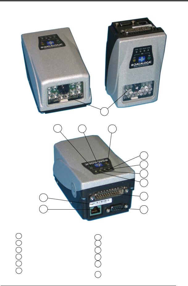
GENERAL VIEW
Matrix-2000™
1
2 |
3 |
4 |
|
|
|
5 |
|
|
|
|
6 |
|
|
|
|
7 |
|
|
|
|
8 |
|
|
12 |
|
9 |
|
|
11 |
|
10 |
|
|
|
Figure A |
|
|
1 |
Reading Window |
7 |
Good Read LED |
|
2 |
F2 LED |
8 |
Communication LED |
|
3 |
Keypad button |
9 |
Main/Auxiliary Interface |
|
4 |
F1 LED |
10 |
Auxiliary Interface |
|
5 |
Power On LED |
11 |
Ethernet Interface |
|
6 |
External Trigger LED |
|
(for 21XX models only) |
|
12 |
Ethernet MAC Address |
|||
|
|
ix

x
RAPID CONFIGURATION
1
1 RAPID CONFIGURATION
STEP 1 – CONNECTING THE SYSTEM
To connect the system in a Stand Alone configuration, you need the hardware indicated in Figure 1. In this layout the data is transmitted to the Host on the main serial interface.
The RS232 auxiliary interface can be used for reader configuration by connecting a laptop computer running VisiSet™.
When One Shot or Phase Mode Operating mode is used, the reader is activated by an External Trigger (photoelectric sensor) when the object enters its reading zone.
PG 6000
Terminal
Matrix-2000™
CAB-Sxx
P.S.*
CBX
Main Interface
Local Host
* External Trigger or Presence Sensor (for On Shot or Phase Mode)
Figure 1 – Matrix-2000™ in Stand Alone Layout
1

1 |
Matrix-2000™ Reference Manual |
|
CBX100/CBX500 Pinout for Matrix-2000™
The table below gives the pinout of the CBX100/CBX500 terminal block connectors. Use this pinout when the Matrix-2000™ reader is connected by means of the CBX100/CBX500:
CBX100/500 Terminal Block Connectors
|
Input Power |
|
|
|
|
Outputs |
|
Vdc |
Power Supply Input Voltage + |
|
+V |
Power Source - Outputs |
|||
GND |
Power Supply Input Voltage - |
|
-V |
Power Reference - Outputs |
|||
Earth |
Protection Earth Ground |
|
O1+ |
Output 1 + |
|
||
|
|
|
|
O1- |
Output 1 - |
|
|
|
Inputs |
|
O2+ |
Output 2 + |
|
||
+V |
Power Source – External Trigger |
|
O2- |
Output 2 - |
|
||
I1A |
External Trigger A (polarity insensitive) |
|
O3A |
Output 3 + (CBX500 only – polarity sensitive) |
|||
I1B |
External Trigger B (polarity insensitive) |
|
O3B |
Output 3 - (CBX500 only – polarity sensitive) |
|||
-V |
Power Reference – External Trigger |
|
|
Auxiliary Interface |
|||
+V |
Power Source – Inputs |
|
TX |
Auxiliary Interface TX |
|||
I2A |
Input 2 A (polarity insensitive) |
|
RX |
Auxiliary Interface RX |
|||
I2B |
Input 2 B (polarity insensitive) |
|
SGND |
Auxiliary Interface Reference |
|||
-V |
Power Reference – Inputs |
|
|
|
|
Shield |
|
|
|
|
|
Shield |
Network Cable Shield |
||
|
|
Main Interface |
|
|
|
||
|
RS232 |
|
RS485 Full-Duplex |
|
RS485 Half-Duplex |
||
|
TX |
|
|
TX+ |
|
|
RTX+ |
|
RTS |
|
|
TX- |
|
|
RTX- |
|
RX |
|
|
*RX+ |
|
|
|
|
CTS |
|
|
*RX- |
|
|
|
|
SGND |
|
|
SGND |
|
|
SGND |
* Do not leave floating, see par. 4.2.2 for connection details.
|
Do not connect GND and SGND to different (external) ground references. |
|
GND and SGND are internally connected through filtering circuitry which |
CAUTION |
can be permanently damaged if subjected to voltage drops over 0.8 Vdc. |
|
|
If Matrix-2000™ is connected to a CBX with a BM100 Backup Module, then |
|
the Matrix-2000™ 9-pin Auxiliary port connector cannot be used for |
|
communication (i.e. configuration through VisiSet™). In this case use the |
CAUTION |
Auxiliary port 9-pin connector inside the CBX. |
|
2

RAPID CONFIGURATION
1
DB25-Pin Connector
The Matrix-2000™ reader is equipped with the power supply and input/output signals. the following table:
a 25-pin male D-Sub connector for connection to The details of the connector pins are indicated in
|
|
1 |
13 |
|
|
|
|
14 |
25 |
|
|
|
Figure 2 - 25-pin male D-Sub Connector |
|
|||
|
19-pin M16 male connector pinout |
|
|||
Pin |
Name |
Function |
|
|
|
9, 13 |
Vdc |
Power supply input voltage + |
|
||
23, 25 |
GND |
Power supply input voltage - |
|
||
1 |
CHASSIS |
Cable shield |
internally connected by |
capacitor to the |
|
chassis |
|
|
|||
|
|
|
|
||
18 |
I1A |
External Trigger A (polarity insensitive) |
|
||
19 |
I1B |
External Trigger B (polarity insensitive) |
|
||
6 |
I2A |
Input 2 A (polarity insensitive) |
|
||
10 |
I2B |
Input 2 B (polarity insensitive) |
|
||
8 |
O1+ |
Output 1 + |
|
|
|
22 |
O1- |
Output 1 - |
|
|
|
11 |
O2+ |
Output 2 + |
|
|
|
12 |
O2- |
Output 2 - |
|
|
|
16 |
O3+ |
Output 3 + |
|
|
|
17 |
O3- |
Output 3 - |
|
|
|
20 |
RX |
Auxiliary RS232 RX (referred to GND) |
|
||
21 |
TX |
Auxiliary RS232 TX (referred to GND) |
|
||
14, 15, 24 |
NC |
Not connected |
RS485 |
RS485 |
|
Pin |
Name |
RS232 |
|||
Full-Duplex |
Half-Duplex |
||||
|
|
|
|||
2 |
MAIN |
TX |
TX+ |
RTX+ |
|
3 |
INTERFACE |
RX |
*RX+ |
|
|
4 |
(SW |
RTS |
TX- |
RTX- |
|
5 |
SELECTABLE) |
CTS |
*RX- |
|
|
7 |
|
GND_ISO |
GND_ISO |
GND_ISO |
|
* Do not leave floating, see par. 5.5.2 for connection details.
In order to meet EMC requirements:
•connect the reader chassis to the plant earth ground by means of a flat copper braid shorter than 100 mm;
•connect the main interface cable shield to pin 1 of the 25-pin connector;
•use two clip-on ferrite sleeves (type Stewart 28A2029-0A0 or equivalent) on the main interface cable near the reader 25-pin connector;
•connect the Ethernet interface cable shield to reader chassis (for Matrix-21XX only)
3
1 |
Matrix-2000™ Reference Manual |
|
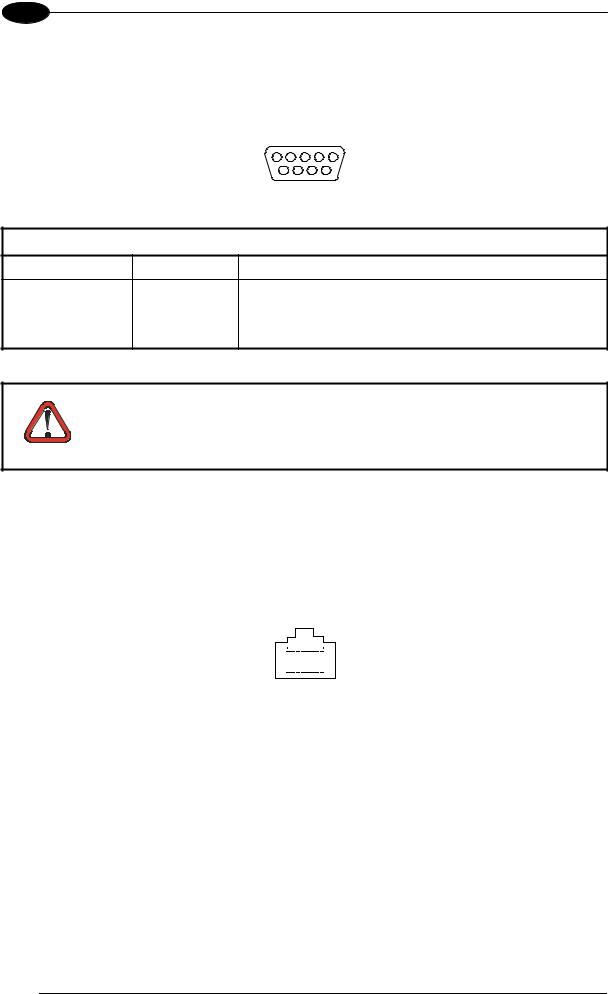
DB9-Pin Connector (RS232 Auxiliary Port)
There is also a separate 9-pin female D-sub connector for the Auxiliary port connection with the following pinout:
5 1
9 |
6 |
Figure 3 - 9-pin female D-Sub Connector
|
|
9-pin female D-sub connector pinout |
Pin |
Name |
Function |
2 |
TX |
Transmitted data of auxiliary RS232 |
3 |
RX |
Received data of auxiliary RS232 |
5 |
GND |
Reference GND of auxiliary RS232 |
1,4,6,7,8,9 |
N.C. |
Not connected |
|
If Matrix-2000™ is connected to a CBX with a BM100 Backup Module, |
|
|
then the Matrix-2000™ 9-pin Auxiliary port connector cannot be used for |
|
|
communication (i.e. configuration through VisiSet™). In this case use the |
|
CAUTION |
Auxiliary port 9-pin connector inside the CBX. |
|
RJ45 8-Pin Connector (Ethernet)
In Matrix-21XX models a RJ45 Modular Jack is provided for Ethernet connection. This interface and the connector pinout (see the following table) are IEEE 802.3 10 BaseT and IEEE 802.3u 100 BaseTx compliant. See par. 5.7 for connection details.
|
|
|
|
|
8 |
|
|
1 |
|
|
|
|
|
|
|
|
|
|
|
||
|
|
|
|
|
|
|
||||
|
|
Figure 4 - RJ45 Modular Jack |
||||||||
|
|
|
|
|||||||
|
|
RJ45 modular jack pinout |
||||||||
|
|
|
|
|
|
|
||||
Pin |
Name |
|
Function |
|
|
|
||||
1 |
TX + |
|
Transmitted data (+) |
|||||||
2 |
TX - |
|
Transmitted data (-) |
|||||||
3 |
RX + |
|
Received data (+) |
|||||||
6 |
RX - |
|
Received data (-) |
|||||||
4,5,7,8 |
N.C. |
|
Not connected |
|||||||
4
RAPID CONFIGURATION
1
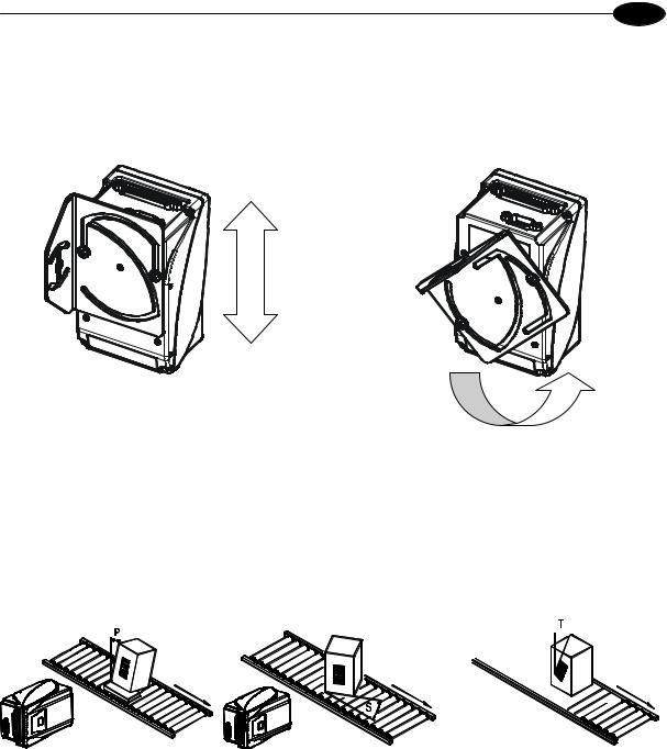
STEP 2 – MOUNTING AND POSITIONING THE SYSTEM
1.To mount the Matrix-2000™, use the mounting bracket to obtain the most suitable position for the reader as shown in the figures below.
Figure 5 - Positioning with Mounting Bracket
2.When mounting the Matrix-2000™ take into consideration these three ideal label position angles: Pitch or Skew 10° to 20° and Tilt 0°, although the reader can read a code at any Tilt angle.
Minimize |
Assure at least 10° |
Minimize |
Figure 6 – Pitch, Skew and Tilt Angles
3.Refer to the Reading Features in chp. 7 to determine the distance your reader should be positioned at.
5

1 |
Matrix-2000™ Reference Manual |
|
STEP 3 – AUTOLEARNING CONFIGURATION
An autolearning procedure is available to reduce installation time.
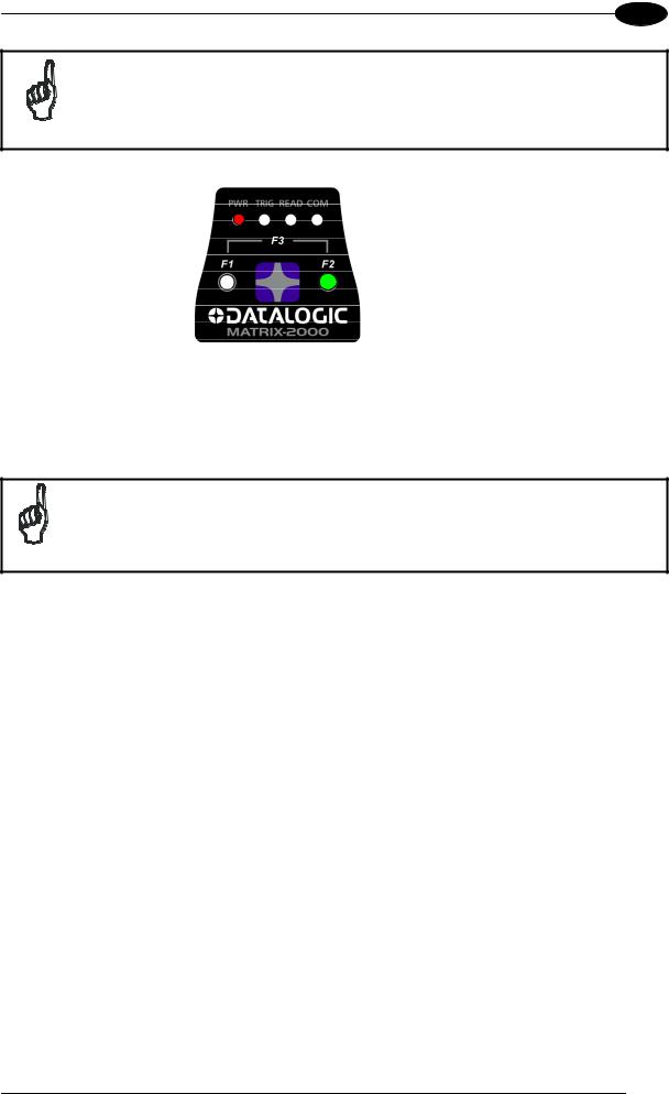
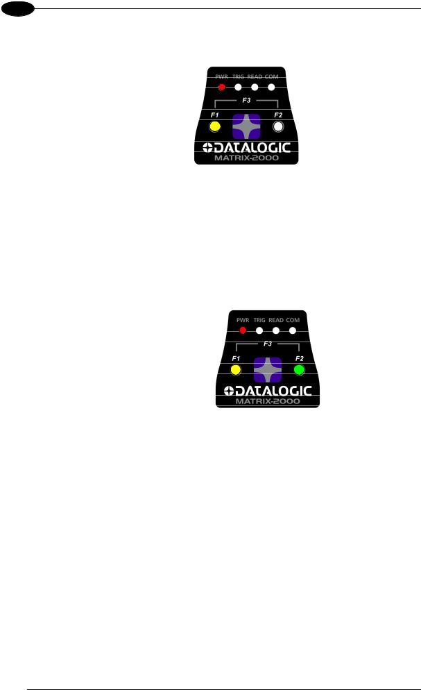
Status and diagnostic information are clearly presented by means of four colored LEDs, whereas the single push button and F1 and F2 LEDs give immediate access to the following relevant functions:
•Positioning (F1) gives visual feedback from the F1 LED to help center the code in the reader's FOV without external tools or software programs
•Auto Learn (F2) to self-detect and auto-configure calibration and code setting parameters
•Restore Default (F3) to return to factory default settings
The colors and meaning of the four status LEDs are illustrated in the following table:
PWR (red) |
This LED indicates the device is powered |
|
TRIG (yellow) |
This LED indicates the external trigger activity |
|
|
This LED confirms successful reading. It is also used to signal successful startup. At power |
|
READ (red) |
on this LED turns on and after a few seconds turns off. If the startup is not successful, this |
|
|
LED remains on. |
|
COM (green) |
This LED indicates active communication on the main serial port (Ethernet port for 21xx |
|
models). This LED is also software configurable. |
||
|
Auto Learn
If you are configuring your reader using the Auto Learn procedure:
1.Place the desired code in front of the reader at the correct reading distance (depending on the model, see the Reading Features table in chp 7).
2.Enter the Auto Learn function (F2) by pressing and holding the push button until only the F2 LED is on: Matrix-2000™ also beeps twice.
3.Release the button to enter the Auto Learn function.
Once entered, the reader acquires an image and automatically configures the optimal Exposure Time and Gain parameters for static reading, as well as detecting and recognizing the code, which is presented to it. The F2 LED blinks during this process.
4.At the end of the procedure, the new configuration parameters will be stored to permanent memory, the F2 LED remains on continuously and then the function automatically exits, the F2 LED turns off. Matrix-2000™ also emits 3 high pitched beeps.
If the Auto Learn calibration cannot be reached within a short timeout (max. 1 minute), Matrix-2000™ will exit without saving the configuration parameters, the F2 LED will not remain on continuously but it will just stop blinking. In this case, Matrix-2000™ emits a long low pitched beep.
To cancel the Auto Learn function without saving the configuration parameters, press and hold the keypad button at any time during the procedure: the F2 LED will stop blinking and Matrix-2000™ will emit a long low pitched beep.
6
RAPID CONFIGURATION
1
Autolearning configuration parameters can be saved to temporary memory only by selecting the "Autolearning Setup>Store Memory" parameter in VisiSet™.
NOTE |
The Autolearning function on the keypad button can also be disabled by the |
|
user via VisiSet™. |
||
|
Auto Learn (F2)
green
Figure 7 – Auto Learn Function
Repeat the procedure if needed, to program different code symbologies, however you must present only one code at a time to the reader.
Matrix-2000™ is able to decode any code symbology in its library with this procedure.
If your application has been configured using Auto Learn, your reader is ready. If necessary you can use VisiSet™ for advanced reader configuration.
NOTE
Positioning (Optional)
At the end of the Auto Learn procedure, you can use the Positioning procedure to center the code with respect to the reader's FOV.
1.While the desired code is in front of the reader at the correct reading distance, enter the Positioning function (F1) by pressing and holding the push button until only the F1 LED is on: Matrix-2000™ also beeps once.
2.Release the button to enter the Positioning function.
Once entered, the reader continuously acquires images and gives visual feedback using the F1 LED to indicate when the code is centered with respect to the reader's FOV. Slow blinking means that the positioning value must be improved.
3.To obtain the best value in terms of positioning, move the code and/or the reader so as to position the code as close as possible to the center of the Field of View, keeping the correct focus distance. Check F1 LED blinking: the best code positioning corresponds to fast (almost continuous) blinking.
4.After a short timeout the function automatically exits, the F1 LED remains on continuously and then stops blinking. Matrix-2000™ also emits 3 high pitched beeps.
If no valid code is present in the FOV, after about 3 minutes, Matrix-2000™ will automatically exit, the F1 LED will not remain on continuously but it will just stop blinking. In this case, Matrix-2000™ emits a long low pitched beep.
7
1 |
Matrix-2000™ Reference Manual |
|
To cancel the Positioning function, press and hold the keypad button at any time during the procedure: the F1 LED will stop blinking and Matrix-2000™ will emit a long low pitched beep.
Positioning (F1)
yellow
Figure 8 – Positioning Function
Restore Default (Optional)
At any time you can use the Restore Default procedure to return the reader to the factory default settings.
1.Enter the Restore Default function (F3) by pressing and holding the push button until both the F1 and F2 LEDs are on: Matrix-2000™ also beeps three times.
2.Release the button to perform the Restore Default function.
Restore Default (F3)
=F1 yellow +
F2 green
Figure 9 – Restore Default Function
8
RAPID CONFIGURATION
1
STEP 4 – INSTALLING VISISET™ CONFIGURATION PROGRAM
VisiSet™ is a Datalogic reader configuration tool providing several important advantages:
•Autolearning Wizard for rapid configuration and for new users;
•Defined configuration directly stored in the reader;
•Communication protocol independent from the physical interface allowing to consider the reader as a remote object to be configured and monitored.
To install VisiSet™, turn on the PC that will be used for the configuration, running Windows 98, 2000/NT, XP or Vista, then insert the VisiSet™ CD-ROM, wait for the CD to autorun and follow the installation procedure.
This configuration procedure assumes a laptop computer, running VisiSet™, is connected to the reader's auxiliary port.
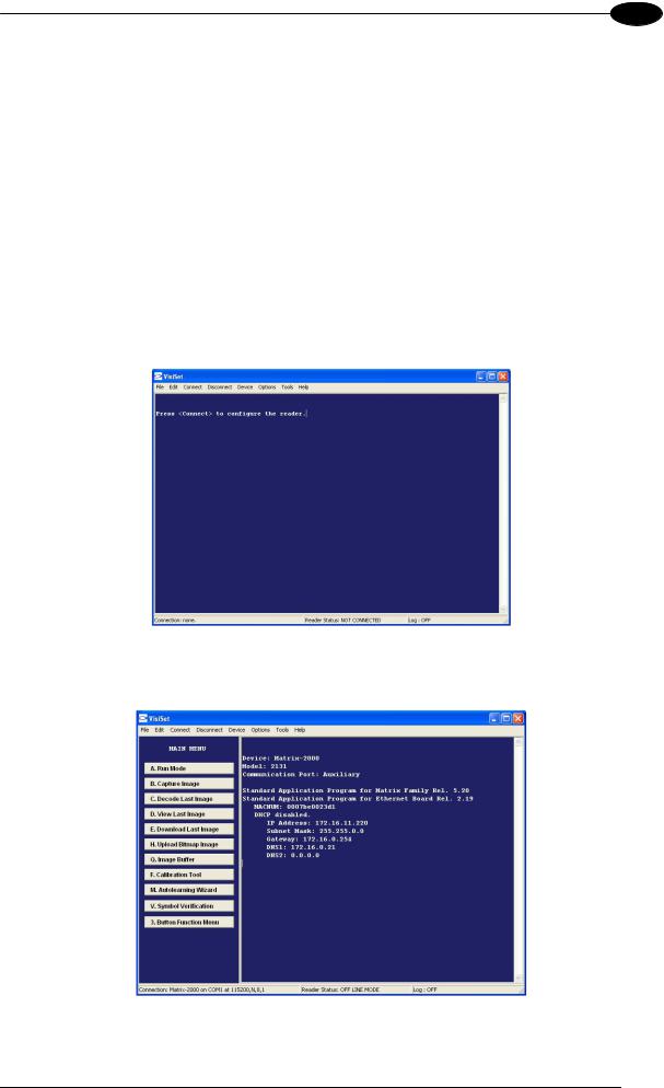
After installing and running the VisiSet™ software program the following window:
Figure 10 - VisiSet™ Opening Window
Set the communication parameters from the "Options" menu. Then select "Connect", the following window appears:
Figure 11 - VisiSet™ Main Window After Connection
The Autolearning Wizard option is advised for rapid configuration or for new users. It allows reader configuration in a few easy steps.
9

1 |
Matrix-2000™ Reference Manual |
|
STEP 5 – CONFIGURATION USING AUTOLEARNING WIZARD
1. Select the Autolearning Wizard button from the Main menu.
2.Place the desired code in front of the reader at the correct reading distance (depending on the model, see the Reading Features table in par. 7.1).
3.Press the "Positioning" button. The reader continuously acquires images and gives visual feedback in the view image window to indicate when the code is centered with respect to the reader's FOV. Move the reader (or code) to center it. Press the Positioning button again to stop positioning.
4.Select a Calibration Mode choice and press the "Calibrate" button.
3
4
5
Autolearning
Result
10
RAPID CONFIGURATION
1
The reader flashes once acquiring the image and auto determines the best exposure and gain settings. If the code symbology is enabled by default, the code will also be decoded.
5.If the code symbology is not enabled by default, select a Code Setting Mode choice and press the "Code Setting" button.
The Autolearning Result section of the Autolearning Wizard window shows the parameter settings and the code type results.
6. Select a Saving Options choice and press the "Save" button.
6
7. Close the AutoLearning Wizard.
|
If your application has been configured using the VisiSet™ Autolearning |
|
Wizard, your reader is ready. If necessary you can use VisiSet™ for advanced |
NOTE |
reader configuration. |
|
11
1 |
Matrix-2000™ Reference Manual |
|
ADVANCED READER CONFIGURATION
For further details on advanced product configuration, refer to the VisiSet™ Help On-Line.
The following are alternative or advanced reader configuration methods:
Advanced Configuration Using VisiSet™
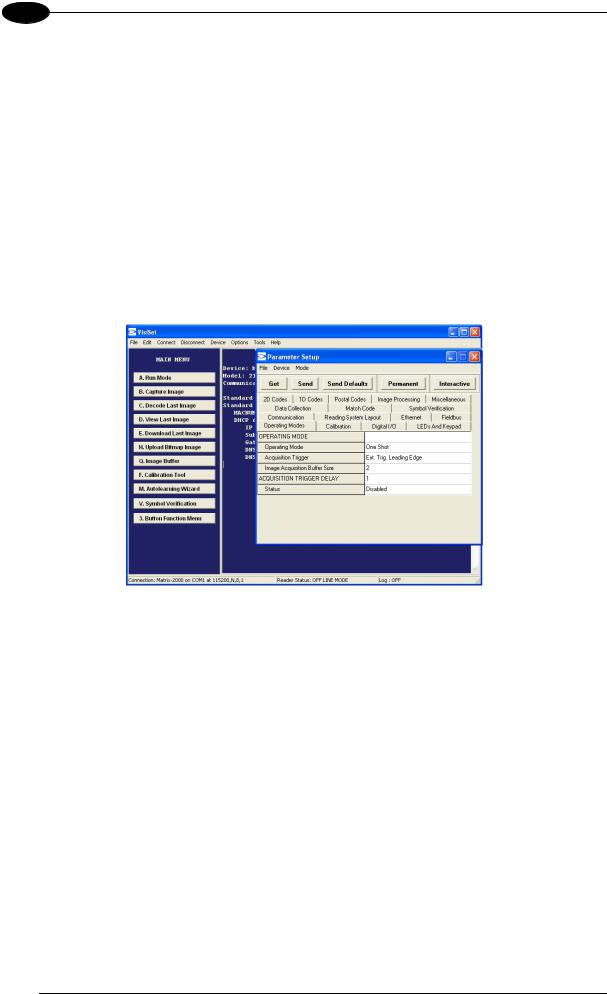
Advanced configuration can be performed through the VisiSet™ program by selecting
Device> Get Configuration From Temporary Memory to open the Parameter Setup window in off-line mode. Advanced configuration is addressed to expert users being able to complete a detailed reader configuration. The desired parameters can be defined in the various folders of the Parameter Setup window and then sent to the reader memory (either Temporary or Permanent):
Figure 12 - VisiSet™ Parameter Setup Window
Host Mode Programming
The reader can also be configured from a host computer using the Host Mode programming procedure, by commands via the serial interface. See the Host Mode Programming file on the CD-ROM.
Alternative Layouts
If you need to install an Ethernet network, Pass-Through network, Multiplexer network or an RS232 Master/Slave refer to chp. 6.
Code Quality Verification
Matrix-2000™ can be used as a Code Quality Verifier according to the ISO/IEC 15415, ISO/IEC 15416, AS9132, and AIM DPM Standards. For more details see the Matrix-2000™ Code Quality Verifier Solution manual on the CD-ROM.
12

GENERAL FEATURES
2
2 GENERAL FEATURES
2.1 INTRODUCTION
Matrix-2000™ is a Datalogic compact 2D reader designed and produced to be a high performance affordable solution for both linear and two-dimensional code reading applications. Matrix-2000™ has been developed for use in numerous applications, including PCB and electronic manufacturing, packaging lines, small item tracking, analysis machines and document handling systems, and can also be easily integrated into a wide range of OEM solutions.
Matrix-2000™ uses imaging technology and provides complete reading system functions by integrating: lighting system, image acquisition, image processing, decoding and communication into a single compact unit.
This technology intrinsically provides omni-directional reading.
Standard Application Program
A Standard Application Program is factory-loaded onto Matrix-2000™. This program controls code reading, data formatting, serial port and Ethernet interfacing, and many other operating and control parameters. It is completely user configurable from a Laptop or PC using the dedicated configuration software program VisiSet™, provided on CD-ROM with the reader.
There are different programmable operating modes to suit various code reading system requirements.
Quick, automatic calibration and positioning of the reader can be accomplished using the Autolearning button and LEDs on top of the reader without the necessity of a PC.
Autolearning can also be performed through VisiSet™ through the Autolearning Wizard. This tool includes visual feedback from the reader.
VisiSet™ provides a Calibration Tool to verify the exact positioning of the reader and to maximize its reading performance.
Statistics on the reading performance can also be visualized through a dedicated window in VisiSet™.
Symbol Verification can be performed through VisiSet™ when the reader has been installed and setup as a Verifier station. For details see the Matrix Symbol Verifier Solution manual.
Programmability
If your requirements are not met by the Standard Application Program, Custom Application Programs can be requested at your local Datalogic distributor.
13

2 |
Matrix-2000™ Reference Manual |
|
2.2 DESCRIPTION
Some of the main features of this reader are given below:
•Decoding of most popular linear and stacked barcodes, 2D code symbologies and postal codes
•Omni-directional reading
•Direct or 90° reading Window
•Quick installation without PC by using Autolearning button and F1, F2 LEDs
•Image Windowing function
•Frame rate up to 60 frames/sec (3600 frames/min)
•Up to 200 readable codes in the same reading phase
•Calibration Tool to verify exact code positioning in the Field of View and to maximize the reading performance
•Ethernet interface (Matrix-21XX only) with TCP/IP socket for reader parameter configuration, data and image transfer, HTTP server, FTP and mail client, etc.
•Windows-based VisiSet™ software to configure the reader parameter via PC serial or Ethernet interface
•Code quality assessment according to ISO/IEC 16022, ISO/IEC 18004, ISO/IEC 15415, ISO/IEC 15416 and AS9132 and AIM DPM standards.
•Different operating modes to suit various application requirements
•User-defined database of Image Acquisition Settings (parameter sets)
•Match Code option with a user-defined match code database
•Diagnostic software tools
•2 serial communication interfaces
•General purpose optocoupled I/Os
•Supply voltage ranges from 10 to 30 Vdc
The reader is contained in a magnesium alloy housing; the mechanical dimensions are 121 x 73 x 57 mm and it weighs about 380 g.
The protection class of the enclosure is IP64 for all 20XX models; therefore the reader is particularly suitable for industrial environments where protection against harsh external conditions is required.
Electrical connection of Power, Host interfaces and I/O signals is provided through a 25-pin connector (see Figure A, 9). In addition there is a 9-pin Auxiliary interface connector for reader configuration (see Figure A, 10). A standard Ethernet RJ45 connector is present on Matrix-21XX models (see Figure A, 11).
14

GENERAL FEATURES
2
The following indicators are located on the top of the reader:
PWR red LED indicates that the reader is connected to the power supply (see Figure A, 5).
TRIG yellow LED indicates external trigger activity (Figure A, 6).
READ red LED signals successful code decoding (Figure A, 7).
It is also used to signal successful startup. At power on this LED turns on and after a few seconds turns off. If the startup is not successful, this LED remains on.
COM green LED is software configurable. As default it indicates: data transmission on the main serial interface for Matrix-20XX models; Ethernet interface external connection for Matrix-21XX models (Figure A, 8).
F1 yellow LED signals distance of code from the center of FOV during the Positioning (Optional) procedure. The faster it blinks, the better Matrix-2000™ is positioned (see Figure A, 4).
F2 green LED signals reader calibration with respect to image quality during the Auto Learn procedure (see Figure A, 2).
The keypad button is software programmable. By default it starts the Auto Learn or Positioning procedure to calibrate and position the reader for quick installation without using a PC (see Figure A, 3).
15

2 |
Matrix-2000™ Reference Manual |
|
2.3 MODEL DESCRIPTION
The Matrix-2000™ reader is available in different versions according to the following characteristics:
MATRIX - 2XXX-X
Device Connectivity |
Optics |
Image Sensor |
Other Options |
||
0 |
= RS232/RS485 + RS232 |
1 |
= Ultra High Density (UHD) |
1 = VGA CCD |
R = 90° Reading Window |
1 |
= RS232/RS485 + |
2 |
= High Density (HD) |
|
|
|
RS232+ Ethernet |
3 |
= Standard Density (STD) |
|
|
|
|
4 |
= Low Density (LD) |
|
|
|
|
5 |
= Medium Range (MR) |
|
|
|
|
6 |
= Long Range (LR) |
|
|
2.4 ACCESSORIES
Order No. |
Accessory |
Description |
|
93A051351 |
CAB-S01 |
Cable to CBX (1 m) |
|
93A051352 |
CAB-S02 |
Cable to CBX (2 m) |
|
93A051353 |
CAB-S05 |
Cable to CBX (5 m) |
|
93A051354 |
CAB-S10 |
Cable to CBX (10 m) |
|
93A301067 |
CBX100 |
Compact Connection Box |
|
93A301069 |
CBX100LT |
Compact Connection Box Low Temp |
|
93A301068 |
CBX500 |
Modular Connection Box |
|
93ACC1808 |
BM100 |
Backup Module for CBX100/500 |
|
93ACC1809 |
* BM150 |
Display Module for CBX500 |
|
93ACC1810, |
* BM300/BM310 |
Profibus Module STD/IP65 for CBX500 |
|
93ACC1811 |
|||
|
|
||
93ACC1814 |
* BM400 |
DeviceNet Module IP65 for CBX500 |
|
93ACC1718 |
PG6002 |
AC/DC Power Supply Unit (US) |
|
93ACC1719 |
PG6001 |
AC/DC Power Supply Unit (UK) |
|
93ACC1720 |
PG6000 |
AC/DC Power Supply Unit (EU) |
|
93ACC1790 |
LTC-630 |
Four Bar Lighting System Controller |
|
93ACC1791 |
PH-1 |
Photocell Kit PNP |
|
93ACC1728 |
MEP543 |
Photocell Kit NPN |
|
93A401003 |
LT-100 |
Cone Lighting System |
|
93A401004 |
LT-200 |
Spot Lighting System |
|
93A401012 |
LT-210 |
Mini-Spot Lighting System |
|
93A401008 |
LT-300 |
Ring Lighting System |
|
93A401013 |
LT-314 |
45° Dark Field Ring Lighting System |
|
93A401014 |
LT-316 |
60° Dark Field Ring Lighting System |
|
93A401015 |
LT-410 |
Coaxial Lighting System |
|
93A401016 |
LT-510 |
Mini-Dome Lighting System |
|
93A401017 |
LT-511 |
Dome Lighting System |
|
93A401018 |
LT-630 |
Four Bar Lighting System |
|
93ACC1786 |
BK-410 |
Coaxial Lighting System Bracket |
|
93ACC1787 |
BK-510 |
Mini-Dome Lighting System Bracket |
|
93ACC1788 |
BK-511 |
Dome/Ring Lighting System Bracket |
|
93ACC1789 |
BK-630 |
Four Bar Lighting System Bracket |
|
93ACC1729 |
USX-60 |
Adjustable Bracket |
|
93A201090 |
GFC-MATRIX-2000 |
90° Deflection Mirror |
|
93ACC1841 |
ISO/IEC Calibration Chart |
Calibration Chart for Code Verifier Solution |
* Accessories compatible with Matrix-2000™ application software 5.20 and later.
16
GENERAL FEATURES
2
2.5 APPLICATION EXAMPLES
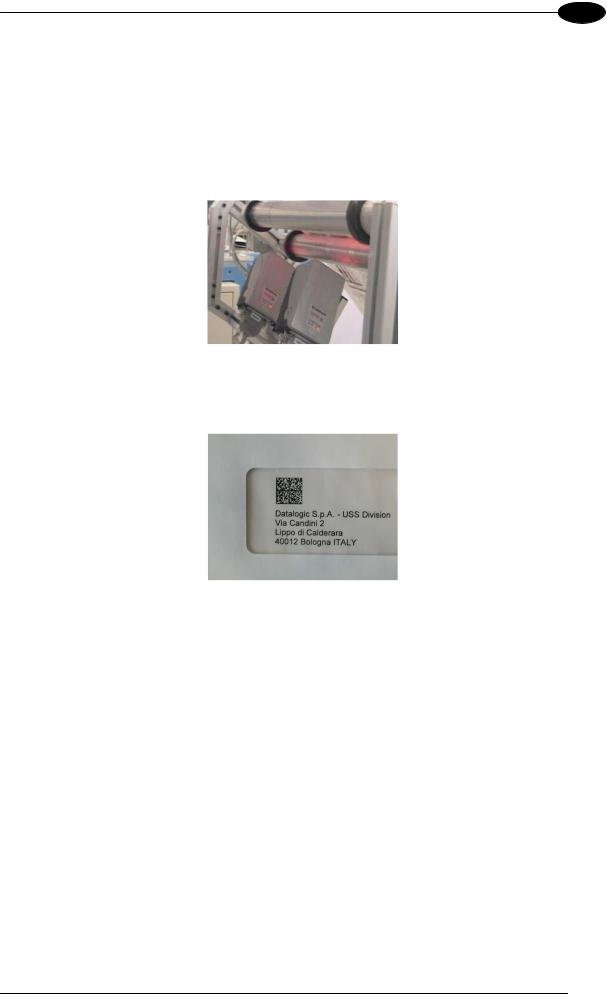
Matrix-2000™ is profitably used in the omnidirectional reading of 2D, stacked, linear and postal codes. The powerful LED illuminator, the Matrix 2XX1 60 fps CCD sensor and the 400 MHz CPU allow the decoding of fast moving codes (over 6.0 m/s) on industrial printing lines (see Figure 13) and in automated document handling and mail processing systems (see Figure 14).
Figure 13 - Matrix-2000™ Reading Station on a High Speed Printing Line
Figure 14 - Address Coded in Data Matrix Symbology for Automated Mail Processing
17
2 |
Matrix-2000™ Reference Manual |
|
Matrix-2000™ assures the reading of deformed and / or overprinted codes, even though damaged or printed on high reflective surfaces (see Figures 15,16,17).
Figure 15 - Unidose Flow-Pack with PDF417 Code
Figure 16 - Overprinted Barcode Readable by Matrix-2000™ also Through the Envelope Window Film
Figure 17 - Barcode Printed on Curved Surface Readable by Matrix-2000™ in spite of Image Optical Distortion
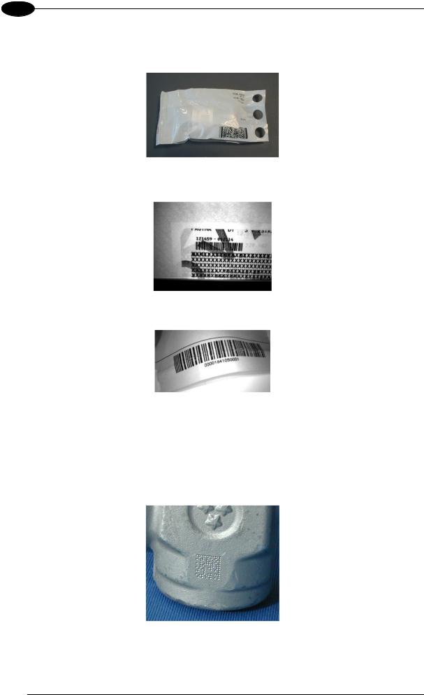
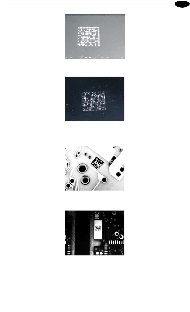
Matrix-2000™ is also very powerful in reading low-contrast direct part marked codes (see Figures 18, 19, 20, 21 and 22).
Figure 18 - Dot Matrix Code Directly Marked on Metal Surface by Using Dot Peening Technology
18
GENERAL FEATURES
2
Figure 19 - Dot Peening Marking on Metal Surface with Multi-dot per Code Element
Figure 20 - Directly Marked Dot Matrix Code Characterized by Outstanding Separation Distance between Adjacent Code Elements
Figure 21 - Data Matrix Code Directly Marked on PCB Surface by Using Laser Etching Technology
Figure 22 - Dot Matrix Code Directly Marked on PCB Copper Pad by Using Ink-Jet Technology
19

2 |
Matrix-2000™ Reference Manual |
|
2.6 EXTERNAL LIGHTING SYSTEMS
In some direct part marking applications best reading results are obtained by using an external lighting system. A series of accessory illuminators are available which cover a variety of applications.
The LT-100 Cone Lighting System provides a circular symmetrical light source designed for the following applications:
•with uneven or noisy background surfaces
•where dot peening or laser etching codes are directly marked onto metal surfaces or PCBs and need to be highlighted
•in the presence of highly reflective surfaces (metal, glass, etc.) causing direct reflections
Figure 23 - LT-100 Cone Lighting System
The LT-200 Spot Lighting System provides a high intensity light source designed for the following applications:
•with uneven, noisy and scratched surfaces
•where dot peening or laser etching codes are directly marked onto metal surfaces or PCBs and need to be highlighted. Here the use of more than one Spot Light can remove any shadowing effect.
•in the presence of highly reflective surfaces (metal, glass, etc.) causing direct reflections. Low light path to surface angles strongly reduce direct reflections.
Figure 24 - LT-200 Spot Lighting System
20
Loading...