


| <![if ! IE]> <![endif]>SERIES |
CONTROLS |
||
Instruction Manual |
|||
| <![if ! IE]> <![endif]>CONTROL |
|||
Field Programmable Closed Loop DC Speed Control |
|||
|
|
||
| <![if ! IE]> <![endif]>MDP |
P.O. Box 10 |
Phone (317) 873-5211 |
|
5000 W. 106th Street |
Fax (317) 873-1105 |
||
Zionsville, Indiana 46077 |
www.dartcontrols.com |
||
|
|
||
LT61 (0508) |
|
A-5-3241J |
|

Quick Jump
What models and options are available?
See page 3.
Looking for detailed specifications?
See page 3 & 4.
Want to get started fast?
See basic electrical hook-up details on page 8. See mechanical installation details on page 4 & 5. See some sample applications starting on page 24.
Need Help?
See troubleshooting on page 29.
Warranty
Dart Controls, Inc. (DCI) warrants its products to be free from defects in material and workmanship. The exclusive remedy for this warranty is DCI factory replacement of any part or parts of such product which shall within 12 months after delivery to the purchaser be returned to DCI factory with all transportation charges prepaid and which DCI determines to its satisfaction to be defective. This warranty shall not extend to defects in assembly by other than DCI or to any article which has been repaired or altered by other than DCI or to any article which DCI determines has been subjected to improper use. DCI assumes no responsibility for the design characteristics of any unit or its operation in any circuit or assembly. This warranty is in lieu of all other warranties, express or implied; all other liabilities or obligations on the part of DCI, including consequential damages, are hereby expressly excluded.
NOTE: Carefully check the control for shipping damage. Report any damage to the carrier immediately. Do not attempt to operate the drive if visible damage is evident to either the circuit or to the electronic components.
All information contained in this manual is intended to be correct, however information and data in this manual are subject to change without notice. DCI makes no warranty of any kind with regard to this information or data. Further, DCI is not responsible for any omissions or errors or consequential damage caused by the user of the product. DCI reserves the right to make manufacturing changes which may not be included in this manual.
WARNING
Improper installation or operation of this control may cause injury to personnel or control failure. The control must be installed in accordance with local, state, and national safety codes. Make certain that the power supply is disconnected before attempting to service or remove any components!!! If the power disconnect point is out of sight, lock it in disconnected position and tag to prevent unexpected application of power. Only a qualified electrician or service personnel should perform any electrical troubleshooting or maintenance. At no time should circuit continuity be checked by shorting terminals with a screwdriver or other metal device.
Table of Contents |
|
Introduction....................................................................................................................................... |
2 |
General Features .............................................................................................................................. |
2 |
Models & Options ............................................................................................................................. |
3 |
Model Table................................................................................................................................... |
3 |
Available Options .......................................................................................................................... |
3 |
Recommended Accessories......................................................................................................... |
3 |
Agency Approvals......................................................................................................................... |
3 |
Specifications ................................................................................................................................... |
3 |
Electrical ....................................................................................................................................... |
3 |
Mechanical ................................................................................................................................... |
4 |
Environmental............................................................................................................................... |
4 |
Dimension Chart........................................................................................................................... |
4 |
Installation and Mechanical Dimensions ....................................................................................... |
5 |
Exploded Panel View .................................................................................................................... |
5 |
Cut-out and Mounting Dimensions ............................................................................................... |
6 |
PU-E Series Pickup Installation.................................................................................................... |
7 |
Electrical Installation & Diagrams................................................................................................... |
8 |
P1 Terminal Block Hook-Up Diagrams.......................................................................................... |
8 |
P1 Terminal Block Descriptions .................................................................................................... |
9 |
-1 Option Wiring.......................................................................................................................... |
10 |
Basic Operating Instructions ........................................................................................................ |
10 |
Control Algorithm Discussion ..................................................................................................... |
10 |
Pulse-Accumulation Loop PI Tuning .......................................................................................... |
10 |
Master (Rate and Time) and Follower (Ratio) Modes Explained ................................................ |
11 |
Visual Reference ........................................................................................................................ |
12 |
How to Change a Parameter's Value (The Short Story) ............................................................. |
12 |
Operating the User Interface (The Long Story) .......................................................................... |
12 |
Detailed Configuration Instructions ............................................................................................. |
13 |
Default Configuration .................................................................................................................. |
13 |
Resetting the Unit to Factory Defaults ........................................................................................ |
13 |
JP1 (Program Enable Jumper) .................................................................................................. |
13 |
Software Parameters .................................................................................................................. |
14 |
Parameter Descriptions .............................................................................................................. |
16 |
Application Examples .................................................................................................................... |
24 |
Pump Controller with Audible and Visual Alarm ......................................................................... |
24 |
Conveyor Oven Controller with Two Preset Process Times........................................................ |
25 |
Synchronized Conveyor Controller with Jog Switch ................................................................... |
26 |
Troubleshooting.............................................................................................................................. |
29 |
Technical Support Options.......................................................................................................... |
29 |
What's Special About www.dartcontrols.com? ........................................................................... |
29 |
1
Introduction
The MDP series motor controls are compact, microprocessor-based units capable of being either field or factory configured for a number of industry's motion control needs. These controls are designed around a pulse-accumulation PI algorithm. They can be easily configured to operate as a digital speed controller, time-based process controller, or a ratiometric follower controller in master-slave systems. Utilizing Dart's new modular bus design techniques, the MDP series is ideal for volume OEM applications requiring specialized inputs and outputs. Contact Dart Controls' Sales Department for details. This flexibility makes the MDP series ideal for applications such as:
Water and Waste Treatment Systems
Conveyor Oven Controllers
Synchronized Conveyor Lines
Its durable 1/8 and 1/4 DIN aluminum housings can be easily mounted in a panel or control cabinet. New optional pluggable terminal block allows the installer to quickly install or replace units without the hassle of physically removing and reattaching wires. The units can be ordered with either standard European-style terminal block or optional “pluggable” connector.
General Features
-Microprocessor-based design combines the ultimate in responsiveness and accuracy in one package
-Digital closed-loop algorithm ensures long-term accuracy of +/-1/2 RPM of set speed or equiv.
-Non-volatile memory stores adjustable parameters even when power has been removed
-Factory or field programmable via front-panel keypad
-Adjustable parameters include min, max, accel, decel, display options, alarm options, etc.
-Internal program-enable jumper selectively prevents tampering with unit’s configuration
-Universal power supply accepts line voltages inputs from 85-265VAC @ 50-60Hz without switches
or jumpers. The unit automatically adjusts as needed.
-Transient voltage protection prolongs unit's life in harsh industrial environments
-Compatible with a variety of signal input types including: Hall-Effect Pickups, Photoelectric, TTL, etc. Note: Open collector devices must be capable of sinking 3mA.
-Self-contained power supply for external sensor, limited to 5V @ 50mA
-Programmable alarm output with Form C contacts rated to 250VAC @ 5A
-Flexible user inputs support inhibit, emergency stop, and jog functionality.
-1/8 and 1/4 DIN durable aluminum housing for panel mounting the MD10P and MD3P, respectively.
-Large 4 digit, 1/2” LED display
-G.E. Lexan membrane and gasket (which are included) meet NEMA 4X standards when used with NEMA 4X enclosures
-European terminal block or pluggable terminal block available
- Recognized, file #E78180 (MD10P, MD3P & MD3E)
-Wide operating ambient temperature range of -10C to 45C (14F to 113F)
-Multiple operating modes including:
•Master, Rate Mode – Controls in rate unit such as RPM, Gallons per Second, etc.
•Master, Time Mode – Controls in time unit such as HH:MM, MM:SS, SS:TT, or other unit
•FollowerMode–Controlsinpercentageofmasterrate.ThismodeallowstheMDPcontrolto precisely follow the actions of a master process without any long-term loss of position
2

Models & Options
Model Table
|
Input Voltage |
Output Voltage |
Max. Output H.P. |
Max Continuous |
Pickup or |
|
Model |
@ 120VAC |
@ 120VAC |
Armature DC |
Encoder |
||
@ 50 - 60Hz |
||||||
(@ 240VAC) |
(@240VAC) |
Amps |
Required? |
|||
|
||||||
|
|
|||||
|
|
|
|
|
|
|
MD10P |
85-265VAC |
90VDC |
1/2 |
5 |
Yes |
|
|
|
(180VDC) |
1 |
5 |
|
|
MD3P |
85-265VAC |
90VDC |
1 |
10 |
Yes |
|
|
|
(180VDC) |
2 |
10 |
|
|
MD3E |
85-265VAC |
90VDC |
1 |
10 |
Yes |
|
|
|
(180VDC) |
2 |
10 |
|
Available Options
Option Suffix |
Description |
Example |
-1 |
Expansion board which adds support for remote push button wiring via a |
MD10P-1, MD3P-1 |
|
European-style terminal block. |
|
|
|
|
|
|
|
-P |
Optional pluggable European-style terminal block |
MD10P-P, MD3P-1-P |
|
|
|
-9 |
Blank Lexan |
MD10P-9 |
Recommended Accessories
Model |
Description |
Pulses per |
RPM Range When Used With |
|
Revolution |
MD10P & MD3P |
|||
|
|
|||
|
|
|
|
|
PU-2E |
Hall-Effect Pickup, Single Channel |
1 |
1.0 – 50,000 RPM |
|
|
|
|
|
|
PU-4E |
Hall-Effect Pickup, Single Channel |
2 |
0.5 – 25,000 RPM |
|
|
|
|
|
|
PU-20E |
Hall-Effect Pickup, Single Channel |
10 |
0.1 – 5,000 RPM |
|
PU-40E |
Hall-Effect Pickup, Single Channel |
20 |
0.05 – 2,500 RPM |
Agency Approvals
Recognized Component MD10P, MD3P |
........................................................................................... E78180 |
|
MD3E .................................................................................................................................................... |
34M5 |
|
|
|
|
NEMA 4X .................................................................................................................................... |
MD10P / MD3P / MD3E |
|
|
|
|
Specifications |
|
|
Electrical |
|
|
|
|
|
Line Input Voltage........................................................................................................ |
Any Voltage from 85 - 265 VAC |
|
Line Input Frequency...................................................................................................... |
Any Freq. from 48 - 62 Hertz |
|
Signal Input Voltage Range .................................................................................. |
0 - 5VDC to 0 - 24VDC square wave |
|
Signal Input Frequency Range.................................................................................... |
0 – 50,000 Pulses per Minute |
|
(Higher frequencies are possible when using internal frequency divisor / prescaler) |
|
|
Display Range .................................................................................................................................... |
0.001 – 99,990 |
|
Units of Operation ..................................................................................................... |
User Programmable, any Unit |
|
Sensor / Pickup Power Supply ............................................................................................................... |
5V @ 50mA |
|
Isolated Alarm Relay Output Ratings .................................................................................................. |
250VAC @ 5A |
|
Average Armature Output Voltage................................................. |
Line Input Voltage Dependent (See model table) |
|
Design Overload Capacity............................................................................................................. |
200% for 1 minute |
|
|
|
|
3
Mechanical
Display Type ................................................................................................................ |
LED, Red, 4 Digit, ½” Height |
Housing Type MD10P & MD3P (with supplied gasket) .............................................................................. |
NEMA 4X |
MD3E NEMA 4 |
|
Connector Style (pluggable connector optional) ................................................... |
12-position 5mm European Style |
Terminal Block Torque Setting............................................................................................... |
4.4 in. lb. Max or .5Nm |
Faceplate Material......................................................................................... |
Polycarbonate with GE Lexan Overlay |
Housing Material ........................................................................................................................................ |
Aluminum |
Length MD10P & MD3P(Required Panel Depth) .......................................................................... |
4.625”, 117.48mm |
Faceplate Width ........................................................................................................................... |
4.539”, 115.29mm |
Weight MD10P ............................................................................................................. |
0.8425 lb, 13.48 oz, 382.14g |
MD3P................................................................................................................... |
1.52 lb, 24.32 oz, 689.44g |
MD3E................................................................................................................... |
1.64 lb, 26.24 oz, 743.88g |
Environmental
-----------------------------------------------------------------------------Operating Temperature Range |
|
|
|
-10C to 45C (15F to 115F) |
|
Operating Humidity Range ----------------------------------------------------------------------------------------- |
|
|
|
95%, non-condensing |
|
|
|
|
|
|
|
Dimension Chart |
|
|
|
|
|
|
|
|
|
|
|
|
Model |
Width |
Height |
Depth |
|
|
|
|
|
|
|
|
MD10P English (inches) |
|
|
|
|
|
Housing |
3.62 |
1.66 |
4.625 |
|
|
Lens |
4.539 |
2.289 |
0.375 |
|
|
MD10P Metric (millimeters) |
|
|
|
|
|
Housing |
91.94 |
42.16 |
117.27 |
|
|
Lens |
115.28 |
58.14 |
9.53 |
|
|
|
|
|
|
|
|
MD3P English (inches) |
|
|
|
|
|
Housing |
3.60 |
3.497 |
4.625 |
|
|
Lens |
4.539 |
4.179 |
0.375 |
|
|
MD3P Metric (millimeters) |
|
|
|
|
|
Housing |
91.44 |
88.82 |
117.27 |
|
|
Lens |
115.28 |
106.15 |
9.53 |
|
|
|
|
|
|
|
|
MD3E English (inches) |
|
|
|
|
|
Assembly |
5.53 |
7.40 |
3.90 |
|
|
|
|
|
|
|
|
MD3E Metric (millimeters) |
|
|
|
|
|
Assembly |
140.46 |
187.96 |
99.06 |
|
|
|
|
|
|
|
4
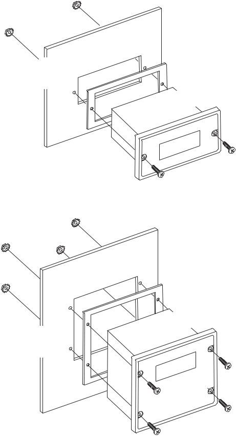
Installation and Mechanical Dimensions
Exploded Panel View
CUSTOMER
MOUNTING PANEL
(HOLE CUT-OUT FOR CONTROL HOUSING APPROXIMATELY 3.622" WIDE BY 1.770" HIGH)
SUPPLIED WITH EACH CONTROL:
1)GASKET
2)(2) 6-32 X 3/4 PANHEAD BLACK OXIDE STAINLESS SCREWS
3)(2) #6 NUT WITH LOCKWASHER
CUSTOMER
MOUNTING PANEL
(HOLE CUT-OUT FOR CONTROL HOUSING APPROXIMATELY 3.622" WIDE BY 3.622" HIGH)
PANEL MOUNTING GASKET
(WITH THE ADHESIVE SIDE OF GASKET FACING THE CUSTOMER MOUNTING PANEL)
MD10P
CONTROL
PANEL MOUNTING GASKET
(WITH THE ADHESIVE SIDE OF GASKET FACING THE CUSTOMER MOUNTING PANEL)
MD3P
CONTROL
SUPPLIED WITH EACH CONTROL:
1)GASKET
2)(4) 6-32 X 3/4 PANHEAD BLACK OXIDE STAINLESS SCREWS
3)(4) #6 NUT WITH LOCKWASHER
5

Cut-out and Mounting Dimensions
4.000" |
4.000" |
3.622" |
|
m |
Valu TaTachch |
|
MD10P |
CONTROLS |
Paggee IteIte |
|
|
|
|
|
|
|
|
|
|
|
ENTER |
HOUSING DEPTH |
|
|
|
|
|
|
|
|
|
4.625" |
|
MICRO-DRIVE |
.140" x 2 |
PANEL CUT-OUT |
|
|
|
|
||
3.622 |
ENTER
MD3P
.140" x 4
MICRO-DRIVE |
HOUSING DEPTH |
|
4.625" |
CONTROLS |
PANEL CUT-OUT |
|
MD10P and MD3P Dimensions
5.000"
5.000"
|
|
|
4.179" |
|
|
|
|
|
|
2.289" |
|
|
||
|
|
|||
1.656"
0.885" |
1.770" |
0.811" |
3.622" |
2.000" |
1.928"
4.625"
4.625"
6
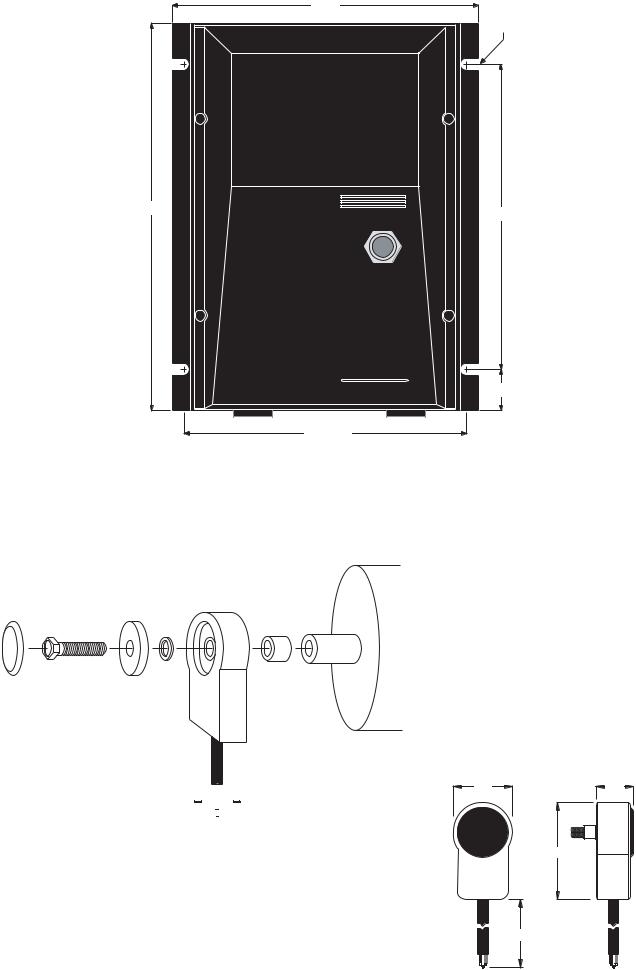
MD3E Mounting and Dimensions
|
|
5.530 |
7/32" TYP. |
|
|
|
(4 SLOTS) |
|
|
|
.350 DEEP |
Page |
Item |
Valu |
Tach |
|
|
|
ENTER |
|
CONTROLS |
|
|
7.400 |
|
|
5.500 |
|
|
|
|
|
|
|
ON |
|
|
|
OFF |
|
|
|
.750 |
|
|
5.125 TYP. |
|
PU-E Series Pickup Installation
The PU-E series pickup is an economical way to monitor motor speed. Its patented design provides for ease of installation in otherwise difficult to reach areas. The PU-E operates from a +5V power supply, producing a 5 volt square wave whose frequency is proportional to speed. This signal is fed into the MDP control as a speed or position reference for the microprocessor.
|
|
|
PU-E |
|
|
|
flat |
bearing |
tapped |
|
|
|
||
|
|
|
motor |
|
10-32 |
|
washer |
|
|
|
|
shaft |
||
|
|
|
||
screw |
|
|
|
|
dust |
magnet |
|
|
3/16" |
|
|
spacer |
||
cover |
disc |
|
|
|
black wire |
|
|
red wire |
|
common |
|
|
|
+5 volts |
|
|
|||
|
|
|
|
|
|
|
|
|
|
white wire signal
CAUTION:
DO NOT OVER TIGHTEN MOUNTING SCREW !!
No other mounting screws are necessary, as the cord will keep the unit from rotating.
Model |
Pulses per |
Number |
Revolution |
PU-2E |
1 |
PU-4E |
2 |
PU-20E |
10 |
PU-40E |
20 |
Dimensions
1.60 |
.875 |
|
2.40 |
72.00
7

Caution: The PU-E cord should not be grouped with other wires or cords. For applications with PU-E wire over 6 feet long, or noisy environments, a shielded cable is recommended. Connect the shield to the common terminal on the MDP, leaving the shield on the PU-E end floating.
Electrical Installation & Diagrams |
|||||||||
P1 Terminal Block Hook-Up Diagrams |
|
|
|
||||||
|
|
|
FUSE |
AC INPUT |
|
|
|
||
|
|
N |
AC INPUT } |
|
|
|
|||
|
P1-1 |
MD10P = 7.5 Amp* |
85-265VAC |
|
|||||
|
|
|
|||||||
|
|
MD3P = 15 Amp* |
|
||||||
|
|
L |
|
|
|
||||
|
P1-2 |
|
|
|
|
||||
|
P1-3 |
-A |
-ARM |
|
|
|
|
|
|
|
+A |
|
|
|
|
|
|
||
|
P1-4 |
+ARM |
|
|
MOTOR |
|
|||
MDP |
|
|
|
PICK-UP MOUNTED |
|||||
P1-5 |
COM |
|
|
|
|
|
|
||
COMMON |
black |
|
|
|
|
TO MOTOR SHAFT |
|||
|
|
|
|
|
|||||
MASTER |
P1-6 |
+5V |
+5VDC |
red |
|
|
|
|
|
|
|
|
|
|
|
||||
|
P1-7 |
S1 |
SIGNAL |
white |
|
|
|
|
|
|
S2 |
|
|
|
|
|
|||
|
P1-8 |
**Jog Input |
|
|
|
|
|
||
|
|
|
|
|
|
(Mounts on rotating |
|||
|
|
NO |
Alarm Output - Normally Open |
|
|
|
|
||
|
P1-9 |
} |
|
|
|
end shaft with 10-32 |
|||
|
C |
Alarm Output - Common |
Form C |
|
|
tapped hole, 1/2" deep) |
|||
|
P1-10 |
|
|
|
|||||
|
|
|
|
Relay Output |
|
||||
|
P1-11 |
NC |
Alarm Output - Normally Closed |
(Programmable) |
|
||||
|
IN1 |
User Input 1 |
|
|
|
|
|||
|
P1-12 |
|
|
|
|
|
|||
|
|
**INHIBIT |
|
|
|
|
|
|
|
|
|
|
|
|
|
|
|
|
|
|
|
|
COM (P1-5) |
|
|
|
black |
|
|
|
* For AC inputs utilizing two hot lines, both inputs should be |
white |
|||||||
|
protected with appropriately sized fuses or circuit breakers. |
|
|||||||
|
** P1-8 & P1-12 user input may be programmed |
|
|
|
|||||
|
for a number of functions. Including (jog, inhibit, etc.) |
|
|
|
|||||
|
|
|
FUSE |
AC INPUT |
|
|
|
||
|
|
N |
|
|
|
|
|
|
|
|
P1-1 |
MD10P = 7.5 Amp* |
|
|
|
85-265VAC |
|
||
|
|
|
|
|
|
||||
|
L |
MD3P = 15 Amp* |
AC INPUT } |
|
|
||||
|
P1-2 |
|
|
|
|||||
|
P1-3 |
-A |
-ARM |
|
|
|
|
|
|
|
+A |
|
|
|
|
|
|
||
|
P1-4 |
+ARM |
|
|
MOTOR |
FOLLOWER PICK-UP |
|||
|
|
|
|
||||||
MDP |
|
COM |
|
|
|
|
|
MOUNTED TO |
|
P1-5 |
|
|
|
|
|
MOTOR SHAFT |
|||
|
COMMON |
|
|
|
|
black |
|||
|
|
|
|
|
|
|
|
||
FOLLOWER |
P1-6 |
+5V |
+5VDC |
|
|
|
|
red |
|
|
|
|
|
|
|
||||
|
P1-7 |
S1 |
SIGNAL 1 |
|
|
|
|
white |
|
|
S2 |
|
|
|
|
|
|||
|
P1-8 |
|
SIGNAL 2 |
|
|
|
|||
|
|
|
|
|
(Mounts on rotating |
||||
|
P1-9 |
NO |
Alarm Output - Normally Open |
} |
|
|
|
end shaft with 10-32 |
|
|
C |
Alarm Output - Common |
Form C |
|
|
tapped hole, 1/2" deep) |
|||
|
|
|
|
|
|||||
|
P1-10 |
Relay Output |
|
||||||
|
|
|
|
|
|||||
|
P1-11 |
NC |
Alarm Output - Normally Closed |
(Programmable) |
|
||||
|
|
|
|
|
|
|
|||
|
P1-12 |
IN1 |
User Input 1 |
|
|
|
|
|
|
|
|
**INHIBIT |
|
|
|
|
|
|
|
|
|
|
|
|
|
|
|
|
|
|
|
|
COM (P1-5) |
|
|
|
|
|
|
*For AC inputs utilizing two hot lines, both inputs should be protected with appropriately sized fuses or circuit breakers.
**P1-8 & P1-12 user input may be programmed
for a number of functions. Including (jog, inhibit, etc.)
8
 Loading...