


250G Control Series

250G CONTROL SERIES
P.O. Box 10
5000 W. 106th Street
Zionsville, Indiana 46077
Phone (317) 873-5211
Fax (317) 873-1105
www.dartcontrols.com
Instruction Manual
Variable Speed DC Control
CONTROLS

1
WARRANTY
Dart Controls, Inc. (DCI) warrants its products to be free from defects in material and workmanship. The exclusive remedy for
this warranty is DCI factory replacement of any part or parts of such product which shall within 12 months after delivery to the
purchaser be returned to DCI factory with all transportation charges prepaid and which DCI determines to its satisfaction to be
defective. This warranty shall not extend to defects in assembly by other than DCI or to any article which has been repaired or
altered by other than DCI or to any article which DCI determines has been subjected to improper use. DCI assumes no responsibility
for the design characteristics of any unit or its operation in any circuit or assembly. This warranty is in lieu of all other warranties,
express or implied; all other liabilities or obligations on the part of DCI, including consequential damages, are hereby expressly
excluded.
NOTE: Carefully check the control for shipping damage. Report any damage to the carrier immediately. Do not attempt to operate
the drive if visible damage is evident to either the circuit or to the electronic components.
All information contained in this manual is intended to be correct, however information and data in this manual are subject to change
without notice. DCI makes no warranty of any kind with regard to this information or data. Further, DCI is not responsible for any
omissions or errors or consequential damage caused by the user of the product. DCI reserves the right to make manufacturing
changes which may not be included in this manual.
WARNING
Improper installation or operation of this control may cause injury to personnel or control failure. The control must be
installed in accordance with local, state, and national safety codes. Make certain that the power supply is disconnected
before attempting to service or remove any components!!! If the power disconnect point is out of sight, lock it in
disconnected position and tag to prevent unexpected application of power. Only a qualified electrician or service
personnel should perform any electrical troubleshooting or maintenance. At no time should circuit continuity be checked
by shorting terminals with a screwdriver or other metal device.
WARRANTY ............................................................................................................................................................................... 1
INTRODUCTION ......................................................................................................................................................................... 2
CONTROL FEATURES .............................................................................................................................................................. 2
HEATSINK DIMENSIONS .......................................................................................................................................................... 2
SPEEDPOT KIT ASSEMBLY ..................................................................................................................................................... 3
MOUNTING PROCEDURE ......................................................................................................................................................... 3
MODEL SELECTION .................................................................................................................................................................. 3
WIRING PROCEDURE & FUSING ............................................................................................................................................. 4
TERMINAL STRIP WIRING ........................................................................................................................................................ 4
CHASSIS & ENCLOSED MODEL HOOK-UP DIAGRAMS ....................................................................................................... 5
START-UP PROCEDURE & ADJUSTMENTS .......................................................................................................................... 6
TRIMPOT ADJUSTMENT PROCEDURE .................................................................................................................................. 6
TRIMPOT SETTING CHART ...................................................................................................................................................... 7
CONTROL MODIFICATIONS .................................................................................................................................................. 7-8
TWO SPEED OPERATION ...............................................................................................................................................
17
DYNAMIC BRAKING ........................................................................................................................................................
17
TACH FEEDBACK & FOLLOWER ...................................................................................................................................
18
INHIBIT INSTRUCTIONS ..................................................................................................................................................
18
OPTION DESCRIPTION ........................................................................................................................................................ 8-12
-5 OPTION ........................................................................................................................................................................... 8
-7 / -9 OPTIONS ................................................................................................................................................................... 9
-11 / -17B / -29 / -29B / -34A OPTIONS ............................................................................................................................ 10
-55G2 / -56G2 CHASSIS OPTIONS & ADJUSTMENT PROCEDURE ............................................................................ 11
-56G2 ENCLOSED OPTION ............................................................................................................................................. 12
IN CASE OF DIFFICULTY ........................................................................................................................................................ 12
SPECIFICATIONS & TYPICAL MOTOR CURRENTS ............................................................................................................. 13
250G SERIES PARTS PLACEMENT & LIST .......................................................................................................................... 13
250G SERIES SCHEMATIC ..................................................................................................................................................... 14
REPAIR PROCEDURE & PRODUCT LINE ........................................................................................................ BACK COVER
TABLE OF CONTENTS
2
INTRODUCTION
• The Dart 250G Series variable speed DC motor control is a versatile, general purpose control rated to 2 HP, available in chassis
mount or enclosed configurations; with options for specific applications.
• The 251G model is available with an adjustable HP range of 1/50 thru 1/8 at 120 VAC input.
• The 253G model has a dual voltage input (may accommodate either 120 or 240 VAC). It is available with an adjustable HP
range of 1/8 thru 1 HP for 120 VAC, and 1/4 thru 2 HP for 240 VAC input.
• Designed for DC Permanent Magnet, Shunt Wound, and some Universal (AC/DC) motors in the above horsepower ranges.
• Incoming AC voltage is also converted to adjustable full wave rectified DC voltage (via a packaged bridge) to operate the DC
motor. Also, a full wave field voltage is provided for shunt wound motors (see page 4 for voltages).
• The control incorporates transient voltage protection with adjustable current limit and an AC fuse for protection. It features adjust-
able minimum and maximum speeds along with adjustable acceleration and IR Compensation. Tach feedback is accomplished
thru a connection to a pin (P2) on the printed circuit board.
• The 250G Series has a linear acceleration/deceleration ramp.
• The control also has a barrier type terminal strip for all power and control wiring.
• The enclosed model uses a gasketed cover assembly that is rated NEMA 4/12.
• cU.L.us Listed.
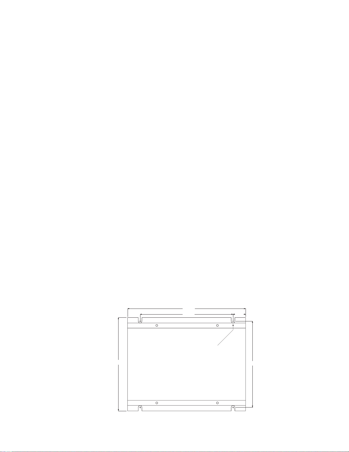
HEATSINK DIMENSIONS
FOR CHASSIS VERSION: Allow 1.55" for height clearance, 7.00" for overall length.
FOR ENCLOSED VERSION: Allow 3.50" for height clearance, 7.40" for overall length.
MIN. SPEED (minimum speed) - Allows adjustment of the motor speed when the speedpot is set at minimum (CCW). This permits
the user to eliminate the “deadband” on the main speed control permitting zero calibration. Clockwise rotation of “MIN” trimpot
increases minimum motor speed.
MAX. SPEED (maximum speed) - provides for adjustment of the motor speed when the speedpot is set at maximum (CW). This
permits the user to eliminate the top end “deadband”, which will provide full speed at maximum rotation. Rotation of the “MAX”
trimpot in the clockwise direction increases the maximum motor speed.
ACCEL (acceleration) - allows adjustment of the motor acceleration from a minimum of 0.5 seconds to approximately 8.0
seconds. The deceleration time depends on the ACCEL setting. For DECEL time equal to ACCEL time, see -17B option.
I. R. COMP (speed regulation) - adjusts the control output to compensate for speed changes caused by varying motor loads. As
the motor load is increased, I.R. COMP increases the voltage output of the control. Clockwise rotation of the “I.R. COMP” trimpot
will increase compensation.
CUR. LIM. (current limit) - provides protection from excessive armature current by limiting the maximum armature current the
control can provide. This enables adjustment of the maximum torque the motor can deliver. Current limit adjustment (CUR LIM)
is set at 125% of the rated motor current (torque) based on horsepower. Clockwise rotation of the “CUR LIM” trimpot increases
the current (torque) the control will provide.
INHIBIT TERMINAL PIN (P2) - allows the user a choice of stopping and starting hard (fast) or stopping hard with a soft start through
an adjustable acceleration ramp, without breaking the AC lines (see page 8).
TERMINAL STRIP - allows for connection of AC lines, motor leads, motor field (if needed), and speed potentiometer.
CONTROL FEATURES
5.500
7.000
.750
5.125
7/32 SLOTS (4)
TYP. .350 DEEP
5.530

3
WARNING
1. Be sure the control housing is properly grounded.
2. Arm connections must not be switched or broken while the control is on. Serious damage may result.
3. For non-speedpot applications, the input connections to the Lo-Wiper-Hi leads must not be grounded. Serious
control damage may result from a grounded input.
SPEEDPOT KIT ASSEMBLY
MOUNTING PROCEDURE
CAUTION: Do not mount control where ambient temperature is outside the range of -10
o
C. (15
o
F.) to 45
o
C. (115
o
F.)
1. Four 7/32" diameter slots are provided for control mounting.
2. The chassis of the control can be used as a template.
3. Use standard hardware to mount.
4. The enclosed version has two threaded holes (1/2" NPT) provided on the bottom side endplate near the terminal strip to
facilitate wiring.
MODEL SELECTION
The 251G will operate a 90 VDC motor in the H.P. range of 1/50 through 1/8 H.P., using different trimpot settings. The 253G will
operate a 90 VDC motor in the H.P. range of 1/8 through 1 H.P., and a 180 VDC motor in the range of 1/4 through 2 H.P., using
different trimpot settings.
* Not available with 120 VAC input - Input voltage determines maximum allowable H.P.
INPUT OUTPUT OUTPUT CHASSIS ENCLOSED
HORSEPOWER VOLTAGE VOLTAGE AMPS DC MODEL MODEL
1/50
1/20 120 VAC 0-90 VDC 1.2A 251G-12C 251G-12E
1/8
1/8
1/4
1/3
1/2
3/4
1.0
1.5*
2.0*
120/240 VAC 0-90/0-180 VDC 10.8A 253G-200C 253G-200E
Note: The minimum current rating for all 250G controls is 150mA.
240 VAC 0-180 VDC 10.8A 253G-200C 253G-200E
SPEEDPOT
(5K 2W)
CUSTOMER'S
MOUNTING BRACKET
DIALPLATE
2.00" dia.
LOCK
WASHER
O-RING
HEX NUT
SPEEDPOT
KNOB
.437
3/8
DIA.
5/32
DIA.
SPEEDPOT LOCATOR HOLE DIMENSIONS
.500 .370 .370
1.240
1.250
.250 Dia.

4
P1-7
(-FIELD) Connect minus (-) Field wire of SHUNT WOUND MOTOR.
P1-8
VERY IMPORTANT !!! Refer to “CUSTOMER FUSING”, shown above.
P1-9
CHASSIS VERSION: (SPARE) Make no connection to P1-8 or P1-9
ENCLOSED VERSION: (AC)
120VAC
-Connect incoming hot AC (black wire) to P1-9 and Neutral (white wire) to
P1-8. Connect ground (green wire) to Chassis Ground, as shown in
diagram - page 5.
240VAC
- Connect both hot sides, one to P1-8 and one to P1-9. Also connect ground
wire to Chassis Ground.
P1-10
VERY IMPORTANT !!! Refer to “CUSTOMER FUSING”, shown above.
P1-11
CHASSIS VERSION: (AC)
120VAC
- Connect incoming hot AC (brown or black wire) to P1-11 and Neutral (white
or yellow wire) to P1-10. Connect ground (green wire) to Chassis Ground.
240VAC
- Connect both hot sides, one to P1-10 and one to P1-11. Connect ground
wire to Chassis Ground.
ENCLOSED VERSION: (SWITCHED AC) No connections to P1-10 and P1-11. This is for switched AC output. Note
“FACTORY WIRING” (page 5). Pilot lights can be connected between
these terminals. The voltage present at these terminals is AC input voltage.
FIELD VOLTAGE TABLE
VAC INPUT 120 240
VDC FIELD 100 200
}
}
P1-1
(SPEEDPOT LO) Connects to low side (orange wire) of the 5K speedpot (normally the CCW end). This input is raised and
lowered by the MIN. trimpot. Electronic speed input (voltage follower) may be referenced to speedpot LO if the MIN trimpot
adjustments are to be active. Otherwise, inputs may be referenced to -ARM, which will bypass the MIN trimpot.
NOTE: INPUT MUST NOT BE GROUNDED!!
P1-2
(SPEEDPOT WIPER) Connects to wiper (red wire) of the 5K speedpot (center lead). For voltage follower applications, this
INPUT MUST NOT BE GREATER THAN +12 VOLTS MAXIMUM AND MUST NOT BE GROUNDED!
P1-3
(SPEEDPOT HI) Connects to high side (white wire) of the 5K speedpot (CW end). This is internal +12 volts. For start-stop
applications, the connection between this terminal and speedpot HI can be opened and closed by a SPST switch.
NOTE: INPUT MUST NOT BE GROUNDED!!
P1-4
(-ARM) Connects to minus (-) Armature wire (A2) on motor. For voltage follower applications where the MIN trimpot is
bypassed, connect minus (-) of the follower to this terminal.
P1-5
(+ARM) Connects to plus (+) Armature wire (A1) on motor. 0-90 VDC for 120 VAC input OR 0-180 VDC for 240 VAC input.
See “SPECIFICATIONS” for output rating.
P1-6
(+FIELD) DO NOT USE for permanent magnet motor. This supplies +Field voltage for a SHUNT WOUND MOTOR. Refer
to Field Voltage table. For motors with dual voltage field (i.e. 50/100V or 100/200V), make sure highest value is connected.
WIRING PROCEDURE
1. Size all wires which carry armature or line current to handle currents as specified by national, state, and/or local codes. All other
wires may be #18 AWG or smaller as permitted by local code.
2. Separate control wires from all the Armature and AC line wires when routed in conduits or in wire trays. The enclosed version
has two threaded holes (1/2" NPT) in one endplate, located near the terminal strip, for this purpose.
The 250G Series has an 11 position terminal strip for ease of connection.
TERMINAL STRIP WIRING
FUSING
The 250G is provided with a fuse in AC line 1 (P1-11). This fuse is sized to open in the event of a shorted armature or if an armature
line is shorted to earth ground. As long as 120 VAC input is connected properly, there is no additional fusing needed.
For 240 VAC applications, an external fuse may be used in AC line 2 (P1-10). This fuse should be a Bussman ABC10 or LittleFuse
314-010. This added fuse will provide protection on both AC legs to the 250G. If you desire not to fuse both legs, the fuse in the
control will open in the event of excessive armature currents.
Note: AC current is determined by motor characteristics. In some applications it may be necessary to increase fuse value.
 Loading...