


| <![if ! IE]> <![endif]>SERIES |
CONTROLS |
|
||
Instruction Manual |
||||
| <![if ! IE]> <![endif]>CONTROL |
||||
Variable Speed Control |
|
|||
|
|
|
||
| <![if ! IE]> <![endif]>125D |
P.O. Box 10 |
Phone (317) |
873-5211 |
|
5000 W. 106th Street |
Fax (317) |
873-1105 |
||
Zionsville, Indiana 46077 |
www.dartcontrols.com |
|||
LT125D (0408) |
|
|
A-5-3262D |
|

TABLE OF CONTENTS |
|
WARRANTY ............................................................................................................................................................................... |
1 |
INTRODUCTION ........................................................................................................................................................................ |
2 |
CONTROL FEATURES .............................................................................................................................................................. |
2 |
125D SERIES HEATSINK DIMENSIONS .................................................................................................................................. |
2 |
MOUNTING PROCEDURE ........................................................................................................................................................ |
3 |
MODEL SELECTION ................................................................................................................................................................. |
3 |
WIRING PROCEDURE & FUSING ............................................................................................................................................ |
3 |
TERMINAL STRIP WIRING INSTRUCTIONS ........................................................................................................................... |
3 |
123D / 125D HOOK-UP DIAGRAM ........................................................................................................................................... |
4 |
CONTROL START-UP ............................................................................................................................................................... |
4 |
TRIMPOT ADJUSTMENT CHART & PROCEDURE ................................................................................................................. |
5 |
CONTROL MODIFICATIONS .................................................................................................................................................... |
6 |
TWO SPEED OPERATION .................................................................................................................................................. |
6 |
DYNAMIC BRAKING ............................................................................................................................................................ |
6 |
TACH FEEDBACK/FOLLOWER .......................................................................................................................................... |
6 |
INHIBIT FUNCTIONS ........................................................................................................................................................... |
6 |
SPEEDPOT KIT ASSEMBLY ..................................................................................................................................................... |
7 |
OPTION DESCRIPTION ...................................................................................................................................................... |
7-10 |
-1 / -2A OPTIONS ................................................................................................................................................................... |
7 |
-5 / -7 OPTIONS .................................................................................................................................................................. |
8-9 |
-11 / -15B / -K OPTIONS / -29B OPTIONS ............................................................................................................................ |
9 |
-55G / -56G OPTION ........................................................................................................................................................... |
10 |
IN CASE OF DIFFICULTY ....................................................................................................................................................... |
11 |
SPECIFICATIONS .................................................................................................................................................................... |
11 |
TYPICAL MOTOR CURRENTS ............................................................................................................................................... |
12 |
125D SERIES PARTS PLACEMENT & LIST .......................................................................................................................... |
12 |
125D SERIES SCHEMATIC ..................................................................................................................................................... |
13 |
PRODUCT LINE .................................................................................................................................................. |
BACK COVER |
WARRANTY
Dart Controls, Inc. (DCI) warrants its products to be free from defects in material and workmanship. The exclusive remedy for this warranty is DCI factory replacement of any part or parts of such product which shall within 12 months after delivery to the purchaser be returned to DCI factory with all transportation charges prepaid and which DCI determines to its satisfaction to be defective. This warranty shall not extend to defects in assembly by other than DCI or to any article which has been repaired or altered by other than DCI or to any article which DCI determines has been subjected to improper use. DCI assumes no responsibility for the design characteristics of any unit or its operation in any circuit or assembly. This warranty is in lieu of all other warranties, express or implied; all other liabilities or obligations on the part of DCI, including consequential damages, are hereby expressly excluded.
NOTE: Carefully check the control for shipping damage. Report any damage to the carrier immediately. Do not attempt to operate the drive if visible damage is evident to either the circuit or to the electronic components.
All information contained in this manual is intended to be correct, however information and data in this manual are subject to change without notice. DCI makes no warranty of any kind with regard to this information or data. Further, DCI is not responsible for any omissions or errors or consequential damage caused by the user of the product. DCI reserves the right to make manufacturing changes which may not be included in this manual.
WARNING
Improper installation or operation of this control may cause injury to personnel or control failure. The control must be installed in accordance with local, state, and national safety codes. Make certain that the power supply is disconnected before attempting to service or remove any components!!! If the power disconnect point is out of sight, lock it in disconnected position and tag to prevent unexpected application of power. Only a qualified electrician or service personnel should perform any electrical troubleshooting or maintenance. At no time should circuit continuity be checked by shorting terminals with a screwdriver or other metal device.
1
INTRODUCTION
•The 123D variable speed control is available in a range of 150mA through 5.5 ADC (or up to 10 ADC if using a suitable external heatsink) at 24 through 36 VAC input.
•The 125D variable speed control is available in a range of 150mA through 1/4 H.P. at 120/240 VAC input.
•The 125DV variable speed control is available in a range of 1/8 through 1 H.P. at 120/240 VAC input. With -HS(125D) or suitable external heatsink (where 125D extrusion temperature does not exceed 70° C.), maximum U.L./C.S.A. rating can be increased to 2 H.P. and 10 Amps DC.
•The control is designed for DC Permanent Magnet, Shunt Wound, and some Universal (AC/DC) motors in the above horsepower ranges.
•Incoming AC voltage is converted to adjustable full wave rectified DC voltage to operate the DC motor. Also, a full wave field voltage is provided for shunt wound motors (see page 11 for voltages).
•The control incorporates transient voltage protection with adjustable current limit which fits into a compact package. It features adjustable minimum and maximum speeds along with adjustable IR compensation and an inhibit function.
•Options are available to change ACCEL/DECEL time (see page 8, -15 / -K options).
•cULus Recognized under, U.L. File # E78180.
CONTROL FEATURES
MINIMUM SPEED - Allows adjustment of the motor speed when the speedpot is set at minimum (CCW). This permits the user to eliminate "Deadband" on the main speed control, permitting zero calibration. Clockwise rotation of "MIN" trimpot increases speed.
MAX SPEED (Maximum Speed) - Allows adjustment of the motor speed when the speedpot is set at maximum (CW). This permits the user to eliminate the top end "Deadband", which will provide full speed at maximum rotation. Rotation of the "MAX" trimpot in the clockwise direction increases the maximum motor speed.
I.R. COMP (Speed Regulation) - This allows for adjustment of the circuitry that controls the speed regulation of the motor. The circuitry controls armature speed by changing the armature voltage to compensate for increased or decreased motor loading. Clockwise rotation of the "IR COMP" trimpot will increase compensation.
CUR. LIM. (Current Limit) - Provides protection from excessive armature current by limiting the maximum armature current the control can provide. This enables adjustment of the maximum torque the motor can deliver. Torque adjustment (Cur. Lim.) is preset at 125% of rated motor torque (current) based on horsepower. Clockwise rotation of the "CUR. LIM." trimpot increases the torque (current) the control will provide.
INHIBIT TERMINAL PIN - Allows the user a choice of stopping and starting hard (fast) or stopping hard with a soft start through an adjustable acceleration ramp, without breaking the AC lines (see page 6).
TERMINAL STRIP - Allows for connection of AC lines, motor leads, motor field (if needed), and speed potentiometer
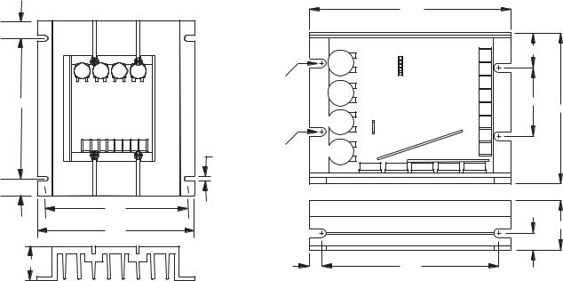
125D SERIES HEATSINK DIMENSIONS
AUXILIARY HEATSINK -HS(125D) |
STANDARD HEATSINK |
|
|
|
|
4.250" |
|
|
.6875 |
|
|
|
|
|
|
|
|
|
|
|
P1 |
.694" |
|
|
|
|
|
-8 |
|
|
|
MIN |
|
P2 |
|
|
|
|
|
|
|
||
|
|
|
ADDER BOARD |
-7 |
|
|
|
|
|
|
CONNECTOR |
|
|
|
|
|
|
|
|
|
|
.188" DIA. |
|
|
|
-6 |
|
|
(6 SLOTS) |
MAX |
|
|
-5 |
|
5.625 |
|
|
|
1.750" |
||
|
|
|
|
-4 |
||
|
|
|
|
|
3.625" |
|
|
|
IR COMP |
P3 |
|
-3 |
|
|
|
|
INHIBIT |
|
|
|
|
11/32" |
|
PIN |
|
-2 |
|
|
|
|
|
-1 |
|
|
.218 |
SLOT |
CUR LIM |
|
|
|
|
DEPTH |
|
|
|
|
|
|
.6875 |
|
|
|
|
|
|
5.625 |
|
|
|
|
|
|
6.250 |
|
|
|
|
|
1.300" |
|
|
|
|
|
|
|
|
|
|
|
|
|
.380" |
1.375 |
.249" |
|
|
3.750" |
|
|
|
|
|
|
|
||
2

MOUNTING PROCEDURE
1.Six 3/16" wide slots are provided for control mounting.
2.Control chassis can be used as a template.
3.Use standard hardware to mount.
CAUTION:
DO NOT MOUNT WHERE AMBIENT TEMPERATURE IS OUTSIDE THE RANGE OF -10o C (15o F) TO 45o C (115o F)
MODEL SELECTION
|
INPUT |
OUTPUT |
OUTPUT* |
MODEL |
HORSEPOWER |
VOLTAGE |
VOLTAGE |
AMPS DC |
NUMBER |
|
|
|
|
|
150mA thru 5.5 A |
24 to 36 VAC |
0-20 / 0-30 VDC |
5.5A |
123D-C* |
|
|
|
|
|
1/50 thru 1/8 |
120/240 VAC |
0-90 / 0-180 VDC |
1.2A |
125D-12C |
|
|
|
|
|
1/8 thru 1 |
120/240 VAC |
0-90 / 0-180 VDC |
5.5A |
125DV-C* |
|
|
|
|
|
NOTE: * With -HS(125D) or suitable external heatsink (where 125D extrusion temperature does not exceed 70° C.), maximum U.L. for Output Amps can be increased to 10 Amps D.C.
WIRING PROCEDURE & FUSING
1.Size all wires which carry armature or line currents AS SPECIFIED BY NATIONAL, STATE, AND/OR LOCAL CODES. All other wires may be # 18 AWG or smaller as permitted by local code.
2.Separate control wires from the armature and AC lines when routed in conduit or in wire trays.
3.Fusing - The motor and control are protected against overloads by the current limit circuit and a customer installed fuse in the AC line. THIS PROTECTION ALREADY MAY BE PROVIDED BY THE CUSTOMER WITH CIRCUIT BREAKERS OR
FUSES IN BOTH MAIN LINES. IF NOT:
FOR 120 VAC INPUT - fuse protection should be added by the customer in AC Line 1 (see following chart)
FOR 240 VAC INPUT - fuse protection should be added by the customer in AC Line 1 and Line 2 (see following chart)
FUSING ADDED BY CUSTOMER (Bussman ABC or Little Fuse 314 Series ceramic fuses)
HORSEPOWER |
120 VAC INPUT |
240 VAC INPUT |
|
|
|
1/50 |
2 AMP |
--------- |
1/20 |
2 AMP |
1 AMP |
1/8 |
3 AMP |
2 AMP |
1/4 |
4 AMP |
3 AMP |
1/3 |
6 AMP |
3 AMP |
1/2 |
8 AMP |
4 AMP |
3/4 |
12 AMP |
6 AMP |
1.0 |
15 AMP |
8 AMP |
1.5 |
---------- |
12 AMP |
2.0 |
---------- |
15 AMP |
|
|
|
NOTE: To determine fusing for the 123D-C Series control (24 to 36 VAC input), use 200% of Full Load Current.
TERMINAL STRIP WIRING INSTRUCTIONS
|
|
The 125D Series uses an 8 position terminal strip for ease of connection. |
P1-1,2 |
(AC or L) |
120 VAC - Connect incoming hot AC or L (black wire) to P1-1 and neutral AC or N (white wire) |
|
(AC or N) |
to P1-2. Connect ground (green wire) to CHASSIS of control. |
|
|
240 VAC - Connect both hot sides (L & N), one to P1-1 and one to P1-2. Connect ground wire |
|
|
to CHASSIS of control. |
P1-3 |
(+Arm) |
Connect to PLUS (+) Armature wire on motor. 0-90 VDC for 120 VAC input or 0-180 VDC for 240 |
|
|
VAC input. See “SPECIFICATIONS” for output rating. |
P1-4 |
(-Arm/-Field) |
Connects to MINUS (-) Armature wire on motor and, if necessary, connect MINUS (-) Field wire |
|
|
of SHUNT WOUND MOTOR. |
(continued of following page)
3
(continued) |
|
|
|
|
|
|
|
|
|
P1-5 |
(+Field) DO NOT use for Permanent Magnet Motor. This supplies +Field voltage for a |
||||||||
|
|
SHUNT WOUND MOTOR (refer to field voltage table). For motors with dual voltage field |
|||||||
|
|
(ie. 50/100V or 100/200V), make sure highest value is connected. |
|||||||
|
|
|
|
|
|
|
|
|
|
|
|
|
FIELD VOLTAGE TABLE |
|
|
|
|||
|
|
|
|
|
|
|
|
|
|
|
|
|
VAC INPUT |
24 |
36 |
|
120 |
240 |
|
|
|
|
|
|
|
|
|
|
|
|
|
|
VDC FIELD |
20 |
30 |
|
100 |
200 |
|
|
|
|
|
|
|
|
|
|
|
P1-6 |
(Speedpot Hi) |
Connects to high side (white wire) of Speedpot (CW end). This is internal +12 volts. For |
|||||||
|
|
start-stop applications, the connection between this terminal and Speedpot HI can be |
|||||||
|
|
opened and closed by a SPST switch. INPUT MUST NOT BE GROUNDED! |
|||||||
P1-7 |
(Speedpot Wiper) |
Connects to wiper (red wire) of Speedpot (center lead). For Voltage Follower applications, |
|||||||
|
|
this INPUT MUST NOT BE GREATER THAN +12V MAXIMUM AND MUST NOT BE |
|||||||
|
|
GROUNDED! |
|
|
|
|
|
|
|
P1-8 |
(Speedpot Lo) Connects to Low side (orange wire) of 5K Speedpot (CCW end). This input is raised and |
||||||||
lowered by the MIN. trimpot (5K). Electronic speed input (voltage follower) may be referenced to Speedpot LO if the MIN trimpot adjustments are to be active. Otherwise, inputs may be referenced to -ARM, which will bypass the MIN trimpot. INPUT MUST NOT BE GROUNDED!
Warning:
1.Be sure the control housing is properly grounded.
2.Armature connections must not be switched or broken while the control is on. Serious control damage may result.
3.For non-speedpot applications, the input connection to the LO, WIPER, and HI terminals must not be grounded! Serious control damage may result from a grounded input.
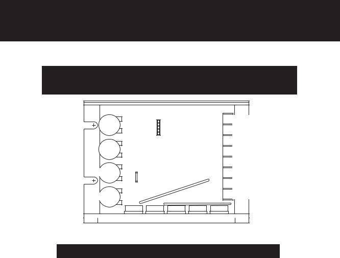
123D/125D HOOK-UP DIAGRAM
Warning:
Do not attempt to perform Hi-pot test across AC lines with control in circuit.
This will result in immediate or long term damage to the control.
MIN |
P2 |
ADDER BOARD |
|
|
CONNECTOR |
MAX |
|
IR COMP |
P3 |
|
INHIBIT |
|
PIN |
CUR LIM
P1
-8 SPEEDPOT LO (orange lead)
-7 SPEEDPOT WIPER (red lead)
-6 SPEEDPOT HI (white lead)
-5 + FIELD
-4 -ARMATURE / - FIELD
-3 + ARMATURE
-2 VAC INPUT (N) -1 VAC INPUT (L)
CONTROL START-UP
WARNING: ALL POWER MUST BE TURNED OFF BEFORE PROCEEDING!
1.Recheck all wiring. Accidental grounds, loose or pinched wires on armature or speedpot wires may damage the control when
power is applied.
2.Check to see that incoming service is of correct voltage.
3.Turn speedpot to zero (fully CCW).
4.Turn power on, and advance speedpot while observing motor. Power must be off before step 5 can be accomplished!
5. If motor rotation is incorrect, turn power off at external disconnect and reverse +ARM and -ARM connections.
6.Check for satisfactory operation throughout the speed range.
7.If operation is satisfactory, no readjustments are needed.
8. If instability or surging is observed, or if maximum speed is higher than desired, see "TRIMPOT ADJUSTMENT CHART " on page 5.
9. For other problems, consult page 10, “IN CASE OF DIFFICULTY”.
4
 Loading...