


®
Operating
Instructions
 CAUTION: To reduce the risk of injury, the user must read and understand this instruction manual before using this product. Save these instructions for future reference.
Table of Contents
The Darex Story .................................................................................... |
page 2 |
Safety Instructions ............................................................................... |
page 3 |
XT-3000 Specification Sheet................................................................. |
page 5 |
Capabilities & Performance .................................................................. |
page 6 |
XT-3000 Reference Drawing................................................................. |
page 7 |
Setting Up the XT3000.......................................................................... |
page 8 |
Drill Alignment...................................................................................... |
page 9 |
Drill Sharpening .................................................................................... |
page 12 |
Drill Point Splitting ............................................................................... |
page 14 |
Chuck Information................................................................................ |
page 16 |
Wheel Information................................................................................ |
page 18 |
General Maintenance ............................................................................ |
page 21 |
Trouble Shooting Section...................................................................... |
page 24 |
Drill Nomenclature................................................................................ |
page 25 |
Wiring Diagram..................................................................................... |
page 26 |
Electrical Diagram................................................................................. |
page 27 |
Chuck Parts List .................................................................................... |
page 28 |
Exploded View - Chuck ......................................................................... |
page 29 |
Parts List - Machine Rev B Serial Number ............................................ |
page 30 |
Exploded View - Machine Rev B Serial Number .................................... |
page 31 |
Exploded View - Sharpening Fixture 118°-150° (All Models)............... |
page 32 |
Exploded View - Alignment Schematic Rev B Serial Number................ |
page 33 |
Parts List - Machine Rev A Serial Number ............................................ |
page 34 |
Exploded View - Machine Rev A Serial Number .................................... |
page 35 |
Exploded View - Alignment Schematic Rev A Serial Number................ |
page 36 |
LEX050 - Large Drill Attachment .......................................................... |
page 39 |
LEX100 - XY Table Attachment ............................................................. |
page 43 |
LEX150 - Countersink Attachment........................................................ |
page 44 |
LEX200 - Brad Point Attachment .......................................................... |
page 48 |
LEX250 - Step Drill Attachment ............................................................ |
page 50 |
LEX300 - 90º - 120º Drill Attachment................................................... |
page 54 |
LEX350 & 351 - Mini Attachment........................................................... |
page 58 |
XT3000 Auto Sharpener Attachment..................................................... |
page 61 |
*For Technical Service visit our web site at www.darex.com |
|
Or call Darex 800-547-0222 |
|
Or contact your Darex Distributor |
|
3
The Darex Story
Darex Corporation began in 1973 in Beecher, Illinois. The D, A and R of Darex are the initials of three generations of the Bernard family; David, Arthur and Richard Bernard. David and his father Richard founded Darex. Grandfather Arthur Bernard, who earlier founded the Bernard Welding Company, contributed his energy and guidance to Darex. Art’s inventions revolutionized the welding industry.
In 1978, Darex relocated to Ashland, Oregon. Grandson Dave and son Dick carry on Arthur’s legacy of inventiveness. Darex grew to become the most recognized name in the cutting tool sharpening industry. Today, Darex is a world-leading manufacturer of precision cutting tool sharpeners.
Darex is proud to offer a complete line of quality precision cutting tool sharpeners at affordable prices. Before our first days, we at Darex had looked at our competitor’s sharpeners and asked ourselves: “Must cutting tool sharpeners be complicated? Why must the choice be limited to cost prohibitive accuracy or low price inaccuracy?” Our sharpeners prove you can have it all: Simplicity, Accuracy, and Affordability.
We have always emphasized innovative product design and tested technology. The experienced personnel at our modern manufacturing facility use the latest production methods. The Darex marketing team knows first-hand the machines we sell and will guide you to the best machine for your needs. Our skilled technical service department is happy to answer your questions about our products or cutting tools.
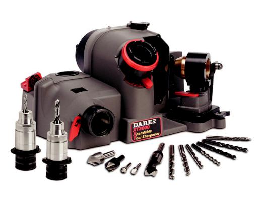
The XT-3000 Sharpener
The Darex XT-3000 Xpandable Drill Sharpener sharpens standard and split point drills at any angle from 118 to 150 degrees. It sharpens drills sized from 3mm to 21mm. (.118 - .826) This sharpener comes standard with CBN wheels for sharpening HSS and cobalt drills. Diamond wheels for sharpening carbide drills are available as an option. The XT-3000 allows you to control each drill’s point configuration including the relief and design of the split point. All adjustment and attachment changes are done without tools. To keep your Darex XT-3000 in top condition, please refer to the maintenance section of this manual.
Replacement wheels and parts are listed in the parts list on page 30. Schematic breakdowns begin on page 31 of the manual.
*Optional accessories allow you to sharpen other cutting tools; including 90° spot drills, step drills, brad points, larger drills, Weldon, single flute, 3 flute, 6 flute countersinks and left hand drills.
2

Safety Instructions
|
|
|
|
|
|
Safety Instructions |
• |
NEVER LEAVE TOOL RUNNING |
|
|
|
|
|
FOR YOUR OWN SAFETY, READ INSTRUCTION |
|
UNATTENDED Turn power off. |
|
|
|
|
|
|
• |
USE PROPER EXTENSION CORD Make sure |
||
|
|
|
|
|
|
MANUAL BEFORE OPERATING MACHINE! |
||
|
|
|
Caution: |
|
extension cord is in good condition. When using |
|||
|
|
|
|
|
• |
WE DO NOT RECOMMEND OPERATING |
|
an extension cord be sure to use one heavy |
|
|
|
|
|
|
MACHINE WITHOUT A VACUUM SYSTEM |
|
enough to carry the current the Drill Sharpener |
|
|
|
|
|
• |
RUNNING |
|
will draw. An undersize cord will cause a drop in |
|
|
|
|
|
GRINDING DUST INHALED/INGESTED |
|
line voltage, resulting in a loss of power and/or |
|
|
|
|
|
|
• |
CAN BE HARMFUL TO YOUR HEALTH. |
• |
overheating. |
|
|
|
|
|
GRINDING PARTIALS WILL CAUSE |
DO NOT USE DAMAGED OR UNSHAPED |
||
|
|
|
|
|
|
DAMAGE TO THE INTERNAL |
|
WHEELS Use grinding wheels suitable for speed |
|
|
|
|
|
|
COMPONENTS |
• |
of grinder. |
|
|
|
Caution: |
THE CONTINUOUS A-WEIGHTED sound |
||||
|
|
|
WHEN USING ELECTRIC TOOLS, BASIC SAFETY |
|
pressure level at the operator’s ear is not over |
|||
|
|
|
PRECAUTIONS SHOULD ALWAYS BE FOLLOWED |
• |
60dB (A). |
|||
|
|
|
TO PREVENT THE RISK OF FIRE, ELECTRIC |
RISK OF INJURY DUE TO ACCIDENTAL |
||||
|
|
|
SHOCK AND PERSONAL INJURY, INCLUDING |
|
STARTING. Do not use in an area where |
|||
|
|
|
THE FOLLOWING: |
• |
children may be present. |
|||
|
|
|
|
|
• |
WHEN MAINTENANCE OR MACHINE |
THE WEIGHTED ROOT MEAN SQUARE |
|
|
|
|
|
|
|
ADJUSTMENTS ARE PERFORMED ON |
|
ACCELERATION VALUE to which the arms are |
|
|
|
|
|
|
SHARPENER ALWAYS: Push the emergency |
• |
subjected to does not exceed 2.5 m/s2. |
|
|
|
|
|
|
stop button, unplug unit from power supply |
WARNING: This product contains a chemical |
|
|
|
|
|
|
|
and use a “LOCK OUT” “TAG OUT” procedure. |
|
known to the State of California to cause cancer. |
|
|
|
|
|
• |
FOLLOW INSTRUCTIONS ENTITLED |
|
Some dust created by power sanding and grinding |
|
|
|
|
|
|
“DAREX XT-3000 Maintenance" in this |
|
as well as contents from the machine may contain |
|
|
|
|
|
|
Instruction Manual. |
|
chemicals known to the State of California to cause |
|
|
|
|
|
• NEVER TOUCH INTERNAL PARTS OF THE |
|
||
|
|
|
|
|
|
cancer, birth defects or other reproductive harm. |
||
|
|
|
|
|
|
SHARPENER WHEN THE SHARPENER IS |
|
|
|
|
|
|
|
|
ON The rotating grinding wheel can cause |
|
|
|
|
|
|
|
|
injury. |
|
|
|
|
|
|
|
• USE CAUTION WHEN REPLACING THE |
|
|
|
|
|
|
|
|
|
GRINDING WHEEL Follow instructions |
|
|
|
|
|
|
|
|
entitled “How to change a wheel”, on page 18 |
|
|
|
|
|
|
|
|
of this Instruction Manual. |
|
|
|
|
|
|
|
• KEEP GUARDS IN PLACE and in working |
|
|
|
|
|
|
|
|
|
order. See Decal at left. |
|
|
|
|
|
|
|
• REMOVE WRENCHES Always check to see |
|
|
|
|
|
|
|
|
|
that any tools have been removed from |
|
|
|
|
|
|
|
|
sharpener before turning it on. |
|
|
|
|
|
|
|
• KEEP WORK AREA CLEAN Cluttered areas |
|
|
|
|
|
|
|
|
|
and benches invite accidents. |
|
|
|
|
|
|
|
• DON'T USE IN DANGEROUS |
|
|
|
|
|
|
|
|
|
ENVIRONMENT Do not use power tools in |
|
|
|
|
|
|
|
|
damp or wet locations, or expose them to rain. |
|
|
|
|
|
|
|
|
Do not use tools in the presence of flammable |
|
|
|
|
|
|
|
|
liquids or gases. |
|
|
|
|
|
|
|
• KEEP WORK AREA WELL LIT |
|
|
|
|
|
|
|
|
• |
STORE EQUIPMENT in a safe place when not |
|
|
|
|
|
|
|
|
in use. |
|
|
|
|
|
|
|
• DON'T FORCE TOOL It will do the job better |
|
|
|
|
|
|
|
|
|
and safer at the rate for which it was designed. |
|
|
|
|
|
|
|
• USE THE RIGHT TOOL Don’t force tool or |
|
|
|
|
|
|
|
|
|
attachment to do a job it was not designed for. |
|
|
|
|
|
|
|
• TO MINIMIZE THE RISK OF INJURY, ALWAYS |
|
|
|
|
|
|
|
|
|
USE PROPER EYE AND REPIRATORY PROTECTION: |
|
|
|
|
|
|
|
|
Everyday eyeglasses only have impact resistance lenses |
|
|
|
|
|
|
|
|
and they are NOT safety glasses. (See Decal at left.) |
|
|
|
|
|
|
|
|
Use appropriate respiratory face or dust mask. |
|
|
|
|
|
|
|
• AVOID ACCIDENTAL STARTING Make sure |
|
|
|
|
|
|
|
|
|
switch is in the “OFF" position before plugging |
|
|
|
|
|
|
|
|
it in. |
|
|
|
|
|
|
|
• |
USE RECOMMENDED ACCESSORIES |
|
|
|
|
|
|
|
|
|
||
|
|
|
|
|
|
|
||
|
|
|
|
|
|
Consult the owner's manual for recommended |
|
|
|
|
|
|
|
|
|
|
|
|
|
|
|
|
|
|
|
|
230v~,50Hz,6A |
|
accessories. The use of improper accessories |
|
|
||||
|
|
|
|
|
|
may cause hazards. See Decal at left. |
|
|
|
|
|
|
|
• CHECK FOR DAMAGED PARTS Before |
|
|
|
|
|
|
|
|
|
further use of the tool, a guard or other part |
|
|
|
|
|
|
|
|
that is damaged should be carefully checked to |
|
|
|
|
|
|
|
|
|
|
|
|
|
|
|
|
|
|
|
|
|
|
|
|
|
|
assure that it will operate properly and perform |
|
|
|
|
|
|
|
|
|
|
|
230v~,50Hz,8A |
|
its intended function. Check for alignment of |
|
|
||||
|
|
|
|
|
|
moving parts, binding of moving parts, |
|
|
|
|
|
|
|
|
breakage of parts, mounting and any other |
|
|
|
|
|
|
|
|
|
|
|
|
|
|
|
|
|
conditions that may affect its operation. A |
|
|
|
|
|
|
|
|
guard or other part that is damaged should be |
|
|
|
|
|
|
|
|
properly repaired or replaced. |
|
|
3

GROUNDING INSTRUCTIONS
•FOR ALL GROUNDED CORD CONNECTED TOOLS:
•In the event of a malfunction or breakdown, grounding provides a path of least resistance for electric current to reduce the risk of electric shock. This tool is equipped with an electric cord having an equipment-grounding conductor and a grounding plug. The plug must be plugged into a matching outlet that is properly installed and grounded in accordance with all local codes and ordinances. Do not modify the plug provided if it will not fit the outlet, have the proper outlet installed by a qualified electrician. Improper connection of the equipment-grounding conductor can result in a risk of electric shock. The conductor with insulation, having an outer surface that is green with or without yellow stripes, is the equipment-grounding conductor. If repair or replacement of the electric cord or plug is necessary, do not connect the equipmentgrounding conductor to a live terminal. Check with a qualified electrician or serviceman if the grounding instructions are not completely understood, or if in doubt as to whether the tool is properly grounded. Use only 3-wire extension cords that have 3-prong grounding plugs and 3- pole receptacles that accept the tool’s plug. Repair or replace damaged or worn cord immediately.
•GROUNDED, CORD-CONNECTED TOOLS INTENDED FOR USE ON A SUPPLY CIRCUIT HAVING A NOMINAL RATING LESS THAN 250 VOLTS: See Table 1 for minimum gauge cords.
Table 1 Minimum Gauge Cords
|
|
Volts |
Total length of cord (feet / meters) |
|||
|
|
120 V |
25 / 7.5 |
50 / 15 |
100 / 30 |
150 / 45 |
Ampere Rating |
240 V |
50 / 15 |
100 / 30 |
200 / 60 |
300 / 90 |
|
M ore than |
Not more than |
|
|
AWG |
|
|
0 |
6 |
|
18 |
16 |
16 |
14 |
6 |
10 |
|
18 |
16 |
14 |
12 |
10 |
12 |
|
16 |
16 |
14 |
12 |
12 |
16 |
|
14 |
12 |
Not Recommended |
|
4
XT-3000 Specification Sheet
XT-3000
DRILL SHARPENER
XT-3000 Features
The XT-3000 was designed incorporating Versatility, Simplicity & Expandability. Optional attachments sharpen other cutting tools including step drills, brad points, larger drills, Weldon and single flute countersinks. This unit is an upgrade-able sharpener that grows with your needs. Simplicity will allow multiple users successful results with minimal training.
Specifications for 115V & 230V
·Standard Grinding Wheels: 180 Grit CBN - HSS, Cobalt & 180 Grit Diamond - Carbide
· |
Max Wheel Diameter: |
6.45 inch ( 164 mm) |
|
|
· |
Arbor Size: |
1.25 inch (31.75 mm) |
|
|
· |
Wheel Surface Speed: |
75 ft/sec (23m/sec) for 60 Hz |
Model 115V |
|
|
Motor Specs: |
95 ft/sec (29m/sec) for 50 Hz |
Model 230V |
|
· |
¼ hp - 2850 rpm – 60 Hz |
Model 115V |
||
|
Operating Time: |
¼ hp - 3450 rpm – 50 Hz |
Model 230V |
|
· |
Continuous Duty |
|
||
· |
Voltage: |
115 VAC +/- 10% & 230 VAC +/- 5% |
||
· |
Frequency: |
60 Hz +/- 5% - |
Model 115V |
|
|
Sharpener Current: |
50 Hz +/- 5% - |
Model 230V |
|
· |
2.5A |
Run / 40A Start |
Model 115V |
|
|
Accessory Current: |
1.6A |
Run / 25A Start |
Model 230V |
· |
6.0A |
Run Max. |
|
|
·Operating Temperature: 40° to 95° F ambient (4° to 35° C)
. Humidity: |
Non-condensing |
5

Capabilities & Performance
Capabilities & Performance
• |
Drill Types: |
Two fluted HSS, Cobalt or Carbide SAE & Metric twist drills |
• |
Drill Point Styles: |
Standard Conic & Split Point |
• |
Split Point Styles: |
Standard X split |
• |
Point Angles: |
118° - 150° |
• |
Drill Diameter: |
3 mm - 21 mm (.118 to .826) |
•Lip Height Accuracy: ANSI B94.11, NAS 907 and ISO 10899 Standards
Decal Identifications
“Wear Safety Glasses” -
115v~,50Hz,6A
Accessory receptacle capacity -
115v~,50Hz,8A
“Do not operate without wheel guard cover” -
6

XT-3000 Reference Drawing
230V Units Only
7
Setting up the XT3000
The XT-3000 comes equipped with grinding wheels, a sharpening fixture and 2 chucks, 1; 3mm – 12mm & 1; 12mm
–21mm.
1.Remove from shipping box and all packaging material before powering up the machine. NOTE: Due to the weight of the XT-3000, it is suggested that the lip of the casting, located above the motor, can be used as a handle for lifting.
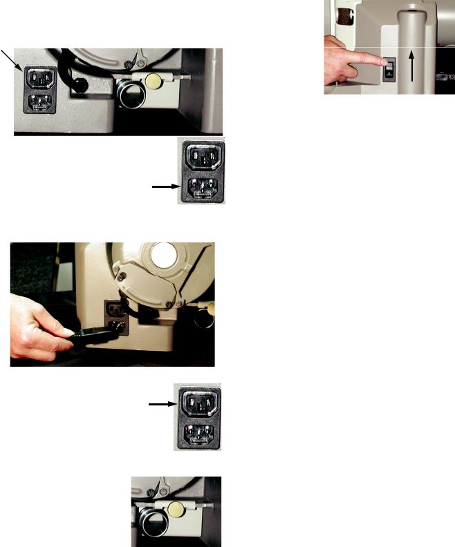
2.Located at the back and on the right side of the XT3000 is the power receptacle. Within that receptacle you will find a power inlet and accessory receptacle.
3.The power inlet is located at the bottom of the power receptacle.
Plug the power cord in to the power inlet and then in to the power outlet source.
4. The accessory receptacle is located at the top of the power receptacle and will allow you to use a dust extraction system in conjunction with the use of the XT3000.
*We highly recommend the use of a vacuum when the machine is in use. Darex offers a vacuum system compatible
with your XT3000. Call Darex for more information.
•SA12075EA - 115V
•SA12072EA - 230V
5.Make sure the grit tray is in place and secure.
6.Un-box the chucks.
7.Make sure sharpening fixture is secured to base. For more information on mounting the sharpening fixture. See
page 12.
8.To power on the machine, push the rocker switch to the ON position to start the grinding wheel in motion.
9.To sharpen a drill follow steps in the next three sections; Align, Sharpen and Point Splitting.
8
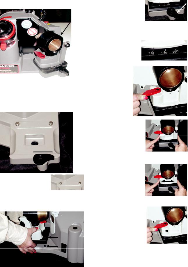
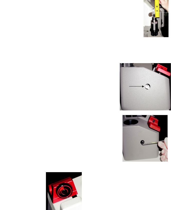
Drill Alignment
The alignment port is located on the left side of the XT-3000.
or counterclockwise to increase material removal.
The first stage to sharpening a drill starts with the alignment process. In the alignment process, you will go through a few necessary steps prior to sharpening. Setting the material removal amount, adjusting the alignment tube to produce desired relief amount. Use the Darex easy align to set the drill to length and time the cutting edge.
Setting Material Removal
Amount


 1. Rotate the material removal

 knob to adjust the amount of
stock you want to remove from the end of the drill. Stock
removal ranges from approximately .010 -
.030. Remove more material if the drill is excessively worn or damaged. Remove less material if you are
renewing the drill.
2. Rotate the material removal knob clockwise to decrease the amount of material removal
Tip:
Sharpen drills
on Minimum MTO to achieve longer wheel life.
Setting Alignment Tube for Desired Heel Relief
135° |
118° |
To increase or decrease the amount of heel relief produced during sharpening, change the position of the alignment tube.
1. Lift the alignment locking lever.
This will allow you to rotate
the alignment tube in either direction. 2. To increase heel relief, rotate the alignment tube counterclockwise.
135° |
118° |
|
9 |
Drill Alignment |
|
|
|
To decrease heel relief, rotate clockwise. |
2. |
Rotate the chuck knob clockwise, which |
|
|
|
|
closes the chuck jaws onto the drill. Then |
|
|
|
slightly loosen the chuck jaws by rotating |
|
|
|
the chuck knob counterclockwise, about ½ |
135° |
118° |
|
turn. To determine how tightly the drill |
|
|
|
should be held during the alignment |
|
|
|
process, the drill should slide freely and |
|
|
|
drop out when the chuck is held in a |
|
|
|
vertical position. |
|
|
|
Timing the cutting edge |
3. To secure the alignment position, |
3. |
Insert the |
|
chuck and drill |
tighten locking |
into the |
|
lever. |
||
alignment tube. |
||
|
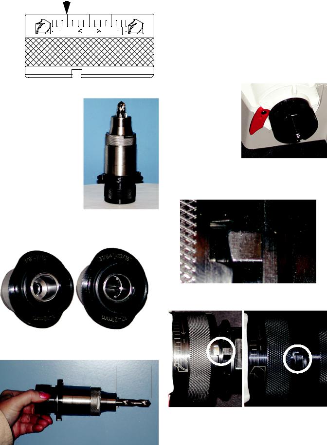
Setting the drill to the proper length
Align the cam dogs with the slots.
1.Holding the chuck in a horizontal
position insert the drill into the appropriate sized chuck. (Sizes are on the cam)
The cam dogs should bottom out against the slots.
Allow the drill to protrude approximately 2 inches as shown.
 2”
2” 
10
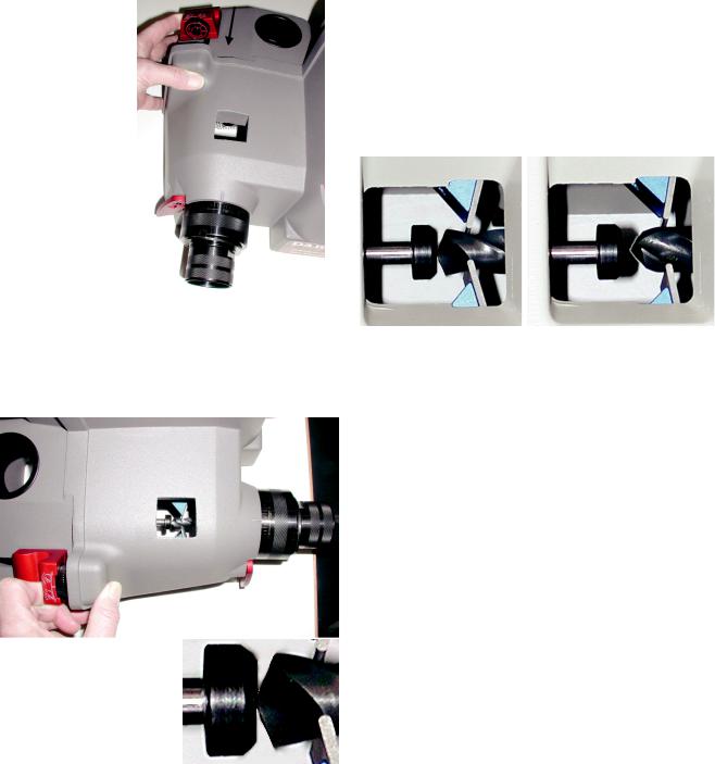
4.S-L-O-W-L-Y squeeze together the red slide handle until it touches casting. We emphasize slowly, because squeezing the handles too quickly pushes the drill too deeply into the chuck.
NOTE: If this happens, the drill will not touch the wheel during the sharpening process.
5.With the handles held together, look through the viewing port and see if drill is
positioned correctly.
Drill point should be touching the end of the pusher shaft cap.
Drill Alignment
The pawls should be seated in the helix of the drill. If incorrect, loosen chuck knob and repeat step 4. The jaws are most likely gripping the drill body too tightly and will not allow the drill to rotate into position.
CORRECT INCORRECT
6.Once the drill has been aligned correctly and without releasing the slide handle, tighten the chuck knob clockwise until the chuck jaws grip the drill securely. Release the slide handle and remove chuck from alignment tube.
11
Drill Sharpening
The Sharpening fixture is located on the right side of the machine.
3.After sharpening fixture is in place, rotate the locking lever clockwise until snug. This will secure the fixture to the base.
Adjusting the Point Angle
You must loosen the sharpening fixture and slide the point angle indicator to the desired degree.
Mounting the Sharpening fixture |
1. To loosen, pull |
1. Rotate the locking lever so the flat edge is at |
the locking |
lever towards |
|
the top, horizontal and in a straight line with |
you. |
the base casting. |
|
2.Position the sharpening fixture so that the 2 location holes on the
base of the alignment fixture are aligned with the 3/8 dowel pins.
2.Place fingers on each side of the sharpening pivot base casting.
3.Gently slide base casting in either direction to align
the angle indicator with the desired point angle degree.
4.Secure the selected point angle position by pushing the locking lever away from you
until it stops.
5.Before sharpening, make sure the sharpening fixture is secure and no longer slides in either direction.
12

Drill sharpening
WARNING: Make sure Split Port Cover and Eye Shield are in place before sharpening. (International Models Only)
2.Insert the chuck with the thickest part of the cam touching the swing bearing.
Power up machine
To turn the machine on, push the top of the rocker switch. The machine will power up and the grinding wheels will begin to rotate.
Sharpen
1.To make sure the drill clears the wheel, push the sharpening tube all the way to the left before inserting chuck.
3.Release sharpening tube very slowly.
4.With slight pressure towards the grinding wheel, rotate the chuck 360 degrees, several times in a clockwise direction. To achieve an efficient and balanced sharpening on both cutting
edges, avoid stopping when the drill is in the grind. Do not reposition your hand in mid-sharpening, wait until the drill rotates off the wheel. Continue rotating the chuck in 360 degree rotations until the grinding noise is minimized to a near silence.
5.Before removing the chuck, push the sharpening tube to the left, remove chuck. Release sharpening tube slowly.
13

Drill Point Splitting
The Point Splitting Port is located in the center of the machine.
Approximately 3-7° rake is created, producing a drill with a self-centering point. Its advantages are the ability to reduce thrust and eliminate walking at the drill point. This is a distinct advantage where drill bushings/fixtures are not used.
Splitting
POINT SPLIT DIAGRAMS
DEPTH OF SPLIT DIAGRAM
Past Center |
To Center |
Below Center |
Upon completion of the sharpening procedure, Do Not loosen the drill in the chuck. Insert the chuck into the point splitting port. Align the cam dogs with the slots on the point split
tube. Let the weight of the chuck ease the drill down and onto the grinding wheel. With slight pressure, be sure the chuck stays seated in the point splitter.
When the grinding noise is reduced to near silence pull the chuck out about 1/2 way and rotate it 180 degrees to split the opposite side of the drill
point.
NOTE: Do not force the chuck into the grinding wheel or damage to the drill or wheel may occur.
Adjusting the Depth of Split
The depth of split can vary from drill manufacturer to drill manufacturer. The point split depth adjustment
feature designed on the XT-3000 makes it easy to mimic multiple split styles. The point split depth adjustment lever is attached to the point split chuck tube. As you
move the lever, it backs the chuck tube away from the wheel or moves it
closer into it.
1.Located on the underside of the point splitter is the point split depth adjustment lever.
2.To increase the depth of split, push lever to the left toward the + sign.
This will allow the drill to travel deeper into the wheel, increasing the depth of split.
3.To decrease the depth of split, push the lever to the right toward the – sign. This will back the
drill away from the wheel.
NOTE: To correct a drill that has been split deeper than desired, you will have to regrind the drill beyond the over split portion before splitting again.
14
Drill Point Splitting
POINT SPLIT ANGLE
DIAGRAM
split angle adjuster |
118° 135° |
clockwise to increase the split angle.
3.Rotate the adjuster
counter clockwise |
118° |
135° |
to decrease the split angle.
4.Once split angle adjustment has been made, rotate the point split nut clockwise to retain the selected setting and secure the point split angle adjuster.
Adjusting the Split Angle Rotation
Typically the split angle of a drill is 120° - 130° from the cutting edge. By increasing the rotation of the split angle, the split portion of the drill meets the cutting lip at a greater angle, which will give the drill more strength and durability. This added split angle creates a pointed profile at the very center of the drill, producing a selfcentering effect and reduces drill point walking at the start of a hole.
1.Loosen the point split nut by rotating the nut counterclockwise.
2.Rotate the point
15
Chuck Information
A regular maintenance program should be set up for each chuck. Keeping your chuck clean and grit free will help
maintain drill concentricity and lengthen the life of your chucks. For detailed cleaning instruction, See Maintenance page 22.
XT-3000 CHUCKS
The XT-3000 jaw chuck system was designed with accuracy and simplicity in mind. As a result, the XT-3000 chuck allows you to cover a large diameter range of drills without the aid of individual collets. You can quickly change from the largest drill diameter to the smallest in seconds. The accuracy of the chuck will produce drills that exceed ANSI, NAS 907 & & ISO 10899 standards. The various chucks and accessories have drill diameter capabilities that range
from .059” – 1.1875” (1.5mm to 30mm).
Make sure large drills are secure after tightening the chuck.
Morse Taper drills:
To secure a Morse Taper drill in the chuck, it is necessary for the drill to have a minimum flute length of 4.000 inches. The taper will then be free from the grasp of the jaws, eliminating interference with the larger tapered shank. The other option for holding these types of drills is a split bushing. Bush the body of the drill up to or larger than the interfering diameter.
End Mill shank drills:
Typically, an end mill drill has a shank diameter larger than the body of the drill.
Some End Mill shank drills can be sharpened on the XT-3000, depending on the length of the flute verses the length of the shank.
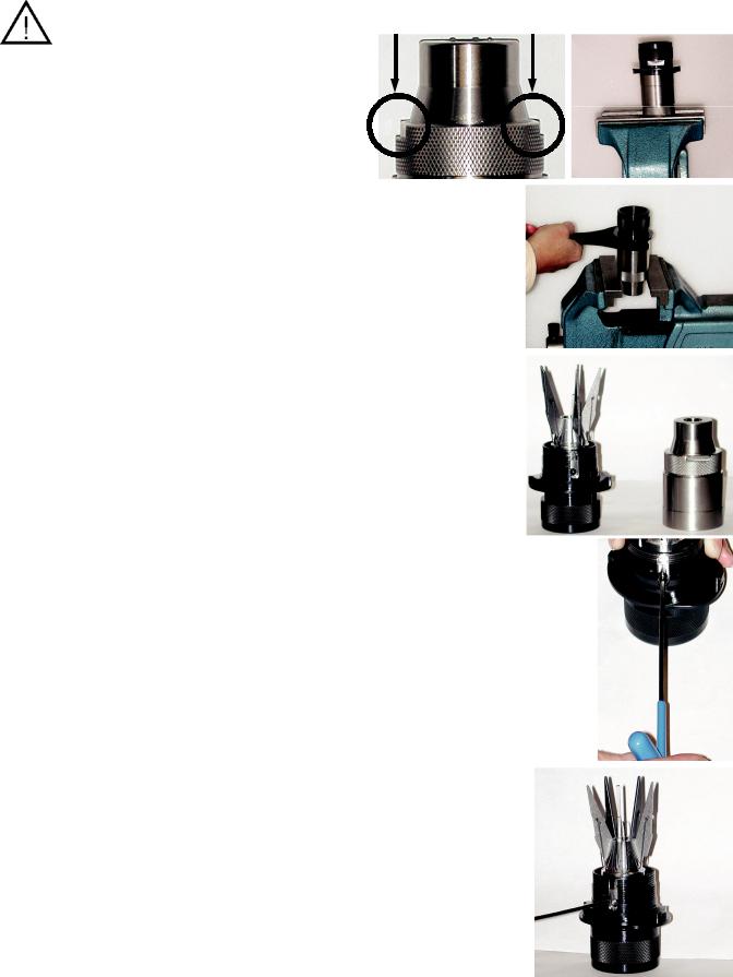
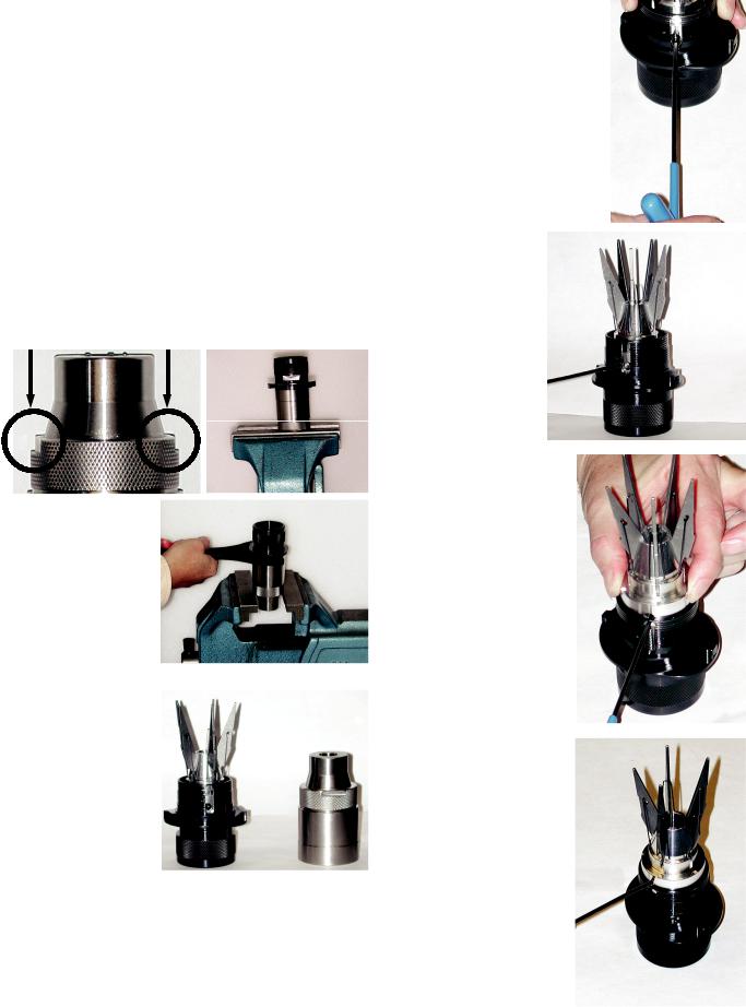
CHUCK DISASSEMBLY &
MAINTENANCE
The use of a dust extraction system during grinding will help reduce the amount of maintenance, however, the
chuck assembly should be disassembled and cleaned periodically. We recommend the
Darex dust extraction system.
1. Place flats of chuck body into a vice, do not
over tighten.
2.Place chuck wrench, PP16480SF, (optional) on dogs of chuck knob assembly.
Rotate wrench counterclockwise to remove chuck knob/jaw assembly from chuck body.
3.Using a 2.5 mm hex wrench remove set screw.
4.The internal pieces must remain keyed, in order to remove the closing screw from the chuck knob assembly. Insert the 2.5
mm wrench into the set screw hole.
16

Chuck Information
5.Rotate chuck knob counter clockwise until the wrench reaches the top of the slot.
6.Remove wrench and reinsert into the set screw hole above the slot.
7. Rotate the chuck knob counterclockwise until the closing screw exits the knob assembly.
8.The chuck knob assembly does not come apart from this point.
TO REASSEMBLE:
Reassemble in reverse order.
CHUCK DESCRIPTIONS AND PART #’S
SA16400TA - 3-12 mm |
Standard Chuck |
SA16450TA - 12-21mm |
Standard Chuck |
SA16500TA - 21-30mm |
Large Drill Chuck |
SA16975TA - 3-12mm |
Step Drill Chuck |
SA16980TA - 12-21mm |
Step Drill Chuck |
SA16890TA - 3-12mm |
90° Chuck |
SA16880TA - 12-21mm |
90° Chuck |
SA16916TA - 3-12mm |
Brad Point Chuck |
SA16918TA - 12-21mm |
Brad Point Chuck |
SA16484TA - 3-12mm |
Left Hand Chuck |
SA16488TA - 12-21mm |
Left Hand Chuck |
SA16401TA - 1.5-7mm |
1.5-7mm Chuck |
SA17010TA - 3-12mm |
Auto Geared Chuck 3-12mm |
SA17025TA - 12-21mm |
Auto Geared Chuck 12-21mm |
17

XT-3000 WHEEL INFORMATION
The Darex XT-3000 comes equipped with electroplated CBN (Cubic Boron Nitride). Optional Diamond wheels are available. The wheel comes installed on your sharpener ready to sharpen drills.
Sharpening with an electroplated CBN (Cubic Boron Nitride) or Diamond grinding wheel reduces grinding cost and improves quality of the finished product. These results are obtained because the grinding material is super abrasive. The CBN is second only to diamond in hardness. In fact, CBN has twice the hardness and four times the abrasion resistance of an aluminum oxide grinding wheel. The CBN and Diamond wheel last longer; the grinding process is faster and less grinding time is lost due to wheel breakdown & maintenance.
WHEEL MAINTENANCE
These wheels are maintenance free from truing and dressing but will need to be cleaned periodically. Disconnect the power from the machine using a lock out tag out procedure. After removing the wheel from the sharpener, saturate the wheel with any type of oil-less solvent, such as Automotive Brake Cleaner. It is helpful to use a soft bristle brush and lightly brush the saturated wheel, loosening the impacted grinding particles. Re-saturate the wheel to flush out any loosened debris. Do not use any type of dressing tool on these wheels. Damage to surface will occur and greatly shorten the wheel life.
NOTE: If after cleaning wheel, the drills still discolor or burn, the wheel life may be exhausted and the wheel will need to be replaced.
WHEEL DESCRIPTIONS AND
PART#’S
•PP16050GF – 180-grit CBN grinding wheel
•PP16060GF – 100-grit CBN Point Split grinding wheel
•PP16052GF – 180-grit Diamond grinding wheel
•PP16062GF – 260-grit Diamond Point Split grinding wheel
•PP16070TF – Grind wheel retainer
Do not attempt to grind carbide drills with CBN wheels. Diamond wheels
are available if carbide is to be sharpened on this machine.
WHEN TO REPLACE THE
WHEEL?
Eventually, the long-life electroplated wheel in your XT-3000 will wear out. Indicators that a wheel change is necessary are: a drop in performance such as drill burning or excessively slow sharpening time. Inspect the wheel for abrasive quality. A worn wheel will appear smooth. If it is necessary, replace the worn wheel(s). New wheels will initially produce a coarser grind. However, this aggressiveness will disappear after approximately the first one hundred drill sharpenings. Under normal use, you should experience 4-6 thousand drill sharpenings from each new wheel.
*Darex does not re-plate or recommend replating the grinding wheels. For replacement wheels, contact your Darex distributor or Darex .
HOW TO CHANGE A WHEEL
1.Unplug unit from power supply and use a “LOCK OUT” “TAG OUT” procedure.
2.Using a 3mm hex key, remove 3; 3mm socket head cap screws (PP12240FF) from wheel guard cover.
18
Wheel Information
3.Pull wheel guard cover away from wheel.
4.Using a 4 mm hex key, remove 3; 5mm socket head cap
screws (PP16318FF) & split washer (PP08650FF)
from grinding wheel retainer.
5.Remove the wheel retainer.
6.Pull wheel toward you then to the right and out of the machine cavity.
7. |
Clean the machine cavity as well as the |
|
mounting hub and wheel before |
|
reinstalling. |
8.Repeat steps in reverse to install new wheel.
NOTE: Because the Darex grinding wheel cannot be trued it is critical that the motor hub & wheel register be cleaned. Once wheel has been installed, rotate the wheel by hand to check that the wheels run true. If not, loosen the screws , reposition the wheel and tighten the screws.
Separating grinding wheel from point split wheel
The grinding and point split wheel are piggy backed and bolted together. To change any one of the wheels you must first separate them. You can access the bolts from the back side of the sharpening wheel.
1.Using a 5mm hex key, remove the 3; 6mm socket head cap screws
(PP16348FF) & split washers.(PP07013FF)
2.The two wheels can now be separated.
Recalibrating Material Removal
After a wheel change, verify and/or recalibrate material removal.
Use a 3/8 HSS standard twist drill, measure the length of drill before sharpening.
1.Rotate material removal knob to maximum take off.
2.Align drill as
though you intend to sharpen it. Follow Alignment steps on page 9.
3.Once drill is set to length, aligned and captured in the chuck securely, remove from alignment port.
19
4.Measure the amount of drill protruding from the end of the chuck to the tip of the drill.
5.The length of the drill protruding from the top of the chuck should measure .970-.980 (24.63 mm - 24.89 mm)
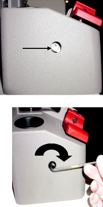
Calibrating the Material
removal knob
1.At the rear of the machine base there is a small
access hole.
2.Insert a
3/16 Allen wrench into the access hole.
3.To advance the pusher shaft cap, reducing the amount of drill stick out, rotate the wrench clockwise.
4.To retract the pusher shaft cap, increasing the
amount of drill stick out, rotate the wrench counterclockwise.
Each ¼ turn will adjust .010 (.25 mm) or one full turn will adjust .04 (1.0 mm) After adjusting the pusher shaft assembly, realign the drill and re-measure the amount of stick out. Repeat the steps 1-4 until the drill protrudes .970-.980 in length. (24.63 mm - 24.89 mm)
Wheel Information
At the Minimum material removal setting, approximately .005 (.127mm) should be removed from the end of the drill.
20
GENERAL MAINTENANCE
To extend the life of your sharpener, we recommend a routine maintenance program be put in place. Every 120-machine hrs is suggested, or
more often if necessary.
WARNING: Remove the plug before carrying out any adjustment, servicing or maintenance.
Vacuum system:
Optional but recommended.
Using a dust extraction system can improve the sharpening life of the machine. Unplug vacuum from power source. Check filter or canister on a regular basis.
Wheel cleaning:
These wheels are maintenance free from truing and dressing but will need cleaned periodically. After removing the wheel from the unit, saturate the wheel with any type of oil-less solvent, such as Automotive Brake Cleaner. It is helpful to use a soft bristle brush and lightly brush the saturated wheel, loosening the impacted grinding particles. Re-saturate the wheel to flush out any loosened debris.
Always clean a brand new wheel before using.
If after cleaning wheel, the drills still discolor or burn, the wheel life may be exhausted and the wheel will need to be replaced.
Recalibrating Material Removal
After a wheel change, verify and/or recalibrate material removal.
Use a 3/8 HSS standard twist drill, measure the length of drill before sharpening.
1.Rotate material removal knob to maximum take off.
2.Align drill as though you intend to sharpen it. Follow Alignment steps on page 9.
3.Once drill is set to
length, aligned and captured in the chuck, securely remove from alignment port.
4.Measure the amount of drill protruding from the end of the chuck to the tip of the drill, before sharpening.
5.The length of the drill protruding from the top of the chuck should
measure .970-.980 (24.63 mm - 24.89 mm)
Calibrating the Material removal knob
1.Located at the rear of the machine base, you will find a small access hole.
2.Insert a 3/16 Allen wrench into the access hole.
3.To advance the pusher shaft cap, reducing the amount of drill stick out, rotate the wrench clockwise.
4.To retract the pusher shaft cap, increasing the amount of drill stick out, rotate the wrench counterclockwise.
Each ¼ turn will adjust .010 (.25 mm) or one full turn will adjust .04 (1.0 mm). After adjusting the pusher shaft assembly, realign the drill and re-measure the amount of stick out. Repeat the steps 1-4 until the drill protrudes .970-.980 in length. (24.63 mm - 24.89 mm)
21
General Maintenance
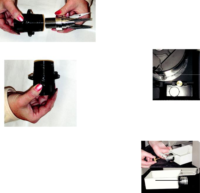
Chuck Maintenance
Chuck maintenance is very important. To sustain the life of your chucks and to maintain precision lip height concentricity, clean the chucks on a regular basis. Some tools are necessary to disassemble the chuck, You will need: Wrench PP16480SF (Optional)
4. Using a 2.5 mm hex wrench, remove set screw.
Disassembly:
The use of a dust extraction system while grinding will help reduce the amount of maintenance necessary, however, periodically the chuck assembly should be disassembled and cleaned.
1. Place flats of chuck body into a vice.
2.Place chuck wrench on dogs of chuck knob assembly.
3.Rotate wrench counterclockwise to remove chuck knob/jaw assembly from chuck body.
5.The internal pieces must remain keyed in order to remove the closing screw from the chuck knob assembly. Insert the 2.5 mm wrench, into the set screw hole.
6.Rotate chuck knob counterclockwise until the wrench reaches the top of the slot.
7.Remove wrench and reinsert into the set screw hole above the slot.
22
8. Rotate the chuck knob counterclockwise until the closing screw exits the knob assembly.
9. The chuck knob assembly does not come apart from this point.
Chuck Cleaning:
Once disassembled, clean all parts with a type of oil-less solvent such as Automotive Break Cleaner.
Chuck Re-assembly:
Reassemble in reverse order.
Point Split Tube Cavity:
Routinely vacuum and using a dry cloth, wipe out the inside of the Point Split Tube. Removing grinding dust will help produce consistent split point drills by retaining the ID dimensions of the tube and reducing early wear.
Sharpening Tube Cavity:
Using a dry cloth, wipe out the inside of the brass tube, removing grinding dust. Over time it may be necessary to replace the sharpening tube. The sharpening tube is threaded into the housing using right-handed threads. To remove, rotate tube counterclockwise using a spanner wrench. Replace as needed.
General Maintenance
Wheel Housing Cavity:
While grinding wheel is out of machine and before replacing wheel, vacuum out wheel housing and wipe around the hub area.
External Machine Castings:
Wipe down external machine castings with a mild household cleaner.
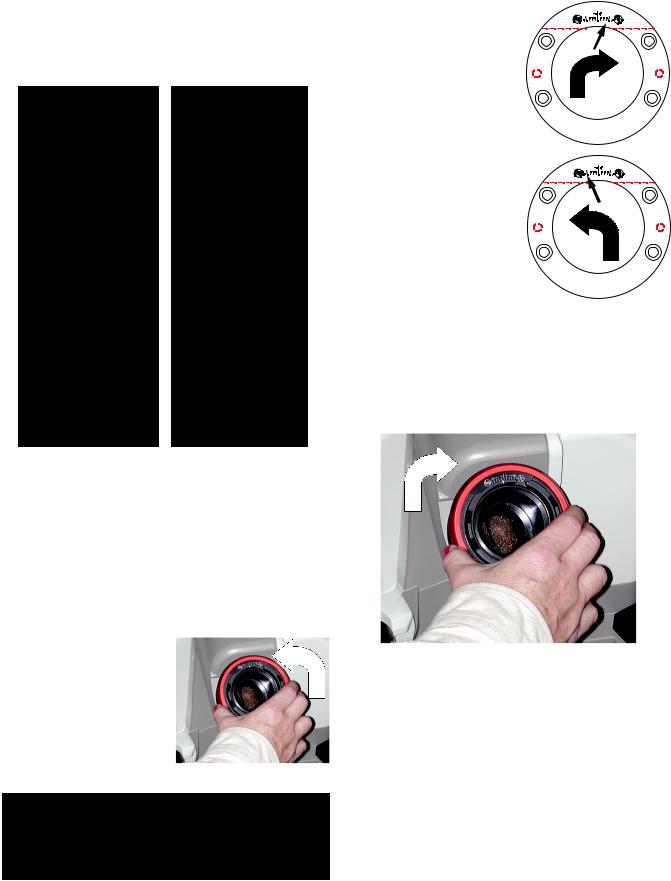
Grit Tray/Vacuum Port Connection: Grit tray
At the back of the machine, located underneath the grinding motor is the grit tray. Drill grindings will accumulate inside the grit tray. The grit tray has a magnetic liner to attract and hold these dust particles. Do
not let the tray become more than 1/3 full. To remove tray, unscrew brass thumb screw. Remove tray and dump contents. Wipe excess dust from the tray with a rag.
Vacuum Port Connector (Optional)
The grit tray has a knock out plug that can be removed by hand and replaced with the vacuum tube (SA16030TA).
Use this port to connect a vacuum
hose to the
XT3000. This method of extracting dust particles from the machine will keep it cleaner and is recommended.
Oil Lubrication:
Never use an oil-based lubricant on any part of this machine! Oil-based lubricant will collect grinding dust particles. Powdered graphite may be applied to any sliding parts located on the machine.
23
Trouble Shooting XT-3000 Drill Sharpening
Symptom
Using ON/OFF switch does not work
Machine won’t power up
Cause
•No power at outlet
•Make sure power cord is plugged in to machine and outlet
•Release e-stop (230v machine only)
•E-stop nut is loose and stuck down in the off position (230v machine only)
•On/off switch needs to be replaced
•Wiring lead disconnected
•Grinding wheel obstructed and can’t rotate
•Grinding motor bad
Symptom
Tip of drills burn or discolor
Cause
•Wheel needs to be cleaned
•Material take off too aggressive
•Wheel needs to be replaced
Symptom
Unable to secure drill in or release drill
from chuck
Cause
•Tapered shank drill
•The drill may have a slight taper to the body
•Shank of drill larger than body
•Drill has multiple diameters that are interfering with jaws
•Incorrect drill diameter for that particular chuck
•Drill flutes are damaged or have burrs
•Chuck needs to be cleaned
Symptom
Drill incorrectly split
Cause
•Check settings on the split point fixture
•Did not align correctly
•Point Split Tube calibration is off
Symptom
Material take off varies
Cause
•Wheel not secure to motor hub
•Wheel calibration is off after new wheel change
•Cam dog not properly seated in alignment slot during alignment set up
•Drill is pushing back in the chuck during grinding
•Operator is not sparking drill out
Symptom
No material take off during grinding
Cause
•Drill loose in chuck
•Drill tip not touching the pusher shaft cap during alignment process
Symptom
Length of time drill is in the grind becomes
excessive
Cause
•Material take off too excessive
•Grinding wheel needs to be cleaned
•Grinding wheel needs to be replaced
Symptom
Lip height concentricity is out of tolerance
Cause
•Material take off too excessive
•Chuck needs to be cleaned
•Sharpening tube needs to be cleaned
•Chuck is worn out and needs to be replaced
•Sharpening tube is worn and needs to be replaced
•Wheel is not running true
24

|
Drill Nomenclature |
DRILL NOMENCLATURE |
|
FACET & CONIC DRILL STYLE |
POINT SPLIT |
PICTURE AND |
DEPTH OF SPLIT DIAGRAM |
NOMENCLATURE |
|
CENTER OF SPLIT DIAGRAM
POINT SPLIT ANGLE DIAGRAM
CONIC DRILL
120° |
95 |
° |
130° |
||
|
10 |
5° |
CLEARANCE
Facet Diagram (re-sharpen on the XPS16)
FACET DRILL
RELIEF
25
 Loading...