


®

Table of Contents
The Darex Story ......................................................................... |
Page 3 |
Safety Instructions ..................................................................... |
Page 4 |
Cautions .................................................................................... |
Page 6 |
XPS-16 Specification Sheet .......................................................... |
Page 9 |
Capabilities & Performance .......................................................... |
Page 10 |
Machine Axis Definition ................................................................ |
Page 11 |
Touch Screen Icon Reference ...................................................... |
Page 13 |
Sharpening Your First Drill ........................................................... |
Page 17 |
Touch Screen Details .................................................................. |
Page 19 |
Custom Drill Geometry Section .................................................... |
Page 35 |
Cutting Edge Advance Screen ....................................................... |
Page 39 |
Download Details ........................................................................ |
Page 41 |
Chuck Information Standard & Collet Style ..................................... |
Page 47 |
Honing Information ..................................................................... |
Page 53 |
Vacuum System Information ......................................................... |
Page 55 |
Wheel Information ....................................................................... |
Page 57 |
Sharpening Tips .......................................................................... |
Page 61 |
Trouble Shooting Section .............................................................. |
Page 63 |
Drill Nomenclature ....................................................................... |
Page 73 |
Sample Drill File Form .................................................................. |
Page 75 |
Drill Style Recommender ............................................................. |
Page 77 |
General Maintenance ................................................................... |
Page 79 |
Machine & Vacuum Parts List w/Exploded Views ............................. |
Page 83 |
Electronics, Wiring diagrams, Service Parts Replacement Instruction |
|
& Exploded Views ........................................................................ |
Page 91 |
*For Technical Service visit our web site at www.darex.com
Or call Darex 800-547-0222
PP12850KF - User Manual
3

The Darex Story
The Darex Story
Darex Corporation began in 1973 in Beecher, Illinois. The D, A and R of Darex are the initials of three generations of the Bernard family; David, Arthur and Richard Bernard. David and his father Richard founded Darex. Grandfather Arthur Bernard, who earlier founded the Bernard Welding Company, contributed his energy and guidance to Darex. Art’s inventions revolutionized the welding industry.
In 1978, Darex relocated to Ashland, Oregon. Grandson Dave and son Dick carry on Arthur’s legacy of inventiveness. Darex grew to become the most recognized name in the cutting tool sharpening industry. Today, Darex is a world-leading manufacturer of precision cutting tool sharpeners.
Darex is proud to offer a complete line of quality precision cutting tool sharpeners at affordable prices. Before our first days, we at Darex had looked at our competitor’s sharpeners and asked ourselves: “Must cutting tool sharpeners be complicated? Why must the choice be limited to cost prohibitive accuracy or low price inaccuracy?” Our sharpeners prove you can have it all: Simplicity, Accuracy, and Affordability.
We have always emphasized innovative product design and tested technology. The experienced personnel at our modern manufacturing facility use the latest production methods. The Darex marketing team knows first-hand the machines we sell and will guide you to the best machine for your needs. Our skilled technical service department is happy to answer your questions about our products or cutting tools.
The XPS-16 CNC Sharpener
The Darex XPS-16 CNC Drill Sharpener can be programmed to sharpen an infinite variety of conical, four-facet, split-point and/or radius split point drills. The XPS-16 can sharpen HSS and carbide twist drills from 1/8” to 5/8” (3- 16 mm) diameter, 2” to 8 ¾” long, and angles of 90 to 150 degrees. Memory stores user-defined drill point geometries. In a single set-up the Darex XPS-16 automatically sizes, aligns, then sharpens the drill and splits the point and can hone the drill’s cutting edges to minimize chipping. Benefits include: Convenient internal chuck holds drill; LCD screen display panel for one-touch programming; Long-lasting super-abrasive plated grinding wheels; “Grind Motion Control” monitors load on the grinding wheel; adjusts feed and speeds keeping drills cool, diagnostic software alerts operators of potential problems.
To keep your Darex XPS-16 in top condition, please refer to the maintenance section of this manual. Replacement wheels and parts are listed in the parts list on page 83 & 84. A schematic breakdown of the machine is on page 85 of the manual.
3

Safety Instructions
Safety Instructions
GROUNDING INSTRUCTIONS
•For all grounded, cord connected tools:
•In the event of a malfunction or breakdown, grounding provides a path of least resistance for electric current to reduce the risk of electric shock. This tool is equipped with an electric cord having an equipment-grounding conductor and a grounding plug. The plug must be plugged into a matching outlet that is properly installed and grounded in accordance with all local codes and ordinances. Do not modify the plug provided-if it will not fit the outlet, have the proper outlet installed by a qualified electrician. Improper connection of the equipment-grounding conductor can result in a risk of electric shock. The conductor with insulation, having an outer surface that is green with or without yellow stripes, is the equipment-grounding conductor. If repair or replacement of the electric cord or plug is necessary, do not connect the equipment-grounding conductor to a live terminal. Check with a qualified electrician or serviceman if the grounding instructions are not completely understood, or if in doubt as to whether the tool is properly grounded. Use only 3-wire extension cords that have 3-prong grounding plugs and 3-pole receptacles that accept the tool’s plug. Repair or replace damaged or worn cord immediately. See Table 1. Minimum Gauge Cords below.
•Grounded, cord-connected tools intended for use on a supply circuit having a nominal rating less than 150 volts:
This tool is intended for use on a circuit that has an outlet that looks like the one illustrated in Figure A. The tool has a grounding plug that looks like the plug illustrated in Figure A. A temporary adapter which looks like the adapter illustrated in Figures B and C, may be used (except in Canada) to connect this plug to a 2-pole receptacle as shown in Figure B if a properly grounded outlet is not available. The temporary adapter should be used only until a qualified electrician can install a properly grounded outlet. The green colored rigid ear lug, etc. extending from the adapter must be connected to a permanent ground such as a properly grounded outlet box. See Fig. 1. Grounding methods below.
•Grounded cord-connected tools intended for use on a supply circuit having a nominal rating between 150-250 volts inclusive: See Table 1. Minimum Gauge Cords below.
Table 1 Minimum Gauge Cords
Fig .1 |
|
|
|
(A) |
|
(B) |
|
(D) |
|||||
|
|
|
|
|
|
|
|
(C) |
|
||||
|
|
|
|
|
|
|
|
|
|
||||
Grounding |
|
|
|
|
|
|
|
|
|
|
|
|
|
methods |
|
|
|
|
|
|
|
|
|
|
|
|
|
|
|
|
|
|
|
|
|
|
|
|
|
|
|
|
|
|
|
|
|
|
|
|
|
|
|
|
|
|
|
|
|
|
|
|
|
|
|
|
|
|
|
|
|
|
|
|
|
|
|
|
|
Metal |
|
Grounded |
Grounding Pin |
|
|
|
|
|
|
|
Cover of |
|
|||||
|
|
|
|
|
|
|
|
|
Screw |
|
Means |
|
|
|
|
Grounding Pin |
|
|
grounded |
|
|
|
|
||||
|
|
|
|
|
|
|
|
|
|
||||
|
|
|
|
outlet box |
|
|
|
|
|
|
|||
|
|
|
|
|
|
|
|
|
|
|
|
|
|
|
|
|
|
|
|
|
|
|
|
|
|
|
|
|
|
|
|
|
|
|
|
|
|
|
|
|
|
4

Safety Instructions
FOR YOUR OWN SAFETY, READ INSTRUCTION MANUAL BEFORE OPERATING MACHINE!
Caution:
DO NOT OPERATE MACHINE WITHOUT VACUUM SYSTEM RUNNING
Airflow from vacuum cools grinding motor
Grinding dust inhaled/ingested can be harmful to your health
Grinding particles will cause damage to th e internal components
Caution:
WHEN USING ELECTRIC TOOLS, BASIC SAFETY PRECAUTIONS SHOULD ALWAYS BE FOLLOWED TO PREVENT THE RISK OF FIRE, ELECTRIC SHOCK AND PERSONAL INJURY, INCLUDING THE FOLLOWING:
WHEN MAINTENANCE IS PERFORMED ON SHARPENER ALWAYS: Push the emergency stop button, unplug unit from
power supply and use a “LOCK OUT” “TAG OUT” procedure.
Follow instructions entitled “DAREX XPS-16 Maintenance" in this Instruction Manual.
Never touch internal parts of the sharpener when the sharpener is on. The rotating grinding wheel can cause injury.
Use caution when replacing the grinding wheel. Follow instructions entitled “Replacing The Grinding Wheel”, in this
Instruction Manual.
KEEP GUARDS IN PLACE and in working order.
REMOVE WRENCHES and Adjusting Keys Always check to see that any tools have been removed from the sharpener before turning it on.
KEEP WORK AREA CLEAN Cluttered areas and benches invite
accidents.
DON'T USE IN DANGEROUS ENVIRONMENT Do not use
power tools in damp or wet locations, or expose them to rain. STORE EQUIPMENT in a safe place when not in use.
DON'T FORCE TOOL It will do the job better and safer at the
rate for which it was designed.
USE THE RIGHT TOOL Don’t force tool or attachment to do a job it was not designed for.
ALWAYS USE SAFETY GLASSES TO MINIMIZE THE RISK OF INJURY, ALWAYS USE PROPER EYE AND RESPIRATORY
PROTECTION: Everyday eyeglasses only have impact resistance lenses and they are NOT safety glasses. (See Decal at left.) Use appropriate respiratory face or dust mask.
MAINTAIN TOOL WITH CARE Keep tools sharp and clean for
best and safest performance.
DISCONNECT TOOLS from the power supply before service or when changing accessories .
AVOID ACCIDENTAL STARTING Make sure switch is in the
“OFF" position before plugging cord in to outlet or machine.
USE RECOMMENDED ACCESSORIES Consult the owner's manual for recommended accessories. The use of improper
accessories may cause hazards.
CHECK FOR DAMAGED PARTS Before further use of the tool, a guard or other part that is dama ged should be carefully checked to assure that it will operate properly and perform its intended function. Check for alignment of moving parts, binding of moving parts, breakage of parts, mounting and any other conditions that may affect its operation. A guard or other part that is damaged
should be properly repaired or replaced.
NEVER LEAVE TOOL RUNNING UNATTENDED Turn power
off.
USE PROPER EXTENSION CORD Make sure extension cord is in good condition. When using an extension cord be sure to use one heavy enough to carry the current the Drill Sharpener will draw. An undersize cord will cause a drop in line voltage, resulting
in a loss of power and/or overheating.
DO NOT USE DAMAGED OR UNSHAPED WHEELS Use
Safety Instructions
grinding wheels suitable for speed of grinder
NEVER STAND ON TOOL
USE ONLY FLANGES (OR WASHERS) FURNISHED WITH TOOL
THE CONTINUOUS A-WEIGHTED sound pressure level at
the operator’s ear is not over 60dB (A)
RISK OF INJURY DUE TO ACCIDENTAL STARTING.
Do not use in an area where children may be present.
THE WEIGHTED ROOT MEAN SQUARE ACCELERATION VALUE to which the arms are subjected to does not exceed
2.5 m/s
KEEP CHILDREN AWAY. All visitors should be kept a safe distance from work area.
MAKE WORKSHOP KID PROOF with padlocks, master switches, or by removing starter keys.
WEAR PROPER APPAREL. Do not wear loose clothings, neckties, rings, bracelets, or other jewlery which may get caught in moving parts. Nonslip footware is recommended. Wear protective hair covering to contain long hair.
DON'T OVERREACH. Keep proper footing and balance at all times.
WARNING: This product contains a chemical known to the State of California to cause cancer. Some dust created by power sanding and grinding as well as contents from the machine may contain chemicals known to the State of California to cause cancer, birth defects or other reproductive harm.
5

Cautions
CAUTION
Do not operate machine without using vacuum system
•Grinding dust inhaled/ingested can be harmful to your health
•Grinding particles can cause damage or erratic operation of the sharpener
•Airflow from vacuum cools the grinding wheel & motor during sharpening
Do not alter length of vacuum hose
Remove wheel before cleaning
Do not operate machine in adverse environmental conditions
•Minimum 7°C (45°F) Maximum 32°C (90°F)
Do not remove jaws from springs OR springs from spindle insert
•Jaws are positioned and then match ground. By disassembling you will compromise the concentricity. Refer to information on page 47
Do not interrupt or shut down sharpening machine while in the lube cycle
•Remove drill from chuck before pressing the Check icon to continue lube process
Do not interrupt or shut down sharpening machine while downloading software
Use a Diamond wheel to grind carbide drills
•Grinding carbide on a CBN wheel will cause damage to the wheel
Use grounding straps and static dissipating materials when handling electronics
Do not pinch, bend or crimp the Fiber optic cable
•The thin black cable, can be found underneath the left side of the top cover, fastened to the top of the spindle cartridge block
Do not over tighten chuck when securing drill
•May cause chuck to lock up
Do not replace interior lamp with substitute bulb
•Damage or erratic operation could result.
6
Material Safety Data Sheet
US DEPARTMENT OF LABOR |
Form Approved Occupational Safety and Health |
|||
|
|
Administration |
|
0MB No 44-Ri 367 |
|
|
MATERIAL SAFETY DATA SHEET |
|
|
Required under |
USDLThisSafetypage& H althwasRegulintentionallytionsfor Ship Repairing,leftShipblankuilding.and |
Chip breaking |
|
|
|
|
129 CFR 1915, 1916.19171 |
|
|
SECTION I
MANUFACTURERS NAME: Professional Tool Mfg LLC EMERGENCY PHONE NO: (541) 488-2224
ADDRESS: 210 E. Hersey Street, Ashland, Oregon 97520
CHEMICAL NAME & SYNONYMS Diazon-Electroplated Diamond/CBN Products, Diamond (uncoated)
Man-Made Diamond. RVG. MBG. MBS Product Families. Standard Series and 300 Series Diamond Micron Powder TRADE NAME & SYNONYMS: Electroplated CBN Wheels, Electroplated Diamond Wheels
CHEMICAL FAMILY: Abrasive Any Grade FORMULA: n/a
|
SECTION II COMPOSITION |
|
|
CHEMICAL NAME |
Nickel |
Industrial Diamond |
|
REGULATED |
Yes |
No |
|
CAS#: |
7440-02-0 |
7882-40-3 |
|
AGIH TLV |
1 0 mgm3 |
10.0 mg m3 (PNOC) |
|
CARCINOGEN |
Yes |
No |
|
Materials are regulated by OSHA 29 CFR 1910.1200, Hazard Communication Standard |
|
||
SECTION III - PHYSICAL AND CHEMICAL DATA |
|
||
BOILING POINT (F) |
n/a |
MELTING POINT |
n/a |
SPECIFIC GRAVITY |
n/a |
VAPOR PRESSURE |
n/a |
VAPOR DENSITY |
n/a |
EVAPORATION RATE |
n/a |
SOLUBILITY IN WATER |
n/a |
SOLUBILITY IN ALCOHOL |
n/a |
|
|
SOLUBILITY IN OTHER SOLVENT |
n/a |
|
|
PERCENT VOLATILE BY VOLUME (%) |
n/a |
APPEARANCE AND ODOR Solid, Clear, White To Yellow To Dark Crystals Silver Color. |
|
||
SECTION IV - FIRE AND EXPLOSION HAZARD DATA |
|
||
FLASH POINT |
n/a |
|
|
(METHOD USED) |
FLAMMABLE LIMITS |
LEL |
UEL |
EXTINGUISHING MEDIA |
|
n/a |
|
SPECIAL FIRE FIGHTING PROCEDURES: |
|
n/a |
|
UNUSUAL FIRE AND EXPLOSION HAZARDS: |
|
n/a |
|
SECTION V - HEALTH, FIRST AID AND MEDICAL DATA
PRIMARY ROUTE(S) OF ENTRY: Inhalation, Ingestion, Skin, Eye(s)
EFFECTS OF OVEREXPOSURE
INHALATION: Difficulty in breathing (Dust from wheel use).
INGESTION: If a dust, symptoms are variable.
SKIN: Irritation (especially if sensitive to Ni ).
EYE(S): Irritation (from Ni or diamond particle).
FIRST AID AND MEDICAL INFORMATION:
INHALATION: Move to fresh air. Give oxygen if necessary
INGESTION: Obtain medical attention.
SKIN: Wash thoroughly with water Obtain medical help if necessary
EYE(S): Flush thoroughly with water. Obtain medical assistance
OTHER POTENTIAL HEALTH RISKS
Nickel (Ni) is listed as a carcinogen Avoid long exposure. Consult medical personnel for first aid and medical information
SECTION VI - CORROSIVELY AND REACTIVITY DATA
STABILITY: |
|
Unstable ( ) |
Stable (x) |
POLYMERIZATION: |
|
May occur ( ) |
Will not occur (x) |
INCOMPATIBILITY: |
(Materials to avoid) |
|
n/a |
HAZARDOUS COMPOSITIONS PRODUCTS: |
|
n/a |
|
CONDITIONS TO BE AVOIDED: Contact with strong acids/caustics, enclosed areas.
SECTION VII - SPILL, LEAK AND DISPOSAL PROCEDURES
STEPS TO BE TAKEN IN CASE MATERIAL IS RELEASED OR SPILLED: Normal clean up procedure
WASTE DISPOSAL METHOD:
Waste will contain nickel. Dispose in accordance with all applicable Federal, state, and local regulations.
SECTION VIII – PERSONAL PROTECTION INFORMATION
RESPIRATORY PROTECTION:
Respiratory protection as needed see OSHA-29 CFR 1910.134
VENTILATION: LOCAL EXHAUST: strongly preferred
MECHANICAL (GENERAL): Use only if adequate to maintain below TLV’s. PROTECTIVE GLOVES: As desired by user.
EYE PROTECTION: Recommended see OSHA29 CFR 11910.215
OTHER PROTECTIVE EQUIPMENT: Use standard precautions for grinding operations.
SECTION IX - STORAGE AND HANDLING PROCEDURES
NORMAL STORAGE AND HANDLING:
Store in clean, dry area, away from chemicals.
NORMAL USE: Use adequate ventilation (See Section VIII )
7

This page was intentionally left blank.
8
XPS-16 Specification Sheet
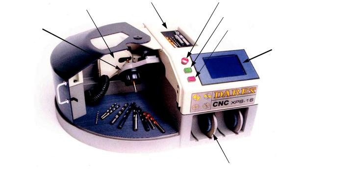
CNC XPS-16
DRILL SHARPENER
|
|
|
|
DRILL HOLDER |
|
EMERGENCY STOP |
||||
|
WHEEL GUARD COVER |
|
|
|||||||
|
|
|
|
|
|
|
|
|
||
|
|
|
|
|
|
|
||||
|
CYCLE START |
|
|
|||||||
|
|
|
|
|
|
|
|
|
||
|
|
|
|
|
|
|
|
|
|
|
|
CHUCK |
|
|
|
|
|
|
|
||
|
|
CYCLE STOP |
|
|||||||
|
|
|
|
|
|
|
|
|
||
|
|
|
|
|
|
|
|
|
|
|
LCD TOUCH SCREEN
DOOR 
 GRIND WHEEL STORAGE
GRIND WHEEL
XPS-16 Auto Measurement Features
Your XPS-16 has many features so carefully designed and engineered that you may not even be aware of their uniqueness. Once the cycle start button has been pushed, your Darex XPS-16 begins taking measurements of the drill, on the way to the grinding wheel. Your XPS-16 locates the end of the drill, calculates diameter, locates and positions the cutting edge, determines web thickness, identifies initial contact point of drill to the wheel and then sharpens. After sharpening and before splitting the drill, your XPS-16 sharpener again measures and re-locates the end of the drill, ensuring an accurate split.
Specifications
• Standard Grinding Wheels: 180 Grit CBN - HSS, Cobalt & 220 Grit DIA - Carbide
•Operating temperature: Not less than 7°C (45°F) or more than 32°C (90° F)
• |
Motor Specs: |
BLDC motor 115/230 V RPM 3800-3900 50/60 hz |
• |
Power requirements: |
8 amp @ 115 V; 4 amp @ 230 V |
•Machine Dimensions: 66cm W x 56cm D x 30.5cm H (26” W x 22” D x 12” H)
• Machine Weight: |
52 kg (115lbs) |
•Shipping Dimension: 78cm W x 89cm D x 45cm H (31” W x 35” D x 18” H)
•Vacuum Dimensions: 36cm D x 49cm H (14” D x 18” H)
• |
Vacuum Weight: |
14 kg (30lbs) |
• |
Total Ship Weight: |
66 kg (145lbs) |
• |
Warranty: |
1 year defective parts and labor |
9
Capabilities & Performance
Capabilities & Performance
•Drill Types: Two fluted HSS, Cobalt or Carbide SAE & Metric twist drills
•Point Styles: Four Facet & Standard Conic points
•Split Point Styles: Standard X split and Radius split
• |
Point Angles: |
90° - 150° |
• |
Drill Diameter: |
3mm - 16mm (.118 to .629) |
• |
Drill Length |
50.8mm - 222.3mm (2” to 8.750) |
|
|
Tolerances |
•Lip Height Accuracy: ANSI B94.11, NAS 907 and ISO 10899 Standards
•Point Angle: 90° - 150° with a tolerance of +/- 2°
• Relief: |
5° - 18° margin relief with a tolerance of +/- 2° |
•Split Angle: 120° - 170° with a tolerance of +/- 5°
• Fan Angle: |
Tolerance of +/- 15° |
Approximate Grinding Performance Times using drills with a standard web thickness
Material |
Point |
Diameter |
MTO |
Relief |
Hone |
*Grind |
*Grind |
|
Angle |
(inch) |
(inch) |
(Degree) |
Time |
Times: |
Times: |
|
(Degree) |
|
|
|
(sec) |
No Split |
X-Split |
|
|
|
|
|
|
|
|
HSS |
118° |
.125 |
.005 |
11° |
0 |
: 36 |
: 56 |
|
|
|
|
|
|
|
|
HSS |
118° |
.375 |
.005 |
9° |
0 |
: 45 |
1:13 |
|
|
|
|
|
|
|
|
HSS |
118° |
.625 |
.005 |
7° |
0 |
: 49 |
1:25 |
|
|
|
|
|
|
|
|
|
|
|
|
|
|
|
|
CARBIDE |
135° |
.125 |
.006 |
11° |
1 |
: 44 |
1:08 |
|
|
|
|
|
|
|
|
CARBIDE |
135° |
.375 |
.006 |
9° |
3 |
: 58 |
1:30 |
|
|
|
|
|
|
|
|
CARBIDE |
135° |
.625 |
.005 |
7° |
5 |
1:16 |
1:59 |
|
|
|
|
|
|
|
|
*Approximate |
|
|
|
|
|
|
|
grind times |
|
|
|
|
|
|
|
based on using |
|
|
|
|
|
|
|
a new grinding |
|
|
|
|
|
|
|
wheel |
|
|
|
|
|
|
|
10
Machine Axis Definition
Machine Axis Definition
11

Machine Axis Definition
Machine Axis definition
12

Touch Screen Icon Reference
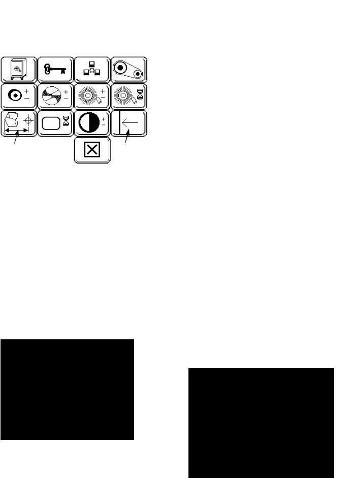
TOUCH SCREEN ICON REFERENCE
For more information on Icons refer to the Touch Screen Details section pages 19 to 34
CYCLE START (GREEN) Refer to information on page 32
CYCLE STOP (AMBER) Refer to information on page 32
CONTINUE
STOP or EXIT
HOME - SHUT DOWN/RETURN TO
Refer to information on page 32
MAIN SET UP SCREEN ICONS
POINT ANGLE SELECTION SCREEN
Refer to information on page 19
MINIMUM MATERIAL REMOVAL Refer to information on page 20
MID RANGE MATERIAL REMOVAL Refer to information on page 20
MAXIMUM MATERIAL REMOVAL Refer to information on page 20
DIAMETER DETECTION SCREEN Refer to information on page 20
WEB THICKNESS DETECTION SCREEN Refer to information on page 20
HONE OPTION SELECTED Refer to information on page 21
NO HONE SELECTED Refer to information on page 21
HONE ONLY Refer to information on page 21
NO SPLIT SELECTED Refer to information on page 22
STANDARD SPLIT POINT Refer to information on page 22
RADIUS SPLIT POINT Refer to information on page 22
MARGIN RELIEF SELECTION SCREEN Refer to information on page 22
HIGH SPEED STEEL or COBALT MATERIAL Refer to information on page 23
CARBIDE MATERIAL Refer to information on page 23
FILE MANAGEMENT - TEMPORARYMEMORY Refer to information on page 23
13

Touch Screen Icon Reference
SPLIT POINT OFFSET Refer to information on page 29
TOOLS, OFFSET & MAINTENANCE PAGE Refer to information on page 27
QUICK START SET UP SCREEN
*Found only in software with date code of 70129 or earlier
CONIC GRIND - MAIN SET UP SCREEN AND QUICK START Refer to information on page 25
CONIC STANDARD SPLIT GRIND - QUICK START Refer to information on page 25
FACET GRIND - MAIN SET UP SCREEN AND QUICK START Refer to information on page 25
FACET STANDARD SPLIT GRIND - QUICK START Refer to information on page 25
118-DEGREE POINT ANGLE - QUICK START Refer to information on page 25
135-DEGREE POINT ANGLE - QUICK START Refer to information on page 25
CANCEL AND RETURN TO MAIN SET
UP SCREEN
MAIN SET UP 2ND
LEVEL SCREEN ICONS
“INCHES” - METHOD OF MEASUREMENT Refer to information on page 20
“METRIC” - METHOD OF MEASUREMENT Refer to information on page 20
ADVANCE Refer to information on page 21
AUTO MODE SELECTOR Refer to information on page 20
MANUAL ALIGN KEY Refer to information on page 21
CANCEL KEY
SAVE CHANGES
BACKSPACE WILL ERASE TEXT
TOOLS, OFFSET & MAINTENANCE SCREEN 2ND LEVEL ICONS
SPACE Refer to information on page 24
DELETE FILE KEY Refer to information on page 24
SAVE SCREEN - TO FLASH MEMORY Refer to information on page 27
FILE OPEN Refer to information on page 27
 CURSOR DOWN ARROW
 CURSOR UP ARROW
 PAGE DOWN ARROW PAGE UP ARROW
TO MOVE A MACHINE AXIS IN THE POSITIVE DIRECTION
TO MOVE A MACHINE AXIS IN THE NEGATIVE DIRECTION
HONE TIMING ADJUSTMENT Refer to information on page 31
SCREEN CONTRAST ADJUSTMENT
Refer to information on page 31
TOUCH SCREEN SENSITIVITY ADJUSTMENT Refer to information on page 32
14

HONING WHEEL POSITION OFFSET Refer to information on page 31
HONE BRUSH EDGE OFFSET
HONE BRUSH FACE OFFSET
WHEEL POSITION OFFSET Refer to information on page 28
WHEEL EDGE OFFSET
WHEEL FACE OFFSET
SPLIT POINT OFFSET Refer to information on page 29
DOWN LOAD Refer to information on page 27
UI Update Button (USER INTERFACE)
– From PC to XPS-16 Refer to information on page 41
Controller Update Button – From PC to XPS-16 Refer to information on page 45
Restart machine Refer to information on page 46
BROKEN CONNECTION - DOWN LOAD NOT SUCCESSFUL Refer to information on page 64
Touch Screen Icon Reference
INACCESSIBLE TO CUSTOMER - FOR FACTORY USE ONLY Refer to information on page 27
ALARMS AND MAINTENANCE
CONTROLLER DOWNLOADING WARNING Refer to information on page 45
CUSTOM FILE SAVE OVER WARNING Refer to information on page 24
PAUSE OR CANNOT CONTINUE AT THIS TIME Refer to information on page 41
IN LUBE CYCLE SCREEN Refer to information on page 79
SAVE FILES/SETTINGS - TO PC FROM XPS-16 Refer to information on page 43
OPEN/RESTORE FILES AND SETTING - FROM PC TO XPS-16 Refer to information on page 44
BELT CHANGE Refer to information on page 28
GRINDING WHEEL CHANGE NECESSARY Refer to information on page 23
Z AXIS STAGE BEHIND THE LIMITS Refer to information on page 69
15
Touch Screen Icon Reference
MATERIAL TAKE OFF #1 ALARM
UNABLE TO DETECT END OF DRILL Refer to information on page 63
CUTTING EDGE DETECTION ALARM - UNABLE TO LOCATE CUTTING EDGE Refer to information on page 63
MATERIAL TAKEOFF #2 ALARM Refer to information on page 63
CLOSE DOOR ALARM Refer to page 64
INSERT DRILL ALARM - NO DRILL DETECTED IN CHUCK Refer to information on page 63
REMOVE DRILL ALARM - DRILL LEFT IN CHUCK Refer to information on page 63
Z - AXIS ALARM Refer to information on page 69
C-AXIS ALARM Refer to information on page 64
A-AXIS ALARM Refer to information on page 64
X-AXIS ALARM Refer to information on page 64
GRIND MOTOR ERROR - Refer to information on page 63
WHEEL TIME OUT ERROR Refer to information on page 63
BAD CODE ERROR Refer to information on page 64
Stick-Out/Facet Overlap Adjustment Refer to information on page 38
16

Sharpening Your First Drill
Sharpening Your First Drill
Steps to sharpening your first drill on your CNC XPS16 Drill Sharpener.
Connect vacuum hoses and vacuum power cord to sharpener. Refer to information on page 55
1.Plug in machine and release emergency stop button.
2.Located on the right side of the machine is the ON/OFF rocker switch. To power up machine, push rocker switch up.
3. Touch the  on the LCD Screen; the Self Test Initialization program
will run. After initialization is complete the Main Set Up Screen will come up. Refer to information on page 19
4. Insert a drill in chuck. With the cutting edge rotated in approximately the 12:30 to 1:00 position, push in and hold the tip of drill up against plunger, while tightening chuck to secure drill position. Do not over tighten the chuck.
WARNING: DO NOT USE XPS-16 WITHOUT VACUUM CONNECTED. IN ADDITION TO REMOVING GRINDING PARTICLES, THE AIR FLOW COOLS THE GRINDING MOTOR.
NOTE: The plunger or stop is spring-loaded, drill must push plunger in all the way
5.Using the pictorial icon selections located on the Main Set Up Screen choose your desired drill point geometry. Refer to information on page 19
6.Close machine door.
7. Press cycle start
17

This page was intentionally left blank.
18
Touch Screen Details
Touch Screen Details
Power up the XPS-16 sharpener refer to information on page 17 and connect vacuum system, for details refer to information on page 55
Self Test Initialization Screen
The initialization screen displays important information. On the
first line you will
find the Darex toll free phone number, the 2nd line displays the machine serial #. The 3rd line
has the current User Interface software version followed by the Controller software version. This information is necessary when updating your software or for technical inquiries.
•Remove the drill and touch the “check” on the screen; the Self Test Initialization
program will begin. The machine will begin initialization tests, checking sensors, verifying limit positions, moving and parking the machine at home. After initialization is successful, a screen will
flash listing each test as passed, then immediately transferring to the Main Setup Screen.
•If initialization is unsuccessful, the word FAILED will appear, making continuation impossible. Power down machine, restart and retry initialization. If initialization fails again, Call Darex for assistance.
XPS-16 SHARPENER TOUCH
SCREEN DETAILS
NOTE: If the touch screen remains idle for longer than 6 minutes, the LCD backlight and grinding wheel will shut down, however, the machine will remain powered up. Lightly, touch anyplace on the face of the LCD screen to activate the backlight.
Main Set-up Screen
Point Angle Screen Selector
•Sharpen point angles of *118° to 150°. Touch the “POINT ANGLE SCREEN” Selector, the Point Angle Screen will
appear.
NOTE: Factory default is “118°”.
*For 90° capabilities call Darex.
Point Angle Screen
•Type in desired point angle degree.
NOTE: If you enter a point angle outside the capability range of the sharpener, the setting will default to the closest MIN/MAX point angle degree.
•Use the “BACKSPACE” button to erase information incorrectly entered.
•Touch the “SAVE” button to store and transfer the “New” information to the Main Set-up Screen.
•Selecting “CANCEL” will delete any unsaved data, retrieving the most recently saved information, transferring you back to the Main Set-up Screen.
19

Touch Screen Details
Material Removal Selector
•Each touch of the icon will bring up the next material removal option. You have three choices: MIN, MID or
MAX
Use MIN when touching up your facet and conic ground drills
Use MID when sharpening chipped facet and conic drills
Use MAX when changing point angles or repairing heavily damaged points on conic drills only
MAX grind is not an option when a Facet point style is selected
NOTE: Factory default is “MIN”
SETTING |
APPROXIMATE AMOUNT OF |
|
|
MATERIAL REMOVAL |
|
|
|
|
MIN |
.000 |
- .010 (.254mm) |
|
|
|
MID |
.005 - .015 (.127mm - .381mm) |
|
|
|
|
MAX |
.015 |
-.020 (.381mm - .508mm) |
|
|
|
NOTE: The “MIN/MID/MAX” material removal grind amount is approximate. Point angle, lip relief and point style will cause the material removal amount to vary.
Diameter Screen Selector
•Sharpen drills with a diameter range of .118 -.629 (3mm-16mm). Touch the icon to bring up the Diameter Screen, you have 2 options: Manual or Auto.
NOTE: Factory default is “AUTO” mode.
•When “AUTO” mode is selected, the drill
diameter will be detected automatically as it begins the sharpening cycle. The calculated diameter will be displayed in the diameter selector icon. 
•Entering the drill diameter manually is an option and necessary when the drill being held in the chuck jaws is of a different diameter than that of the drill diameter actually being sharpened. (Example: Step Drill Pilot)
Diameter Selector Screen
•Use the number pad to type in the correct drill diameter, including decimal point. The diameter entered will appear on the
Main Screen Diameter Selector button
and will disable the auto mode.
NOTE: If you enter a drill diameter size outside the capability range of the sharpener, the setting will default to the closest MIN/ MAX diameter size.
•Choose method of measurement, either “inch” or “mm” (metric) . Each touch of this button will toggle between the two
choices. The method of measurement selected is at the top and in slightly larger font is the selected type of measurement and all other numbers will be displayed in that choice of measurement.
•Use the “BACKSPACE” button to erase information incorrectly entered.
•Touch the “SAVE” button to store and transfer the “New” information to the Main Set-up Screen.
•Selecting “CANCEL” will delete any unsaved data, retrieving the most recently saved information, transferring you back to the Main Set-up Screen.
•To exit manual mode, touch the “AUTO” button on the number pad.
Web Thickness
Screen Selector
•Detect Web thickness range from 15% to 45% of the drills diameter or .018 -
.281 (.457mm-7.131mm). Touch the icon to bring up the Web Thickness
Screen, you have 2 options: Manual or Auto.
NOTE: Factory default is “AUTO” mode.
•Sharpen in the “AUTO” mode when creating or regrinding drills with NO split or
X split. A fiber optic sensor will calculate the web thickness as it locates the cutting edge.
•Entering the web thickness manually is necessary when creating or regrinding an R split Refer to page 35 or advancing the cutting
20
edge. Refer to page 39
Web Detection Screen
•To manually input the web thickness, measure thickness of the web of the drill. Measure web thickness across two points of the chisel line with calipers
•Type in web thickness, including decimal point. The web thickness, manually entered, will appear on the
Main Screen “WEB THICKNESS” Selector button and will disable the auto  mode.
mode.
NOTE: If you enter a number outside the capability range of the sharpener, the setting will default to the nearest MIN/MAX web thickness for that specific diameter of drill.
Cutting Edge Advance Button
•Located within the Web Detection Screen is the “ADVANCE” button. Using this feature may be necessary when the drills cutting edge aligns incorrectly. To compensate for incorrect cutting edge alignment, you can
manually advance the cutting edge using the “ADVANCE” button . This may be necessary when sharpening drills with a hooked cutting edge. Refer to page 39
Manual Align Button
•This feature allows you to bypass the
fiber optic sensor alignment process. Measure and enter the web thickness of the drill, if you do not enter the web thickness, the value will default to the minimum web thickness value within that range. If the diameter detec-
tion is in Auto, the web thickness value will default to the minimum once the diameter has been detected. Touch the Auto button in web detection, the Manual Align button will come up. Touch
Save. Align and the web thickness will appear in the icon on the main page. Insert the drill with the cutting edge at 12 o’clock. Tighten chuck & press cycle start.
Touch Screen Details
Hone Selector
•With each touch of the icon you will bring up the next honing option. You have 3
options: Hone, No Hone or Hone Only
NOTE: Factory default is “NO HONE”.
•Select “HONE” when sharpening carbide drills. Honing the carbide cutting edge greatly influences tool life and the accuracy of the finished surface. The length of hone time is adjustable. The longer the
drills cutting edge remains in the honing cycle, the larger the radius produced on the cutting edge. Refer to page 53. Go to the Hone Timing Adjustment Screen in the Tools, Maintenance and Offset screen to make honing time adjustments. Refer to page 31
•Select “NO HONE” when sharpening High Speed Steel or Cobalt drills.
•Select “HONE ONLY” when only honing drills. Grinding and Splitting will be disabled.
Grind Selector
•With each touch of the button you will bring up the next point style option. There are 2 point
style options: Conic or Facet
NOTE: Factory default is “CONIC”.
•“CONIC” – This radial/cone style grind is known as a conventional point and used through out the machine tool industry. A lip clearance of 12° to 15° at the periphery of the drill, increasing constantly toward the center, is considered standard for the average
class of work.
•“FACET” – Multi faceted drill points consist of a separate cutting lip (primary)
and secondary heel clearance (relief) facet. The multi-faceted drill requires 150% less thrust and produces 70% less heat than a conventional drill.
•The width of the primary facet is determined by the thickness of the drills web and cannot be changed. If your drill has a thin web, we do not recommend a facet point style. The width
21
Touch Screen Details
of the primary |
Facet with thin web Facet with thick web |
facet produced |
|
may be very |
|
thin. The |
|
thicker the |
|
web of your |
|
drill, the wider |
|
the primary facet will appear.
Split Point Selector
•With each touch of the icon you will bring up the next split style option. There are
3 split point options: No Split, X- split (Standard) and R- Split. (Radius) The XPS-16 will produce a chisel angle ground to approximately 130°.
NOTE: Factory default is “SPLIT”.
•“NO SPLIT” – Select when reproducing a non-split drill point style.
•“X-SPLIT” – 4° split point rake angle is created, producing a drill with a selfcentering point. Its advantages are the ability to reduce thrust and eliminate walking at the drill point. This is a distinct advantage where drilling bushings/fixtures are not used.
•“R-SPLIT” – The R-split selection is not an option until the web thickness value has been manually entered. Changing the amount of radius and rotation is adjustable. This is done in the Split Point Offset screen . Refer to information on page 35 for details.
•An R-split will produce a drill with a selfcentering point as well as act as a chip breaker producing smaller chips, which can readily be ejected. The radius will assist the flow of chips and reduce chip impaction at the tip of the drill.
Relief Screen Selector
•Select lip relief clearance from 5° to 18° +/-2°. The diameter and the point angle will determine the degrees of
possible relief. See tables below.
NOTE: The degree of relief entered, will appear on the relief selector button on the main screen menu.
POINT ANGLE 118 – 124
DIAMETER |
DEGREES OF RELIEF |
|
|
.118 – .245 |
8 – 18 |
.245 – .370 |
6 – 16 |
|
|
.370 – .495 |
5 – 14 |
|
|
.495 – .625 |
5 – 12 |
|
|
POINT ANGLE 125-134
DIAMETER |
DEGREES OF RELIEF |
|
|
.118 – .245 |
8 – 16 |
|
|
.245 – .370 |
6 – 14 |
|
|
.370 – .495 |
5 – 12 |
|
|
.495 – .625 |
5 – 10 |
|
|
POINT ANGLE 135-144
DIAMETER |
DEGREES OF RELIEF |
|
|
.118 – .245 |
8 –15 |
|
|
.245 – .370 |
6 – 13 |
|
|
.370 – .495 |
5 – 11 |
|
|
.495 – .625 |
5 – 9 |
|
|
POINT ANGLE 145-150 |
|
|
|
DIAMETER |
DEGREES OF RELIEF |
|
|
.118 – .245 |
8 – 14 |
|
|
.245 – .370 |
6 – 12 |
|
|
.370 – .495 |
5 – 10 |
|
|
.495 – .625 |
5 – 8 |
|
|
Relief Screen
• Type in desired margin relief.
NOTE: If you enter a degree of relief outside the capability range of the sharpener or the drill diameter/point angle, the setting will default to the nearest MIN/ MAX relief amount for that specific diameter/point angle of drill.
22

•Use the “BACKSPACE” button to erase information incorrectly entered.
•Touch the “SAVE” button to store and transfer the “New” information to the Main Set-up Screen.
•Selecting “CANCEL” will delete any unsaved data, retrieving the most recently saved information, transferring you back to the Main Set-up Screen.
Drill Material Selector
•With each touch of the icon you
will bring up the next drill material option. You have two mate-
rial options: HSS (High Speed Steel) or Carbide.
NOTE: Factory default is “HSS”.
•“HSS” button is selected when sharpening drills made of High Speed Steel or Cobalt. A screen prompting you to
change the wheel will appear, after changing to a CBN wheel, touch “OK”, you are ready to sharpen HSS & Cobalt drills.
•“CARBIDE” button is selected when sharpening drills made of Carbide. The grinding speeds will be automatically reduced. A screen prompting you to change the wheel will appear, after changing to a diamond wheel, touch “OK”, you are ready to sharpen carbide drills.
Wheel Change prompt
•After changing to the appropriate wheel, touch “OK” to continue. Main Set-up Screen will be brought back up. Refer to page 58 for wheel change information.
•This screen is just a prompt. The XPS-16 does not know what wheel is mounted. Therefore, if you do not change the wheel as prompted, you risk damage to your wheel.
NOTE: After a wheel change, go to the File Management screen and open the #1. Darex File. Sharpen a drill and if necessary, adjust material removal and the split point center, using the Grinding Wheel Adjustment screen .
Touch Screen Details
File Management
Save/Open Screen
Selector
•You can create a file to save specific drill point style settings or open an existing file. This will provide custom one touch setup and storage for your most frequently sharpened drills. Memory stores up to 25 user-defined drill point files.
•File 1. is the Darex Factory Standard default file. Use this file to restore offsets to factory parameters. This file cannot be altered or deleted, and will reload its parameters and offset values each time the sharpener is powered up.
File “Open” Screen
Saved files are re-opened in this screen.
•Using the “CURSOR UP”  or “CURSOR
DOWN” button,  move the cursor beside the file you wish to open, touch the “OPEN FILE” button .
•The information previously stored in that file will be loaded and the Main Setup Screen will be brought up.
•The file name will appear at the top of the “FILE SAVE/OPEN” button , identifying the file name that has been called
up. All drills will be sharpened to the parame-
ters of this file as long as the file name remains at the top of the icon.
NOTE: Any changes made while in a previously saved file, will immediately exit you from that file. The file name displayed will disappear, indicating you are no longer sharpening from a saved file. To implement the changes made, go back into the file save/
open screen and save over the existing file. Refer to information on page 28
23

Touch Screen Details
•To delete a previously saved file, place cursor
beside file and touch the “DELETE” button .
•To save a new file, touch the “SAVE” button , the “FILE SAVE” screen will be brought up.
“File Save” Screen
In this screen, you are able to name or rename and save multiple files for future use.
Note: It is a good idea to make a hard copy using the Drill File Form. Refer to page 75
•Type in your new file name.
•Use the “SPACE” button to space between text.
•Use the “BACKSPACE” button to erase information incorrectly entered.
•Type file name and touch the “SAVE” button . Your custom drill point style settings will be saved in Ram Memory.
•Selecting “CANCEL” will delete any unsaved data, retrieving the most re-
cently saved information, transferring you back to the Main Set-up Screen.
NOTE: To save over a custom file, move cursor beside the file you wish to overwrite. Touch the save button. The keypad to rename the file will come up, if it is not necessary to rename the file, touch the save button. The SAVE OVER warning will come up,
Save Over File
Warning
Screen
Touch the “CHECK” to complete the save over or the “X” to cancel, taking you back to the main setup screen.
Lockable Drill Files
The XPS-16 Drill Files can be locked so that they are secure from change or accidental deletion.
The method to lock the Drill File is to precede the filename with a “+” sign.
Example: +135FACET
The filename can have up to nine characters including the “+” sign.
The steps to save the locked file are the same. Refer to “File Save” Screen section located on this page.
To delete or modify (re-save) the locked Drill File, users will be asked to enter the a User Password. Without the correct password, the file will remain unchanged.
To receive your User Password contact Darex at 800-547-0222.
24

Touch Screen Details
Quick Start Screen Selector
*Found only in software with date code of
70129 or earlier
This page was intentionally left blank.
• Brings up the Quick Start Main Screen
“Quick Start” Main
•This screen provides quick, one touch point style set up. In this screen the specifications are factory set and are not adjustable, the Split Point Offset screen is disabled when using the Quick Start Screen
•Choose 4 standard point styles, by touching the icon
that resembles your desired point style.
•As you touch the “POINT ANGLE” Selector icon in this screen, 118 or 135 will
toggle alternately. The point angle brought up to the top and in slightly  larger font will be the angle produced
in the sharpening cycle .
•To sharpen, press “CYCLE START”.
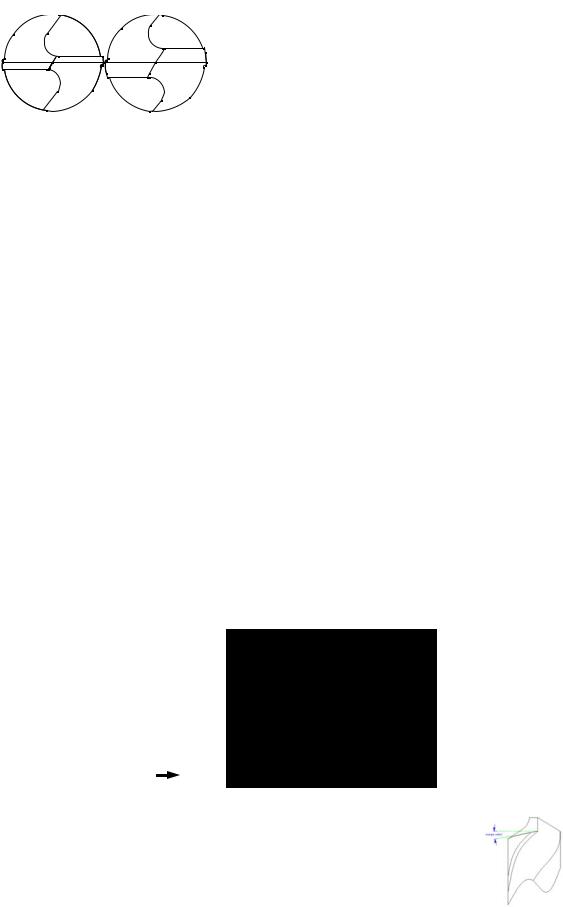
Quick Start Point Style Selections
Conic/No Split
Conic/X Split Point
Facet/No Split
Facet/X Split Point
 Quick Start Point Angle Choices
• 2 point angle options: 118° or 135°
NOTE: Factory default is “118°
Exit Quick Start Screen
•Takes you back to the Main Start-up Screen
25

This page was intentionally left blank.
26
|
|
|
Touch Screen Details |
Tools, Offset & Mainte- |
|
“SAVE” button . Any custom files or settings |
|
nance Screen Selector |
|
changed in temporary memory will be over- |
|
|
written and permanently stored. |
||
Main “TOOLS, OFFSETS & |
|
Permanent Memory File Restoration |
|
MAINTENANCE” Screen |
|
Button |
|
|
|
• |
Restore and retrieve the last 25 files and |
|
|
|
settings saved in Permanent Memory. To |
|
|
|
restore files touch the “PERMANENT |
|
|
|
MEMORY FILE RESTORATION” button . |
|
|
|
The files will be loaded into your File |
|
|
|
SAVE/OPEN screen located on the Main |
|
|
|
set-up screen. |
|
|
Setting Method of Measurement Incre- |
|
|
|
ments, Inches or Metric. |
|
|
|
|
• Use the Save Button to set the method of |
Facet Overlap Ad- |
Out of Limit Recovery |
measurement default for your XPS-16 sharp- |
|
justment See Adden- |
See Addendum |
|
ener. Whichever mode the machine is in at the |
dum for details |
for details |
|
time of saving will become the start up de- |
|
|
|
fault. |
Permanent File Save
Screen Selector
•Stores up to 25 drill files and settings at one time. Back up your custom drill files in this
screen. If files have not been saved to the permanent memory and LCD failure does occur, all custom settings and files will be lost.
WARNING: Permanent memory will hold up to 25 files at one time; to save more than 25, you must off load saved files to your PC. If you save 25 new files into permanent memory and have not saved or off loaded the previous 25 to your PC, the old files will be overwritten.
Permanent Memory Save Screen
Privacy Code Key
•Inaccessible to customer, for factory use only.
Down Load Screen
Selector
•Select this screen for in system programming and down load capabilities. As upgrades and optional custom point styles become available, your machine is equipped to receive these files from our factory to yours. To utilize each of
the following screens you will need:
1.Serial port converter with USB cable connected from PC to XPS-16
2.PC located close to XPS-16
3.Darex Sloader program must be used to transfer software upgrades and download files. For detailed instructions refer to information on page 41 & 42
Permanent Memory File Save Button
•To back up all files and settings saved
under Temporary Memory, touch the
27

Touch Screen Details
Download Screen
UI Update Button – From PC to XPS16
Upgrade your USER INTERFACE software by touching the “UI update” button.
File Down Load Button
File Down Load button - To PC From XPS-16 Send and store your custom files to your PC
File Restoration Button
File Restoration button - From PC To XPS-16 Restore saved custom files from your PC.
Controller Update Button
Controller Update button - From PC to XPS16
Update Controller software
Belt Change Screen
Selector
•When selected, the machine will move the grinding wheel assembly correctly into position for easy access to adjust or change the grind motor belt. Touch the “BELT CHANGE” button. The grinding wheel will move in to position to easily access the grind motor belt and pulley.
•The machine will go into an on hold mode and the motor will shut down.
Restart Machine screen
• Once the “Restart” icon has come up on the screen, it is safe to replace the belt.
• You will have to power off the machine and restart to continue. For more in-
structions on changing the grind motor belt.
Refer to Section 24
Wheel Position Offset Screen Selector
•Adjust wheel offsets in this screen. Make slight wheel offset adjustment after changing to a new or different
wheel. For more information see MTO Calibration Refer to information on page 59
Wheel Position Offset Screen
•After changing wheels, it may be necessary to offset the edge and/or the face of the wheel. See Sharpening Tips on page 61
•After a wheel change, call up the Darex Factory default file,
sharpen a drill and adjust wheel according to results produced in this program.
•Verify the amount of material removal from the end of a drill, if it is incorrect; offset the wheel “FACE” accordingly,
touch the +Z button , to increase the  amount of material removed from the tip
of the drill or the -Z button , to decrease the amount.
•Check the centering of the split point, if off center, offset the wheel “EDGE” us-
ing the +X button , to move the center split line towards the chisel line on the drill point, sometimes referred to as under split or the -X button to move it away, some times called over split.
28

•After offsets are entered, touch the “SAVE” button to store the “New” information and transfer you back to the previous screen. Changes to the wheel offset will return to previous setting unless the “PERMANENT FILE SAVE” is used. See Page 27.
•Selecting “CANCEL” will delete any unsaved data, retrieving the most recently saved information, transferring you back to the previous screen.
Split Point Offset Screen
Selector
•In this screen you can offset 5 different areas of the split point. A. Depth of split, B. Center of split, C. Fan Angle D. Split Angle and E.
Radius Split.
Split Point Offset Screen
|
|
E |
|
|
|
|
|
|
|
|
|
A |
|
|
C |
|
|
|
|
B |
Fan Angle |
||
|
D |
||
|
|||
|
Split Angle |
||
Α.Depth of split: Increase depth of split using the +Z button , or decrease depth of split using the -Z button
Past Center To Center Not To Center
Β.Center of split: Use the +X button , to move the center split line towards the chisel line (removes more material) on the drill point, or the -X button , to move it away. (removes less material)
Past Center To Center Not To Center
Touch Screen Details
Α.Fan Angle: This option is more for drill aesthetics than functionality. Utilizing this option may be necessary to remove more or less of
the heel to mimic a certain style. The selected split angle, amount of relief and degree of the point angle will determine the actual fan angle produced. Regard the degree entered as a reference number only, the fan angle pro-
duced has a tolerance of +/- 15°.
•Touch the “FAN ANGLE” button, the Number Key Pad will come up.
•Type in the desired fan angle degree.
•Touch the “SAVE” button to store the “New” information and transfer you back to the previous screen.
•Selecting “CANCEL” will delete any
unsaved data, retrieving the most recently saved information, transferring you back to the previous screen.
D.Split Angle: Type in the desired split angle, typically 120° to 130°. By increasing the rotation of the split angle, the split portion of the drill meets the cutting lip at a greater angle, which will give that area more strength and durability. This added split angle creates a pointed profile at the very center of the drill, which will produce a self-centering effect and reduces drill point walking at the start of a hole.
29

Touch Screen Details
Touch the Split Angle button, the Number Key Pad will come up.
•Type in the desired split angle degree, a tolerance of +/-5° can be expected.
•Touch the “SAVE” button to store the “New” information and transfer you back to the previous screen.
•Selecting “CANCEL” will delete any unsaved data, retrieving the most recently saved information, transferring you
back to the previous screen.
*Do not use the “Split Point Offset Screen” to compensate for changes in the split point due to wheel wear or a wheel change. Make all adjustments for centering split or material removal amount in “Grinding Wheel Adjustment Screen”. Refer to page 28
E.Radius Split Offset: The R-Split button will appear and will be functional only
when a web thickness value is manually input into the “Web Thickness” Screen. The “Web Thickness” Screen is located on the “Main Set up” page. The XPS-16 calculates 30% of the entered web thickness and uses that as the offset default. If this does not produce the amount of radius desired, follow the steps below. For detailed information Refer to page 35
•Touch the “R-Split” button on the Split Point Offset Screen; the Radius Offset Adjustment Screen will come up.
Radius Offset Adjustment Screen
•Touch the “OFFSET” button, the offset keypad will come up.
Radius Offset Key Pad
•Adjust the radius offset by entering an offset larger or smaller than the factory default.
•Type in the offset amount. An offset amount of .001 will produce the largest possible radius on that drill. As your offset gets larger, the radius will become smaller.
•Touch the “SAVE” button to store the “New” information and transfer you back to the previous screen.
•Selecting “CANCEL” will delete any unsaved data, retrieving the most recently saved information, transferring you back to the previous screen.
Adjusting The Rotation of the ARC/C axis
•Adjust the stopping point of the C axis or ARC/ Rotation of the radius. The factory default is 5°. This will stop the cutting edge of the drill 5° from the grinding wheel. In most cases ad-
30
 Loading...