

Page 1

®
Operating
Instructions
CAUTION: To reduce the risk of injury, the user must read and understand this
instruction manual before using this product. Save these instructions for future reference.
1
Page 2

Page 3

Table of Contents
The Darex Story .................................................................................... page 2
Safety Instructions ............................................................................... page 3
XT-3000 Specification Sheet................................................................. page 5
Capabilities & Performance .................................................................. page 6
XT-3000 Reference Drawing................................................................. page 7
Setting Up the XT3000.......................................................................... page 8
Drill Alignment...................................................................................... page
Drill Sharpening .................................................................................... page 12
Drill Point Splitting ............................................................................... page 14
Chuck Information................................................................................ page 16
Wheel Information................................................................................ page 18
General Maintenance ............................................................................ page 21
Trouble Shooting Section...................................................................... page 24
Drill Nomenclature................................................................................ page 25
Wiring Diagram.........................................
Electrical Diagram................................................................................. page 27
Chuck Parts List .................................................................................... page 28
Exploded View - Chuck ......................................................................... page 29
Parts List - Machine Rev B Serial Number ............................................ page 30
Exploded View - Machine Rev B Serial Number .................................... page 31
Exploded View - Sharpening Fixture 118°-150° (All Models)............... page 32
Exploded View - Alignment Schematic Rev B Serial Number................ page 33
Parts List - Machine Rev A Serial Number ............................................ page 34
Exploded View - Machine Rev A Serial Nu
Exploded View - Alignment Schematic Rev A Serial Number................ page 36
LEX050 - Large Drill Attachment .......................................................... page 39
LEX100 - XY Table Attachment ............................................................. page 43
LEX150 - Countersink Attachment........................................................ page 44
LEX200 - Brad Point Attachment .......................................................... page 48
LEX250 - Step Drill Attachment ............................................................ page 50
L
EX300 - 90º - 120º Drill Attachment........
LEX350 & 351 - Mini Attachment........................................................... page 58
XT3000 Auto Sharpener Attachment..................................................... page 61
*For Technical Service visit our web site at www.darex.com
Or call Darex 800-547-0222
Or contact your Darex Distributor
............................................ page 26
mber .................................... page 35
........................................... page 54
9
3
Page 4

The Darex Story
Darex Corporation began in 1973 in Beecher, Illinois. The D, A and R of Darex are the initials of three
generations of the Bernard family; David, Arthur and Richard Bernard. David and his father Richard
founded Darex. Grandfather Arthur Bernard, who earlier founded the Bernard Welding Company,
contributed his energy and guidance to Darex. Art’s inventions revolutionized the welding industry.
In 1978, Darex relocated to Ashland, Oregon. Grandson Dave and son Dick carry on Arthur’s legacy of
inventiveness. Darex grew to become the most recognized name in the cutting tool sharpening
industry. Today, Darex is a world-leading manufacturer of precision cutting tool sharpeners.
Darex is proud to offer a complete line of quality precision cutting tool sharpeners at affordable prices.
Before our first days, we at Darex had looked at our competitor’s sharpeners and asked ourselves:
“Must c
accuracy or low price inaccuracy?” Our sharpeners prove you can have it all: Simplicity, Accuracy,
and Affordability.
We have always emphasized innovative product design and tested technology. The experienced
personnel at our modern manufacturing facility use the latest production methods. The Darex
marketing team knows first-hand the machines we sell and will guide you to the best machine for
your needs. Our skilled technical service department is happy to answer your questions about our
products or cutting tools.
utting tool sharpeners be complica
ted? Why must the choice be limited to cost prohibitive
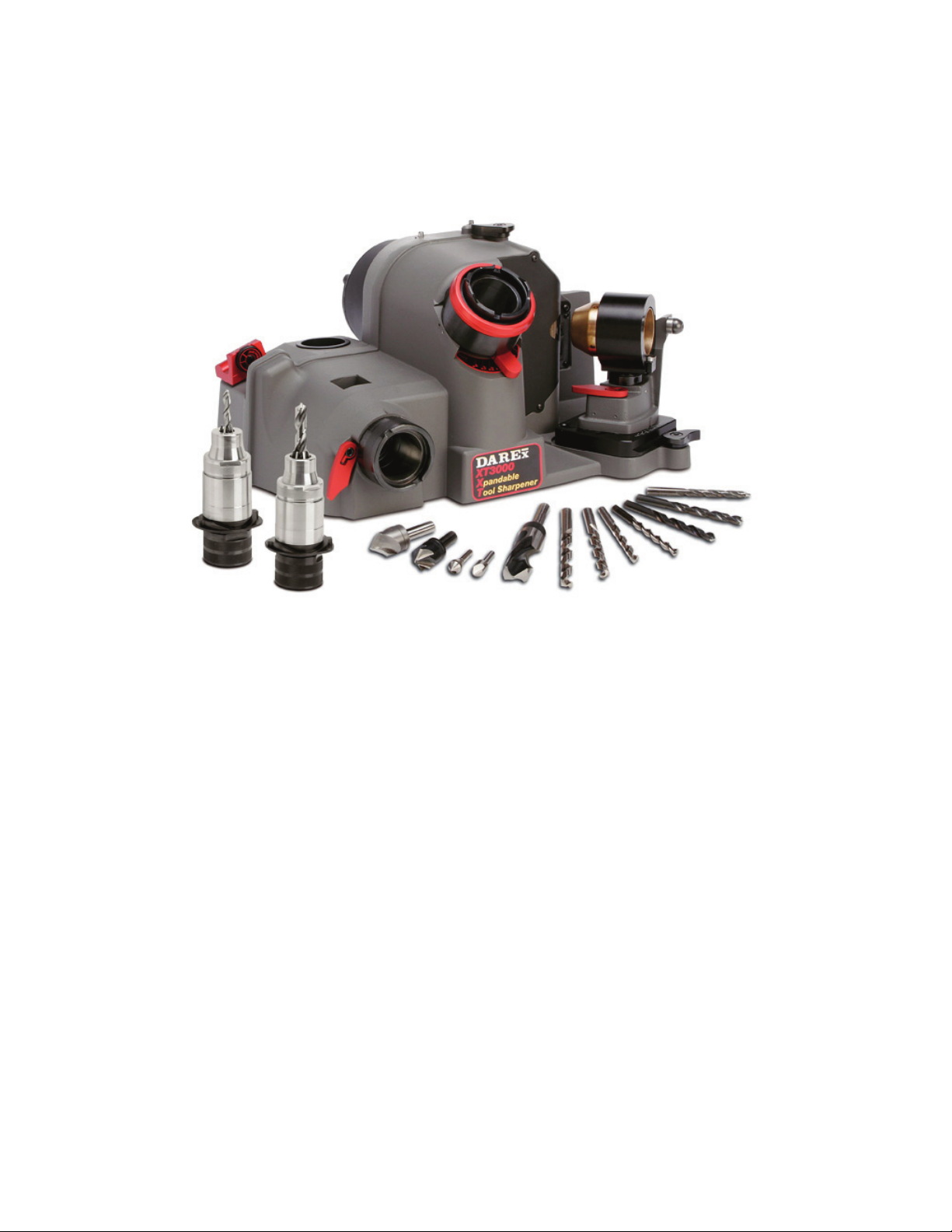
The XT-3000 Sharpener
The Darex XT-3000 Xpandable Drill Sharpener sharpens standard and split point drills at any angle
from 118 to 150 degrees. It sharpens drills sized from 3mm to 21mm. (.118 - .826) This sharpener
comes standard with CBN wheels for sharpening HSS and cobalt drills. Diamond wheels for
sharpening carbide drills are available as an option. The XT-3000 allows you to control each drill’s
point configuration including the relief and design of the split point. All adjustment and attachment
changes are done without tools. To keep your Darex XT-3000 in top condition, please refer to the
maintenance section of this manual.
Replacement wheels and parts are listed in the parts list on page 30. Schematic breakdowns begin
on page 31 of the manual.
*Optional accessories allow you to sharpen other cutting tools; including 90° spot drills, step drills,
brad points, larger drills, Weldon, single flute, 3 flute, 6 flute countersinks and left hand drills.
2
Page 5
Safety Instructions
Safety Instructions
FOR YOUR OWN SAFETY, READ INSTRUCTION
Caution:
Caution:
WHEN USING ELECTRIC TOOLS, BASIC SAFETY
PRECAUTIONS SHOULD ALWAYS BE FOLLOWED
TO PREVENT THE RISK OF FIRE, ELECTRIC
SHOCK AND PERSONAL INJURY, INCLUDING
THE FOLLOWING:
230v~,50Hz,6A
230v~,50Hz,8A
MANUAL BEFORE OPERATING MACHINE!
• WE DO NOT RECOMMEND OPERATING
MACHINE WITHOUT A VACUUM SYSTEM
RUNNING
• GRINDING DUST INHALED/INGESTED
CAN BE HARMFUL TO YOUR HEALTH.
• GRINDING PARTIALS WILL CAUSE
DAMAGE TO THE INTERNAL
COMPONENTS
• WHEN MAINTENANCE OR MACHINE
ADJUSTMENTS ARE PERFORMED ON
SHARPENER ALWAYS: Push the emergency
stop button, unplug unit from power supply
and use a “LOCK OUT” “TAG OUT” procedure.
• FOLLOW INSTRUCTIONS ENTITLED
“DAREX XT-3000 Maintenance" in this
Instruction Manual.
• NEVER TOUCH INTERNAL PARTS OF THE
S
HARPENER WHEN THE SHARPENER IS
ON The rotating grinding wheel can cause
injury.
• USE CAUTION WHEN REPLACING THE
GRINDING WHEEL Foll
entitled “How to change a wheel”, on page 18
of this Instruction Manual.
• KEEP GUARDS IN PLACE and in working
order. See Decal at left.
• REMOVE WRENCHES Always check to see
that any tools have been removed from
sharpener before turning it on.
• KEEP WORK AREA CLEAN Cluttered areas
and benches invite accidents.
• DON'T USE IN DANGEROUS
ENVIRONMENT Do not use power tools in
damp or wet locations, or expose them to rain.
Do not use tools in the presence of flammable
liquids or gases.
• KEEP WORK AREA WELL LIT
• STORE EQUIPMENT in a safe place when not
in use.
• DON'T FORCE TOOL It will do the job better
and safer at the rate for which it was designed.
• USE THE RIGHT TOOL Don’t force tool or
attachment to do a job it was not designed for.
• TO MINIMIZE THE RISK OF INJURY, ALWAYS
USE PROPER EYE AND REPIRATORY PROTECTION:
Everyday eyeglasses only have impact resistance lenses
and they are NOT safety glasses. (See Decal at left.)
Use appropriate respiratory face or dust mask.
• AVOID ACCIDENTAL STARTING Make sure
switch is in the “OFF" position before plugging
it in.
• USE RECOMMENDED ACCESSORIES
Consult the owner's manual for recommended
accessories. The use of improper accessories
may cause hazards. See Decal at left.
• CHECK FOR DAMAGED PARTS Before
further use of the tool, a guard or other part
that is damaged should be carefully checked to
assure that it will operate properly and perform
its intended function. Check for alignment of
moving parts, binding of moving parts,
breakage of
conditions that may affect its operation. A
guard or other part that is damaged should be
properly repaired or replaced.
parts, mounting and any other
ow instructions
• NEVER LEAVE TOOL RUNNING
UNATTENDED Turn power off.
• USE PROPER EXTENSION CORD Make sure
extension cord is in good condition. When using
an extension cord be sure to use one heavy
enough to carry the current the Drill Sharpener
will draw. An undersize cord will cause a drop in
line voltage, resulting in a loss of power and/or
overheating.
• DO NOT USE DAMAGED OR UNSHAPED
WHEELS Use grinding wheels suitable for speed
of grinder.
• THE CONTINUOUS A-WEIGHTED sound
pressure level at the operator’s ear is not over
60dB (A).
• RISK OF INJURY DUE TO ACC
STARTING. Do not use in an area where
children may be present.
• THE WEIGHTED ROOT MEAN SQUARE
ACCELERATION VALUE to which the arms are
subjected to does not exceed 2.5 m/s2.
• WARNING: This product contains a chemical
known to the State of California to cause cancer.
Some dust created by power sanding and grinding
as well as contents from the machine may contain
chemicals known to the State of California to cause
cancer, birth defects or other reproductive harm.
IDENTAL
3
Page 6

GROUNDING INSTRUCTIONS
• FOR ALL GROUNDED CORD CONNECTED
TOOLS:
• In the event of a malfunction or breakdown,
grounding provides a path of least resistance for
electric current to reduce the risk of electric
shock. This tool is equipped with an electric cord
having an equipment-grounding conductor and a
grounding plug. The plug must be plugged into a
matching outlet that is properly installed and
grounded in accordance with all local codes and
ordinances. Do not modify the plug provided if it
will not fit the outlet, have the proper outlet
installed by a qualified electrician. Improper
connection of the equipment-grounding
conductor can result in a risk of electric shock.
The conductor with insulation, having an outer
surface that is green with or without yellow
stripes, is the equipment-grounding conductor. If
repair or replacement of the electric cord or plug
is necessary, do not connect the equipmentgrounding conductor to a live terminal. Check
with a qualified electrician or serviceman if the
grounding instructions are not completely
understood, or if in doubt as to whether the tool
is properly grounded. Use only 3-wire extension
cords that have 3-prong grounding plugs and 3pole receptacles that accept the tool’s plug.
Repair or replace damaged or worn cord
immediately.
• GROUNDED, CORD-CONNECTED TOOLS
INTENDED FOR USE ON A SUPPLY CIRCUIT
HAVING A NOMINAL RATING LESS THAN
250 VOLTS: See Table 1 for minimum gauge
cords.
Table 1 Minimum Gauge Cords
Volts
120 V 25 / 7.5 50 / 15 100 / 30 150 / 45
Ampere Rating
M o re than Not more than
0 6 18 16 16 14
6 10 18 16 14 12
10 12 16 16 14 12
12 16 14 12
240 V 50 / 15 100 / 30 200 / 60 300 / 90
Total length of cord (feet / meters)
AWG
Not Recommended
4
Page 7
XT-3000 Specification Sheet
XT-3000
5
DRILL SHARPENER
XT-3000 Features
The XT-3000 was designed incorporating Versatility, Simplicity & Expandability. Optional attachments
sharpen other cutting tools including step drills, brad points, larger drills, Weldon and single flute
countersinks. This unit is an upgrade-able sharpener that grows with your needs. Simplicity will allow
multiple users successful results with minimal training.
Specifications for 115V & 230V
· Standard Grinding Wheels: 180 Grit CBN - HSS, Cobalt & 180 Grit Diamond - Carbide
· Max Wheel Diameter: 6.45 inch ( 164 mm)
· Arbor Size: 1.25 inch (31.75 mm)
· Wheel Surface Speed: 75 ft/sec (23m/sec) for 60 Hz Model 115V
95 ft/sec (29m/sec) for 50 Hz Model 230V
· Motor Specs: ¼ hp - 2850 rpm – 60 Hz Model 115V
¼ hp - 3450 rpm – 50 Hz Model 230V
· Operating Time: Continuous Duty
· Voltage: 115 VAC +/- 10% & 230 VAC +/- 5%
· Frequency: 60 Hz +/- 5% - Model 115V
50 Hz +/- 5% - Model 230V
· Sharpener Current: 2.5A Run / 40A Start Model 115V
1.6A Run / 25A Start Model 230V
· Accessory Current: 6.0A Run Max.
· Operating Temperature: 40° to 95° F ambient (4° to
. Humidity: Non-condensing
35° C)
Page 8
Capabilities & Performance
Capabilities & Performance
• Drill Types: Two fluted HSS, Cobalt or Carbide SAE & Metric twist drills
• Drill Point Styles: Standard Conic & Split Point
• Split Point Styles: Standard X split
• Point Angles: 118° - 150°
• Drill Diameter: 3 mm - 21 mm (.118 to .826)
• Lip Height Accuracy: ANSI B94.11, NAS 907 and ISO 10899 Standards
Decal Identifications
“Wear Safety Glasses” -
Accessory receptacle capacity -
115v~,50Hz,6A
115v~,50Hz,8A
“Do not operate without
wheel guard cover” -
6
Page 9
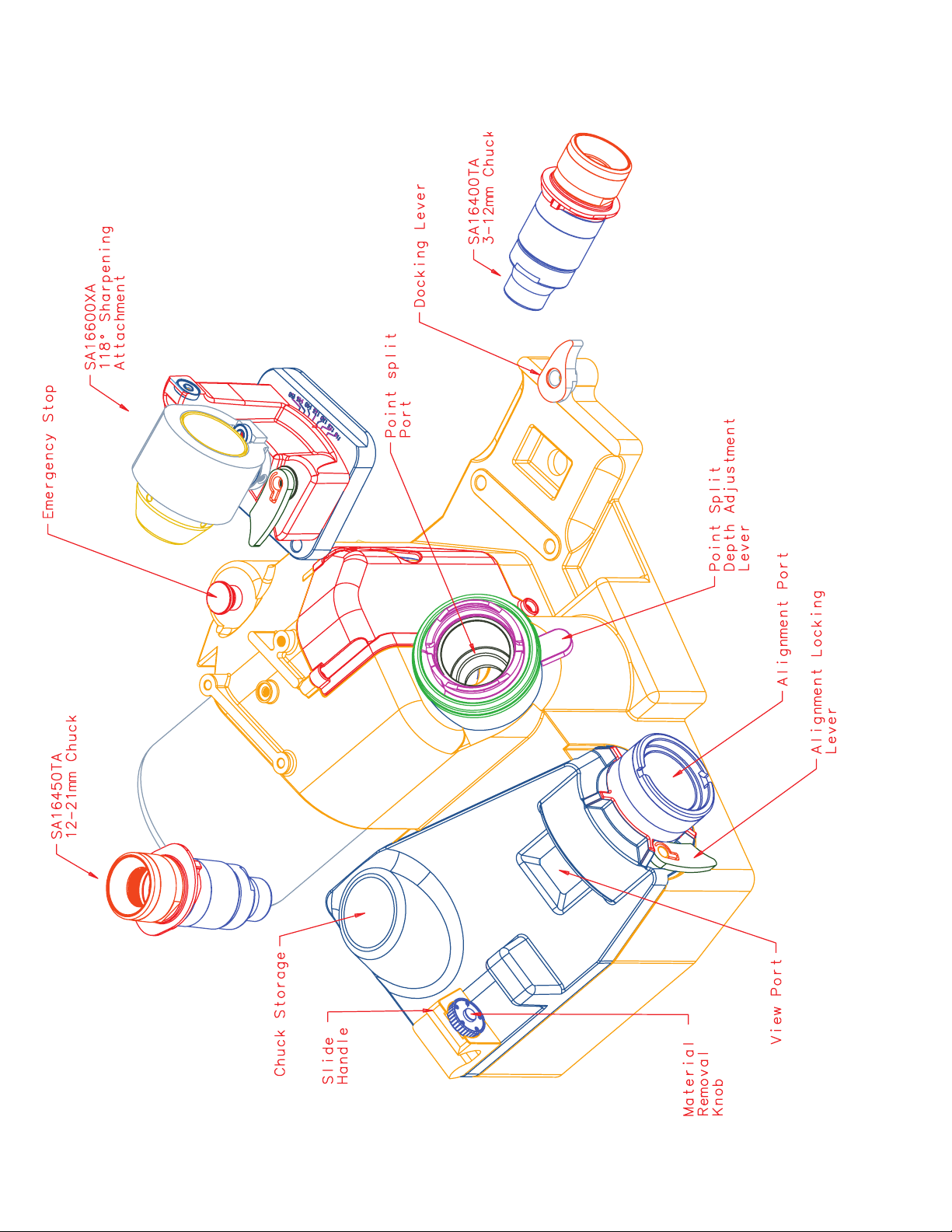
XT-3000 Reference Drawing
230V Units Only
7
Page 10
Setting up the XT3000
The XT-3000 comes equipped with grinding wheels, a
sharpening fixture and 2 chucks, 1; 3mm – 12mm & 1; 12mm
– 21mm.
1. Remove from shipping box and all packaging
material before powering up the machine. NOTE:
Due to the weight of the XT-3000, it is suggested that
the lip of the casting, located above the motor, can be
used as a handle for lifting.
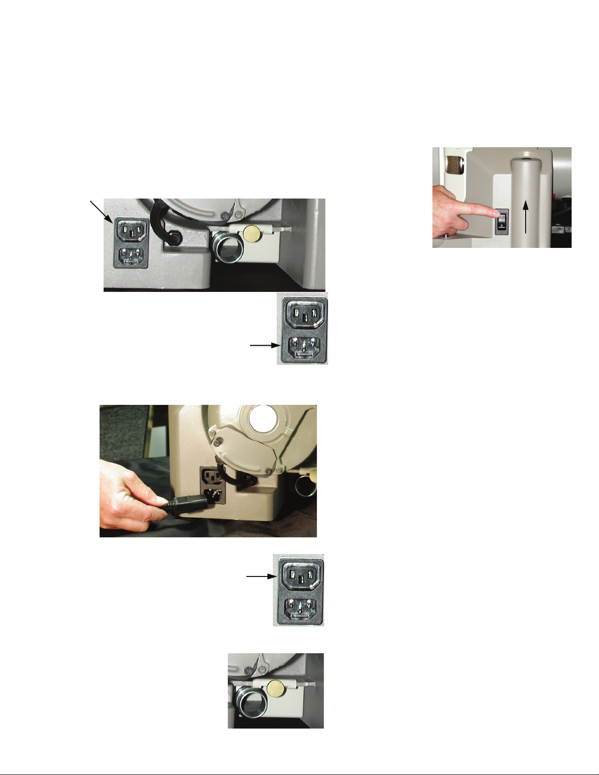
2. Located at the back and on the right side of the
XT3000 is the power receptacle. Within that
receptacle you will find a power inlet and accessory
receptacle.
3. The power inlet is located at the bottom
of the power receptacle.
the power cord in to the power inlet and then in
Plug
to the power outlet source.
6. Un-box the chucks.
7. Make sure sharpening fixture is secured
more information on mounting the sharpening
fixture. See
page 12.
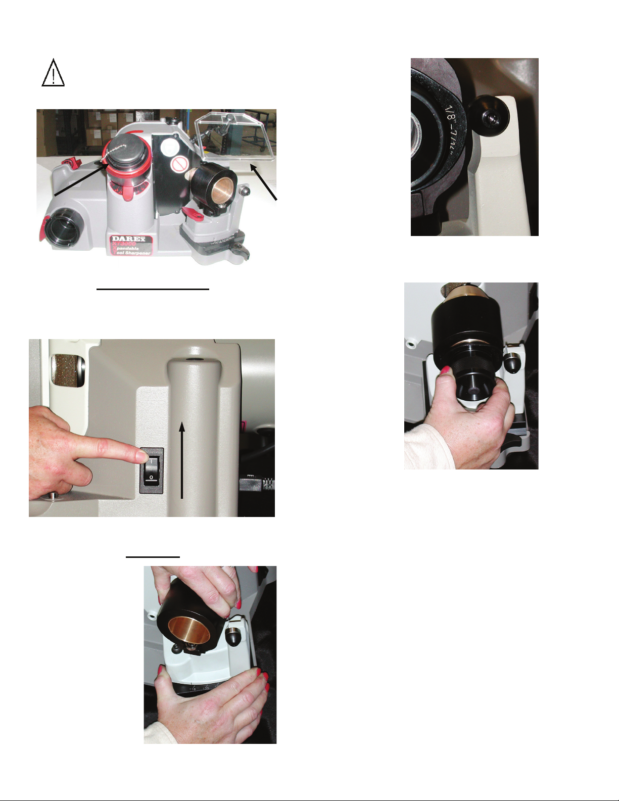
8. To power on
the machine,
push the rocker
switch to the
ON position to
start the
grinding wheel
in motion.
9. To sharpen a drill follow steps in the next three
sections; Align, Sharpen and Point Splitting.
to base. For
4. The accessory receptacle is located at the
top of the power receptacle and will allow
you to use a dust extraction system in
conjunction with the use of the XT3000.
*We highly recommend the use of a
vacuum when the machine is in use.
Darex offers a vacuum system compatible
with your XT3000. Call Darex for more information.
• SA12075EA - 115V
• SA12072EA - 230V
5. Make sure the grit tray is in
place and secure.
8
Page 11
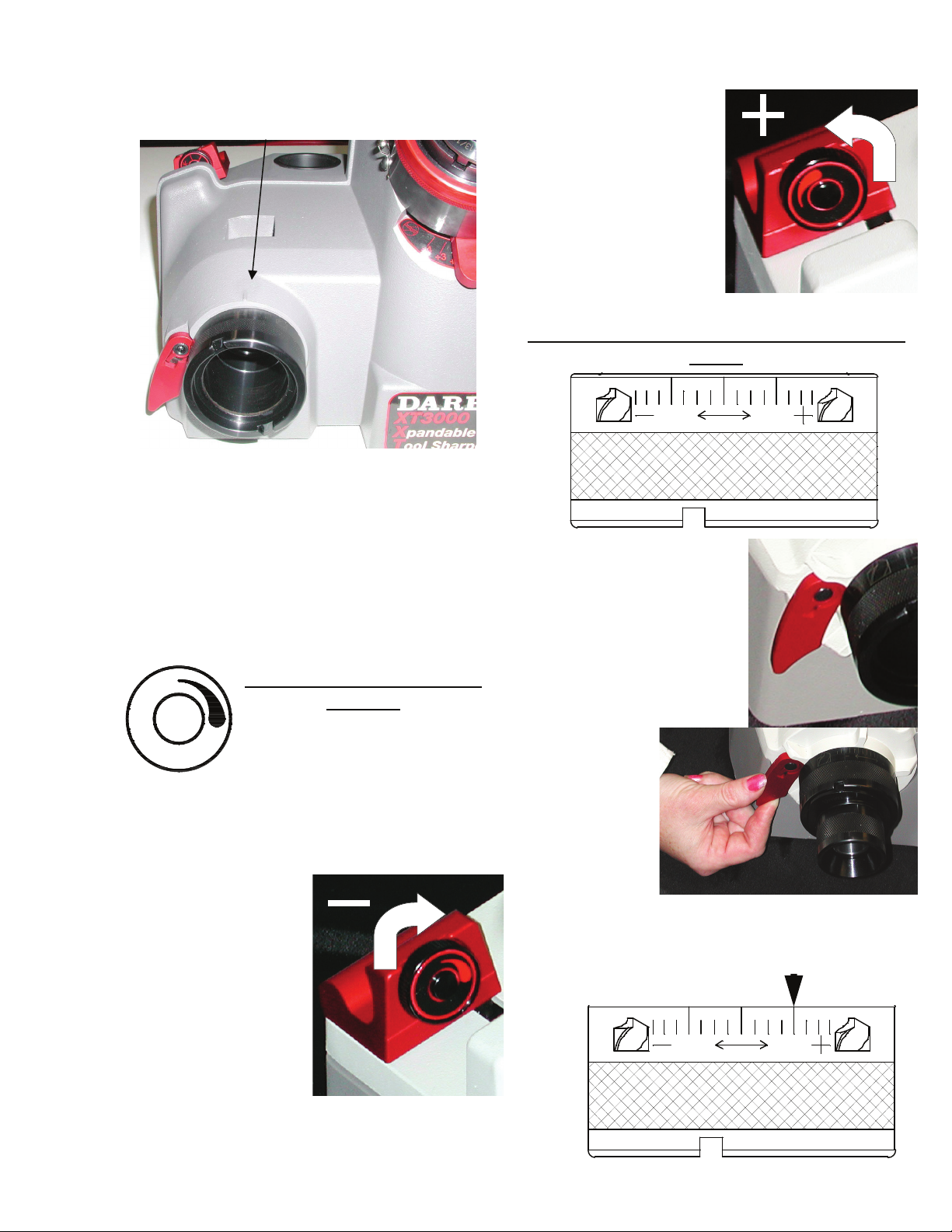
Drill Alignment
The alignment port is located on the left side of
the XT-3000.
The first stage to sharpening a drill starts with
the alignment process. In the alignment
process, you will go through a few necessary
steps prior to sharpening. Setting the material
removal amount, adjusting the alignment tube
to produce desired relief amount. Use the
Darex easy align to set the drill to length and
time the cutting edge.
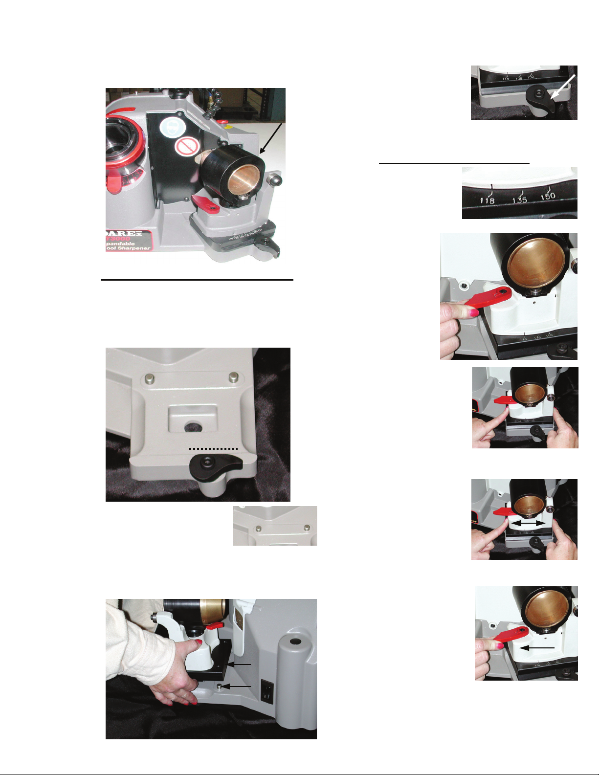
Setting Material Removal
Amount
1. Rotate the material removal
knob to adjust the amount of
stock you want to remove from
the end of the drill. Stock
removal ranges from approximately .010 .030. Remove more material if the drill is
excessively worn or damaged. Remove less
material if you are
renewing the drill.
2. Rotate the
material removal
knob clockwise to
decrease the
amount of material
removal
Tip:
Sharpen drills
on Minimum MTO to
achieve longer
wheel life.
or counterclockwise to
increase material
removal.
Setting Alignment Tube for Desired Heel
Relief
To increase or
decrease the amount of
heel relief produced
during sharpening,
change the position of
the alignment tube.
1. Lift the
alignment
locking
lever.
This will
allow you
to rotate
the alignment tube in either direction.
2. To increase heel relief, rotate the
alignment tube counterclockwise.
118°135°
118°135°
9
Page 12
Drill Alignment
To decrease heel relief, rotate clockwise.
3. To secure the alignment position,
tighten locking
lever.
118°135°
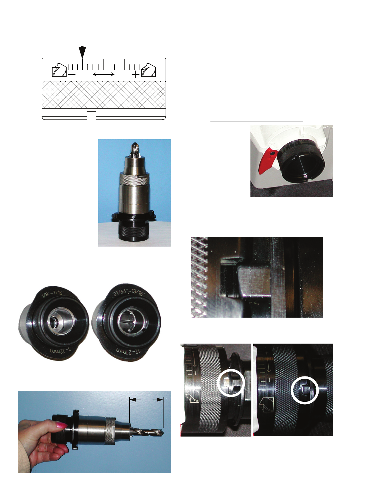
Setting the
drill to the
proper length
1. Holding the chuck
in a horizontal
position insert the drill into the appropriate
sized chuck. (Sizes are on the cam)
2. Rotate the chuck knob clockwise, which
closes the chuck jaws onto the drill. Then
slightly loosen the chuck jaws by rotating
the chuck knob counterclockwise, about ½
turn. To determine how tightly the drill
should be held during the alignment
process, the drill should slide freely and
drop out when the chuck is held in a
vertical position.
Timing the cutting edge
3. Insert the
chuck and drill
into the
alignment tube.
Align the cam dogs with the slots.
10
The cam dogs should bottom out against
the slots.
Allow the drill to protrude approximately 2
inches as shown.
2”
Page 13
Drill Alignment
4. S-L-O-W-L-Y
squeeze
together the
red slide
handle until it
touches
casting. We
emphasize
slowly,
because
squeezing the
handles too
quickly pushes
the drill too
deeply into
the chuck.
NOTE:
If this happens, the drill will not
touch the wheel during the sharpening
process.
5. With the handles held together, look
through the viewing port and see if drill is
The pawls should be seated in the helix of
the drill. If incorrect, loosen chuck knob
and repeat step 4. The jaws are most likely
gripping the drill body too tightly and will
not allow the drill to rotate into position.
CORRECT INCORRECT
6. Once the drill has been aligned correctly
and without releasing the slide handle,
tighten the chuck knob clockwise until the
chuck jaws grip the drill securely. Release
the slide handle and remove chuck from
alignment tube.
positioned correctly.
Drill point should be
touching the end of
the pusher shaft cap.
11
Page 14
Drill Sharpening
The Sharpening fixture is located on the right
side of the machine.
Mounting the Sharpening fixture
1. Rotate the locking lever so the flat edge is at
the top, horizontal and in a straight line with
the base casting.
2. Position the sharpening
fixture so that the 2
location holes on the
base of the alignment fixture are aligned
with the 3/8 dowel pins.
3. After sharpening
fixture is in place,
rotate the locking
lever clockwise until
snug. This will secure
the fixture to the base.
Adjusting the Point Angle
You must loosen the
sharpening fixture and
slide the point angle
indicator to the desired
degree.
1. To loosen, pull
the locking
lever towards
you.
2. Place fingers on each
side of the sharpening
pivot base casting.
3. Gently slide base
casting in either
direction to align
the angle
indicator with the
desired point angle
degree.
4. Secure the selected
point angle position by
pushing the locking
lever away from you
until it stops.
5. Before sharpening, make sure the sharpening
fixture is secure and no longer slides in either
direction.
12
Page 15
Drill sharpening
WARNING: Make sure Split Port Cover
and Eye Shield are in place before
sharpening. (International Models Only)
Power up machine
To turn the machine on, push the top of the
rocker switch. The machine will power up and
the grinding wheels will begin to rotate.
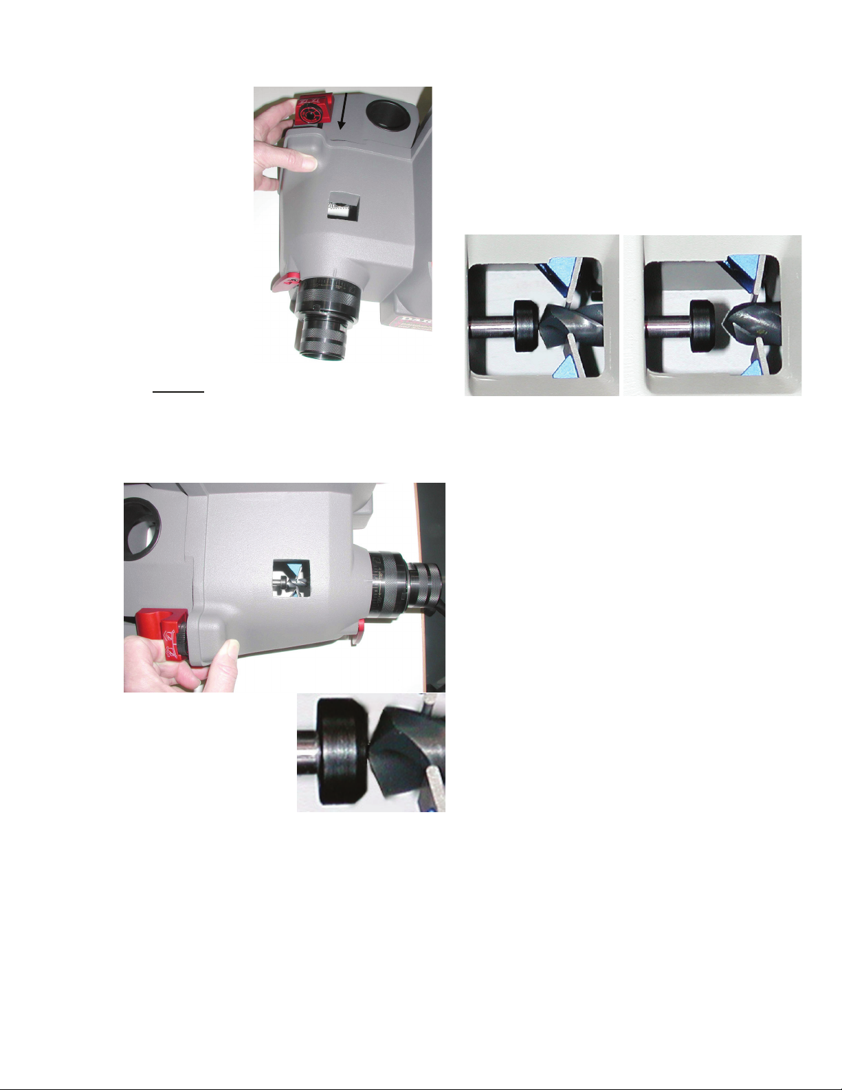
Sharpen
1. To make sure
the drill clears
the wheel, push
the sharpening
tube all the way
to the left
before inserting
chuck.
2. Insert the chuck
with the thickest
part of the cam
touching the
swing bearing.
3. Release sharpening tube very slowly.
4. With slight
pressure
towards the
grinding wheel,
rotate the
chuck 360
degrees,
several times in
a clockwise
direction. To
achieve an
efficient and
balanced
sharpening on
both cutting
edges, avoid stopping when the drill is in
the grind. Do not reposition your hand in
mid-sharpening, wait until the drill rotates
off the wheel. Continue rotating the chuck
in 360 degree rotations until the grinding
noise is minimized to a near silence.
5. Before removing the chuck, push the
sharpening tube to the left, remove
chuck. Release sharpening tube slowly.
13
Page 16
Drill Point Splitting
The Point Splitting Port is located in the center
of the machine.
Approximately 3-7° rake is created, producing a
drill with a self-centering point. Its advantages
are the ability to reduce thrust and eliminate
walking at the drill point. This is a distinct
advantage where drill bushings/fixtures are not
used.
Splitting
POINT SPLIT DIAGRAMS
DEPTH OF SPLIT DIAGRAM
Past Center To Center Below Center
Upon completion of
the sharpening
procedure, Do Not
loosen the drill in the
chuck. Insert the
chuck into the point
splitting port. Align the
cam dogs with the
slots on the point split
tube. Let the weight of the chuck ease the drill
down and onto the grinding wheel. With slight
pressure, be sure the chuck stays seated in the
point splitter.
When the grinding noise is
reduced to near silence pull the
chuck out about 1/2 way and
rotate it 180 degrees to split
the opposite side of the drill
point.
NOTE: Do not force the chuck into the grinding
wheel or damage to the drill or wheel may
occur.
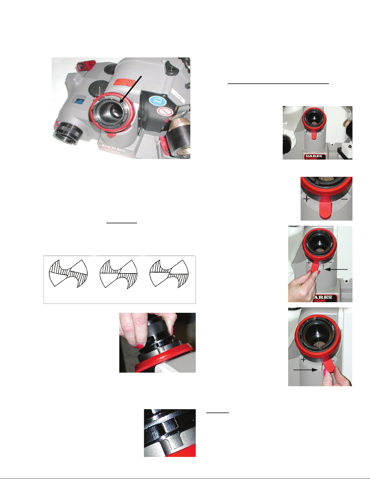
Adjusting the Depth of Split
The depth of split can vary from drill
manufacturer to drill manufacturer. The point
split depth adjustment
feature designed on the
XT-3000 makes it easy to
mimic multiple split
styles. The point split
depth adjustment lever is
attached to the point
split chuck tube. As you
move the lever, it backs the chuck tube away
from the wheel or moves it
closer into it.
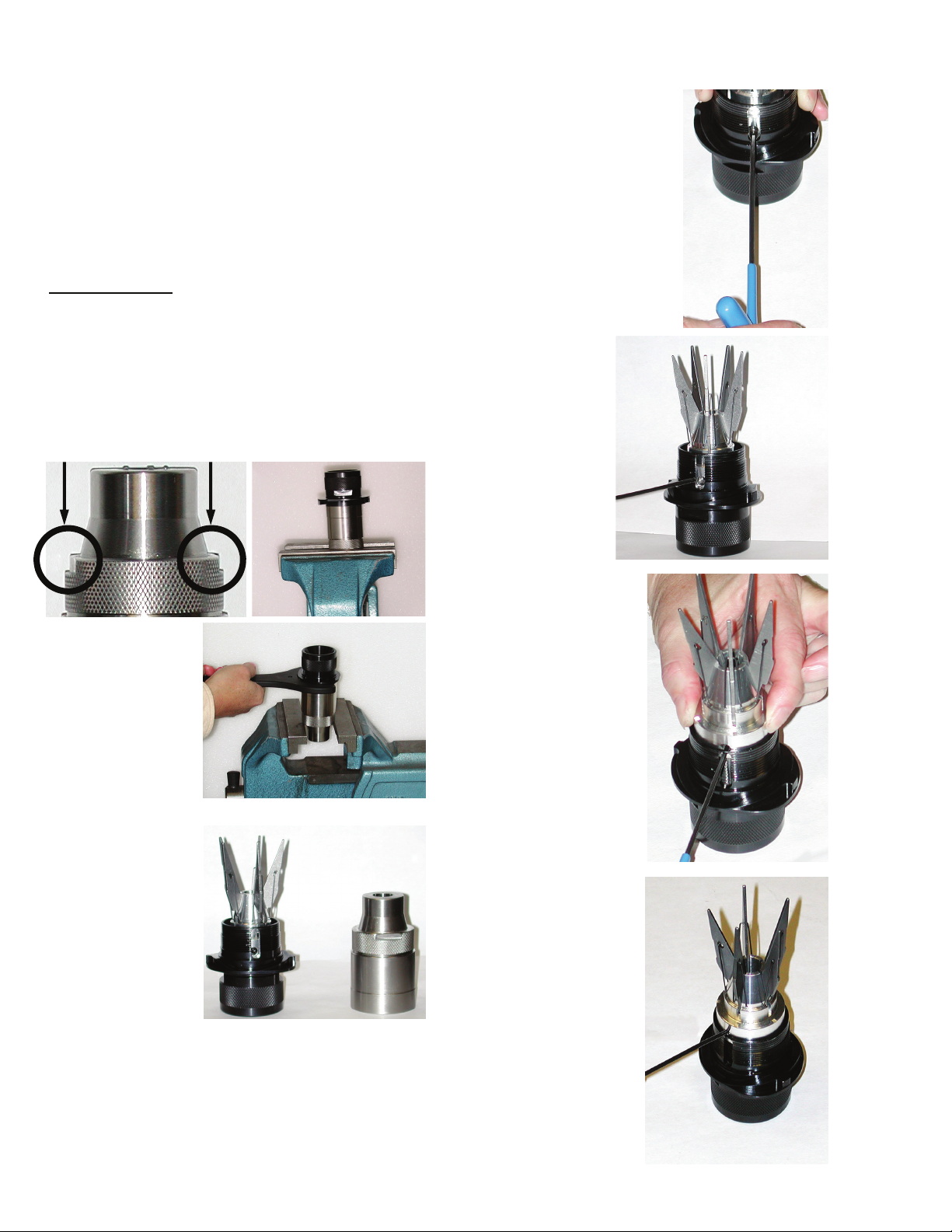
1. Located on the underside
of the point splitter is the
point split depth
adjustment lever.
2. To increase the
depth of split, push
lever to the left
toward the + sign.
This will allow the
drill to travel deeper
into the wheel,
increasing the depth
of split.
3. To decrease the
depth of split, push
the lever to the right
toward the – sign.
This will back the
drill away from the
wheel.
NOTE:
deeper than desired, you will have to regrind the
drill beyond the over split portion before splitting
again.
To correct a drill that has been split
14
Page 17
Drill Point Splitting
POINT SPLIT ANGLE
DIAGRAM
120°
130°
Pointed Flat
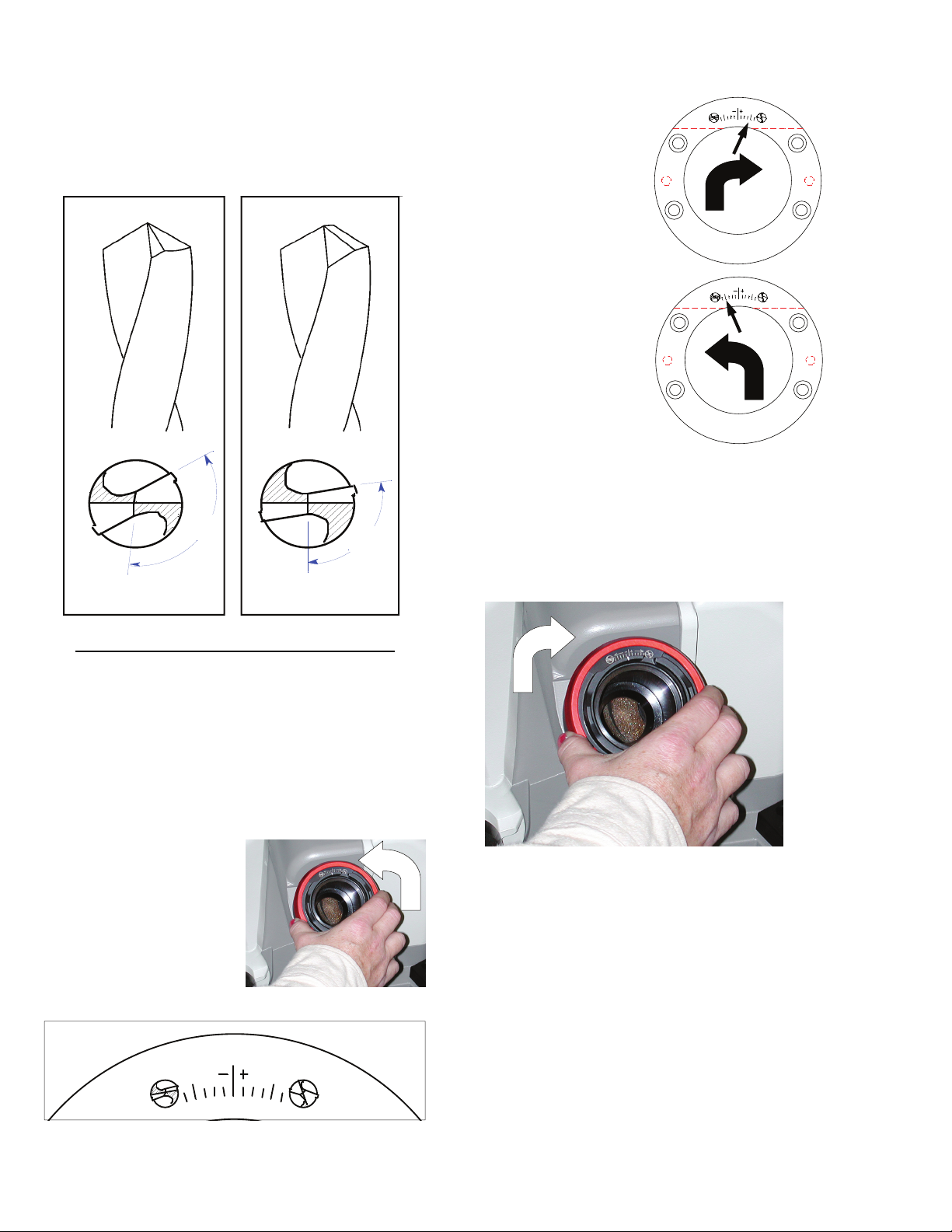
Adjusting the Split Angle Rotation
Typically the split angle of a drill is 120° - 130°
from the cutting edge. By increasing the rotation
of the split angle, the split portion of the drill
meets the cutting lip at a greater angle, which
will give the drill more strength and durability.
This added split angle creates a pointed profile
at the very center of the drill, producing a selfcentering effect and reduces drill point walking
at the start of a hole.
1. Loosen the point
split nut by
rotating the nut
counterclockwise.
2. Rotate the point
95°
105°
split angle adjuster
135°118°
clockwise to
increase the split
angle.
3. Rotate the adjuster
counter clockwise
135°118°
to decrease the
split angle.
4. Once split angle adjustment has been
made, rotate the point split nut clockwise
to retain the selected setting and secure
the point split angle adjuster.
15
135°118°
Page 18
We recommend the
Darex dust extraction system.
Chuck Information
A regular maintenance program should
be set up for each chuck. Keeping your
chuck clean and grit free will help
maintain drill concentricity and lengthen the life
of your chucks. For detailed cleaning
instruction, See Maintenance page 22.
XT-3000 CHUCKS
The XT-3000 jaw chuck system was designed
with accuracy and simplicity in mind. As a result,
the XT-3000 chuck allows you to cover a large
diameter range of drills without the aid of
individual collets. You can quickly change from
the largest drill diameter to the smallest in
seconds. The accuracy of the chuck will produce
drills that exceed ANSI, NAS 907 & & ISO 10899
standards. The various chucks and accessories
have drill diameter capabilities that range
from .059” – 1.1875” (1.5mm to 30mm).
Make sure large drills are secure
after tightening the chuck.
Morse Taper drills:
To secure a Morse Taper drill in the chuck, it is
necessary for the drill to have a minimum flute
length of 4.000 inches. The taper will then be
free from the grasp of the jaws, eliminating
interference with the larger tapered shank. The
other option for holding these types of drills is a
split bushing. Bush the body of the drill up to or
larger than the interfering diameter.
End Mill shank drills:
Typically, an end mill drill has a shank diameter
larger than the body of the drill.
Some End Mill shank drills can be sharpened on
the XT-3000, depending on the length of the
flute verses the length of the shank.
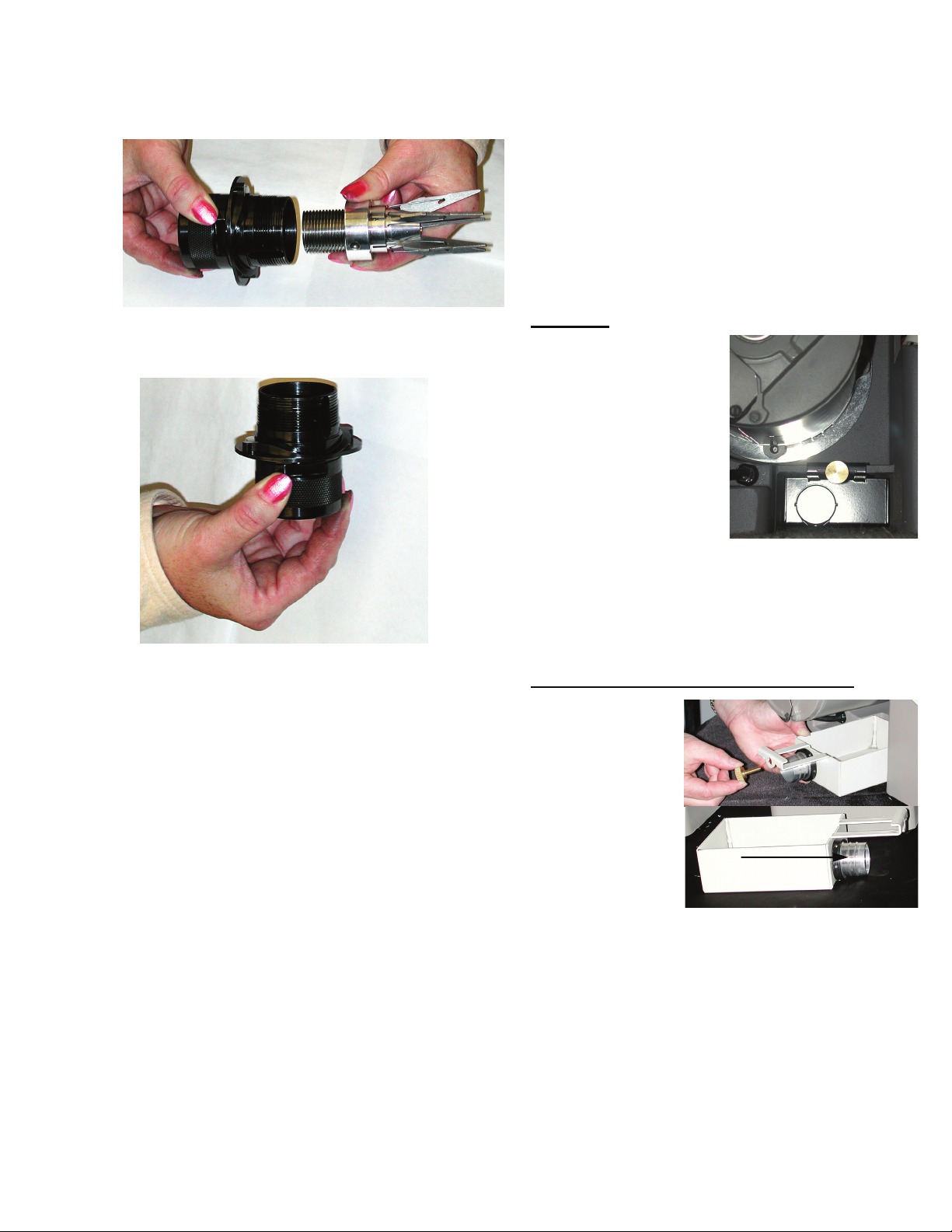
CHUCK DISASSEMBLY &
MAINTENANCE
chuck assembly should be disassembled and
cleaned periodically.
The use of a dust extraction system
during grinding will help reduce the
amount of maintenance, however, the
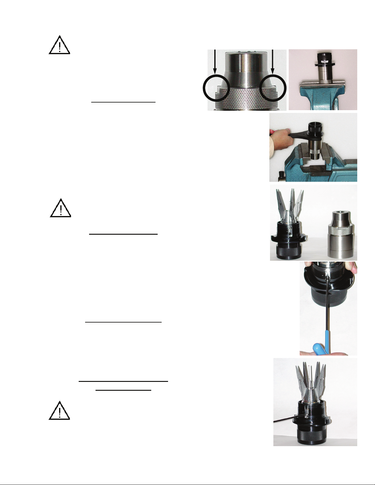
1. Place flats of chuck body into a vice, do not
over tighten.
2. Place chuck
wrench,
PP16480SF,
(optional) on
dogs of chuck
knob assembly.
Rotate wrench
counterclockwise to
remove chuck
knob/jaw
assembly from
chuck body.
3. Using a 2.5 mm hex
wrench remove set screw.
4. The internal
pieces must
remain keyed, in
order to remove
the closing screw
from the chuck
knob assembly.
Insert the 2.5
mm wrench into
the set screw
hole.
16
Page 19

Chuck Information
5. Rotate chuck knob
counter clockwise
until the wrench
reaches the top of
the slot.
6. Remove wrench and
reinsert into the set
screw hole above the
slot.
7. Rotate the chuck knob counterclockwise until
the closing screw exits the knob assembly.
8. The chuck knob assembly does not come
apart from this point.
TO REASSEMBLE:
Reassemble in reverse order.
CHUCK DESCRIPTIONS AND PART #’S
SA16400TA - 3-12 mm Standard Chuck
SA16450TA - 12-21mm Standard Chuck
SA16500TA - 21-30mm Large Drill Chuck
SA16975TA - 3-12mm Step Drill Chuck
SA16980TA - 12-21mm Step Drill Chuck
SA16890TA - 3-12mm 90° Chuck
SA16880TA - 12-21mm 90° Chuck
SA16916TA - 3-12mm Brad Point Chuck
SA16918TA - 12-21mm Brad Point Chuck
SA16484TA - 3-12mm Left Hand Chuck
SA16488TA - 12-21mm Left Hand Chuck
SA16401TA
SA17010TA - 3-12mm Auto Geared Chuck 3-12mm
SA17025TA - 12-21mm
- 1.5-7mm 1.5-7mm Chuck
Auto Geared Chuck 12-21mm
17
Page 20
XT-3000 WHEEL INFORMATION
The Darex XT-3000 comes equipped with
electroplated CBN (Cubic Boron Nitride). Optional
Diamond wheels are available. The wheel comes
installed on your sharpener ready to sharpen
drills.
Sharpening with an electroplated CBN (Cubic
Boron Nitride) or Diamond grinding wheel reduces
grinding cost and improves quality of the finished
product. These results are obtained because the
grinding material is super abrasive. The CBN is
second only to diamond in hardness. In fact, CBN
has twice the hardness and four times the
abrasion resistance of an aluminum oxide grinding
wheel. The CBN and Diamond wheel last longer;
the grinding process is faster and less grinding
time is lost due to wheel breakdown &
maintenance.
WHEEL MAINTENANCE
These wheels are maintenance free from truing
and dressing but will need to be cleaned
periodically.
the machine using a lock out tag out
procedure. After removing the wheel from the
sharpener, saturate the wheel with any type of
oil-less solvent, such as Automotive Brake
Cleaner.
and lightly brush the saturated wheel, loosening
the impacted grinding particles. Re-saturate the
wheel to flush out any loosened debris. Do not
use any type of dressing tool on these wheels.
Damage to surface will occur and greatly shorten
the wheel life.
NOTE:
discolor or burn, the wheel life may be exhausted
and the wheel will need to be replaced.
Disconnect the power from
It is helpful to use a soft bristle brush
If after cleaning wheel, the drills still
are available if carbide is to be sharpened
on this machine.
WHEN TO REPLACE THE
WHEEL?
Eventually, the long-life electroplated wheel in
your XT-3000 will wear out. Indicators that a
wheel change is necessary are: a drop in
performance such as drill burning or excessively
slow sharpening time. Inspect the wheel for
abrasive quality. A worn wheel will appear
smooth. If it is necessary, replace the worn
wheel(s). New wheels will initially produce a
coarser grind. However, this aggressiveness will
disappear after approximately the first one
hundred drill sharpenings. Under normal use,
you should experience 4-6 thousand drill
sharpenings from each new wheel.
*Darex does not re-plate or recommend replating the grinding wheels. For replacement
wheels, contact your Darex distributor or Darex .
HOW TO CHANGE A WHEEL
1. Unplug unit from power supply
and use a “LOCK OUT” “TAG OUT”
procedure.
WHEEL DESCRIPTIONS AND
PART#’S
• PP16050GF – 180-grit CBN grinding wheel
• PP16060GF – 100-grit CBN Point Split
grinding wheel
• PP16052GF – 180-grit Diamond grinding
wheel
• PP16062GF – 260-grit Diamond Point Split
grinding wheel
• PP16070TF – Grind wheel retainer
Do not attempt to grind carbide drills
with CBN wheels. Diamond wheels
2. Using a
3mm hex
key, remove
3; 3mm
socket head
cap screws
(PP12240FF)
from whee
guard cover.
l
18
Page 21
Wheel Information
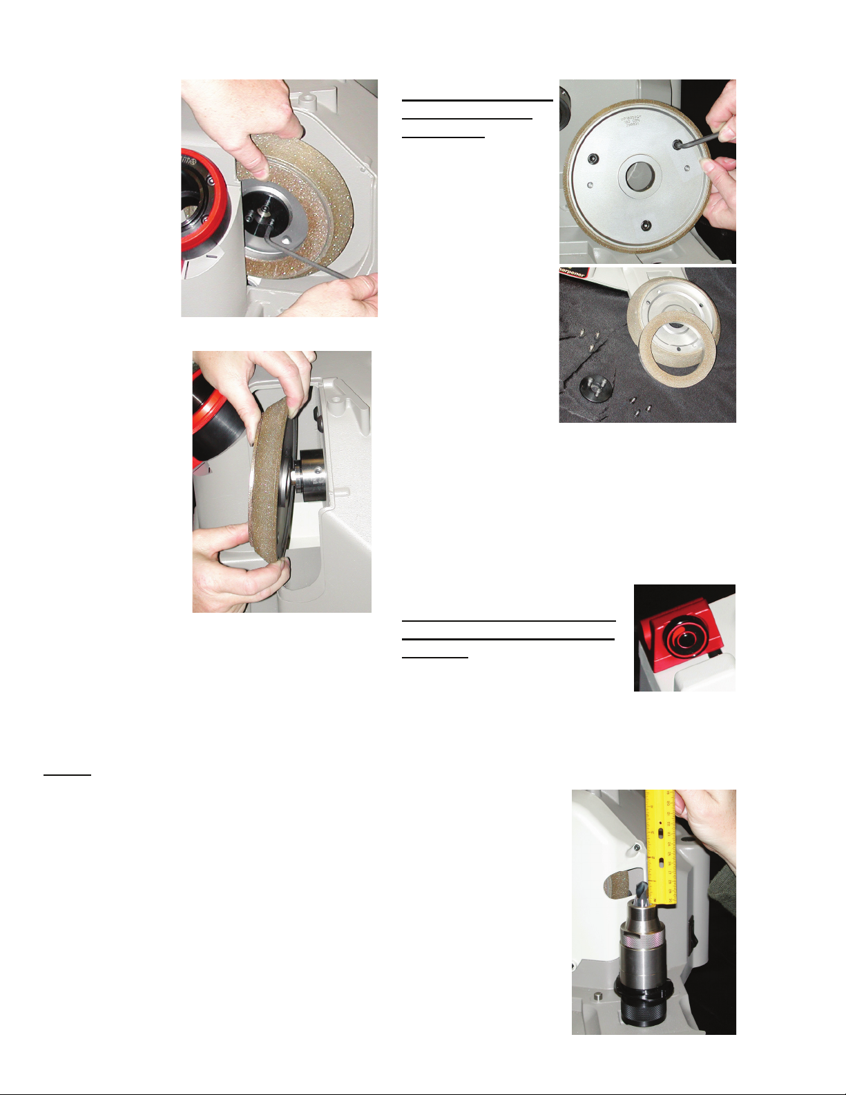
3. Pull wheel
guard cover
away from
wheel.
4. Using a 4 mm
hex key,
remove 3;
5mm socket
head cap
screws (PP16318FF) & split washer
(PP08650FF)
from grinding
wheel retainer.
5. Remove the
wheel retainer.
6. Pull wheel
toward you
then to the
right and out of
the machine
cavity.
7. Clean the machine cavity as well as the
mounting hub and wheel before
reinstalling.
8. Repeat steps in reverse to install new
wheel.
NOTE: Because the Darex grinding wheel
cannot be trued it is critical that the motor hub &
wheel register be cleaned. Once wheel has been
installed, rotate the wheel by hand to check that
the wheels run true. If not, loosen the screws ,
reposition the wheel and tighten the screws.
Separating grinding
wheel from point
split wheel
The grinding and point
split wheel are piggy
backed and bolted
together. To change
any one of the wheels
you must first
separate them. You
can access the bolts
from the back side of
the sharpening wheel.
1. Using a 5mm
hex key, remove
the 3; 6mm
socket head cap
screws
(PP16348FF) & split washers.(PP07013FF)
2. The two wheels can now be separated.
Recalibrating Material
Removal
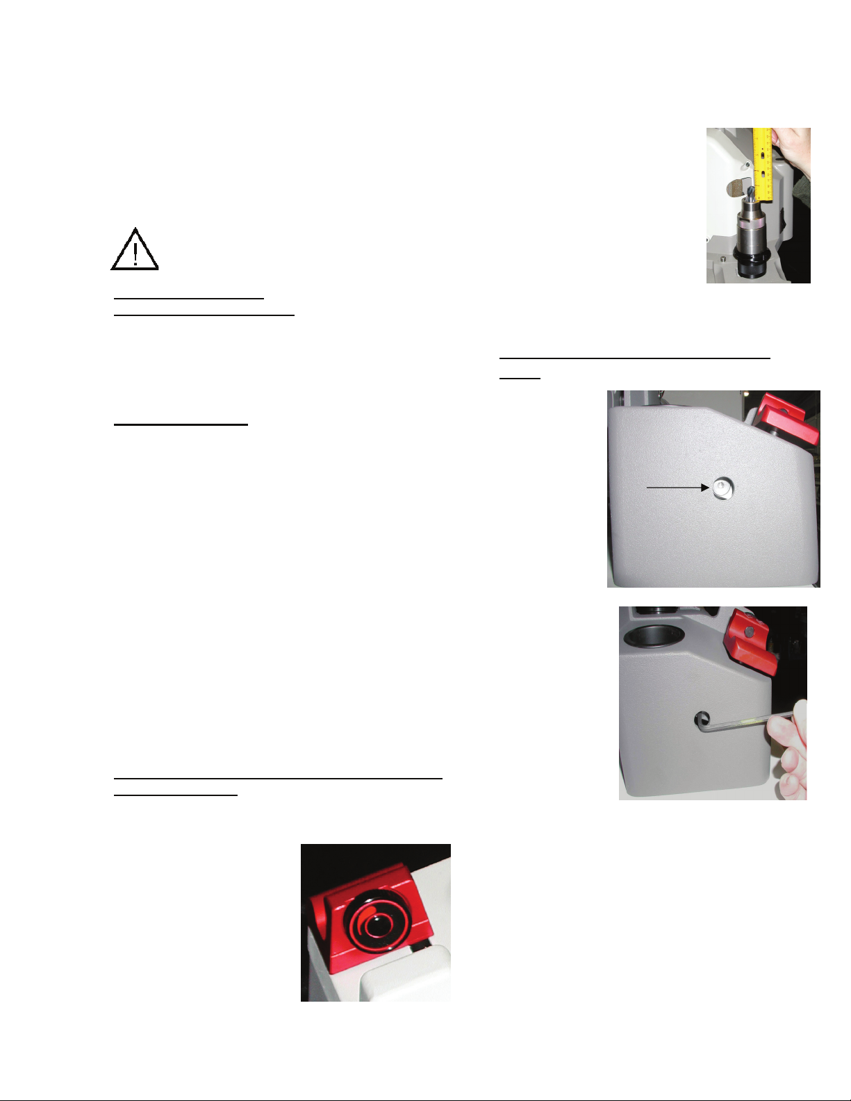
After a wheel change, verify
and/or recalibrate material
removal.
Use a 3/8 HSS standard twist
drill, measure the length of drill
before sharpening.
1. Rotate material removal knob to maximum
take off.
2. Align drill as
though you intend
to sharpen it.
Follow Alignment
steps on page 9.
3. Once drill is set to
length, aligned
and captured in
the chuck
securely, remove
from alignment
port.
19
Page 22
4. Measure the amount of drill protruding
from the end of the chuck to the tip of the
drill.
5. The length of the drill protruding from the
top of the chuck should measure .970-.980
(24.63 mm - 24.89 mm)
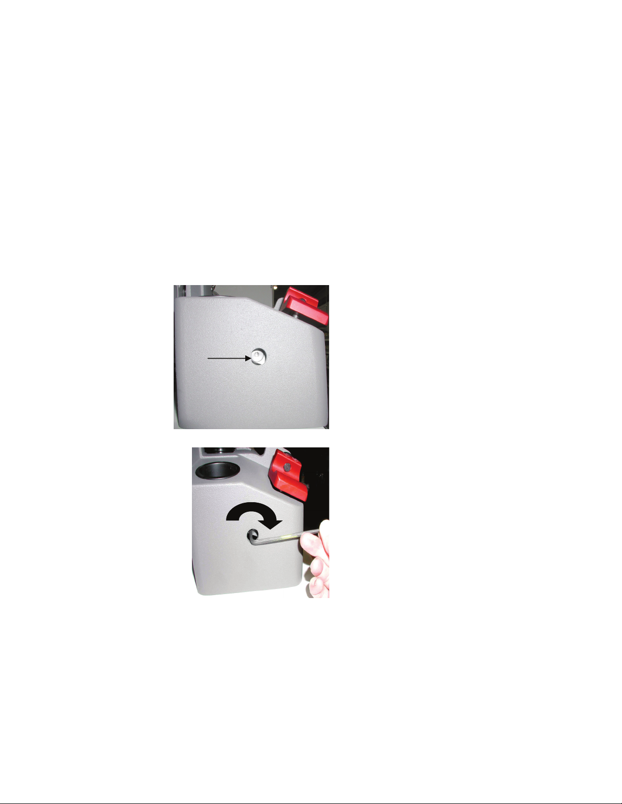
Calibrating the Material
removal knob
1. At the rear of the machine base there is a
small
access
hole.
2. Insert a
3/16 Allen
wrench into
the access
hole.
3. To advance the
pusher shaft cap,
reducing the
amount of drill
stick out, rotate
the wrench
clockwise.
4. To retract the
pusher shaft cap,
increasing the
amount of drill stick out, rotate the wrench
counterclockwise.
Each ¼ turn will adjust .010 (.25 mm) or one
full turn will adjust .04 (1.0 mm) After adjusting
the pusher shaft assembly, realign the drill and
re-measure the amount of stick out. Repeat the
steps 1-4 until the drill protrudes .970-.980 in
length. (24.63 mm - 24.89 mm)
Wheel Information
At the Minimum material removal setting, approximately .005 (.127mm) should be removed from the end of the drill.
20
Page 23
GENERAL MAINTENANCE
To extend the life of your
sharpener, we recommend a
routine maintenance program be
put in place. Every
120-machine hrs is suggested, or
more often if necessary.
WARNING: Remove the plug before
carrying out any adjustment, servicing or
maintenance.
Vacuum system:
Optional but recommended.
Using a dust extraction system can improve the
sharpening life of the machine. Unplug vacuum
from power source. Check filter or canister on a
regular basis.
Wheel cleaning:
These wheels are maintenance free from truing
and dressing but will need cleaned periodically.
After removing the wheel from the unit, saturate
the wheel with any type of oil-less solvent, such
as Automotive Brake Cleaner. It is helpful to use
a soft bristle brush and lightly brush the
saturated wheel, loosening the impacted
grinding particles. Re-saturate the wheel to flush
out any loosened debris.
Always clean a brand new wheel before
using.
If after cleaning wheel, the drills still
discolor or burn, the wheel life may be
exhausted and the wheel will need to be
replaced.
Recalibrating Material Removal
After a wheel change, verify and/or recalibrate
material removal.
Use a 3/8 HSS standard twist drill, measure the
length of drill before sharpening.
1. Rotate material
removal knob to
maximum take off.
2. Align drill as though
you intend to
sharpen it. Follow
Alignment steps on
page 9.
3. Once drill is set to
length, aligned and captured in the chuck,
securely remove from alignment port.
4. Measure the amount of drill
protruding from the end of
the chuck to the tip of the
drill, before sharpening.
5. The length of the drill
protruding from the top of
the chuck should
measure .970-.980 (24.63 mm - 24.89
mm)
Calibrating the Material removal
knob
1. Located at
the rear of
the machine
base, you
will find a
small access
hole.
2. Insert a 3/16
Allen wrench
into the access
hole.
3. To advance the pusher shaft cap, reducing
the amount of drill stick out, rotate the
wrench clockwise.
4. To retract the pusher shaft cap, increasing
the amount of drill stick out, rotate the
wrench counterclockwise.
Each ¼ turn will adjust .010 (.25 mm) or one
full turn will adjust .04 (1.0 mm). After adjusting
the pusher shaft assembly, realign the drill and
re-measure the amount of stick out. Repeat the
steps 1-4 until the drill protrudes .970-.980 in
length. (24.63 mm - 24.89 mm)
21
Page 24
General Maintenance
Chuck Maintenance
Chuck maintenance is very important. To sustain
the life of your chucks and to maintain precision
lip height concentricity, clean the chucks on a
regular basis. Some tools are necessary to
disassemble the chuck, You will need: Wrench
PP16480SF (Optional)
Disassembly:
The use of a dust extraction system while
grinding will help reduce the amount of
maintenance necessary, however, periodically
the chuck assembly should be disassembled and
cleaned.
1. Place flats of chuck body into a vice.
2. Place chuck
wrench on dogs of
chuck knob
assembly.
3. Rotate wrench
counterclockwise to
remove chuck
knob/jaw assembly
from chuck body.
4. Using a 2.5 mm hex
wrench, remove set screw.
5. The internal
pieces must remain
keyed in order to
remove the closing
screw from the
chuck knob
assembly. Insert the
2.5 mm wrench, into
the set screw hole.
6. Rotate chuck knob
counterclockwise until
the wrench reaches the
top of the slot.
7. Remove wrench and
reinsert into the set
screw hole above the
slot.
22
Page 25
General Maintenance
8. Rotate the chuck knob counterclockwise until
the closing screw exits the knob assembly.
9. The chuck knob assembly does not come apart
from this point.
Chuck Cleaning:
Once disassembled, clean all parts with a type of
oil-less solvent such as Automotive Break Cleaner.
Chuck Re-assembly:
Reassemble in reverse order.
Point Split Tube Cavity:
Routinely vacuum and using a dry cloth, wipe out
the inside of the Point Split Tube. Removing
grinding dust will help produce consistent split
point drills by retaining the ID dimensions of the
tube and reducing early wear.
Sharpening Tube Cavity:
Using a dry cloth, wipe out the inside of the brass
tube, removing grinding dust. Over time it may be
necessary to replace the sharpening tube. The
sharpening tube is threaded into the housing
using right-handed threads. To remove, rotate
tube counterclockwise using a spanner wrench.
Replace as needed.
Wheel Housing Cavity:
While grinding wheel is out of machine and before
replacing wheel, vacuum out wheel housing and
wipe around the hub area.
External Machine Castings:
Wipe down external machine castings with a
mild household cleaner.
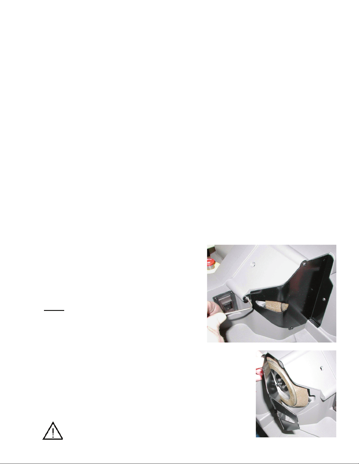
Grit Tray/Vacuum Port Connection:
Grit tray
At the back of the
machine, located
underneath the
grinding motor is the
grit tray. Drill grindings
will accumulate inside
the grit tray. The grit
tray has a magnetic
liner to attract and hold
these dust particles. Do
not let the tray become more than 1/3 full. To
remove tray, unscrew brass thumb screw.
Remove tray and dump contents. Wipe excess
dust from the tray with a rag.
Vacuum Port Connector (Optional)
The grit tray has
a knock out plug
that can be
removed by hand
and replaced with
the vacuum tube
(SA16030TA).
Use this port to
connect a vacuum
hose to the
XT3000. This method of extracting dust
particles from the machine will keep it cleaner
and is recommended.
Oil Lubrication:
Never use an oil-based lubricant on any part
of this machine! Oil-based lubricant will collect
grinding dust particles. Powdered graphite
may be applied to any sliding parts located on
the machine.
23
Page 26

Trouble Shooting XT-3000 Drill Sharpening
Symptom
Using ON/OFF switch does not work
Machine won’t power up
Cause
• No power at outlet
• Make sure power cord is plugged in to
machine and outlet
• Release e-stop (230v machine only)
• E-stop nut is loose and stuck down in the
off position (230v machine only)
• On/off switch needs to be replaced
• Wiring lead disconnected
• Grinding wheel obstructed and can’t rotate
• Grinding motor bad
Symptom
Tip of drills burn or discolor
Cause
• Wheel needs to be cleaned
• Material take off too aggressive
• Wheel needs to be replaced
Symptom
Unable to secure drill in or release drill
from chuck
Cause
• Tapered shank drill
• The drill may have a slight taper to the
body
• Shank of drill larger than body
• Drill has multiple diameters that are
interferi
• Incorrect drill diameter for that particular
ch
• Drill flutes are damaged or have burrs
• Chuck needs to be cleaned
Symptom
Drill incorrectly split
Cause
• Check settings on the split point fixture
• Did not align correctly
• Point Split Tube calibration is off
Symptom
Material take off varies
Cause
• Wheel not secure to motor hub
• Wheel calibration is off after new wheel
change
• Cam dog not properly seated in alignment
slot during alignment set up
• Drill is pushing back in the chuck during
grinding
• Operator is not sparking drill out
ng with jaws
uck
Symptom
No material take off during grinding
Cause
• Drill loose in chuck
• Drill tip not touching the pusher shaft cap
during alignment process
Symptom
Length of time drill is in the grind becomes
excessive
Cause
• Material take off too excessive
• Grinding wheel needs to be cleaned
• Grinding wheel needs to be replaced
Symptom
Lip h
eight concentricity is out of tolerance
Cause
• Material take off too excessive
• Chuck needs to be cleaned
• Sharpening tube needs to be cleaned
• Chuck is worn out and needs to be
replaced
• Sharpening tube is worn and needs to be
replaced
• Wheel is not running true
24
Page 27
DRILL NOMENCLATURE
Drill Nomenclature
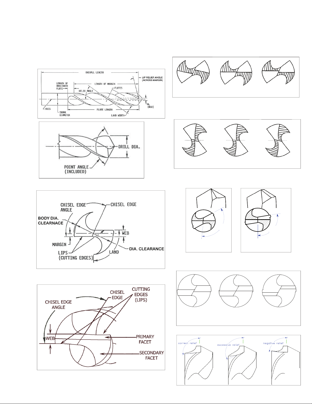
FACET & CONIC DRILL STYLE
PICTURE AND
NOMENCLATURE
CONIC DRILL
CLEARANCE
FACET DRILL
POINT SPLIT
DEPTH OF SPLIT DIAGRAM
Past Center To Center Below Center
CENTER OF SPLIT DIAGRAM
Past Center To Center Below Center
POINT SPLIT ANGLE DIAGRAM
120°
130°
Pointed Flat
Facet Diagram (
re-sharpen on the XPS16)
95°
105°
Past Center
(over facet) (under facet)
To Center Below Center
RELIEF
25
Page 28

Wiring Diagram
26
Page 29

Electrical Diagram
27
Page 30

Chuck Parts List
ITEM ITEM_DESC ITEM ITEM_DESC
SA16425SA JAW SET (5 PIECES) SA16425SA JAW SET (5 PIECES)
1-3 FL53461PP ECAR WAJ MM21-3 FL53461PP
ITEM ITEM_DESC ITEM ITEM_DESC
SA16427SA JAW SET (7 PIECES) SA16427SA JAW SET (7 PIECES)
J MM12-21 FL07461PP ECAR WAJ MM12-21 FL07461PP
1PP
ITEM ITEM_DESC ITEM ITEM_DESC
M03-12 FT53561PP
28
)DRADNATS( KCUHC LLIRD PETS MM21-3 AT57961AS KCUHC MM21-3 AT00461AS
)N S PB B( YDOB KCUHC MM21-3 FT00461PP )N S PB B( YDOB KCUHC MM21-3 FT00461PP
)SECEIP 5( SGNIRPS WAJ KCUHC AR56521AS )SECEIP 5( SGNIRPS WAJ KCUHC AR56521AS
SSS MM01 X MM8. X MM5 FF04461PP SSS MM01 X MM8. X MM5 FF04461PP
)N S PB B( EDIUG WAJ MM21-3 FT03461PP )N S PB B( EDIUG WAJ MM21-3 FT03461PP
ECAR WAJ MM2
)N S PB B( WERCS GNISOLC MM21-3 FT02461PP )N S PB B( WERCS GNISOLC MM21-3 FT02461PP
)N S PB B( EVEELS GNISOLC MM12-3 FT51461PP )N S PB B( EVEELS GNISOLC MM12-3 FT51461PP
GNIR PANS MM12-3 FF24461PP GNIR PANS MM12-3 FF24461PP
REHSAW TSURHT 1 & 8/5 4/1 FS40420PP REHSAW TSURHT 1 & 8/5 4/1 FS40420PP
MAC LLIRD PETS MM21-3 FT57961PP )B( MAC MM21-3 FT50461PP
B B( BONK KCUHC MM12-3 FT01461PP )N S PB B( BONK KCUHC MM12-3 FT01461PP
SSS MM01 X MM8. X MM5 FF04461PP SSS MM01 X MM8. X MM5 FF04461PP
ECAR WA
GNIR PANS MM12-3 FF24461PP GNIR PANS MM12-3 FF24461PP
)SECEIP 5( TES WAJ AS52461AS )SECEIP 9 ( SWAJ KCUHC MM03-12 AS03561AS
SSS MM01 X MM8. X MM5 FF04461PP SSS MM01 X MM8. X MM5 FF04461PP
ECAR WAJ MM21-3 FL53461PP ECAR WAJ FL04561PP
GNIR PANS MM12-3 FF24461PP GNIR PANS MM03-12 FF27461PP
)N S P
)LANOITPO( KCUHC LLIRD PETS MM12-21 AT08961AS KCUHC MM12-21 AT05461AS
)N S PB B( YDOB KCUHC MM12-21 FT05461PP )N S PB B( YDOB KCUHC MM12-21 FT05461PP
)SECEIP 7( SGNIRPS WAJ KCUHC AR76521AS )SECEIP 7( SGNIRPS WAJ KCUHC AR76521AS
)N S PB B( EDIUG WAJ MM12-21 FT56461PP )N S PB B( EDIUG WAJ MM12-21 FT56461PP
)N S PB B( WERCS GNISOLC MM12-21 FT81461PP )N S PB B( WERCS GNISOLC MM12-21 FT81461PP
)N S PB B( EVEELS GNISOLC MM12-3 FT51461PP )N S PB B( EVEELS GNISOLC MM12-3 FT51461PP
REHSAW TSURHT 1 & 8/5 4/1 FS40420PP REHSAW TSURHT 1 & 8/5 4/1 FS40420PP
MAC LLIRD PETS MM12-21 FT08961PP )B( MAC MM12-21 FT2246
)N S PB B( BONK KCUHC MM12-3 FT01461PP )N S PB B( BONK KCUHC MM12-3 FT01461PP
)DRADNATS( KCUHC MM21-3 EERGED 09 AT09861AS KCUHC MM03-12 AT00561AS
)N S PB B( YDOB KCUHC MM21-3 FT00461PP YDOB KCUHC MM03-12 FT00561PP
)SECEIP 5( SGNIRPS WAJ KCUHC AR56521AS )SECEIP 9( SGNIRPS WAJ KCUHC AR96521AS
)N S PB B( EDIUG WAJ MM21-3 FT03461PP EDIUG WAJ M
)N S PB B( WERCS GNISOLC MM21-3 FT02461PP WERCS GNISOLC MM03-12 FT02561PP
)N S PB B( EVEELS GNISOLC MM12-3 FT51461PP EVEELS GNISOLC MM03-12 FT51561PP
REHSAW TSURHT 1 & 8/5 4/1 FS40420PP REHSAW TSURHT MM03 FN52561PP
MAC KCUHC MM21-3 EERGED 09 FT09861PP MAC KCUHC MM03-12 FT50561PP
S PB B( BONK KCUHC MM12-3 FT01461PP BONK KCUHC MM03-12 FT01561PP
)N
Page 31

Exploded View - Chuck
ITEM ITEM_DESC ITEM ITEM_DESC
SA16916TA 3-12MM BRAD POINT CHUCK (STANDARD) SA16880TA 90 DEGREE 12-21MM CHUCK (OPTIONAL)
)N S PB B( YDOB KCUHC MM12-21 FT05461PP )N S PB B( YDOB KCUHC MM21-3 FT00461PP
SA16425SA JAW SET (5 PIECES) SA16427SA JAW SET (7 PIECES)
)SECEIP 7( SGNIRPS WAJ KCUHC AR76521AS )SECEIP 5( SGNIRPS WAJ KCUHC AR56521AS
SSS MM01 X MM8. X MM5 FF04461PP SSS MM01 X MM8. X MM5 FF04461PP
)N S PB B( EDIUG WAJ MM12-21 FT56461PP )N S PB B( EDIUG WAJ MM21-3 FT03461PP
R WAJ MM21-3 FL53461PP
PP16420TF 3-12MM CLOSING SCREW (B BP S N) PP16418TF 12-21MM CLOSING SCREW (B BP S N)
ITEM ITEM_DESC ITEM ITEM_DESC
SA16918TA 12-21MM BRAD POINT CHUCK (OPTIONAL) SA16484TA LEFT HAND 3-12MM CHUCK (OPTIONAL)
SA16427SA JAW SET (7 PIECES) SA16425SA JAW SET (5 PIECES)
L07461PP
PP16418TF 12-21MM CLOSING SCREW (B BP S N) PP16420TF 3-12MM CLOSING SCREW (B BP S N)
P
ECAR WAJ MM12-21 F
ITEM ITEM_DESC
SA16488TA LEFT HAND 12-21MM CHUCK (OPTIONAL)
PP16450TF 12-21MM CHUCK BODY (B BP S N)
SA16427SA JAW SET (7 PIECES)
SA12567RA CHUCK JAW SPRINGS (7 PIECES)
PP16440FF 5MM X .8MM X 10MM SSS
PP16465TF 12-21MM JAW GUIDE (B BP S N)
PP16470LF 12-21MM JAW RACE
PP16418TF 12-21MM CLOSING SCREW (B BP S N)
PP16415TF 3-21MM CLOSING SLEEVE (B BP S N)
PP16442FF 3-21MM SNAP RING
PP02404SF 1/4 5/8 & 1 THRUST WASHER
PP16488TF LEFT HAND 12-21MM CAM (B)
ECAR WAJ MM12-21 FL07461PP ECA
)N S PB B( EVEELS GNISOLC MM12-3 FT51461PP EVEELS GNISOLC MM03-12 FT51561PP
GNIR PANS MM12-3 FF24461PP GNIR PANS MM12-3 FF24461PP
REHSAW TSURHT 1 & 8/5 4/1 FS40420PP REHSAW TSURHT 1 & 8/5 4/1 FS40420PP
MAC 12-21 EERGED 09 FT08861PP MAC KCUHC TP DARB MM21-3 FT61961PP
)N S PB B( BONK KCUHC MM12-3 FT01461PP )N S PB B( BONK KCUHC MM12-3 FT01461PP
)N S PB B( YDOB KCUHC MM21-3 FT00461PP )N S PB B( YDOB KCUHC MM12-21 FT05461PP
)SECEIP 5( SGNIRPS WAJ KCUHC AR56521AS )SECEIP 7( SGNIRPS WAJ KCUHC AR76521AS
SSS MM01 X MM8. X MM5 FF04461PP SSS MM01 X MM8. X MM5 FF04461PP
)N S PB B( EDIUG WAJ MM21-3 FT03461PP )N S PB B( EDIUG WAJ MM12-21 FT56461PP
ECAR WAJ MM21-3 FL53461PP
)N S PB B( EVEELS GNISOLC MM12-3 FT51461PP EVEELS GNISOLC MM03-12 FT51561PP
GNIR PANS MM12-3 FF24461PP GNIR PANS MM12-3 FF24461PP
REHSAW TSURHT 1 & 8/5 4/1 FS40420PP REHSAW TSURHT 1 & 8/5 4/1 FS40420PP
)B( MAC MM21-3 DNAH TFEL FT48461PP MAC KCUHC TP DARB MM12-21 FT81961PP
)N S PB B( BONK KCUHC MM12-3 FT01461PP )N S PB B( BONK KCUHC MM12-3 FT01461P
PP16410TF 3-21MM CHUCK KNOB (B BP S N)
29
Page 32

Machine Parts List-Beginning Serial # 5015 Rev B
XT-3000 Exploded View Rev B-page 37
Exploded View / Alignment Rev B-page 39
Not Shown PP09090PF - MACHINE COVER 41) - PP02022TF - PUSHER SHAFT CAP***
Not Shown SA12072EA - 230V VACUUM ASSEMBLY COMPLETE 40) - PP16220XF - PUSHER WEDGE***
Not Shown SA12075EA - 115V VACUUM ASSEMBLY COMPLETE 39) - PP02028RF - WEDGE RETURN SPRING***
Not Shown SA16400TA- 3MM - 12MM STANDARD CHUCK COMPLETE 38) - PP16230TF - PUSHER GUIDE TUBE***
Not Shown SA16450TA- 12MM - 21MM STANDARD CHUCK COMPLETE 37) - PP16227BF - PUSHER GUIDE TUBE SUPPORT***
ot Shown PP16480SF - CHUCK WRENCH )63 - PP16235TF - PUSHER SHAFT***
N
Not Shown SA16936TA - PROTECTIVE EYE SHIELDS (220V MACHINES ONLY) 35) - PP16237RF - PUSHER BAR RETURN SPRING***
Not Shown SA16937TA - POINT SPLIT PLUG/LEASH ASSEMBLY (220V MACHINES ONLY) 34) - PP16240BF - MATERIAL ADJUST BRACKET***
95) - PP16934PF - 3/8 DOME PLUG (115V MACHINES ONLY) 33) - PP02030TF - PUSHER RETURN REAR SPRING GUIDE***
95) - SA16936TA - EYESHIELD ASSEMBLY (220V MAC
93) - PP16632SF - DOCKING LEVER 31) - SA16227BA - PUSHER SHAFT ASSEMBLY COMPLETE***
92) - PP16634TF - DOCKING LEVER BOLT 30) - SA16215XA - PAWL ARM ASSEMBLY COMPLETE**
91) - PP03923FF - LOCATING PIN 1/4x1/2
90) - SA16075TA - 115v MOTOR/HUB ASSEMBLY )82 - PP16285TF - MATERIAL LENGTH ADJUST SCREW*
90) - SA16077TA - 220v MOTOR/HUB ASSEMBLY 27) - PP16385FF - 5MM X .8X 45MM SHCS (4 REQUIRED)*
89) - PP02674PF - DOME PLUG (115V MACHINES ONLY) 26) - PP16212BF - PUSHER BAR*
89) - PP12040EF - 220v EMERGENCY STOP (220V MACHINES ONLY) 25) - SA08560LA - BEARING W/ 1/4 - 20 BHCS (SET OF 3)*
88) - SA16001CA - 115v BASE CASTING ASSEMBLY (REV B) 24) - PP16280TF - BRAKE STOP SET SCREW*
88) - SA16003CA - 220V BASE CASTING ASSEMBLY (REV B) 23) - PP16205SF - BRAKE BRACKET*
87) - PP16035EF - 115v SWITCH BREAKER 22) - SA16615SA
87) - PP16037EF - 220v SWITCH BREAKER 21) - PP16245TF - ALIGNMENT TUBE*
86) - PP12065EF - ELECTRICAL RECEPTACLE 21) - PP16242TF - OSG ALIGNMENT TUBE*
85) - PP16009SF - RECEPTACLE PLATE 20) - PP16275TF - ALIGNMENT TUBE LOCK BOLT*
84) - PP16042EF - ELECTRICAL BOTTOM COVER 19) - PP16250TF - ALIGNMENT TUBE NUT*
83) - -SA16030TA - VACUUM TUBE/NUT ASSEMBLY 17) - SA16271XA - SLIDE HANDLE ASSEMB
82) - SA16020SA - GRIT TRAY ASSEMBLY*
81) )HCAE 4( SCHB MM61 X MM6 & TEEF REBBUR - AP46680AS -
80) REVOC DRAUG LEEHW - FS34061PP -
79) - SA16070TA - GRIND WHEEL RETAINER W/ LOCK WASHER & SHCS (3 EACH)
78) - PP16060GF - CBN POINT SPLIT GRINDING WHEEL 100 GRIT nwohS toN SA16500TA - LARGE DRILL CHUCK 21MM - 30MM*
78) - PP16062GF - DIAMOND POINT SPLIT GRINDING WHEEL 260 GRIT (OPTIONAL) Not Shown SA16565XA - LARGE DRILL ALIGNMENT FIXTURE - 30MM*
77) - PP16050GF- CBN GRINDING WHEEL 180 GRIT Not Shown SA16580XA - LARGE DRILL SHARPENING FIXTURE - 30MM*
77) - PP16052GF - DIAMOND GRINDING WHEEL 180 GRIT (OPTIONAL) Not Shown LEX 100
76) - SA16945BA - POINT SPLIT DEPTH ASSEMBLY* Not Shown LEX150 - COUNTERSINK ATTACHMENT COMPLETE
75) - PP16935TF - POINT SPLIT CHUCK TUBE* Not Shown LEX 150INTL- COUNTERSINK ATTACHMENT (w/ metric collets)
73) - PP16925TF - POINT SPLIT TUBE* Not Shown PP16862TF - PP16862TF - 3 FLUTE COUNTERSINK CAM (OPTIONAL)
73) - PP16922TF - OSG POINT SPLIT TUBE Not Show n PP16864TF - P
72) - PP16930TF - POINT SPLIT FAN ADJUSTER* Not Shown LEX 200 - BRAD POINT ATTACHMENT COMPLETE
72) - PP16932TF - OSG POINT SPLIT FAN ADJUSTER Not Shown SA16916TA - BRAD POINT CHUCK 3MM - 12MM*
71) - PP16940TF - POINT SPLIT NUT* Not Shown SA16918TA - BRAD POINT CHUCK 12MM - 21MM (OPTIONAL)
70) - SA16925TA - POINT SPLIT ASSEMBLY COMPLETE* (#76 - #71) Not Shown SA16950BA - LEX 250 -
29) - PP16283RF - MATERIAL LENGTH ADJUST SPRING*
Exploded View / Sharpening Fixture All Models-page38
Not Shown SA16980TA - STEP DRILL CHUCK 12MM - 21MM (OPTIONAL)
60) - SA16615SA - PIVOT LEVER ASSEMBLY* Not Shown SA16970XA - STEP DRILL ALIGNMENT FIXTURE*
61) - PP16610TF - SHARPNEING TUBE PIVOT SHAFT* Not Shown SA16950BA - STEP DRILL SHARPENING FIXTURE*
59) - PP16640TF - PIVOT LOCK NUT* Not Shown LEX 300 - 90° -120° POINT ATTACHMENT COMPLETE*
PP16630BF - DOCKING PLATE Not Shown SA16995XA - 90° - 120° SHARPENING FIXTURE
58) -
57) - PP16650RF - RETURN SPRING* Not Shown SA16890TA - 90° POINT CHUCK 3MM - 12MM*
56) - SA16645TA - SPRING TENSIONER ASSEMBLY* Not Shown SA16880TA - 90° POINT CHUCK 12MM - 21MM (OPTIONAL)
55) - SA16652TA - FEED BEARING ASSEMBLY* Not Shown SA16484TA - LEFT HAND CHUCK 3MM - 12MM* (OPTIONAL)
54) - SA16657TA - SWING BEARING ASSEMBLY* Not Shown SA16
53) - PP16100CF - PIVOT BASE CASTING*
52) - PP16600XF - SHARPENING TUBE*
51) - PP16605TF - SHARPENING TUBE LINER*
50) - SA16600XA - 118° - 150° SHARPENING FIXTURE COMPLETE* (#60 -
HINES ONLY) 32) - PP16338FF - 3/32 X 3/8 DOWEL PIN***
- PIVOT LOCK LEVER ASSEMBLY*
16) - PP16202TF - ALIGNMENT STORAGE LINER*
Optional Accessories
- XY TABLE ATTACHMENT COMPLETE
P16864TF - 6 FLUTE COUNTERSINK CAM (OPTIONAL)
STEP DRILL ATTACHMENT COMPLETE*
Not Shown SA16975TA - STEP DRILL CHUCK 3MM - 12MM*
488TA - LEFT HAND CHUCK 12MM - 21MM (OPTIONAL)
Not Shown LEX350 - MINIATURE DRILL CHUCK ATTACHMENT (OPTIONAL)
Not Shown LEX400 - AUTO SHARPENING ATTACHMENT 3 - 12MM (OPTIONAL)
Not Shown LEX450 - AUTO SHARPENING ATTACHMENT 12-21MM (OPTIONAL)
#51)
Not Shown LEX500 - AUTO SHARPENING ATTACHMENT 3 - 21MM (OPTIONAL)
LY*
30
Page 33

Exploded View Beginning Serial # 5015 Rev B
31
Page 34

EXPLODED VIEW SHARPENING FIXTURE 118-150 (All Models)
32
Page 35

EXPLODED VIEW ALIGNMENT (Rev B)
33
Page 36

Machine Parts List-Serial # 0 - 5014 Rev A
XT-3000 PARTS LIST
41) - PP02022TF - PUSHER SHAFT CAP***
Exploded View / Machine Rev A-page 41
93) - PP16632SF - DOCKING LEVER 39) - PP02028RF - WEDGE RETURN SPRING***
92) - PP16634TF - DOCKING LEVER BOLT 38) - PP16230TF - PUSHER GUIDE TUBE***
91) - PP16005TF - LOCATING PIN 37) - PP16225BF - PUSHER GUIDE TUBE SUPPORT***
90) - SA16077TA - 230v MOTOR/HUB ASSEMBLY 36) - PP16235TF - PUSHER SHAFT***
89) - PP12040EF - 230v EMERGENCY STOP (INTERNATIONAL
MACHINES ONLY)
88) - PP12065EF - ELECTRICAL RECEPTACLE 34) - PP16240BF - MATERIAL ADJUST BRACKET***
87) - PP16035EF - 115v SWITCH BREAKER 33) - PP02030TF - PUSHER RETURN REAR SPRING GUIDE***
87) - PP16037EF - 230v SWITCH BREAKER 32) - PP16338FF - 3/32 X 3/8 DOWEL PIN***
86) - SA08664PA - RUBBER FEET & 6MM X 16MM BHCS (4 EACH) 31) - SA16225BA - PUSHER SHAFT ASSEMBLY COMPLETE*** (#41 - #32)
85) - SA16040EA - ELECTRICAL BOTTOM COVER W/ (4) 6-32 TYPE F
86) - SA08664PA - RUBBER FEET & 6MM X 16MM BHCS (4 EACH) 30) - SA16215XA - PAWL ARM ASSEMBLY COMPLETE**
85) - SA16040EA - ELECTRICAL BOTTOM COVER W/ (4) 6-32 TYPE F 30) - PP02079TF - PAWL ARM BOLTS (2 REQUIRED)**
30) - PP02082RF- PAWL ARM RETURN SPRING**
84) - PP12076TF- VACUUM TUBE ATTACHMENT NUT* 30) - PP04219FF - 6-32 X 1/4 BHCS (2 REQUIRED)**
83) - PP16030TF - VACUUM TUBE* 30) - PP02078NF - CARBIDE PAWLS ( 2 REQUIRED)**
-SA16030TA - VACUUM TUBE/NUT ASSEMBLY 30) - PP16215XF - PAWL ARMS (2 REQUIRED)**
82) - SA16020SA - GRIT TRAY ASSEMBLY* 29) - PP16283RF - MATERIAL LENGTH ADJUST SPRING*
81) - PP12240FF - WHEEL GRD CSTING 4 MM X 18MM SHCS (3
REQUIRED)
80) - PP16045CF - WHEEL GUARD CASTING 27) - PP16334FF - 5MM X 22MM SHCS (4 REQUIRED)*
79) - SA16070TA - GRIND WHEEL RETAINER W/ 3 BOLTS 26) - PP16210BF - PUSHER BAR*
25) - SA08560LA - BEARING W/ 1/4 - 20 BHCS (SET OF 3)*
78) - PP16062GF - DIAMOND POINT SPLIT GRINDING WHEEL 260
GRIT
78) - PP16060GF - CBN POINT SPLIT GRINDING WHEEL 100 GRIT 23) - PP16205SF - BRAKE BRACKET*
77) - PP16052GF - DIAMOND GRINDING WHEEL 180 GRIT 22) - SA16615SA - PIVOT LOCK LEVER ASSEMBLY*
77) - PP16050GF- CBN GRINDING WHEEL 180 GRIT 21) - PP16245TF - ALIGNMENT TUBE*
Not Shown PP16480SF - CHUCK WRENCH 20) - PP16275TF - ALIGNMENT TUBE LOCK BOLT*
76) - SA16945BA - POINT SPLIT ADJUSTING LEVER* 19) - PP16250TF - ALIGNMENT TUBE NUT*
75) - PP16935TF - POINT SPLIT CHUCK TUBE* 18) - PP16200CF - ALIGNMENT CASTING*
74) - PP16340FF - 5 MM X 50 MM SHCS (4 REQUIRED)* 17) - SA16270XA - SLIDE HANDLE ASSEMBLY*
73) - PP16925TF - POINT SPLIT TUBE* 16) - PP16202TF - ALIGNMENT STORAGE LINER*
72) - PP16930TF - POINT SPLIT FAN ADJUSTER* 15) - SA16200CA - ALIGNMENT ASSEMBLY COMPLETE* (#31 - #16) & (#41 - #32)
71) - PP16940TF - POINT SPLIT NUT*
70) - SA16925TA - POINT SPLIT ASSEMBLY COMPLETE* (#76 - #71)
75) - PP16935TF - POINT SPLIT CHUCK TUBE*
74) - PP16340FF - 5 MM X 50 MM SHCS (4 REQUIRED)*
73) - PP16925TF - POINT SPLIT TUBE*
72) - PP16930TF - POINT SPLIT FAN ADJUSTER*
71) - PP16940TF - POINT SPLIT NUT*
70) - SA16925TA - POINT SPLIT ASSEMBLY COMPLETE* (#76 - #71)
Exploded View / Alignment Assembly Rev A-page 36
40) - PP16220XF - PUSHER WEDGE***
35) - PP16237RF - PUSHER BAR RETURN SPRING***
28) - PP16285TF - MATERIAL LENGTH ADJUST SCREW*
24) - PP16280TF - BRAKE STOP SET SCREW*
34
Page 37

EXPLODED VIEW-Serial # 0 - 5014 Rev A
35
Page 38

EXPLODED VIEW ALIGNMENT ASSEMBLY Serial # 0 - 5014 Rev A
36
Page 39

XT-3000
Attachments
LEX050 - Large Drill Attachment .......................................................... page 39
LEX100 - XY Table Attachment ............................................................. page 43
LEX150 - Countersink Attachment........................................................ page 44
LEX200 - Brad Point Attachment .......................................................... page 48
LEX250 - Step Drill Attachment ............................................................ page 50
L
EX300 - 90º - 120º Drill Attachment................................................... page 54
LEX350 - Mini Attachment..................................................................... page 58
XT-3000 Auto Attachment.................................................................... page 61
37
Page 40

This page intentionally left blank.
38
44
Page 41

Large Drill Attachment
LEX050
Congratulations on the purchase of your Darex
XT-3000 Large Drill Attachment. (21 mm—30
mm) As part of the assembly (see picture from
left to right) you should have a SA16565XA Large
drill alignment, SA16575CA Sharpening fixture,
and SA16500TA Large Drill Chuck.
By now you are familiar with the ‘quick disconnect’
feature of your XT-3000. Start by placing the
Large Drill Alignment on the top of your XT-
3000. Rotate the ‘Docking Lever’ clockwise to
securely lock the fixture in place. In a similar
manner, remove your current sharpening fixture
and replace it with the Large Drill Sharpening
The alignment is adjusted by
rotating the black lever
located on the front of the
alignment fixture. As per the
decal, rotating the lever
towards the operator will
reduce the amount of relief
ground onto the drill and
pushing the lever away from
the operator will increase the relief. Placing the
pin at the midway point on the decal is a good
starting place for 118° drills. For 135°-150° drills
start with the alignment 2 marks towards the
operator. You can set the alignment at any setting
necessary to achieve the amount of relief desired.
Place the drill in the chuck and turn the chuck
knob clockwise until the drill slides freely through
the chuck jaws. Next slide the Chuck and drill into
the alignment rotating the chuck until one of the
Fixture.
Determine the point
angle of the drill to be
sharpened and adjust
both the sharpening
fixture and alignment to
that point angle. The
Sharpening fixture is
adjusted by pulling the
red lever towards
(counterclockwise) the
operator and sliding the
fixture to the point angle
desired. Lock the fixture
by returning the red lever to its original pos
‘cam dogs’ aligns with the
mating ‘notch’ in the fixture.
You will notice the opposite
‘dog’ aligns with a reference
mark machined into the
alignment fixture.
Now push the drill through the chuck until it
contacts the stop. Rotate the drill clockwise until
ition.
Incorrect Correct
39
Page 42

the outer edge of the cutting lip is touching the
pins in the setting fixture.
Firmly tighten the chuck by turning the knob
clockwise while the chuck is still in the fixture.
Remove the chuck and drill. The drill is now
aligned and set to length to the chuck cam for the
necessary grinding.
Slide the chuck into the Sharpening fixture and
rotate the Chuck clockwise applying slight
pressure into the wheel. It is also necessary to
keep the cam up against the swing cam follower
bearing.
Try to sharpen the drill
in such a manner that
the drill is off the wheel
before you reposition
your hand on the chuck.
Grinding time will vary depending on wheel
condition and amount of material removal but it
should require a minimum of 8-10 rotations.
NOTE: The MTO drill stop setting is adjustable
using a 5/32” or 4 mm hex key if you think more
or less material removal is desired.
Please Note, you do not have the ability to split
drills from 21 mm to 30 mm on the XT-3000.
40
Page 43

Large Drill Attachment
+2 +4 +6 +8-8 -6 - 4 -2
0
PP 16569DF OS G Align ment Deca l
PP 16568DF A lignm ent De cal
41
Page 44

Large Drill Attachment LEX050
SA16615BA Pivot Lock Lever Assembly
PP16615BF Pivot lock lever
PP16630FF 5mmX8mm SSS
SA16585TA Timing Adjuster Assembly
PP16283RF Material adjust spring
PP16285TF Material adjust screw
PP03924TF PS Latch Screw Handle
PP16585TF Large Drill Timing Adjuster
PP11015FF 1/8" Dowel Pins
SA16652TA Feed Bearing Assembly
PP16652TF Feed Bearing Bolt
PP08560LF Bearing
SA16657TA Swing Bearing Assembly
PP16655LF Swing Bearing
PP16657TF Swing Bearing Bolt
SA16645TA Spring Tensioner Assembly
PP16645TF Spring Tensioner
PP12280FF M6 x 1 x 8mm SSS
SA16500TA
21-30 MM Chuck
PP16500TF Large chuck Body 21-30mm
PP16505TF 21-30mm chuck cam
PP16510TF 21-30mm chuck knob
PP16515TF 21-30mm Closing sleeve
PP16520TF 21-30mm closing screw
PP16525NF Thrust Washer
PP16530SF Jaws
PP16535TF Jaw guide
PP16472FF Snap ring
PP16540LF Jaw race
PP12560RF Jaw springs
PP16440FF Jaw key screw
42
Page 45

XY Table Attachment
X-Y Table No Sub Assemblies, Send in for Repair
43
Page 46

Countersink Instructions
LEX150
Congratulations on the purchase of your Darex
XT-3000 Countersink Attachment. This fixture
comes with 2 V-40 double angle collets and is
used in conjunction with the Darex XT-3000 X-Y
Attachment.
X-Axis Knob
Pivot Lock Knob
Y-Axis Knob
By now you are familiar with the ‘quick disconnect’
feature of your XT-3000. Begin by removing the
current sharpening
fixture and replacing it
with the X-Y table.
Secure it in place by
rotating the ‘Docking
Lever’ clockwise. In a
similar manner, lock
the Countersink
Attachment to the top
of the machine.
It is now necessary to
determine the shank
diameter of the tool that will
be sharpened and place the
corresponding collet into the
Countersink Attachment.
To do so
slowly rotate
the spindle
clockwise until
the Spindle
Lock engages
the spindle.
Now unscrew the
Draw Tube assembly.
Place the correct collet
in the end of the Draw
Tube and replace the
Draw Tube assembly
and tighten 3 or 4
revolutions. Should
you need a collet size other than the ones
provided, you may order them from Darex .
(1-800-547-0222)
Slide the cutting tool
into the spindle leaving
approximately 1” or
more of the tool
exposed. Loosen the
Alignment Thumb
Screw and rotate the
Alignment Arm
assembly around until
the dowel pin
intersects both the
cutting edge and the
heel simultaneously.
Tighten the Alignment
Thumb Screw. Rotate
the Draw tube
assembly clockwise to
tighten the tool in the
spindle. Return the
Alignment Arm to its
original position and
release the spindle lock
pin by pulling up and
turning the pin 90°.
The cutting tool is now
oriented to the spindle
cam and is ready to be
sharpened.
Alignment
Arm
Thumb Screw
Spindle Lock
44
Page 47

To sharpen the tool, determine which angle the
tool will be sharpened at. To adjust the X-Y table,
loosen the Pivot Lock Knob and swing the table to
that angle. Tighten the Pivot Lock Knob.
Pivot Lock Knob
Remove the
Countersink
Attachment from
the top of the
machine and
place it on the X-Y
Table. Again,
rotate the
Docking Lever
clockwise to secure the fixture. Turn the machine
ON.
Using both the X and Y axis feed knobs, carefully
position the cutter into the grinding wheel.
grinding wheel. Loosen the Docking Lever and
return the Countersink Assembly to the top of the
XT-3000 to remove the cutter. The sharpening is
now complete.
Y-Axis Knob X-Axis Knob
Once the
tool touches
the grind
wheel, begin
to rotate the
spindle in a
clockwise
direction
slowly
feeding the
cutter into the wheel. Once the desired amount is
ground off, continue rotating 1 or 2 more
revolutions to “spark out” the cutter. While still
rotating the spindle, use one of the feed axis
knobs to position the cutter safely away fr
om the
45
Page 48

Countersink Attachment
46
Page 49

Counter Sink Attachment LEX150
SA16823TA Alignment Assembly
PP16823TF Alignment Thumb Screw
PP16820BF Alignment Arm
PP16312FF 1/8"x2" Dowel pin
PP08558FF Washer
SA16860BA Swing Arm Assembly
PP16860BF Swing Arm
PP06136FF Dowel Pin
PP08560LF Bearing
SA16830TA
CS Spindle lock assy.
PP16830TF Indexing Pin Bushing
PP08041TF Indexing Pin
PP08046TF Indexing Pin Knob
PP08045TF spring
PP08376FF roll pin
47
Page 50

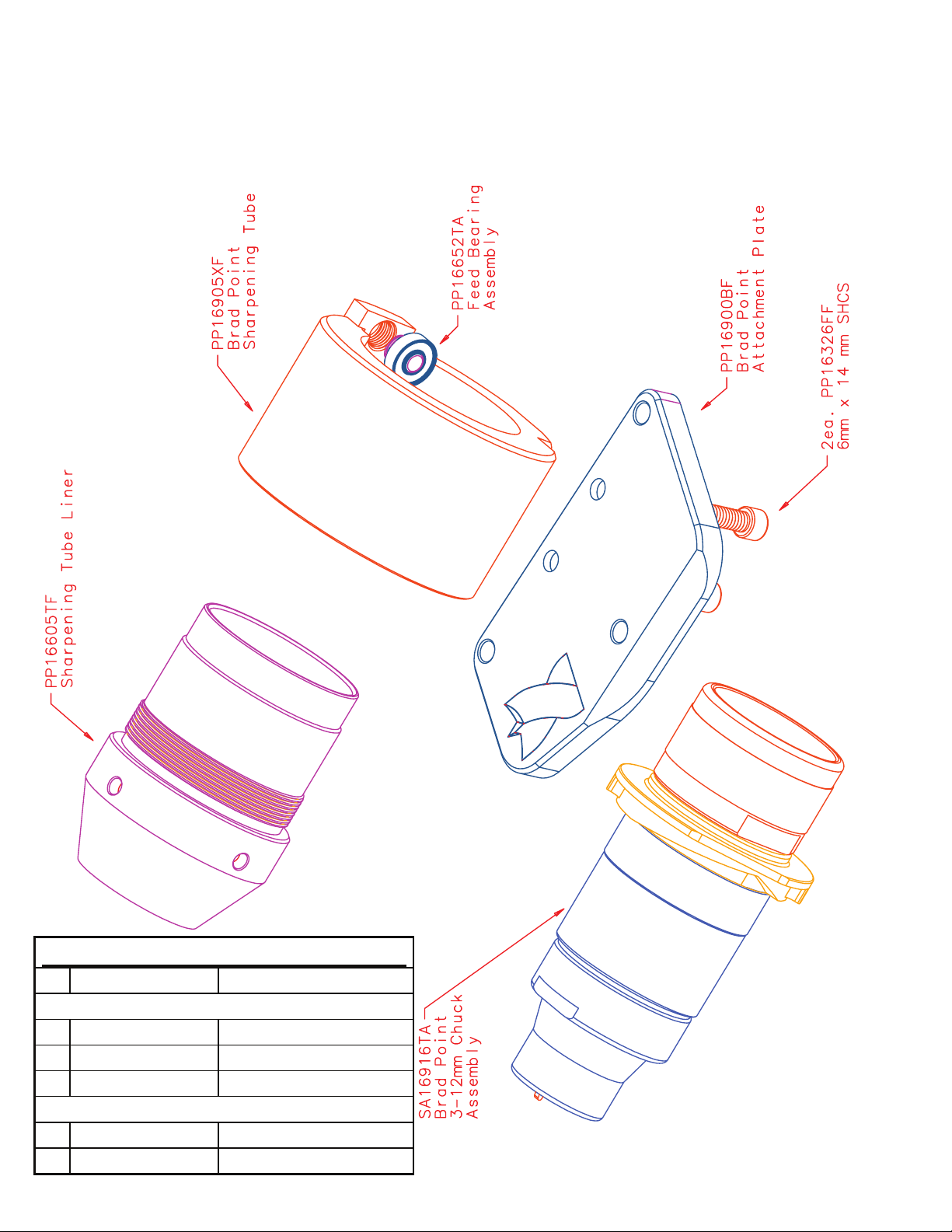
BRAD POINT ATTACHMENT
LEX200
Congratulations on the purchase of the Darex XT3000 Brad point Attachment. (LEX200) This
attachment consists of 2 pieces, 1 Sharpening
Fixture, SA16900BA and 1 - 3mm – 12mm Chuck,
SA16916TA. (The 12mm – 21mm Chuck,
SA16918TA is available
as an optional accessory)
Both components are
laser marked with a Brad
Point icon to minimize
confusion with other XT3000 attachments.
SETTING UP:
To sharpen a
Brad Point, you
will have to
remove the
standard
sharpening fixture
and replace it
with the X-Y
Table (LEX100).
The Brad Point Attachment works in conjunction
with the X-Y Table. By now you are familiar with
the ‘quick’ disconnect feature or your XT-3000.
Begin by removing the
current sharpening
fixture and replacing it
with the X-Y Table.
Secure it in place by
rotating the Docking
Lever CW. In much
the same manner,
secure the Brad Point
Sharpening Fixture to
the X-Y Table.
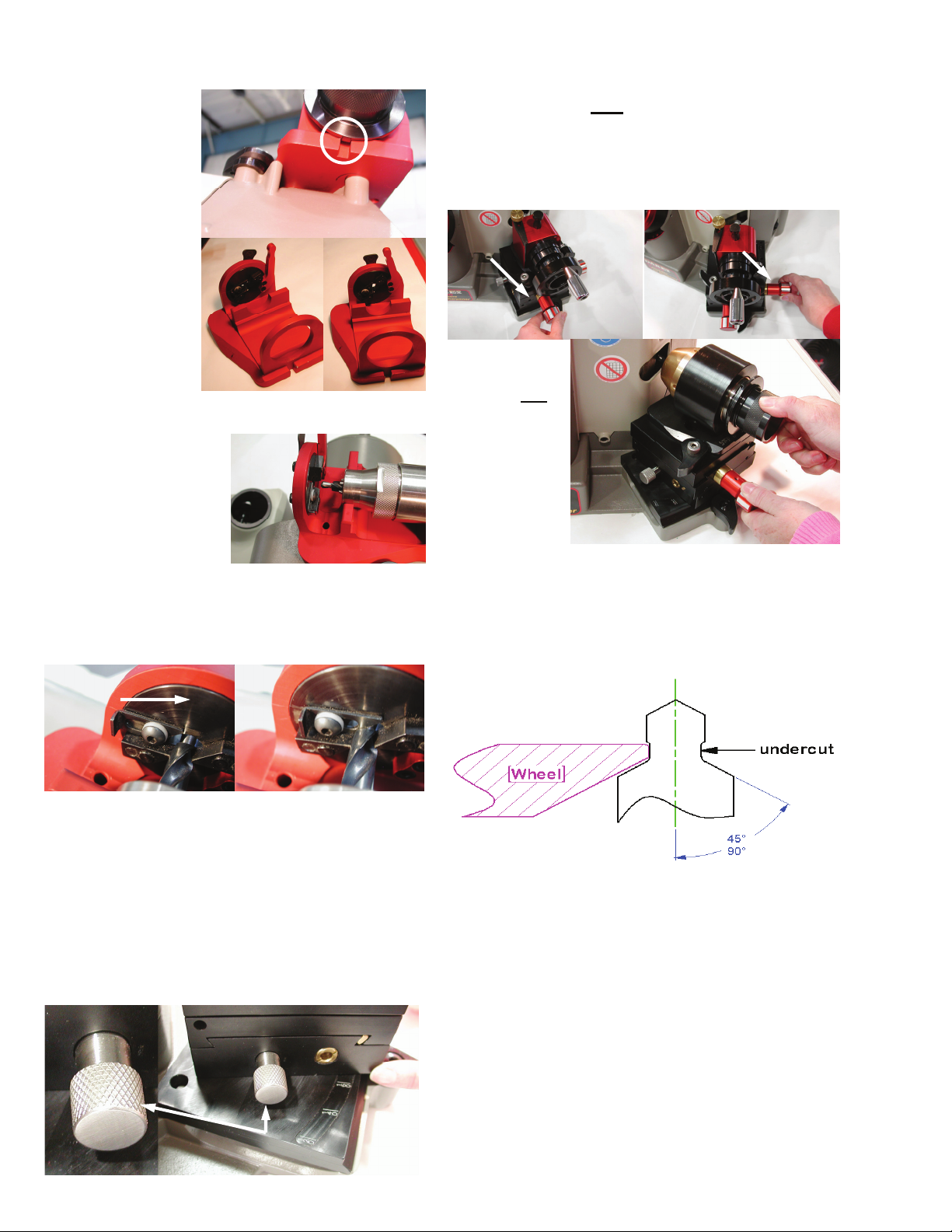
ALIGNING THE DRILL:
The alignment of the drill
happens in the XT-300
Alignment Tube. Loosen the
Timing Tube Lock lever
position
the Tube
@ 118°.
Push the
lever down
to lock the
tube. Align
the drill as
CORRECT INCORRECT
Pivot Lock Knob
0
X-Axis Knob
Y-Axis Knob
and
you normally would.
SETTING UP THE X-Y TABLE:
Brad point drills are ground with the X-Y Table
positioned at approx. the 160° mark. Loosen the
Pivot Lock Knob and rotate the X-Y Table to 160°.
Lock the Table.
Pivot Lock Knob
SHARPENING:
With the XT-3000
sharpening mechanism making sure the drill
DOES NOT
use the X-Y axis knobs to position the drill
the wheel.
Y-Axis Knob X-Axis Knob
ON
Turn
3000. Using the same
Axis Knobs, start to
move the drill into
the grinding wheel
while rotating the
Chuck. This fixture is
meant to re-sharpen
existing drills. During the sharpening process,
should you remove an
material, due to damage, it will be necessary to
re-align the drill and sharpen again. Refer to the
diagram
below for
examples of
proper drill
geometry.
contact the grinding wheel. If it does,
your XT-
OFF
, place the Chuck in the
excessive amount of
OFF
48
Page 51
Brad Point Attachment
Brad Point Attachment LEX200
SA11790PA
PP11745FF 1/4-20 x 1 SSS
PP11790PF Point angle lock knob
SA16652TA
PP16652TF Feed Bearing Bolt
PP08560LF Feed Bearing
49
Page 52

STEP DRILL ATTACHMENT
LEX 250
Congratulations on the purchase of your Darex
XT- 3000 Step Drill Attachment. (LEX250). This
attachment consists of 3 pieces, 1 Sharpening
Fixture, SA16950BA, 1 Alignment Fixture,
SA16970XA and a 3mm – 12 mm Chuck,
SA16975TA. (The 12mm – 21mm Chuck,
SA16980TA is available as an optional accessory)
All 3 components are laser marked with a Step
Drill icon to minimize confusion with other XT3000 attachments.
the XT-3000. Rotate the Docking Lever CW to
secure the X-Y Table to the XT-3000.
X-Axis Knob
Pivot Lock Knob
Y-Axis Knob
In a similar manner, lock the Step Drill Sharpening
Fixture on to the top of the X-Y Table. Secure the
Step Drill Alignment Fixture to the top of the XT-
3000.
SHARPENING THE PILOT
Should the pilot of the step drill need resharpened, do so, just as you sharpen a standard
twist drill. Having the exploded view drawing
handy will be beneficial at this point.
SHARPENING THE STEP
SETTING UP:
To sharpen the ‘step’ on your step drill, you will
have to remove the standard sharpening fixture
and replace it with the X-Y Table (LEX100). The
Step Drill Attachment works together with the X-Y
Table.
Rotate the
Docking Lever
CCW to free the
standard
sharpening
fixture, then
remove. Place
the X-Y Table on
ALIGNING THE DRILL:
Place the drill in the chuck and tighten chuck by
rotating the chuck knob CW. Stop just before the
chuck jaws make contact with the drill. Make sure
the drill still slides easily through the chuck. Place
the Chuck in
the Alignment
fixture until
the shoulder
of the chuck
stops against
the
alignment.
50
Page 53
Rotate the Chuck
until one of the
alignment dogs rests
firmly against the
Alignment.
Rotate the Pawl
Locating Cam until
the arrow lines up to
the major diameter
of the drill. As
indicated by the logo
on the Timing Arm,
rotating it will have
an impact on the
amount of relief
ground on the drill. Unless the drill is intended for
a unique material, it is
our recommendation
that it stay in its normal
location. Push the drill
through the chuck until
the pilot starts to pass
through the Alignment.
Slide the Length Setting Pawl until it almost
touches the pilot. Continue to slide the drill
through the chuck until the major diameter stops
against the Length Setting Pawl.
With the XT-3000
Sharpening Fixture making sure the drill is clear of
the grinding wheel. Using both the X and Y axis
knobs, position the drill close to, but not touching
the wheel.
Y-Axis Knob X-Axis Knob
Now, turn your
machine
Continue to
position the
drill into the
wheel while
rotating the
chuck.
It will be
necessary to
slightly undercut the pilot of the step drill to
produce a sharp corner at the end of the pilot
and beginning of the step.
Refer to the diagram below.
ON
OFF,
Slide the chuck into the
.
Rotate the drill CW until the cutting edges align
with the pawls. The drill is now set to length and
oriented to the chuck cam. Tighten the chuck and
ve it from the Alignment.
remo
SETTING UP THE X-Y TABLE:
Utilizing the X-Y Table, the angle ground into the
step portion of the drill can be 90°-180°. Loosen
the Pivot Lock Knob and slide table to the desired
angle. Tighten the knob.
Pivot Lock Knob
51
Once you are satisfied with the results, turn the
cross feed knob with your right hand CCW to
remove the drill from the grinding wheel. Carefully
remove the chuck from Sharpening Fixture. The
sharpening is now complete. During the
sharpening process, should you remove an
excessive amount of material, due to damage, it
will be necessary to re-align the drill and sharpen
again.
Page 54

Step Drill Attachment
52
Page 55

Step Drill Attachment SA16950BA
SA16652TA Feed Bearing Assembly
PP16652TF Feed Bearing Bolt
PP08560LF Bearing
SA03413BA Pawl Assembly
PP03440FF 10-24 Nylon hex nut
PP03435FF #10 nylon washer
PP03420TF Pawl Retaining Pin
PP03415TF Pawl Guide Pin
PP03412BF Pawl
Step Drill 3mm-12mm Chuck
SA16975TA
Step Drill 3-12mm Chuck
PP16400TF 3-12mm Body
PP16975TF Step Drill 3-12mm Cam
PP16410TF 3-12mm knob
PP16415TF 3-12mm closing sleeve
PP16420TF 3-12mm closing screw
PP02404SF Thrust Washer
PP16425SF 3-12mm - 12-21mm jaws
PP16442FF snap ring
PP16430TF Jaw guide
PP16435LF 3-12mm Jaw race
PP12560RF 3-12mm jaw springs
PP16440FF Jaw key screw
53
Page 56

90º - 120º Drill Attachment
LEX300
Congratulations on the purchase of your Darex
XT-3000 90°-120° Sharpening Attachment. As
part of the assembly you should have a
Sharpening fixture (SA16995XA) and Drill Chuck
(SA16890TA) range 3mm to 12mm. (SA016880TA
12mm to 21mm chuck available as optional
accessory.)
By now you are familiar with the ‘quick disconnect’
feature of your
XT-3000. Start
by replacing the
current fixture
with the 90°120°
attachment.
Set your desired
point angle by
pulling the red
Pivot Lock Lever
(counter
clockwise)
towards the
operator
and
sliding the fixture across the base plate to the
desired point angle.
Lock the fixture by returning the red Pivot Lock
Lever to its original position.
Use the XT-3000
alignment tube to align the
drill in the same manner
that you are accustomed to.
If the desired point angle
is 90°, the alignment tube
should be positioned at
118°. For other angles
using this attachment,
walk the alignment tube
towards or past 135° until
the correct chisel edge is
produced.
CORRECT INCORRECT
Remove the Chuck.
Gently slide the Chuck into the Sharpening fixture.
While keeping the Swing Cam in contact with the
Swing Cam Bearing, apply slight pressure into the
Grind wheel and rotate the chuck clockwise. Try
to sharpen the drill in such a manner that the drill
is off the wheel before you reposition your hand
on the Chuck Knob. Grinding time will vary
depending on wheel condition and amount of
material removal. It should require a minimum of
8-10 rotations. NOTE: If your drill does not touch
54
Page 57
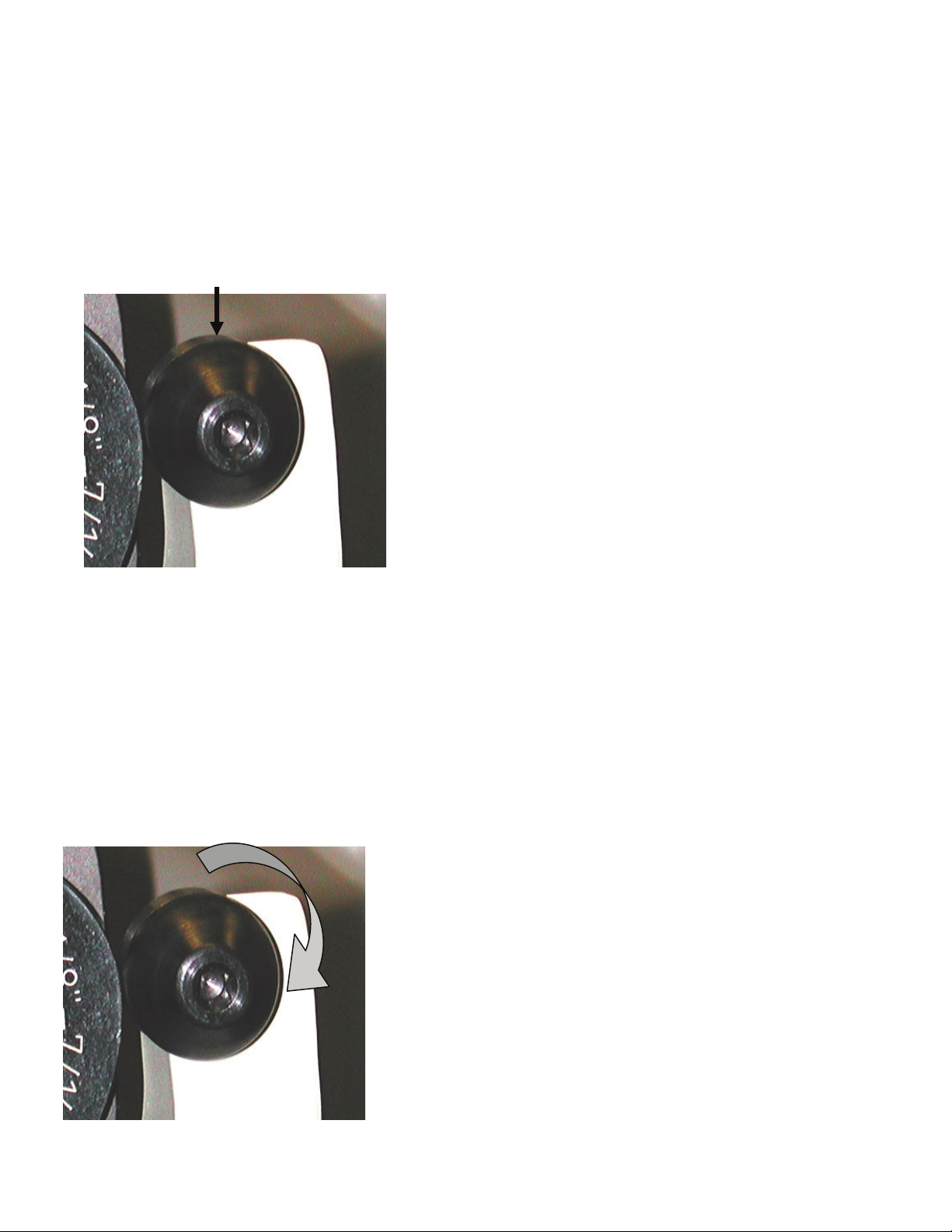
90º - 120º Drill Attachment
LEX300
the wheel, an adjustment to the Swing Bearing
Assembly will need to be made. Loosen the
Swing Bearing Assembly located on the Pivot
Base Casting. Rotate the Swing Bearing Assembly until the locating dot is positioned at 12oclock.
This bearing assembly is eccentric. The swing
cam on the chuck rests and rides on this bearing. When rotated, the relationship between the
chuck cam and the bearing change the starting
and stopping point of the drill bit. Depending in
which direction you rotate the bearing you will
move tip of the drill either closer to, or further
from the angle of the grinding wheel. This will
change the amount of material removed from
the end of the drill. To increase the amount of
material removed, slightly rotate the bearing
clockwise.
To decrease the material removed rotate the
bearing counterclockwise.
After adjusting, be sure to retighten, securing the
Swing Bearing Assembly. Re-sharpen the drill and
verify the corrected amount of material has been
removed. If incorrect, repeat procedure until the
desired amount has been removed. Approximately .010 should be the total amount of material removed during sharpening.
55
Page 58

90º - 120º Sharpening Attachment
56
Page 59

90º - 120º Sharpening Attachment
90°- 120º Attachment
SA16652TA Feed Bearing Assembly
PP16652TF Feed Bearing Bolt
PP08560LF Bearing
SA16615BA Pivot Lock Lever Assembly
PP16615BF Pivot lock lever
PP16630FF 5mmX8mm SSS
SA16657TA Swing Bearing Assembly
PP16655LF Swing Bearing
PP16657TF Swing Bearing Bolt
SA16645TA Spring Tensioner Assembly
PP16645TF Spring Tensioner
PP12280FF M6 x 1 x 8mm SSS
SA16890TA
3-12mm 90° Chuck
PP16400TF 3-12mm body
PP16890TF 90° 3-12 mm Cam
PP16410TF Knob
PP16415TF Closing sleeve
PP16420TF Closing screw
PP02404SF Thrust Washer
PP16425SF Jaws
PP16430TF 3-12mm jaw guide
PP16435LF 3-12mm jaw race
PP12560RF Jaw springs
PP16440FF Jaw key screw
57
Page 60

Mini Attachment
LEX350 & LEX351
Material Take off Adjustment for SA16401TA (1.5-7mm Chuck):
Small diameter bits have a high possibility of
breaking if too much pressure is put on them.
For this reason, it is critical to follow all of the
safety warnings in the XT 3000 User’s
Manual. In particular, it is very important to
wear ANSI certified (impact resistant) goggles
when sharpening small bits!
To minimize the risk of breaking bits, burning
them because of too much material take off,
or creating negative relief on the small bit,
the Small Chuck is designed to have a very
small Material Take Off (MTO). It will operate
only at the high end of the Material Take Off
(MTO) adjustment range.
This minimizes
Calibrating the Material Removal Knob
1. At the rear of the machine base, there is
a small access hole.
the possibility of a user accidentally trying
to remove 0.015” or 0.025” of material and
ruining a
been tuned for low MTO, it is possible that
your XT3000 may be adjusted out of working
range. If a drill bit mounted in the Small
Chuck, and then aligned at maximum MTO
(meaning the MTO knob is fully
counter-clockwise) does not touch the grinding
wheel, then you will need to adjust the
Material Removal knob to allow additional
material take off. Simply follow the instructions
from page 23 of the User’s Manual, which are
partly re-printed below.
small bit. Because the chuck has
2. Insert a 5/32 Allen wrench into the
access hole.
3. To retract the pusher shaft cap, increasing the amount of drill stick out, rotate
the wrench counterclockwise.
4. Each 1/4 turn will adjust 0.010”
(0,25mm) or one full turn will adjust
0.040” (1,0mm). After adjusting the
pusher shaft assembly, realign the drill
and remeasure the amount of stick out.
Repeate steps 2-4 until the system
removes approximately 0.005” (0,12mm)
of material from the small drill.
58
Page 61

Notes:
59
Page 62

Notes:
60
Page 63

XT3000
Auto Sharpening
Attachment
Auto Specification Sheet....................................................................... page 62
Quick Start Instructions ....................................................................... page 63
Attaching Auto Sharpening Fixture to XT-3000.................................... page 64
Auto Controller/Display Details............................................................ page 70
Alignment Instructions............... ........................................................... page
Auto Sharpening Fixture Details........................................................... page 75
Auto Sharpening Fixture Parts List....................................................... page 78
Auto Sharpening Fixture Schematic ..................................................... page
Geared Chuck Parts List ....................................................................... page 80
Geared Chuck Schematic ...................................................................... page 81
Auto Controller/Display Parts List ........................................................ page 82
Auto Controller/Display Schematic ...................................................... page 83
Maintenance ........................................................................................ . page 84
Trouble Shooting Guide ........................................................................ page 86
74
79
*For Technical Service visit our web site at darex.com
Or call Darex at 800-547-0222
Or contact your Darex Distributor
Page 64

Auto Sharpening Attachment Specification Sheet
B
A
C
XT-3000 Auto Sharpening Attachment
Specifications
Warranty - 1 year on defective parts
A) Geared Chuck:
Chuck Body Material - 303 Stainless
Knob and Cam Material - 12L14
Capacity - 3mm - 12mm or 12mm - 21mm
Gear Spline - 45 Tooth
Weight - 2.1lbs each (0.95kg)
B) Sharpening Fixture:
Gear Material - Acetal;
Gear Motor - 12 VDC, rated current 350 mA, typical current 150 mA
Home switch - Slotted Optical
Weight - 6.0 lbs ( 2.72 kg)
C) Controller/Display:
Housing Material - Glass filled, Acrylonitrile Butadiene Styreme (ABS)
STN Graphic LCD w/ Green LED back light
Weight - 1.5lbs (0.68 kg)
Power Inlet:
Voltage: 115v~ Voltage: 115v~
Frequency: 60hz Current : 8A Max
Current: Fusing : 8A Time Lag
Grind Motor: 3.2A
Accessory: 8.0A
Power Outlet:
62
Page 65

only
this
will immediately start the grinding
wheel in motion
Quick Start Set Up
The Auto Sharpening Attachment comes
equipped with a sharpening fixture, a
Controller/Display and a chuck/chucks.
Available chuck options listed below. The
Automated Sharpening System is for
use with the XT-3000 Expandable
Tool Sharpener
with other sharpeners.
LEX400 - 115v w/3-12mm Chuck
LEX400I - 230v w/3-12mm Chuck
LEX450 - 115v w/12-21mm Chuck
LEX451I- 230v w/12-21mm Chuck
LEX500 - 115v w/3-21mm Chucks
LEX500I- 230v w/3-21mm Chucks
1. Remove from shipping box and remove all packaging material.
2. Attach sharpening fixture to XT base,
making sure the sharpening fixture is
secure. For more information on
mounting the sharpening fixture, see
page 9.
3. Attach Controller/Display with mounting bracket provided, see page 10.
4. Connect DIN cable from sharpening
fixture to Controller/Display, see page
12.
5. Connect power from outlet source to
back of Controller/Display inlet, see
page 13.
6. Connect Pigtail Jumpers from the
back of Controller/Display to XT-3000
Base casting inlet. For detailed set up
information, see page 13.
7. The accessory receptacle is located at
the top of the power receptacle on th
back of the Controller/Display and wi
allow you to use a dust extraction system in conj
XT3000. *We highly recommend
the use of a vacuum when the
machine is in use.
8. Make sure the grit tray is in place and
secure.
unct
and not for use
ion with the use of th
ll
e
9. Un-box the chuck.
10. Align and secure the drill in the chuck.
(See XT-3000 Instruction Manual
PP16180KF for Alignment details)
11. Insert chuck into Sharpening fixture.
Secure chuck in sharpening fixture.
12. Power on the machine by pushing the
rocker switch into the ON position,
Controller/Display screen.
13. Set up the LCD screen on the Controller/Display, see pages 15-18.
14. (THIS STEP IS NOT NECESSARY
WHEN PURCHASING AND XT-3000
A COMPLETE) Calibrate Final Grind -
Drill Stick Out on sharpening fixture, see
pages 20-21.
15. Press Start on the Controller/Display
screen to begin sharpening. NOTE: The
e
sharpening fixture will immediately begin to rotate and sharpen the drill. Make
sure hands and clothing are free of the
sharpening fixture.
16. Once the chuck has stopped, release
the chuck and remove from sharpening
fixture.
17. If a split point drill is desired, insert
chuck into splitting port. DO NOT remove drill from chuck until split is complete. (See XT-3000 Instruction Manual,
PP16180KF, for Split Point details)
and power up the
63
Page 66

Automated Sharpening Attachment
Attaching Sharpening Fixture to
Base Casting:
Make sure all contact areas are clean and free
of metal dust.
1. Rotate the locking lever so the flat edge is
on top, horizontal and in a
straight line
with the base
casting.
2. Position the
sharpening fixture so that the 2 location holes
on the base of
the alignment
fixture are
aligned with
the 3/8 dowel
pins.
3. After sharpening fixture is in place, rotate
the locking lever clockwise until snug. This will
secure the sharpening fixture to the base.
64
Page 67

Mounting Auto
Controller/
Display to
Base Casting:
1. Install and tighten
the two, 6mm BHSHC
screws from the stamped bracket to the control
box.
2. Align control box to main casting and transfer
punch or mark for drilling mounting screw holes.
5. Peel adhe-
sive backing
from dual-lock
tape.
6. Carefully
align Controller/
Display to XT
base casting
and press
firmly.
3. Drill through
casting.
Caution don’t drill into motor housing
4. Using the alcohol wipe provided, thoroughly
clean the XT base casting surface where the adhesive will make contact.
5. Using 2, 10-24 thread forming screws,
insert into mounting bracket. While pushing hard, drive
in screws until
seated.
65
Page 68

Important: Be sure you have the DIN pins
and receptacle aligned correctly before engaging. Improper connection can result in
a blown optical switch in the sharpening
fixture which will make the unit nonfunctional.
Automated Sharpening Attachment
Connecting Sharpening Fixture to
Controller/Display:
1. Connect the mini DIN power cable coming fro
the Sharpening Fixture to the mini DIN receptacle located slightly underneath the bottom of the Controller/Display.
66
Page 69

Caution: Only one supply source can
be connected to this equipment!
Caution: Do not connect a separate
power source to this Inlet!
Automated Sharpening Attachment
Connecting Auto Controller/
Display to XT-3000:
1. Located on the back of the XT-3000 base
casting is the secondary power receptacle.
2. The secondary accessory receptacle is located on the top and
the secondary power inlet is located on the bottom of the receptacle.
Connecting AC Power to Auto
Controller/Display:
1. Located on the back of the Controller/
Display is the primary power receptacle.
Within this receptacle you will find a power
inlet and accessory receptacle.
3. Connect
both pigtail
jumpers
coming from
the Controller/Display to
the appropriate positions
in the secondary receptacle located at the back of the XT-
3000.
2. Provided with the XT-3000 is a power cord.
Plug the cord into to a power outlet and into
the power inlet located on the back of the
Controller/Display.
67
Page 70

Vacuum Receptable
Power Connections - Back View
Automated Sharpening System
To Power Source
From Controller/Display
From Controller/Display
68
Page 71

Automated Sharpening Attachment
Connecting Vacuum:
The accessory receptacle on the back of the
Controller/Display is located in the
top position on the receptacle. This
will allow you to connect a dust
extraction system to be used during sharpening.
*We highly recommend the
use of a dust extraction system
when the auto sharpening system is in
use. DAREX offers a vacuum system compatible with your XT3000.
Call DAREX for pricing.
• SA12075EA - 115V Vacuum
• SA12072EA - 230V Vacuum
Grit Tray/Vacuum Port Connection:
Grit tray
At the back of the machine, located underneath
the grinding motor is
the grit tray. Drill
grindings will
accumulate inside the
grit tray. The grit tray
has a magnetic liner
to attract and hold
these dust particles.
Do not let the tray
become more than
1/3 full.
Vacuum Port Connector
(Optional)
The grit tray has a knock out plug that can be
removed by hand
and replaced with
the vacuum tube
(SA16030TA).
Use this port to connect a vacuum hose to
the XT3000. This method of extracting dust
particles from
the machine
will keep it
cleaner and is
recommended.
Make sure the grit tray is in place and secure
before connecting the
vacuum hose.
To remove tray, unscrew brass thumb screw.
Remove tray and dump contents. Wipe excess
dust from the tray
with a rag.
69
Page 72

Display Details
CYCLE START/SELECT/SAVE:
CYCLE STOP/STOP/EXIT:
ARROW UP:
To operate the Auto Attachment you must first
power up the XT-3000 sharpener. Once powered up, the grinding wheel on the XT-3000
will begin to turn at full speed and the Controller/Display screen will illuminate.
To access the complete menu, touch
the System Settings button located
on the left of the screen.
This will display the full menu:
• Clean Up Turns
• Auto/Manual Select
• Reset Bit Count
• Language Selection
• Motor Stall Delay
• Grind Sensitivity
• Factory Bit Count
• Software Version
ARROW DOWN:
SYSTEM SETTING:
Use the Arrow up and Arrow down buttons to view the entire menu. When
the text of the menu option has
changed to bold, the secondary menu
option can be accessed.
To select and enter into each secondary menu
touch
Pressing will allow you to exit the
sc
reen you are working in.
70
Page 73

Display Details
CLEAN UP TURNS:
By selecting “Clean up turns”,
The display shows:
The “Clean up turns” is active only when in “Auto”
Sharpening mode.
Pressing “Arrow up” advances clean up pass
by one.
Pressing “Arrow down” reduces pass by one.
Pressing “Save ”, stores and exits.
Pressing “Exit”, exits without saving.
AUTO/MANUAL SELECT:
By selecting “Auto/Manual”,
The display shows:
Pressing “Save ”, stores and exits.
Pressing “Exit”, exits without saving.
AUTO:
By selecting “Auto”,
The display shows:
When “start” is pressed, the
sharpening fixture will begin to
sharpen.
During sharpening, you will see the number of rotations on the screen increase.
When the grind is complete, the programmed cleanup passes will appear and
begin to count down to 0. The sharpening
port will rotate to the home position and
stop.
At the end of each sharpening, the Bit
Count increases.
Pressing “Arrow up” or “Arrow down”
will highlight each menu option.
By pressing “stop” during the Auto
Cycle the unit stops and returns home.
71
Page 74

Display Details
MANUAL:
By selecting “Manual”,
The display shows:
By pressing “Arrow up”, the number of
Manual turns increases.
By pressing “Arrow Down”, the number
of Manual turns is decreased.
This automatically saves the new setting.
RESET BIT COUNT:
By selecting “Reset Bit Count”,
The display shows:
Pressing “Arrow up”, or
“Arrow down”, will highlight each menu
option.
Pressing “Save”, resets the bit count,
only, if the “yes” is highlighted.
After pressing “Start”, the manual
sharpening begins.
The display starts counting down the number
of turns. At the end of sharpening, the Bit
Count increases.
By pressing “Stop”, the manual sharpening ends.
Pressing “Exit”, exits without saving.
LANUGUAGE SELECTION:
By selecting “Language Option”,
The display shows:
Pressing “Arrow up” or “ Arrow down”
will highlight each language option.
72
Page 75

Display Details
Pressing “Select”, displays language selection and exits.
Pressing “Exit”, exits without saving.
MOTOR STALL DELAY:
This screen will appear on the display:
The Grind Sensitivity is a measure of how
quickly the controller responds to the material take off during AUTO grinding. A
lower number generally creates more
turns, a higher number means
fewer turns before the controller decides it
has reached the proper material removal.
This variable is set at a factory default of
25. When Darex CBN and Diamond wheels
are used, the setting of 25 is appropriate
and will not need to be changed.
FACTORY BIT COUNT:
“Motor Stall Delay is used to detect a prolonged
period of the Gear Motor not turning, sensing a
blocked or jammed condition. The available settings are 2, 3 or 4 seconds; the factory default
is 3 seconds.
If the unit detects a 3 seconds lapse and the
chuck has not rotated at least a half turn, the
unit will shut itself off and “Sharpening Interrupted” will appear.
The system will reset itself.
.GRIND SENSITIVITY:
This screen displays the accumulative
number of times the cycle start button has
been pressed. This number cannot be reset and will be used for warranty evaluations.
SOFTWARE VERSION:
This screen displays the current version of
software. You will need to know the software version for upgrade status and
troubleshooting.
73
Page 76

Alignment Instructions
Each chuck has
an orientation
line scribed on
the chuck dog
of the cam.
To achieve the highest level of concentricity, in the
alignment step, insert the chuck with the white line up.
74
Page 77

Auto Sharpening Fixture
SECURE CHUCK IN SHARPENING FIXTURE
After the drill has been properly aligned and
secured in the chuck, be sure to lock the chuck
into the automated sharpening fixture.
Located on the front of
the sharpening fixture
is a spring loaded handle assembly.
This is the “Cam Follower” assembly.
Grip the Cam Follower
“Knob”, rotate the assembly as far clockwise
as possible.
Insert chuck into
sharpening port
with the white line
on the dog,
aligned
with the locating mark on the face of the
sharpening tube housing.
This will allow you
to insert the chuck
into the sharpening
tube without interference.
75
Page 78

IMPORTANT: This step is NOT necessary
for the XT-3000-A & XT-3000I-A Complete.
Auto Sharpening Fixture
Gripping the
follower “Knob”,
gently pull back
and rotate the
“Cam Follower”
assembly as far
counterclockwise as possible.
Release the “Knob”.
This will secure
the chuck in the
sharpening fixture.
To remove the
chuck, wait for
the sharpening fixture to come to a
complete stop. Simply rotate the “Cam
far clockwise as possible.
NOTE: It is not necessary to pull back
when rotating the “Cam Follower” assembly
clockwise.
DRILL STICK OUT- FINAL GRIND:
The Drill Stick Out - Final Grind amount on the
Auto Sharpening system must be calibrated to
produce the same Drill Stick Out - Final Grind
amount as produced on your existing Manual
Before you begin sharpening with your Auto
system, take the time to calibrate Final Grind-
Drill Stick Out. This will help retain your cur-
rent point split depth calibration.
Verify Final Grind Drill Stick Out On Manual
System First:
1. Rotate material removal knob
to minimum take off setting.
2. Align drill in chuck. Once drill is
set to length, aligned and
securely captured in the chuck, remove from
alignment port.
3. Using a height gauge,
measure the amount of
drill protruding from the
end of the chuck to the
tip of the drill. (Drill
Stick Out - Before Grind)
4. Sharpen the drill
until spark out has
been achieved.
Remove chuck from
sharpening port. Without removing
the drill, re-measure the
amount of Drill Stick Out
after grinding. Your
Auto system must be adjusted to produce the
same Final Grind - Drill Stick Out measurement as the manual system.
as ylbmessa ”rewolloF
5. Remove the Manual System and install the
Auto Sharpening System.
6. Using the same drill bit, repeat steps 1-4 to
determine the Final Grind - Drill Stick Out
measurement currently produce by the Auto
Sharpening Syste
You will need to adjust the Swing Bearing
assembly on your Auto sharpening attach-
to duplicate the Final Grind - Drill Stick
ment
Out measurement produced by the Manual
system, see page 21 for calibration details.
76
m.
Page 79

Auto Sharpening Fixture
CALIBRATING DRILL STICK OUT - FINAL
GRIND :
The swing cam on the chuck rests and rides
on the Swing Bearing assembly. This bearing
assembly is eccentric. The Auto Sharpening
Fixture will arrive with this bearing positioned
so that the drill will NOT make contact with
the grinding wheel. By repositioning the bearing, the amount of material removed from the
end of the drill will change, changing the Final
Grind - Drill Stick Out amount.
1. Using a 3mm hex
wrench, loosen the
Swing Bearing Assembly, located on
the back of the Pivot
Base Casting.
2. To increase the amount of material removed from the end
of the drill and reduce the Drill Stick
Out amount, slightly
rotate the bearing
clockwise.
3. After repositioning the bearing, be
sure to retighten the assembly bolt, securing
the new position of the Swing Bearing Assembly.
4. Sharpen the drill and verify the amount of
Final Grind - Drill Stick Out.
Repeat this procedure until the Final Grind
Drill Stick Out amount measures the same as
ced with the Manual system.
produ
Once the Final Grind - Drill Stick Out has been
calibrated, it will not be necessary to make
this adjustment again.
-
77
Page 80

Auto Sharpening Fixture Parts List
SA17050TA Auto Sharpening
Fixture Complete
1) - PP17128PF Gear Cover
2) - SA17121TA Drive Gear Assembly
3) - PP17125MF Gear Motor
4) - PP17131PF Motor Cover
5) - SA17145EA Switch Harness
6) - SA16652TA Feed Bearing Assembly
7) - PP17065TF Gear Chuck Tube Liner
8) - PP12220FF 3mm x .5 x 6mm screw
9) - PP17075PF Park Cam Wear Plate
10) - SA16645TA Spring Tensioner Assembly
11) - PP16650RF Return Spring
12) - SA16615SA Pivot Lever Assembly
13) - PP16630BF Docking Plate
14) - SA16657TA Swing Bearing Assembly
15) - SA17085TA Follower Bearing Assembly
16) - PP17079FF 5mm x .8 x 16mm screw
17) - PP17078PF Follower Plunger Knob
78
Page 81

Auto Sharpening Fixture
79
Page 82

Geared Chuck - Auto
ITEM ITEM_DESC
)LANOITPO( KCUHC DERAEG MM21-3 AT01071AS
1) - PP17013TF
2) - SA12565RA
3) - SA16425SA
4) - SA17018TA
5) - PP16442FF
6) - PP16440FF
7) - PP16420TF
8) - PP16435LF
9) - PP16430TF
ITEM ITEM_DESC
3-12MM GEARED CHUCK BODY (B BP S N)
CHUCK JAW SPRINGS (5 PIECES)
JAW SET (5 PIECES)
3-12MM GEARED CHUCK CAM/KNOB ASSEMBLY
3-21MM SNAP RING
JAW KEY SCREW
3-12MM CLOSING SCREW
JAW RACE
3-12MM JAW GUIDE (B BP S N)
)LANOITPO( KCUHC DERAEG MM12-21 AT52071AS
1) - PP17030TF
2) - SA12567RA
3) - SA16427SA
4) - SA17040TA
5) - PP16442FF
6) - PP16440FF
7) - PP16418TF
8) - PP16470LF
9) - PP16465TF
12-21MM GEARED CHUCK BODY (B BP S N)
CHUCK JAW SPRINGS (7 PIECES)
JAW SET (7 PIECES)
12-21MM GEARED CHUCK CAM/KNOB ASSEMBLY
3-21MM SNAP RING
5MM X .8MM X 10MM SSS
12-21MM CLOSING SCREW (B BP S N)
12-21MM JAW RACE
12-21MM JAW GUIDE (B BP S N)
80
Page 83

Geared Chuck - Auto
81
Page 84

Controller/Display Parts List
SA17060TA Auto Controller/Display
115V Complete
SA17061TA Auto Controller/Display
230V Complete
1) - SA17230EA Interface Harness Assembly
2) - SA17173TA Mounting Bracket Assembly
3) - SA17185EA Display Assembly
4) - PP117228PF Housing Main Side
5) - PP17231EA Interface PWB
6) - PP17180FF Dual Lock Mounting Tape
7) - PP17225PF Housing Base Side
8) - PP17190EF Display PMB w/LCD
9) - PP17195PF Display Housing
10) - PP17198EF Membrane Switch Panel
11) - PP17238EF 115V Relay
11) - PP17240EF 230V Relay
Not Shown -
PP17250FF
Not shown -
PP12057EF
Vacuum Fuse 115V
Vacuum Fuse 230V
82
Page 85

Controller/Display
83
Page 86

Maintenance
This unit will display a “Maintenance Alert“
when maintenance is required.
The screen will display:
Every 100 sharpenings this alert will appear as
a reminder to perform the required routine
maintenance listed below. Performing this
maintenance will keep the auto sharpening
fixture running properly and extend the life of
the components. It will also help prevent excessive grit build up which will cause premature sharpening interruptions.
This is a good time to inspect the rest of the
XT machine and perform any other necessary
maintenance, see page 30.
For best performance and longevity of
the Auto Sharpener we highly recommend the use of a dust extraction system.
For more information contact DAREX @
800-547-0222.
Once maintenance has been completed, using the “Arrow up” “Arrow
down” buttons, highlight “Yes”.
To select yes press the select button.
This will clear the “Maintenance Alert”
and you may resume sharpening.
1. Power off the machine, waiting to perform
the maintenance only once the grinding wheel
has come to a complete stop.
Disconnect the
power from the machine using a lock out tag
out procedure.
2. Vacuum any grit found on the machine.
Pay special attention to the electronic controller, the Follower Cam Tube Assembly and
Chuck Tube Liner.
NOTE: Do not use an air gun, as this can blow
grit into the Controller/Display housing or the
Follower Cam Tube Assembly on the s
ing port.
3. Use a clean, dry cloth to wipe down the
chuck bodies and the inside liner of the chuck
port. After using a dry cloth to clean these,
use the lubricated cloth, (gun cloth or similar)
provided, to re-apply a very fine lubrication to
these surfaces. (You can also use a clean cloth
with a light spray of silicone. Avoid aggressive
solvent based lubricants like WD-40.)
harpen-
84
Page 87

Maintenance
WHEEL MAINTENANCE
These wheels are maintenance free from truing
and dressing but will need to be cleaned periodically.
machine using a lock out tag out procedure. After removing the wheel from the
sharpener, saturate the wheel with any type of
oil-less solvent, such as Automotive Brake
Cleaner. It is helpful to use a soft bristle brush
and lightly brush the saturated wheel, loosening the impacted grinding particles. Re-saturate
the wheel to flush out any loosened debris. Do
not use any type of dressing tool on these
wheels. Damage to surface will occur and
greatly shorten the wheel life.
NOTE:
discolor or burn, the wheel life may be exhausted and the wheel will need to be replaced.
Disconnect the power from the
If after cleaning wheel, the drills still
CHUCK MAINTENANCE
The use of a dust extraction system during
grinding will help reduce the amount of maintenance, however, the chuck assembly should be
disassembled and cleaned periodically. See XT3000 instruction manual for detailed disassembly instructions.
GRIT TRAY
At the back of the XT-3000 machine, located
underneath the grinding motor is the grit tray.
Drill grindings will accumulate inside the grit
tray. The grit tray has
a magnetic liner to
attract and hold these
dust particles. Do not
let the tray become
more than 1/3 full. To
remove tray, unscrew
brass thumb screw.
Remove tray and
dump contents. Wipe
excess dust from the
tray with a rag.
Darex recommends the use of a dust extraction system when the Auto Attachment is in use.
85
Page 88

Trouble Shooting
The unit stopped working and the screen
displays “Sharpening Interrupted”:
• This message will appear if the user
presses the “Stop” button during sharpening. It will also appear if the controller detects a large load on the chuck turning
motor. This is typically caused by dirt or
grit accumulating on the Chuck Body,
Chuck Tube Liner, or the Cam Follower
Assembly. Turn the machine off and perform the standard maintenance procedures
listed on pages 29 & 30. Restart the machine and see if it runs without interruption. If the controller continues to show
this message, call Darex customer service
for assistance.
The display does not come on when I
plug the unit it:
• The auto controller receives its power
through the AC plugs in the rear of the
unit. Make sure there is power to the outlet you are using.
• Make sure the wiring on the back of the
unit matches that of the user manual
(power comes in to the controlle
both pigtails are
firmly seated between the
r, and
controller and the XT unit).
• Try unplugging and re-plugging these
cords to ensure they are well seated.
• Finally, make sure the on/off switch on the
XT-3000 machine is powered on. The display will not come on until you power up
the XT-3000. If unsuccessful, call Darex
customer service for assistance @ 800547-0222.
• If the optical switch in the Sharpening
Fixture is faulty, call Darex customer
service for assistance.
• Check the small cable coming from the
sharpening port to the Gear Motor.
• Finally, remove both covers on the Gear
Motor and Gear located on the Sharpening
Fixture. Verify the Drive Gear is secured to
the Gear Motor.
The unit powers up and runs the sharpening system, but the vacuum does not
come on:
• The vacuum receptacle for the Auto sharp-
ening system is located on the back of the
Controller/Display housing, see page 14.
Make sure this connector is firmly seated.
• The connector is fused with two 8A time
delay fuses (1.6A on the 230V international model). Make sure these fuses are
intact. If a fuse is found to be blown, then
both fuses should be replaced with the appropriate capacity. You can find the part
numbers for these fuses listed on page 26.
Note: U
not re
sing fuses not supplied by DAREX is
commended and may cause damage to
the Controller/Display.
If the grind motor starts but the Auto
Display is off:
• The internal relay may be defective. This
can be detected by checking for voltage at
the vacuum output receptacle with an
electrical meter.
The unit powers up, the display is on, but
pushing the “Start” button to sharpen
nothing happens:
• There is a cord that connects the sharpen-
ing port to the Auto Controller/Display,
see page 12. Be sure that the 5 pin DIN
connector on this cord is firmly seated into
the connector on the Controller/Display,
paying careful attention to cord/connector
orientation. Important:
See information
on page 67. Inspect the cable, coming from
the controller to the sharpening port,
for damage.
86
Page 89

Page 90

WORLD’S BEST SELLING INDUSTRIAL DRILL SHARPENERS
Phone:
800-547-0222
541-488-2224
Darex
P O Box 730
210 E Hersey St
Ashland, OR 97520
USA
Fax:
541-488-2229
Email:
techsupport2@darex.com
Web:
www.darex.com
PP16180KF Rev 4 7/13
 Loading...