

Page 1
Large Drill Attachment
LEX050
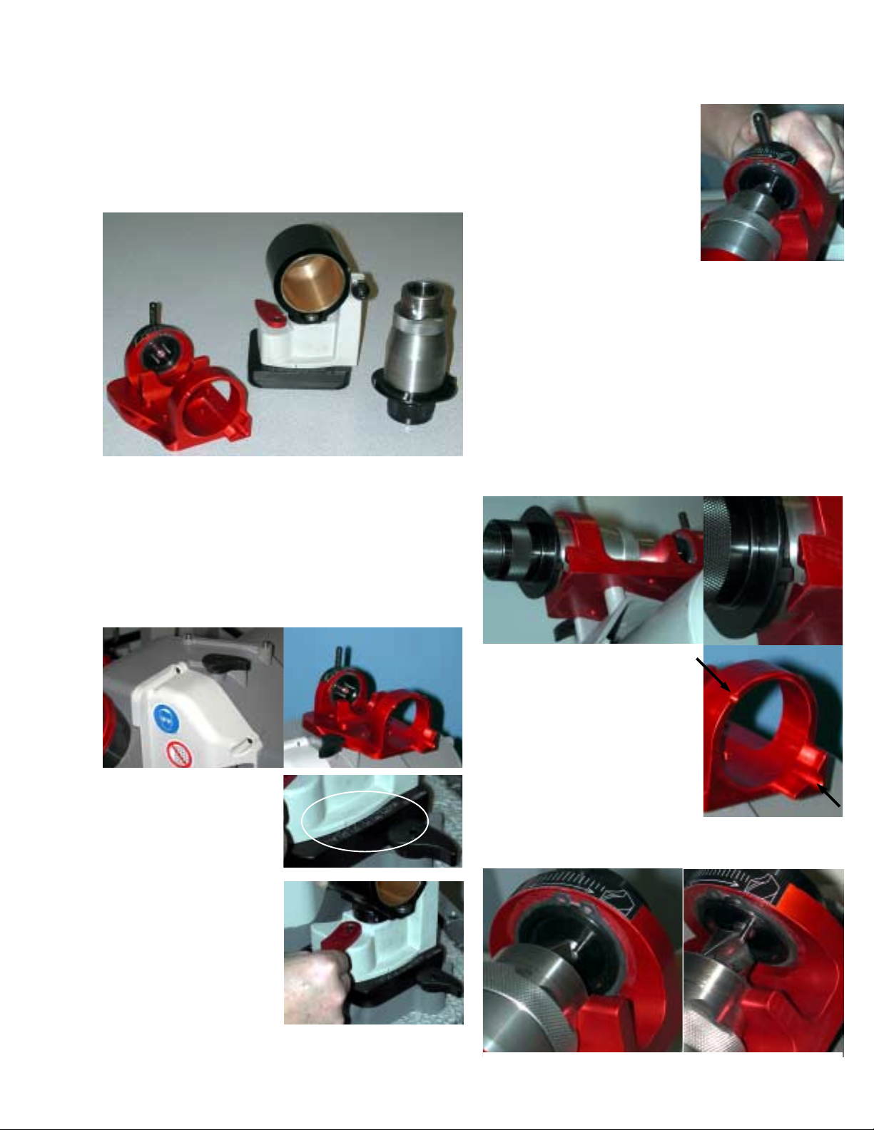
Congratulations on the purchase of your Darex
XT-3000 Large Drill Attachment. (21 mm—30
mm) As part of the assembly (see picture from
left to right) you should have a SA16565XA Large
drill alignment, SA16575CA Sharpening fixture,
and SA16500TA Large Drill Chuck.
By now you are familiar with the ‘quick disconnect’
feature of your XT-3000. Start by placing the
Large Drill Alignment on the top of your XT-
3000. Rotate the ‘Docking Lever’ clockwise to
securely lock the fixture in place. In a similar
manner, remove your current sharpening fixture
and replace it with the Large Drill Sharpening
alignment is adjusted by
rotating the black lever
located at on the front of the
alignment fixture. As per the
decal, rotating the lever
towards the operator will
reduce the amount of relief
ground onto the drill and
pushing the lever away from
the operator will increase the relief. Placing the
pin at the midway point on the decal is a good
starting place for 118° drills. For 135°-150° drills
start with the alignment 2 marks towards the
operator. You can set the alignment at any setting
necessary to achieve the amount of relief desired.
Place the drill in the chuck and turn the chuck
knob clockwise until the drill slides freely through
the chuck jaws. Next slide the Chuck and drill into
the alignment rotating the chuck until one of the
Fixture.
Now would be a great
time to determine the
point angle of the drill
that is to be sharpened
and adjust both the
sharpening fixture and
alignment to that point
angle. The Sharpening
fixture is adjusted by
pulling the red lever
towards (counter
clockwise) the operator
and sliding the fixture to
the point angle desired. Lock the fixture by
returning the red lever to its original position. The
‘cam dogs’ aligns with the
mating ‘notch’ in the fixture.
You will notice the opposite
‘dog’ aligns with a reference
mark machined into the
alignment fixture.
Now push the drill through the chuck until it
contacts the stop. Rotate the drill clockwise until
Incorrect Correct
41
Page 2
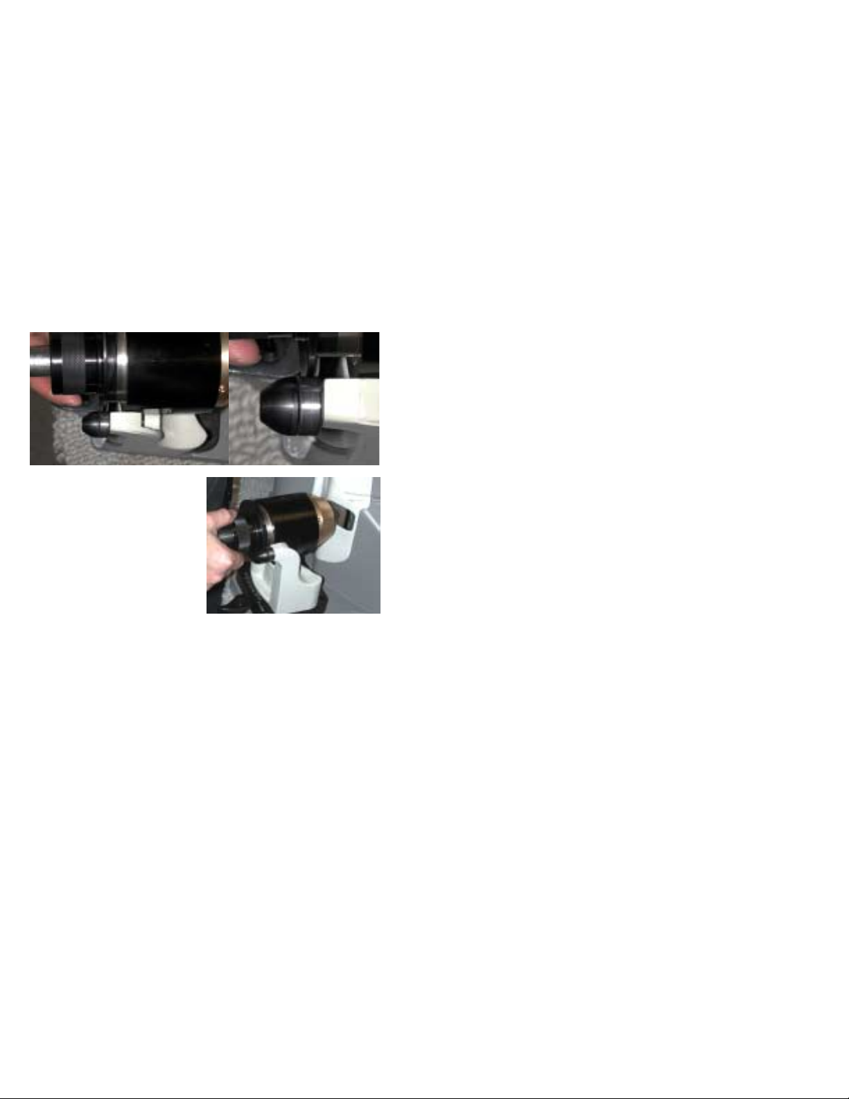
the outer edge of the cutting lip is touching the
pins in the setting fixture.
Firmly tighten the chuck by turning the knob
clockwise while the chuck is still in the fixture.
Remove the chuck and drill. The drill is now
aligned and set to length to the chuck cam for the
necessary grinding.
Slide the chuck into the Sharpening fixture and
rotate the Chuck clockwise applying slight
pressure into the wheel. It is also necessary to
keep the cam up against the swing cam follower
bearing.
Try to sharpen the drill
in such a manner that
the drill is off the wheel
before you reposition
your hand on the chuck.
Grinding time will vary depending on wheel
condition and amount of material removal but it
should require a minimum of 8-10 rotations.
NOTE: The MTO drill stop setting is adjustable
using a 5/32” or 4 mm hex key if you think more
or less material removal is desired.
Please Note, you do not have the ability to split
drills from 21 mm to 30 mm on the XT-3000.
42
Page 3
Large Drill Attachment
43
Page 4

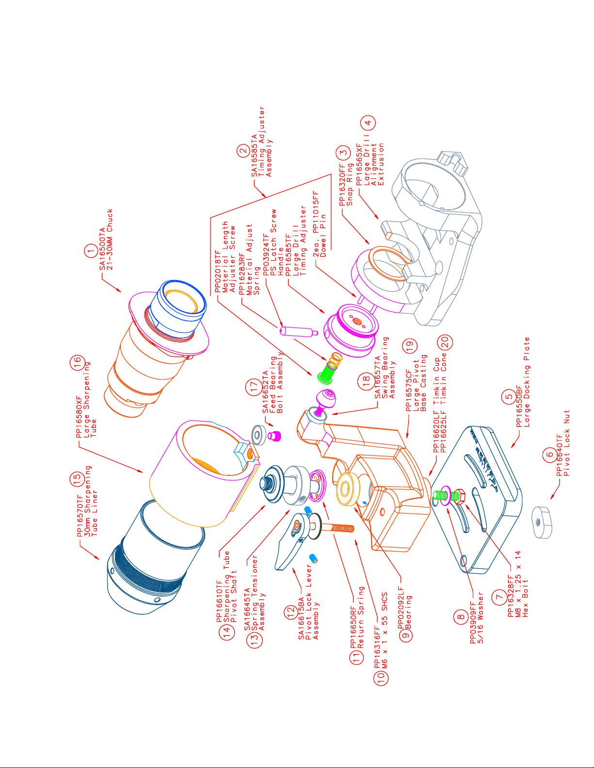
Large Drill Attachment LEX050
SA16615BA Pivot Lock Lever Assembly
PP16615BF Pivot lock lever
PP16630FF 5mmX8mm SSS
SA16585TA Timing Adjuster Assembly
PP16283RF Material adjust spring
PP16285TF Material adjust screw
PP03924TF PS Latch Screw Handle
PP16585TF Large Drill Timing Adjuster
PP11015FF 1/8" Dowel Pins
SA16652TA Feed Bearing Assembly
PP16652TF Feed Bearing Bolt
PP08560LF Bearing
SA16657TA Swing Bearing Assembly
PP16655LF Swing Bearing
PP16657TF Swing Bearing Bolt
SA16645TA Spring Tensioner Assembly
PP16645TF Spring Tensioner
PP12280FF M6 x 1 x 8mm SSS
SA16500TA
21-30 MM Chuck
PP16500TF Large chuck Body 21-30mm
PP16505TF 21-30mm chuck cam
PP16510TF 21-30mm chuck knob
PP16515TF 21-30mm Closing sleeve
PP16520TF 21-30mm closing screw
PP16525NF Thrust Washer
PP16530SF Jaws
PP16535TF Jaw guide
PP16472FF Snap ring
PP16540LF Jaw race
PP12560RF Jaw springs
PP16440FF Jaw key screw
44
Page 5
XY Table Attachment
X-Y Table No Sub Assemblies, Send in for Repair
45
Page 6

46
Page 7

Countersink Instructions
LEX150
Congratulations on the purchase of your Darex
XT-3000 Countersink Attachment. This fixture
comes with 2 V-40 double angle collets and is
used in conjunction with the Darex XT-3000 X-Y
Attachment.
X-Axis Knob
Pivot Lock Knob
Y-Axis Knob
By now you are familiar with the ‘quick disconnect’
feature of your XT-3000. Begin by removing the
current sharpening
fixture and replacing it
with the X-Y table.
Secure it in place by
rotating the ‘Docking
Lever’ clockwise. In a
similar manner, lock
the Countersink
Attachment to the top
of the machine.
It is now necessary to
determine the shank
diameter of the tool that will
be sharpened and place the
corresponding collet into the
Countersink Attachment.
To do so
slowly rotate
the spindle
clockwise until
the Spindle
Lock engages
the spindle.
Spindle Lock
Now unscrew the
Draw Tube assembly.
Place the correct collet
in the end of the Draw
Tube and replace the
Draw Tube assembly
and tighten 3 or 4
revolutions. Should
you need a collet size other than the ones
provided, you may order them from Darex
Corporation. (1-800-547-0222)
Slide the cutting tool
into the spindle leaving
approximately 1” or
more of the tool
exposed. Loosen the
Alignment Thumb
Screw and rotate the
Alignment Arm
assembly around until
the dowel pin
intersects both the
cutting edge and the
heel simultaneously.
Tighten the Alignment
Thumb Screw. Rotate
the Draw tube
assembly clockwise to
tighten the tool in the
spindle. Return the
Alignment Arm to its
original position and
release the spindle lock
pin by pulling up and
turning the pin 90°.
The cutting tool is now
oriented to the spindle
cam and is ready to be
sharpened.
Alignment
Arm
Thumb Screw
47
Page 8

To sharpen the tool, determine which angle the
tool will be sharpened at. To adjust the X-Y table,
loosen the Pivot Lock Knob and swing the table to
that angle. Tighten the Pivot Lock Knob.
Pivot Lock Knob
Remove the
Countersink
Attachment from
the top of the
machine and
place it on the X-Y
Table. Again,
rotate the
Docking Lever
clockwise to secure the fixture. Turn the machine
ON.
Using both the X and Y axis feed knobs, carefully
position the cutter into the grinding wheel.
grinding wheel. Loosen the Docking Lever and
return the Countersink Assembly to the top of the
XT-3000 to remove the cutter. The sharpening is
now complete.
Y-Axis Knob X-Axis Knob
Once the
tool touches
the grind
wheel, begin
to rotate the
spindle in a
clockwise
direction
slowly
feeding the
cutter into the wheel. Once the desired amount is
ground off, continue rotating 1 or 2 more
revolutions to “spark out” the cutter. While still
rotating the spindle, use one of the feed axis
knobs to position the cutter safely away from the
48
Page 9

Countersink Attachment
49
Page 10

Counter Sink Attachment LEX150
SA16823TA Alignment Assembly
PP16823TF Alignment Thumb Screw
PP16820BF Alignment Arm
PP16312FF 1/8"x2" Dowel pin
PP08558FF Washer
SA16860BA Swing Arm Assembly
PP16860BF Swing Arm
PP06136FF Dowel Pin
PP08560LF Bearing
SA16830TA
CS Spindle lock assy.
PP16830TF Indexing Pin Bushing
PP08041TF Indexing Pin
PP08046TF Indexing Pin Knob
PP08045TF spring
PP08376FF roll pin
50
Page 11

BRAD POINT ATTACHMENT
LEX200
Congratulations on the purchase of the Darex XT3000 Brad point Attachment. (LEX200) This
attachment consists of 2 pieces, 1 Sharpening
Fixture, SA16900BA and 1 - 3mm – 12mm Chuck,
SA16916TA. (The 12mm – 21mm Chuck,
SA16918TA is available
as an optional accessory)
Both components are
laser marked with a Brad
Point icon to minimize
confusion with other XT3000 attachments.
SETTING UP:
To sharpen a
Brad Point, you
will have to
remove the
standard
sharpening fixture
and replace it
with the X-Y
Table (LEX100).
The Brad Point Attachment works in together with
the X-Y Table. By now you are familiar with the
‘quick’ disconnect feature or your XT-3000. Begin
by removing the
current sharpening
fixture and replacing it
with the X-Y Table.
Secure it in place by
rotating the Docking
Lever CW. In much
the same manner,
secure the Brad Point
Sharpening Fixture to
the X-Y Table.
ALIGNING THE DRILL:
The alignment of the drill
happens in the XT-3000
Alignment. Loosen the
Timing Tube Lock lever and
position
the Tube
@ 118°.
Push the
lever down
to lock the
tube. Align
the drill as
CORRECT INCORRECT
Pivot Lock Knob
X-Axis Knob
Y-Axis Knob
you normally would.
SETTING UP THE X-Y TABLE:
Brad point drills are ground with the X-Y Table
positioned at the 180° mark. Loosen the Pivot
Lock Knob and rotate the X-Y Table to 180°. Lock
the Table.
Pivot Lock Knob
SHARPENING:
With the XT-3000
sharpening mechanism making sure the drill
DOES NOT
use the X-Y axis knobs to position the drill
the wheel.
Y-Axis Knob X-Axis Knob
ON
Turn
3000. Using the same
Axis Knobs, start to
move the drill into
the grinding wheel
while rotating the
Chuck. This fixture is
meant to re-sharpen
existing drills. During the sharpening process,
should you remove an
material, due to damage, it will be necessary to
re-align the drill and sharpen again. Refer to the
diagram
below for
examples of
proper drill
geometry.
contact the grinding wheel. If it does,
your XT-
OFF
, place the Chuck in the
excessive amount of
OFF
51
Page 12

Brad Point Attachment
Brad Point Attachment LEX200
SA11790PA
PP11745FF 1/4-20 x 1 SSS
PP11790PF Point angle lock knob
SA16652TA
PP16652TF Feed Bearing Bolt
PP08560LF Feed Bearing
52
Page 13

STEP DRILL ATTACHMENT
LEX 250
Congratulations on the purchase of your Darex
XT- 3000 Step Drill Attachment. (LEX250). This
attachment consists of 3 pieces, 1 Sharpening
Fixture, SA16950BA, 1 Alignment Fixture,
SA116970XA and a 3mm – 12 mm Chuck,
SA16975TA. (The 12mm – 21mm Chuck,
SA16980TA is available as an optional accessory)
All 3 components are laser marked with a Step
Drill icon to minimize confusion with other XT3000 attachments.
the XT-3000. Rotate the Docking Lever CW to
secure the X-Y Table to the XT-3000.
X-Axis Knob
Pivot Lock Knob
Y-Axis Knob
In a similar manner, lock the Step Drill Sharpening
Fixture on to the top of the X-Y Table. Secure the
Step Drill Alignment Fixture to the top of the XT-
3000.
SHARPENING THE PILOT
Should the pilot of the step drill need resharpened, do so, just as you sharpen a standard
twist drill. Having the exploded view drawing
handy will be beneficial at this point.
SHARPENING THE STEP
SETTING UP:
To sharpen the ‘step’ on your step drill, you will
have to remove the standard sharpening fixture
and replace it with the X-Y Table (LEX100). The
Step Drill Attachment works together with the X-Y
Table.
Rotate the
Docking Lever
CCW to free the
standard
sharpening
fixture, then
remove. Place
the X-Y Table on
ALIGNING THE DRILL:
Place the drill in the chuck and tighten chuck by
rotating the chuck knob CW. Stop just before the
chuck jaws make contact with the drill. Make sure
the drill still slides easily through the chuck. Place
the Chuck in
the Alignment
fixture until
the shoulder
of the chuck
stops against
the
alignment.
53
Page 14

Rotate the Chuck
until 1 of the
alignment dogs rests
firmly against the
Alignment.
Rotate the Pawl
Locating Cam until
the arrow lines up to
the major diameter
of the drill. As
indicated by the logo
on the Timing Arm,
rotating it will have
an impact on the
amount of relief
ground on the drill. Unless the drill is intended for
a unique material, it is
our recommendation
that it stay in its normal
location. Push the drill
through the chuck until
the pilot starts to pass
through the Alignment.
Slide the Length Setting Pawl until it almost
touches the pilot. Continue to slide the drill
through the chuck until the major diameter stops
against the Length Setting Pawl.
With the XT-3000
OFF,
Slide the chuck into the
Sharpening Fixture making sure the drill is clear of
the grinding wheel. Using both the X and Y axis
knobs, position the drill close to, but not touching
the wheel.
Y-Axis Knob X-Axis Knob
Now, turn your
machine
ON
.
Continue to
position the
drill into the
wheel while
rotating the
chuck.
It will be
necessary to
slightly undercut the pilot of the step drill to
produce a sharp corner at the end of the pilot
and beginning of the step.
Refer to the diagram below.
Rotate the drill CW until the cutting edges align
with the pawls. The drill is now set to length and
oriented to the chuck cam. Tighten the chuck and
remove it from the Alignment.
SETTING UP THE X-Y TABLE:
Utilizing the X-Y Table, the angle ground into the
step portion of the drill can be 90°-180°. Loosen
the Pivot Lock Knob and slide table to the desired
angle. Tighten the knob.
Pivot Lock Knob
54
Once you are satisfied with the results, turn the
cross feed knob with your right hand CCW to
remove the drill from the grinding wheel. Carefully
remove the chuck from Sharpening Fixture. The
sharpening is now complete. During the
sharpening process, should you remove an
excessive amount of material, due to damage, it
will be necessary to re-align the drill and sharpen
again.
Page 15

Step Drill Attachment
55
Page 16

Step Drill Attachment SA16950BA
SA16652TA Feed Bearing Assembly
PP16652TF Feed Bearing Bolt
PP08560LF Bearing
SA03413BA Pawl Assembly
PP03440FF 10-24 Nylon hex nut
PP03435FF #10 nylon washer
PP03420TF Pawl Retaining Pin
PP03415TF Pawl Guide Pin
PP03412BF Pawl
SA16975TA
Step Drill 3mm-12mm Chuck
Step Drill 3-12mm Chuck
PP16400TF 3-12mm Body
PP16975TF Step Drill 3-12mm Cam
PP16410TF 3-12mm knob
PP16415TF 3-12mm closing sleeve
PP16420TF 3-12mm closing screw
PP02404SF Thrust Washer
PP16425SF 3-12mm - 12-21mm jaws
PP16442FF snap ring
PP16430TF Jaw guide
PP16435LF 3-12mm Jaw race
PP12560RF 3-12mm jaw springs
PP16440FF Jaw key screw
56
Page 17

90º - 120º Drill Attachment
LEX300
Congratulations on the purchase of your Darex
XT-3000 90°-120° Sharpening Attachment. As
part of the assembly you should have a
Sharpening fixture (SA16995XA) and Drill Chuck
(SA16890TA) range 3mm to 12mm. (SA016880TA
12mm to 21mm chuck available as optional
accessory.)
By now you are familiar with the ‘quick disconnect’
feature of your
XT-3000. Start
by replacing the
current fixture
with the 90°120°
attachment.
Set your desired
point angle by
pulling the red
Pivot Lock Lever
(counter
clockwise)
towards the
operator
and
sliding the fixture across the base plate to the
desired point angle.
Lock the fixture by returning the red Pivot Lock
Lever to its original posit ion.
Use the XT-3000
alignment to align the drill
in the same manner that
you are accustomed to.
The Alignment tube should
be positioned at the
mark.
With the red Slide Handle
touching the Alignment
casting, tighten the Chuck
by rotating the Chuck Knob
clockwise.
CORRECT INCORRECT
Remove the Chuck.
Gently slide the Chuck into the Sharpening fixture.
While keeping the Swing Cam in contact with the
Swing Cam Bearing, apply slight pressure into the
Grind wheel and rotate the chuck clockwise. Try
to sharpen the drill in such a manner that the drill
is off the wheel before you reposition you hand on
the Chuck Knob. Grinding time will vary depending
on wheel condition and amount of material
removal but it should require a minimum of 8-10
rotations.
118°
57
Page 18

90º - 120º Sharpening Attachment
58
Page 19

90°- 120º Attachment
SA16652TA Feed Bearing Assembly
PP16652TF Feed Bearing Bolt
PP08560LF Bearing
SA16615BA Pivot Lock Lever Assembly
PP16615BF Pivot lock lever
PP16630FF 5mmX8mm SSS
SA16657TA Swing Bearing Assembly
PP16655LF Swing Bearing
PP16657TF Swing Bearing Bolt
SA16645TA Spring Tensioner Assembly
PP16645TF Spring Tensioner
PP12280FF M6 x 1 x 8 mm SSS
SA16890TA
3-12mm 90° Chuck
PP16400TF 3-12mm body
PP16890TF 90° 3-12 mm Cam
PP16410TF Knob
PP16415TF Closing sleeve
PP16420TF Closing screw
PP02404SF Thrust Washer
PP16425SF Jaws
PP16430TF 3-12mm jaw guide
PP16435LF 3-12mm jaw race
PP12560RF Jaw springs
PP16440FF Jaw key screw
59
 Loading...