

Page 1
Data sheet
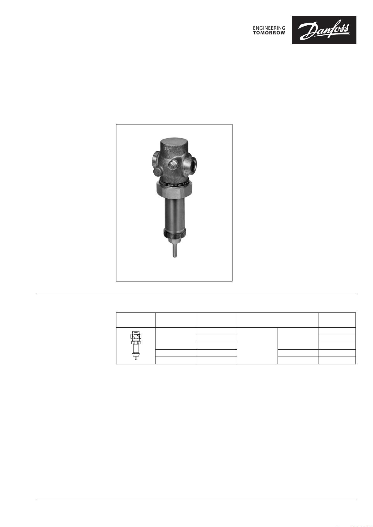
2 - way valve for steam, pressure relieved (PN 25)
VGS - external thread
Description
Ordering
Example:
Valve for steam, DN 15; kVS 1.6;
PN 25; T
- 1× VGS DN 15 valve
Option:
- 1× Weld-on tailpieces
The valve will be delivered together
with two adapters:
M34 × M45 and M34 × M30
200 °C; ext. thread
max
Code No: 065B0787
Code No: 003H6908
VGS is pressure relieved 2-way normally open (NO)
valves for steam, designed to be combined with:
- AVT Temperature actuators
- STM Safety temperature monitors
- STL Safety temperature limiters
- AMV(E) 20 / AMV(E) 30 electrical actuators
- AMV(E) 23 / AMV(E) 33 electrical actuators
with spring return function
In combination with AVT temperature actuators
and AMV(E) electrical actuators, valves can be
used for temperature control with steam or hot
water up to 200 °C.
Main data:
• DN 15-25
• kVS 1.0 - 6.3 m3/h
• PN 25
• Temperature:
- Steam/circ. water/glycolic water up to 30 %:
2 … 200 °C
• Connections:
- Ext. thread (weld-on, thread and flange
tailpieces)
• Flow and return mounting
Picture
1)
DN k
(mm) (m3/h)
15
20 4.5 G 1 A 065B0789
25 6.3 G 1¼ A 065B0790
VS
1.0
1.6 065B0787
3.2 065B0788
Cylindrical external
thread acc. to
Connection Code No.
G ¾ A
ISO 228/1
VGS valve
1)
Two adapters are deli vered together with the valve: M34 × M 45 and M34 × M30 (for detai ls see Accessories);
M34 × M45 is factory as sembled on the valve.
065B0786
© Danfoss | 2017.01
VD.HD.W3.02 | 1
Page 2
Data sheet 2 - way valve for steam, pressure relieved (PN 25)
Ordering (continuous)
Accessories
Picture Type designation DN Connection Code No.
15
Weld-on tailpieces
20 003H6909
-
25 00 3H6910
External thread tailpieces
15
Conical ex t. thread acc. to
20 R ¾ 003H6903
25 R 1 003H6904
EN 1022 6-1
R ½ 003H6902
15
Flange tailpieces
20 003H 6916
Flanges PN 25, acc. to EN 1092-2
25 0 03H6 917
1)
Adapter
2)
Adapter
1)
Adapter for VGS combi nations with electrical a ctuators type AMV(E) 20, 23, 3 0, 33.
2)
Adapter for VGS combina tions with temperature act uators AVT, temperature monito rs STM and temperature limi ters STL.
M34 × 1.5 mm / M30 × 1.5 mm 003H18 35
M34 × 1.5 mm / M45 × 1.5 mm 003H6927
Service kits
Picture Type designation for valves DN k
15 3.2
Valve body extension with stuf fing box
25 6.3
VS
003H6908
003H6915
Code No.
003H687720 4.5
Technical data
Nominal diameter DN 15 20 25
k
value m3/h 1.0 1.6 3. 2 4.5 6.3
VS
Stroke mm 3 5
Control ratio >1: 50
Control characteristic linear
Cavitation factor z ≥ 0.6 ≥ 0.55
Leakage acc. to standard IEC 534 % of k
VS
Nominal pressure PN 25
Max. differential pressure bar 10
Medium Steam / Circulation water / Glycolic water up to 30%
Medium pH Min. 7, max. 10
Medium temperature
Connections
valve External thread
tailpieces Weld-on, external thread and flange
°
C 2 … 200
Materials
Valve body Red bronze CuSn5ZnPb (Rg5)
Valve seat Stainless steel, mat. No. 1.4571
Valve cone Stainless steel, mat. No. 1.4122
Pressure relive system Bellows
≤ 0.05
2 | VD.HD.W3.02
© Danfoss | 2017.01
Page 3
Data sheet 2 - way valve for steam, pressure relieved (PN 25)
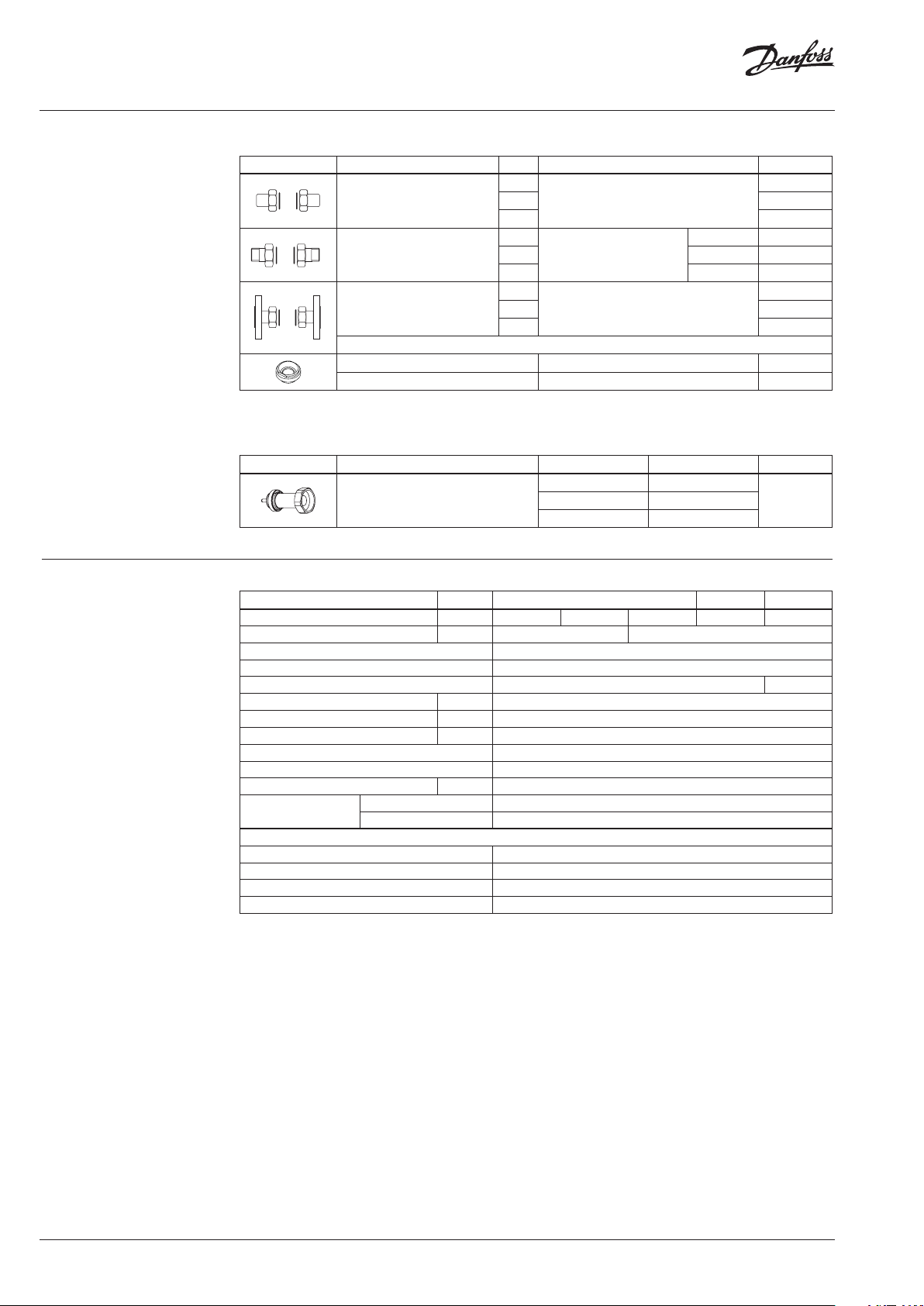
Application principles
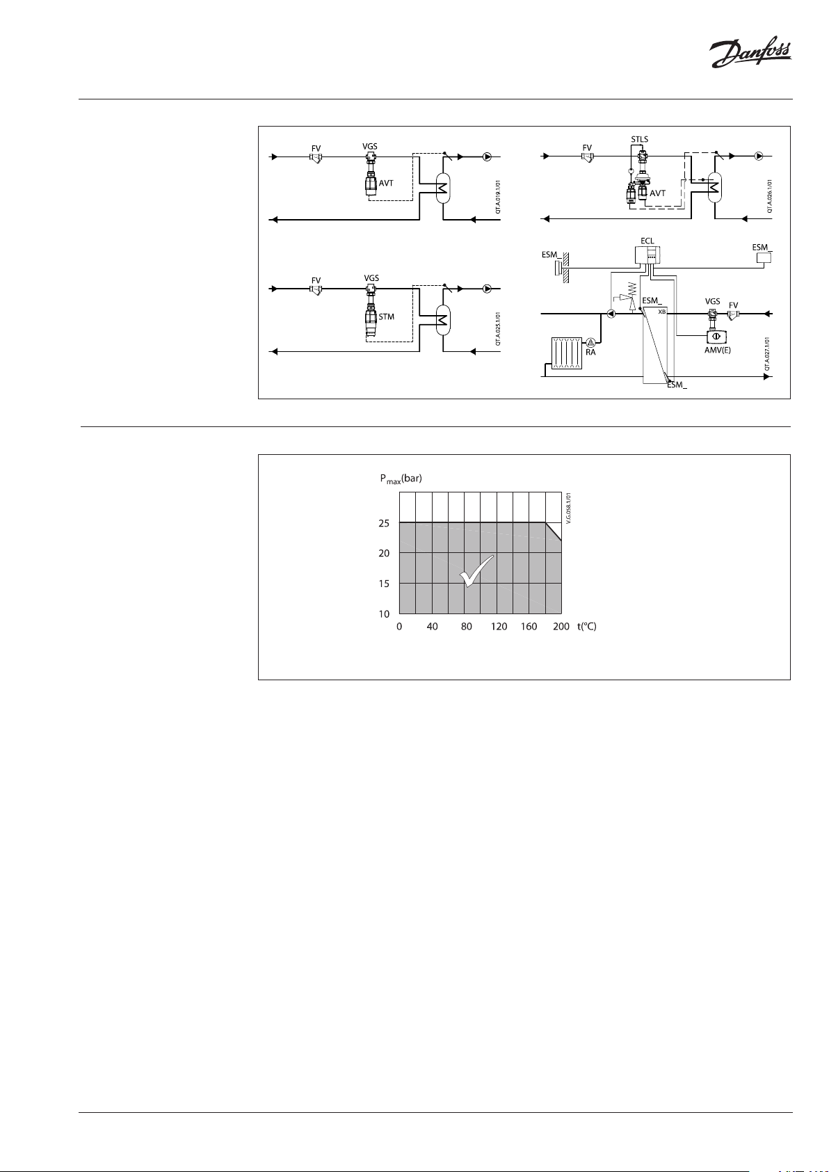
Pressure temperature
diagram
CuSn5ZnPb (Rg5) PN 25
Maximum allowed operating pressure as a function of medium temperature (according to EN 1092-3).
© Danfoss | 2017.01
VD.HD.W3.02 | 3
Page 4

Data sheet 2 - way valve for steam, pressure relieved (PN 25)
Installation position
Valves can be installed in any position.
Temperature controller and safety
temperature monitor
STM / VGS + AVT + adapter M34/M45
(003H6927)
Up to medium temperature of 160 °C
temperature controller AVT/VGS and safety
temperature monitor STM/VGS can be installed
in any position.
Electrical actuator
Note!
Installation positions for electrical actuators AMV(E) have
to be observed as well. Please see relevant Data sheet
For higher temperatures temperature controller
AVT/VGS and safety temperature monitor STM/VGS
have to be installed horizontal and in horizontal
pipes with the actuator oriented downwards.
Safety temperature limiter
STL + VGS + adapter M34/M45 (003H6927)
Up to medium temperature of 100 °C safety
temperature limiter VGS + STLS can be installed
in any position.
For higher temperatures safety temperature
limiter VGS + STL have to be installed in
horizontal pipes only, with a pressure actuator
oriented downwards.
4 | VD.HD.W3.02
© Danfoss | 2017.01
Page 5

Data sheet 2 - way valve for steam, pressure relieved (PN 25)
Sizing
© Danfoss | 2017.01
Steam valve sizing is based on 40 % drop of the
steam pressure across the valve when fully open.
At this condition the steam is travelling at or
close to its critical velocity (approx. 300 m/s) and
throttling would occur over the full valve stroke.
If the steam is travelling slower than this, then
the first part of the valve stroke would merely
increase the velocity of the steam without
reducing the volumetric flow.
VD.HD.W3.02 | 5
Page 6

Data sheet 2 - way valve for steam, pressure relieved (PN 25)
Sizing (continuous) 1. For saturated steam
Given data:
Flow rate: 70 kg/h
Absolute inlet pressure: 5 bar (500 kPa)
Remark:
For this example follow dashed line
The absolute inlet pressure is 500 kPa. Critical
pressure drop (40% of 500 kPa) is 200 kPa. Locate
the diagonal line corresponding to the pressure
drop of 200 kPa (line A-A).
Read the absolute inlet pressure on the lower left
hand scale (point B), and draw a horizontal line
across until it meets the pressure drop diagonal
A-A at point C.
From this point C extend a vertical line upwards
until it meets the horizontal line representing
the steam flow of 70 kg/h from point D. The
intersection of this is point E.
The nearest diagonal kVS line above this is line
F-F with a kVS of 1.6. If the ideal valve size is not
available the next largest size should be selected
to ensure design flow.
The pressure drop through valve at the flow rate
is found by the intersection of the 70 kg/h line
with F-F (point E’) and dropping a vertical line
downwards; this actually hits the horizontal line
for 500 kPa absolute inlet pressure (point E’’)
at a pressure drop diagonal of 90 kPa. This is
only 18 % of the pressure drop accross the valve
and the control quality will not be good until
the valve has partially closed. As with all steam
valves this compromise is necessary since the
next smaller valve would not pass the required
flow (maximum flow would be about 60 kg/h;
point P).
The maximum flow for the same inlet pressure
is found by extending the vertical line (C-E)
through point E until it crosses the kVS 1.6 line F-F
(point G) and reading off the flow (90 kg/h).
2. For superheated steam
Given data:
Flow rate: 170 kg/h
Absolute inlet pressure: 5 bar (500 kPa)
Steam temperature: 190 °C
Remark:
For this examp le follow dotted line
The procedu re for superheated steam is mu ch the same as for
saturated steam , but uses a different fl ow scale which slightly
elevates the rea dings according to the degree of su perheat.
As before, the diagonal critical pressure drop
line A-A is located at 40 % of 500 kPa (200 kPa).
The horizontal inlet pressure line through
point B is now extended to the left to read off
the corresponding saturated steam temperature
at point H (150 °C). The difference between
the saturated steam temperature and the
superheated steam temperature is
190 °C − 150 °C = 40 °C (see point J).
The superheated steam flow 170 kg/h is found
on the upper right hand scale (point K). From
here the diagonal line is followed down until it
meets a vertical line from the steam temperature
elevation (40 °C, point J) at point L.
As before, the horizontal line through point B
is drawn to cut line A-A at point C. The point
where the vertical line from point C meets the
horizontal line from point L is the operating
point (point M). This horizontal line, L-M, is the
corrected flow line. The nearest diagonal line
above this is line N-N with a kVS 3.2. A vertical
line dropped from the intersection of L-M line
with line N-N (point M’) intersects the 500 kPa
absolute inlet pressure line (point M’’) at a
pressure drop diagonal of about 150 kPa.
This is about 30% of the pressure drop accross
the valve which will give reasonable control
quality (compared to recommended ratio of
40 %).
6 | VD.HD.W3.02
© Danfoss | 2017.01
Page 7

Data sheet 2 - way valve for steam, pressure relieved (PN 25)
Design
1. Valve body
2. Valve insert
3. Pressure relieved valve cone
4. Valve stem
5. Valve body extension
6. Stuffing box
Dimensions
L
DN 15 20 25
L
VGS
H 156 .5 155 158 .5
65 70 75
mm
Weight kg 0.7 0.8 0.9
M34
H
M30
Adapter
M34 × 1.5 mm / M30 × 1.5 mm
L
3
d
R
SW
1)
DN R
L
2
SW
SW d L
2)
1
mm
M34 × 1.5 mm / M45 × 1.5 mm
L
1
L2L
3
SW
k d
M34
M45
Adapter
n
2
45°
n
d
2
k
15 ⁄ 32 (G ⁄A) 21 13 0 120 139 65 14 4
20 ⁄ 41 (G 1A ) 26 150 131 154 75 14 4
25 1 50 (G 1⁄A) 33 160 145 159 85 14 4
1)
Conical ex t. thread acc. to EN 10226-1
2)
Flanges PN 25, acc. to EN 1092-2
© Danfoss | 2017.01
VD.HD.W3.02 | 7
Page 8

Danf
already on order pro
All trademarks in this material are property of the respec
Data sheet 2 - way valve for steam, pressure relieved (PN 25)
oss can accept no responsibility for possible errors in catalogues, brochures and other printed material. Danfoss reserves the right to alter its products without notice. This also applies to products
vided that such alterations can be made without subsequential changes being necessary eady agreed.
8 | VD.HD.W3.02
tive companies. Danfoss and the Danfoss logotype are trademarks of Danfoss A/S. All rights reserved.
© Danfoss | DHS-SRMT/SI | 2017.01
 Loading...