

Page 1
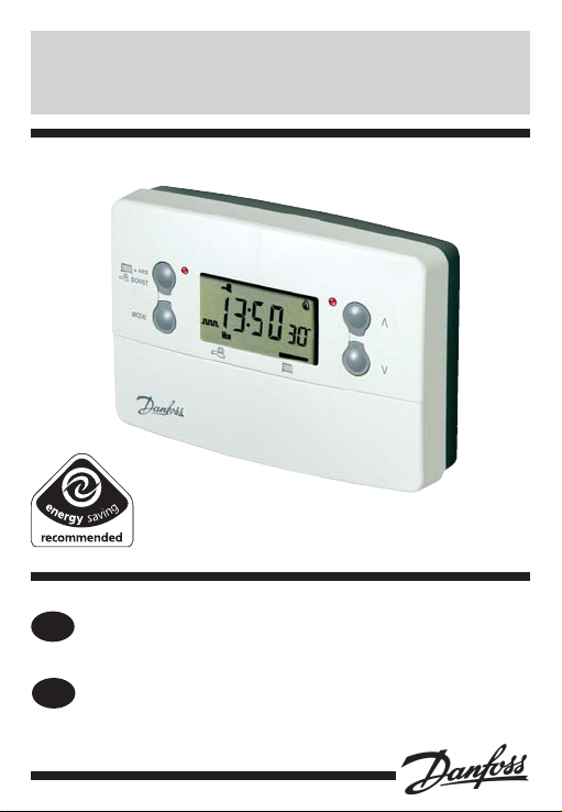
TP9000
®
Certification Mark
Installation Instructions
GB
User Instructions
Instrukcja montażowa
PL
Instrukcja obsługi
Electronic Programmable
Room Thermostat plus
Domestic Hot Water Timer
Page 2

Index
Installation Instructions 3-14
Product Specifi cation 3
Installation 4
Cable Access and Wiring 5
Installer Advanced Programming Options 8
User Instructions 15-31
What is a Programmable Room Thermostat 15
Preset programmes 17
Setting Date and Time 18
Changing Preset Programmes 20
User overrides 27
User Advanced Programming Options 33
Overview of Installer Selectable Features 37
Setting References 39
2
TP9000
Page 3

Installation Instructions
Please note: This product should only be installed by a qualifi ed
electrician or competent Heating installer, and should be in
accordance with the current edition of the IEEE wiring regulations.
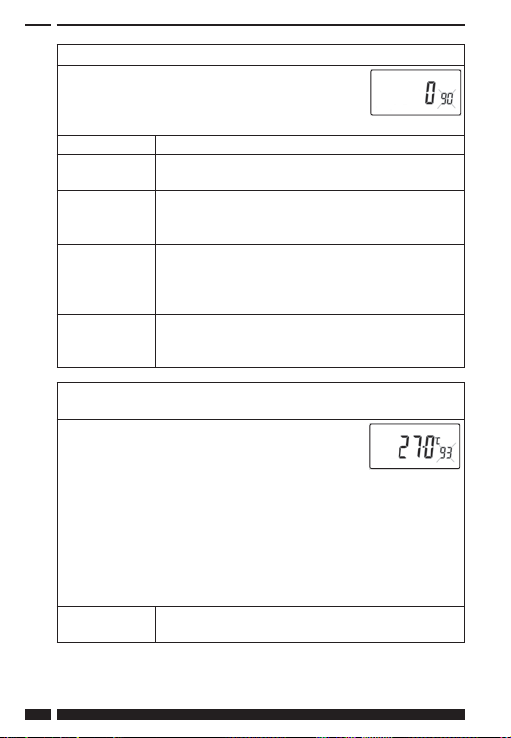
Product specifi cation
Specifi cation 230V model 24V model
Power supply 230 Vac, ±15%,
Switching action
Unit switch rating 230 Vac, 3(1)A 24Vac, 3(1)A
Memory Backup Retained for life of product
Heat Temperature Range
Setting
Factory Set Calendar Clock Automatic Summer/Winter time
Remote Sensor Inputs
(‘A’ models only)
Programme resolution ± 1 minute
Timing Accuracy ± 1 minute
Dimensions, mm (W, H, D) 135 x 88 x 32
Design standard EN 60730-2-7 +EN60730-2-9
Control Pollution Situation Degree 2
Rated Impulse Voltage 2.5 kV
Ball Pressure Test 75°C
50/60 Hz
2 x SPDT internally linked, Type 1BS
Can be set by installer for remote
sensor, limited sensor, window con-
tact, tele-switch or outdoor sensor
24 Vac, ±15%,
50/60 Hz
5°C - 30°C
change
GB
PL
DANFOSS HEATING 3
Page 4

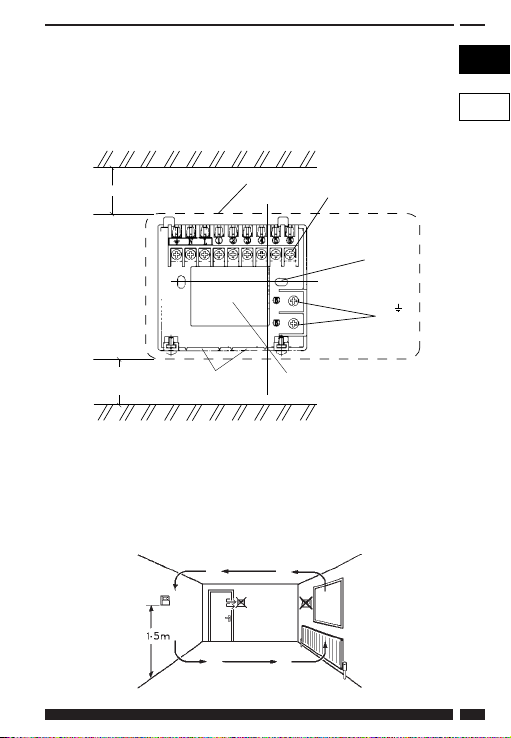
Installation
• Remove wallplate from unit by unscrewing the two screws on the
bottom edge of the unit.
• From the top left hand corner of the wallplate, there must be
clearances of at least 140 mm to the right, 15mm to the left, 30mm
above and 100mm below in order to mount the plug-on module.
• The wallplate must be securely mounted either directly to the
wall using suitable wood screws or to a fl ush mounted 1-gang
electrical accessory box using M3.5 screws.
• Cable access can either be from behind for concealed cabling, or
from below for surface cabling. If surface cable is used, cut out
cable access slot on plug-on module prior to mounting.
• For wiring connections refer to diagram on page 6.
The TP9000 is double insulated and does not require an earth
connection, however a parking terminal is provided on the
wallplate. This is clearly marked with an Earth symbol.
• Prior to mounting the plug-on module, DIL switches on the rear of
the plug-on module must be set. See diagram below for available
options.
• Mount plug-on module to wallplate by locating tabs on top of
wallplate in apertures on rear of module, hinge down and press
fi rmly to wallplate before tightening securing screws on bottom
of wallplate.
Prior to mounting the unit the 2 DIL switches on the rear of the
unit have to be moved to the required position. The factory
presets are shown below.
Sw. No.
Keyboard disabled
1
2
4
OFF
Reset disabled Reset enabled
ON
Keyboard enabled
TP9000
Page 5
IMPORTANT: The supply to this unit should by wired via a double pole
isolation switch in accordance with BS EN60730-1, i.e. one which provides
air gaps of at least 3mm in both poles of the mains, and incorporates a 3
!
amp fuse. It is strongly recommended that solid conductors be used.
GB
PL
30mm minimum
Clearance for
screwdriver
access
Outline of unit
Surface fixed cable
bottom entry knockouts
C/L
Terminal block
Rear entry
cable access
Wall or
Plaster box
fitting
N &
looping
terminals
Thermostat and Remote Room Sensor:
Fix at a height of approximately 1.5m from the fl oor, away from
draughts or heat sources such as radiators, open fi res or direct
sunlight.
DANFOSS HEATING 5
Page 6
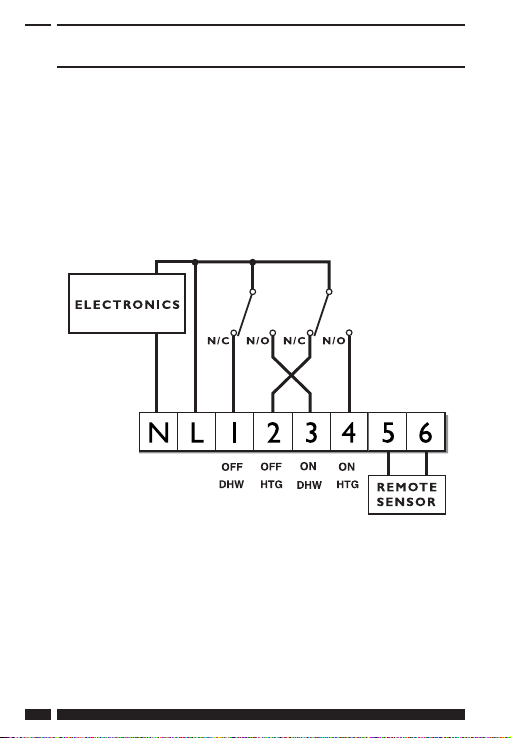
Wiring
NOTE:
The TP9000 does not have voltage free contacts, therefore it is NOT
suitable for connection to extra low voltage equipment (i.e. > 50
Volts).
Remote Sensor to be wired with 1mm 2 core double insulated cable
only. Cable length should not exceed 50 metres. Sensor cable should
NOT be run parallel to mains cable.
Remote sensor inputs
The TP9000 incorporates an input which can be used to connect one
of the following:
1) remote room temperature sensor
2) limit sensor, for example, fl oor temperature sensor (sold as
accessory).
3) window contacts, card reader contacts, outdoor sensor (sold as
accessory) or teleswitch contacts.
See Installer Advanced Programming Options for set-up instructions.
6
TP9000
Page 7
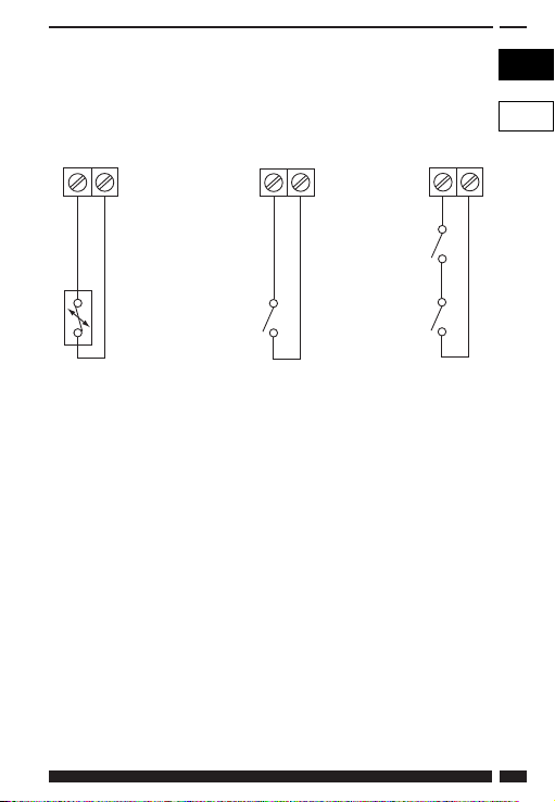
Remote sensor inputs
Terminals 5 and 6 are the designated remote sensor inputs. These can
be found on the top right hand side of the wallplate.
GB
PL
5
6
Window or
teleswitch
contact
(NO or NC)
Confi gured for
remote room,
limit or outdoor
sensor
DANFOSS HEATING 7
5
6
Confi gured for
window contact or
other contact such
as teleswitch
Window
contact (NC)
Teleswitch
contact (NC)
5
6
Confi gured for
window contact
and other contact
such as teleswitch
Page 8

Installer advanced
programming options
TP9000 incorpor ates a number of advanced features which can be set
by the user. These are accessed via a User Advanced Programming
Mode, please refer to User Advanced Programming in the user
instructions for details (see page 33)
Installer advanced programming options
TP9000 incorporates an additional number of advanced features which
can be set by the installer to improve the operating effi ciency of the
system and where required, to change the user functionality of the
product. These are accessed via an Installer Advanced Programming
Mode. These settings are optional and need only be made if there is a
demand for the enhanced functions.
Service Interval Timer
Instructions on how to access this feature are available from our
customer support desk. Please note these are only issued to boni-fi de
Heating installers.
Entering Installer Advanced Programming Mode
To access the Installer Advanced Programming Mode follow the steps
below:
a) Press and hold
enter User Advanced Programming, the display
will change to fi gure opposite.
b) Press and hold
to enter Installer Advanced Programming, the
display will change to fi gure opposite.
V and PROG for 3 seconds to
V, Λ and PROG for 5 seconds
8
TP9000
Page 9
c) Use + and - keys to scroll backwards and forwards between options
then
V and Λ keys to change the option settings. The fl ashing digit
on the right hand of the display indicates the number of the selected
option. The large characters display the option value selected.
d) To return to RUN, press and hold PROG until the display returns to
RUN mde.
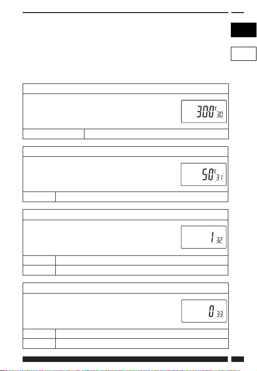
Option 30 - Set upper limit of temperature range
This allows the upper limit of the thermostat setting
range to be electronically limited. Press + until
Option 30 is displayed, use V and Λ to select required
setting.
Setting 40 - 5°C (factory setting is 30°C)
Option 31 - Set lower limit of temperature range
This allows the lower limit of the thermostat setting
range to be electronically limited. Press + until
Option 31 is displayed, use V and Λ to select required
setting.
Setting 5 - 40°C (factory setting is 5°C)
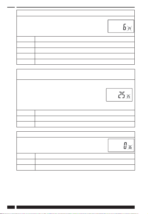
Option 32 - Enable Off at lower limit
This enables an OFF function to be selected if a set
point below the lower limit is selected. Press + until
Option 32 is displayed, use
setting.
Setting 0 Disabled
Setting 1 Enabled (factory setting)
Option 33 - Enable On at upper limit
This enables an ON function to be selected if a set
point above the upper limit is selected. Press + until
Option 33 is displayed, use
setting.
Setting 0 Disabled (factory setting)
Setting 1 Enabled
DANFOSS HEATING 9
V and Λ to select required
V and Λ to select required
GB
PL
Page 10
Option 34 - Select On/Off or Chrono-proportional
This allows the thermostat to be set to run in On/Off
mode or for a chrono-proportional cycle rate to be
selected. Press + until Option 34 is displayed, use V
and Λ to select required setting.
0 On/Off
3 3 cycles per hour
6 6 cycles per hour (factory setting)
9 9 cycles per hour
12 12 cycles per hour
Option 35 - Set integration time (Option 34 set to 3, 6, 9 or 12)
(seek advice prior to adjusting)
This adjusts the integration time of the PI algorithm
to increase control accuracy. It is only active if
option 34 has been set to Chrono 3, 6, 9 or 12.
It should only be adjusted after seeking advice
from the manufacturer. Press + until Option 35 is
displayed, use
V and Λ to select required setting.
2.5 Integration time set to 2.5% (factory setting)
5 Integration time set to 5%
10 Integration time set to 10%
Option 36 - Set temperature override rule
This establishes the degree of temperature override
available to the user. Press + until Option 36 is
displayed, use
V and Λ to select required setting.
Setting 0 No limit (factory setting)
Setting 1 Limited to ±2°C
Setting 2 No override allowed
10
TP9000
Page 11
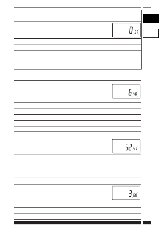
Option 37 - Set time duration of override rule
(Option 36 set to 1 or 2)
This establishes the duration of a temperature
override available to the user. Press + until Option 37
is displayed, use V and Λ to select required setting.
Setting 0 Next event (factory setting)
Setting 1 1 hour
Setting 2 2 hours
Setting 3 3 hours
Setting 4 4 hours
Option 40 - Number of Events per Day (Heating)
This sets the thermostat to operate with either 2, 4 or
6 switching events per day or to run it in stat mode.
Press + until option 40 is displayed, use Λ or V to
select required setting.
1 Stat mode
2 Two switching events per day
4 Four switching events per day
6 Six switching events per day (factory setting)
Option 41 - Operating Mode (Heating) (option 40 set to 2, 4, or 6)
This sets the thermostat to operate using either
5/2 day or 24 hour mode. Press + until option 41 is
displayed, use Λ or V to select required setting.
7 7 Day programming (factory setting)
5-2 or A-B 5-2 Day programming or A-B programming
24 24 hour programming
Option 60 - Number of events per day (Hot Water)
This sets the number of Hot Water on/off switching
times per day. Press + until option 60 is displayed, use
Λ or V to select required setting.
Setting 1 1 on/off event per day
Setting 2 2 on/off events per day
Setting 3 3 on/off events per day (factory setting)
DANFOSS HEATING 11
GB
PL
Page 12
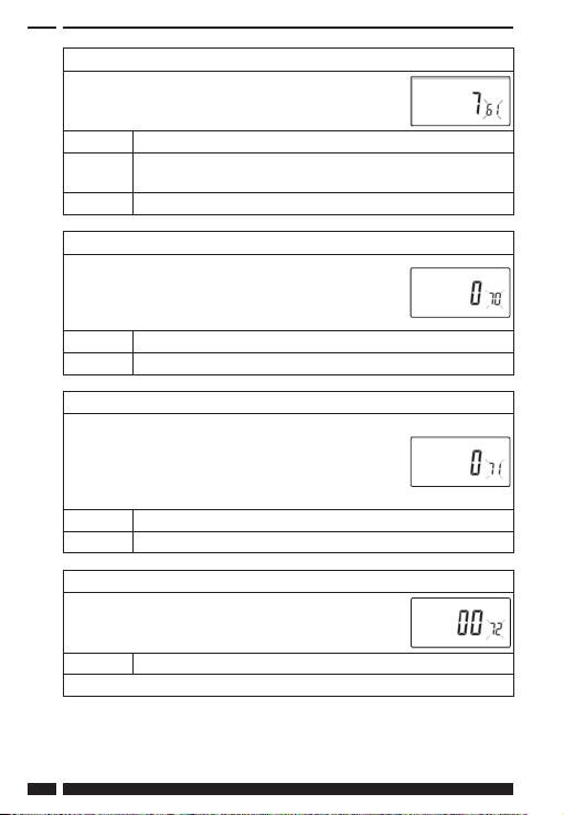
Option 61 - Hot Water Event - Days per week
This sets the schedule of Hot Water on/off switching
times per week. Press + until Option 61 is displayed,
use V and Λ to select required setting.
24 24 Hour
5-2 Either 5+2 day or A+B days depending on user APM
setting
7 7 Day (factory setting)
Option 70 - Keyboard disable rules
This establishes the degree of functionality of the
keyboard available to the user. It is only active if DIL
switch 1 is set to “Disabled”. Press + until Option 70 is
displayed, use V and Λ to select required setting.
Setting 0 Normal lock: Programming functions locked (factory setting)
Setting 1 Full lock: All keys are disabled
Option 71 - Random start rules (24V/230 Volt models only)
This enables a random start on power-up following a
power cut to reduce load on the electrical network.
Random delay is in the range of 2 - 90 seconds. Press
+ until Option 71 is displayed, use V and Λ to select
required setting.
Setting 0 Disabled (factory setting)
Setting 1 Enabled
Option 72 - Owner site reference number
This enables multi-site owners to store a site reference
number in the thermostat. Press + until Option 72 is
displayed, use V and Λ to select required setting.
Setting Any value between 00 and 99 can be set
Factory setting is 00
12
TP9000
Page 13
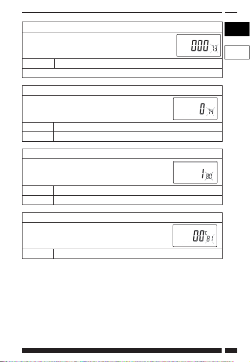
Option 73 - Owner thermostat reference number
This enables site owners to store a thermostat reference
number in the thermostat. Press + until Option 73 is
displayed, use V and Λ to select required setting.
Setting Any value between 000 and 999 can be set
Factory setting is 000
Option 74 - Date format for calendar clock
This allows date format to be chosen. Press +
until Option 74 is displayed, use V and Λ to select
required setting.
Setting 0 European format (dd/mm/yy), (Factory setting)
Setting 1 North American format (mm/dd/yy)
Option 80 - Enable/Disable + Hrs Boost
Enables or disables the +Hrs button. use V and Λ
to select required setting. Press + until Option 80 is
displayed, use V and Λ to select required setting.
Setting 0 +Hrs Boost button disabled
Setting 1 +Hrs Boost button enabled (factory setting)
Option 81 - Thermostat calibration bias
This allows the thermostat calibration to be biased
by up to ±1.5°C. Press + until Option 81 is displayed,
use V and Λ to select required setting.
Setting Any value between ±1.5 in 0.5°C steps (Factory setting is 0°C)
GB
PL
DANFOSS HEATING 13
Page 14
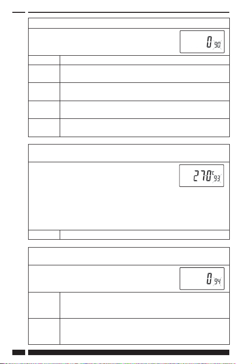
Option 90 - Defi ne remote sensor type
This allows type of remote sensor input type to be
defi ned. Press + until Option 90 is displayed, use V
and Λ to select required setting.
Setting 0 No remote sensor fi tted
Setting 1 Remote room or duct sensor fi tted, internal sensor disabled
(factory setting)
Setting 2 Remote limit sensor fi tted, refer to option 93 to defi ne set-
point
Setting 3 Confi gured as digital input for window, card reader or
teleswitch, refer to option 94 to defi ne o/c or s/c.
Setting 4 Outdoor sensor fi tted internal sensor active, outdoor
sensor used for display purposes only
Option 93 - Set limit sensor set-point
(option 90 set to 2)
This allows the thermostat limit sensor to be set,
typical application is fl oor Heating. Press + until
Option 93 is displayed, use V and Λ to select
required setting. If the temperature sensed by
the limit sensor exceeds the limit setting the
output will be turned off until the temperature
has dropped by 2°C. “F10” will fl ash in the display
while the output is disabled.
Setting Any value between 20 - 50°C (Factory setting is 27°C)
Option 94 - Confi gure digital input switch type, “A” models only,
(option 90 set to 3)
This allows switch type of digital input to be
confi gured. Press + until Option 94 is displayed,
use V and Λ to select required setting.
Setting 0 Contacts NC, open circuit contact to force unit into
thermostat mode, short circuit contacts to return to normal
operation
Setting 1 Contacts NO, short circuit contacts to force unit into
thermostat mode, open circuit contacts to return to normal
operation (Factory setting)
14
TP9000
Page 15

What is a programmable room thermostat?
... an explanation for householders
A programmable room thermostat is both a programmer and a room thermostat. A
programmer allows you to set ‘On’ and ‘Off ’ time periods to suit your own lifestyle. A
room thermostat works by sensing the air temperature, switching on the heating when
the air temperature falls below the thermostat setting, and switching it off once this set
temperature has been reached.
So, a programmable room thermostat lets you choose what times you want the heating
to be on, and what temperature it should reach while it is on. It will allow you to select
diff erent temperatures in your home at diff erent times of the day (and days of the week)
to meet your particular needs.
Turning a programmable room thermostat to a higher setting will not make the room
heat up any faster. How quickly the room heats up depends on the design of the heating
system, for example, the size of boiler and radiators.
Neither does the setting aff ect how quickly the room cools down. Turning a
programmable room thermostat to a lower setting will result in the room being
controlled at a lower temperature, and saves energy.
The way to set and use your programmable room thermostat is to fi nd the lowest
temperature settings that you are comfortable with at the diff erent times you have
chosen, and then leave it alone to do its job. The best way to do this is to set low
temperatures fi rst, say 18°C, and then turn them up by one degree each day until you are
comfortable with the temperatures. You won’t have to adjust the thermostat further. Any
adjustments above these settings will waste energy and cost you more money.
If your heating system is a boiler with radiators, there will usually be only one
programmable room thermostat to control the whole house. But you can have diff erent
temperatures in individual rooms by installing thermostatic radiator valves (TRVs) on
individual radiators. If you don’t have TRVs, you should choose a temperature that is
reasonable for the whole house. If you do have TRVs, you can choose a slightly higher
setting to make sure that even the coldest room is comfortable, then prevent any
overheating in other rooms by adjusting the TRVs.
The time on the programmer must be correct. Some types have to be adjusted in spring
and autumn at the changes between Greenwich Mean Time and British Summer Time.
You may be able to temporarily adjust the heating programme, for example, ‘Override’,
‘Advance’ or ‘Boost’. These are explained in the manufacturer’s instructions.
Programmable room thermostats need a free fl ow of air to sense the temperature, so
they must not be covered by curtains or blocked by furniture. Nearby electric fi res,
televisions, wall or table lamps may prevent the thermostat from working properly.
DANFOSS HEATING 15
GB
PL
Page 16

User Instructions
An introduction to your
programmable room thermostat
The TP9000 is a programmable thermostat designed to control both
your Hot Water and Heating.
Depending on the setting value in the Installer Advanced Programming
(option 41) you can have 7-day, 5-2 day or 24 hour programming. A full
explanation of these diff erent methods is located on page 20.
The thermostat can also be set by you to provide two diff erent
programming blocks which can then be assigned to any day of the
week, this is referred to as A/B programme operation.
The Heating side of the TP9000 can be set by your installer to provide
up to 2, 4 or 6 time and temperature settings each day, whereas the Hot
Water can be set to provide 1, 2 or 3 on/off periods each day.
The thermostat also features useful overrides, including a
programmable frost setting.
The TP9000 has some advanced features which the installer will setup if they are required. There are also a number of advanced features
which can be set up by you. These advanced settings alter the way that
your thermostat operates, some also aff ect the programming functions
and the user overrides. Please read the User Advanced Programming
instructions before programming the unit (see page 33).
16
TP9000
Page 17
General Operation
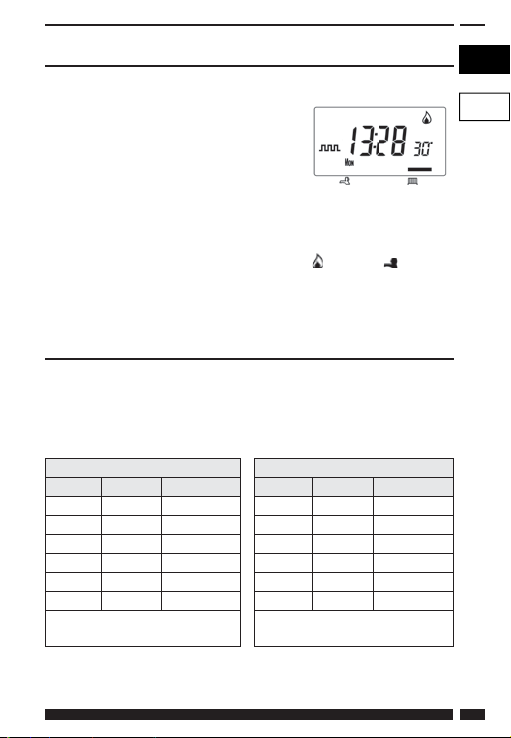
The TP9000 has two distinct display modes - one for Hot Water, one
for Central Heating. The currently selected
mode is indicated by a bar at the bottom
of the LCD screen when in run mode. The
right bar is for Heating, the left bar is for Hot
Water.
When programming the TP9000 it is
important to be aware of which mode is active before beginning
programming. To toggle between modes, press the CH/HW button.
The display will change and the indicator bar at the bottom will move
to refl ect which mode is selected. The fl ame (
are used in conjunction with the LED’s to show the current output
status (on/off ). The output status is always shown for both Heating and
Hot Water regardless of the display mode.
) and tap ( ) symbols
Preset programmes
Your TP9000 comes ready programmed with a set of operating times and
temperatures which suit most people. Please remember that some of the
options available will depend on how the installer has set up the unit.
Central Heating
Weekdays (Mon-Fri) Weekend (Sat-Sun)
Event Time Temp. °C Event Time Temp. °C
1 06:30 20 1 07:30 20
2 08:30 15 2 09:30 20
3 11:30 20 3 11:30 20
4 13:30 15 4 13:30 20
5 16:30 21 5 16:30 21
6 22:30 15 6 22:30 15
Note: these are also times for
Block “A” programmes
Note: If set up for 4 events per day, events 3 & 4 are skipped. If set up
for 2 events per day, events 2, 3, 4 & 5 are skipped. In both cases the
events are re-numbered.
DANFOSS HEATING 17
Note: these are also times for
Block “B” programmes
GB
PL
Page 18

Hot Water
Weekdays (Mon-Fri) Weekend (Sat-Sun)
Event Time Temp. °C Event Time Temp. °C
1 06:30 On 1 07:30 On
2 08:30 Off 2 09:30 Off
3 11:30 On 3 11:30 On
4 13:30 Off 4 13:30 Off
5 16:30 On 5 16:30 On
6 22:30 Off 6 22:30 Off
Note: these are also times for
Block “A” programmes
Note: If set up for two on/off events per day, events 3 and 4 are skipped.
If set up for one on/off event per day, events 2, 3, 4 & 5 are skipped. In
both cases the events are re-numbered.
Note: these are also times for
Block “B” programmes
Customising the display
For the sake of clarity, the instructions assume that the display setting
uses a 24 hour clock, °C and that days of the week are shown as text.
All of these settings can be personalised after the thermostat has been
programmed, see page 27
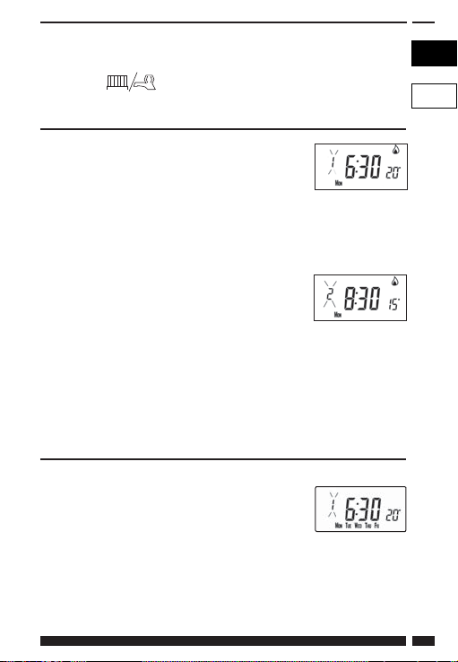
Setting the correct date and time
Your TP9000 incorporates a real time clock with calendar function that
automatically changes time in both Spring and Autumn. The time and
date is set in the factory for the UK time zone, and does not normally
require adjustment. If you live in another time zone refer to “Time zone
off set” on page 34. However, should it be found necessary to adjust
time or date for any other reason refer to the following instructions.
18
TP9000
Page 19
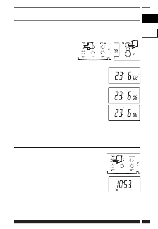
Setting the date
Press and hold Λ and PROG for 3 seconds, to display date in dd/mm/yy
format.
The YEAR number will fl ash, use Λ or V to correct
the year.
Use - or + to move to MONTH, then use Λ or V to
correct month.
Use - or + to move to DATE in month, then use Λ or
V to correct day in month.
If you attempt to select an invalid date the
unit software will reject it and apply the nearest valid date. It is
recommended that date is set in the order, yy/mm/dd.
Setting the correct time
After setting the date press PROG to display the
time. The time display will fl ash on and off .
Use the + and - buttons to set the correct
time (press and hold to change in 10 min.
increments).
GB
PL
DANFOSS HEATING 19
Page 20

Setting the correct day
The day of the week is set automatically. Press
PROG to return to normal operation (RUN).
Accepting the preset programmes
If you are happy with the preset times shown in the table on page 17
you need take no further action.
Changing the preset programmes
Before you change the preset programmes
Your installer will have set the unit to operate in one of the following
modes:
7 day - each day has independent times and temperatures off ering
full fl exibility of programming (page 21).
5/2 day - one set of programmes for weekdays and another for
weekends (page 21).
24 hr - one set of programmes for the whole of the week (page 22).
Alternatively
A/B - The unit can also be set by you to provide two programme
blocks, either of which can be applied to diff erent days of the week.
If this is required refer to page 23 for instructions on how to turn on
this feature.
Please Note
The unit must be programmed in sequence, event times cannot be
set out of sequence.
If you want to leave a preset time as it is, simply press NEXT to move
to the next setting.
If you want to return the unit to RUN, press PROG and hold until the
display returns to the previous RUN mode. Alternatively leave alone
and the unit will automatically return to RUN after 2 minutes.
Your installer will have set your unit to programme 6, 4 or 2 events
per day for Heating, or 1, 2 or 3 events per day for Hot Water. This
will determine the number of events per day that you are able to
programme.
20
TP9000
Page 21
Before beginning programming the unit remember to check that the
correct function is selected i.e. Heating or Hot Water by using the CH/
HW button.
Changing the preset programmes in 7 day mode
a) Press PROG once until the display shows the
fi rst preset time and temperature
b) Use the + and - buttons to adjust the time
(press and hold to adjust in 10 minute increments)
c) Use the Λ and V buttons to adjust the required temperature (CH
only)
d) Press NEXT to move to the next preset time
and/or temperature (Event 2)
e) Once all events for the day have been
programmed, press DAY/HOL to move to the next day
f) Repeat steps b, c, d & e to programme the remaining weeks
events.
g) Press and hold PROG to return to the main screen.
Changing the preset programmes in 5/2 day mode
For Weekdays
a) Press PROG until the fi rst preset time and
temperature (Event 1 Days MON, TUE, WED,
THU, FRI)
b) Use the + and - buttons to adjust the TIME (press and hold to
change in 10 minute increments).
c) Use the Λ and V buttons to adjust the required TEMPERATURE (CH
only).
DANFOSS HEATING 21
GB
PL
Page 22
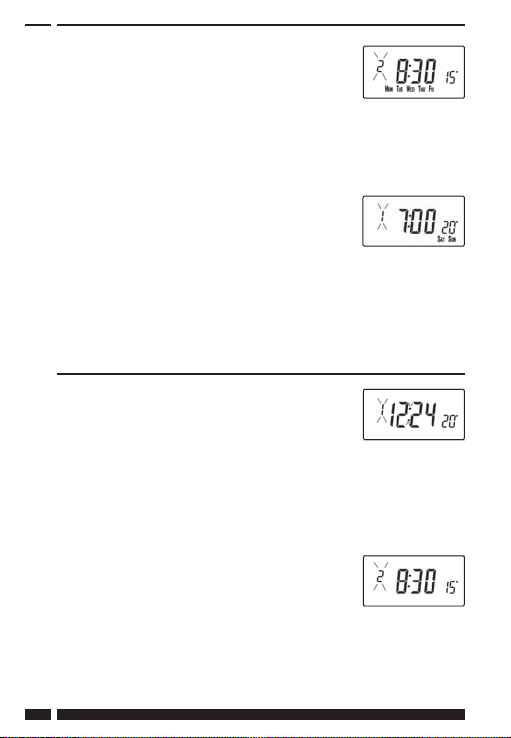
d) Press NEXT to move to the next preset time
and/or temperature (Event 2).
e) Repeat steps b, c, & d to programme the
remaining weekday events.
f) Press DAY/HOL to move on to weekend events.
For Weekends
Press PROG until the fi rst preset time and
temperature (Event 1 Days SAT, SUN) appears in
display.
Repeat steps b, c, & d above to programme the remaining weekend
events.
Press PROG to return to the main screen.
Changing the preset programmes in 24 hour mode
a) Press PROG until the fi rst preset time and
temperature (Event 1 for all days of the week)
appears in display.
b) Use the + and - buttons to adjust the TIME (press and hold to
change in 10 min increments).
c) Use the Λ and V buttons to adjust the required TEMPERATURE
(CH only).
d) Press NEXT to move to the next preset time
and/or temperature (Event 2).
e) Repeat steps b, c, & d to programme the
remaining events.
f) Press DAY/HOL to move on to weekend events.
22
TP9000
Page 23
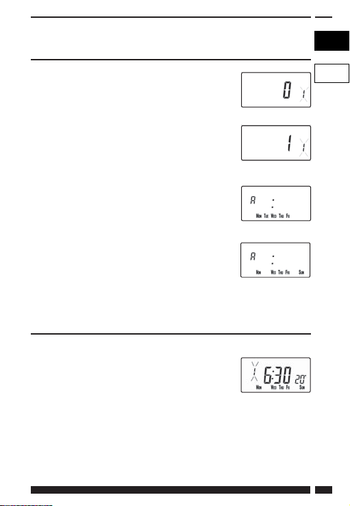
Changing preset programmes for AB programming
(Installer option 41 must be set to 5-2 day mode)
Press and hold PROG and V for 3 seconds. The
display will change to the fi gure opposite. This
will take you into User Advanced Programming
option 1.
Use Λ and V keys to enable or disable the function
(1=enabled, 0=disabled).
Press PROG for 5 seconds until the display returns
to previous RUN mode.
Press PROG once, the display will change to show
the default days assigned to programme “A” (days
MON, TUE, WED, THU, FRI).
Use the + and - keys to scroll forwards or backwards
through the days of the week.
To deselect a day press V, (for example TUE). To
select a day press Λ (for example SUN).
Any deselected days are automatically assigned to programme “B”.
Programming “A” programme days and events
a) Press PROG until the fi rst preset time and/or temperature (Event 1
for Programme A) appears in display.
b) Use the + and - buttons to adjust the TIME
(press and hold to change in 10 minute
increments).
c) Use the Λ and V buttons to adjust the required TEMPERATURE.
d) Press NEXT to move to the next preset time and temperature (CH
only) (Event 2).
e) Repeat steps b, c, & d to programme the remaining events.
DANFOSS HEATING 23
GB
PL
Page 24

Programming “B” programme days and events
a) Press DAY/HOL until the fi rst preset time
and temperature (Event 1 for Programme B)
appears in the display.
b) Use the + and - buttons to adjust the TIME (press and hold to
change in 10 minute increments).
c) Use the Λ and V buttons to adjust the required TEMPERATURE
(CH only).
d) Press NEXT to move to the next preset time and/or temperature
(Event 2).
e) Repeat steps b, c, & d to programme the remaining events.
Running the programme
Press PROG to return to previous RUN mode.
The Heating will now follow the times and
temperatures programmed.
Copy functions explained
There are 2 possible copy functions available. These are; Standard
Copy and Enhanced Copy. Copy functions are enabled/disabled in the
Advanced Programming Options (page 33)
Standard Copy: Pressing copy will copy the previous days events into
the displayed day. The unit will then display the 1st event for the new
day. This copy function is present only if the unit is set to run in 5+2 or
7 day mode.
24
TP9000
Page 25
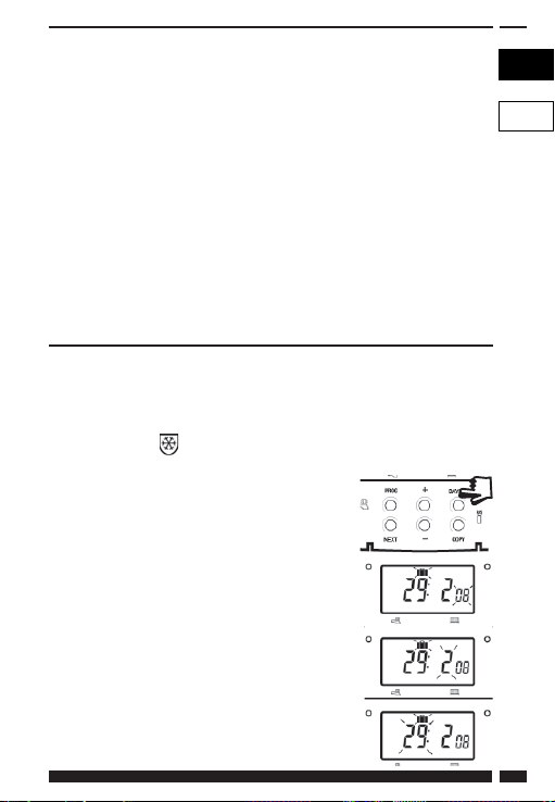
Enhanced copy: The enhanced copy function is available in 7 day
mode only. This allows any day to be copied to any other day, or days.
To use the enhanced copy function, go into the event programming
using the PROG button, then:
1) use the DAY button to fi nd the day to be copied from
2) press the COPY button to select the day to be copied from.
When selected, the day should begin to fl ash.
3) use the DAY button to fi nd the day to be copied to
4) press COPY button to copy the selected day
5) repeat steps 3 and 4 to select and copy other days
6) to stop copying, use the DAY button to go back to the
fl ashing day and press the COPY button. The previously
fl ashing day will stop fl ashing to indicate it has been deselected.
Holiday programme
The TP9000 is equipped with a holiday mode that enables it to
automatically bring back on the Heating and Hot Water when returning
from holiday. During the period when the unit is in holiday mode,
the Hot Water is turned off , and the central Heating is placed in frost
protection mode
To set up the holiday programme, please follow
the below steps:
a) Press and hold DAY/HOL
b) Use the Λ and V buttons to set the year
c) Use the + button to move to the month.
Use the Λ and V buttons to set the month
d) Use the + button to move to the day. Use
the Λ and V buttons to set the day
DANFOSS HEATING 25
GB
PL
Page 26

e) To exit and activate the holiday mode press
DAY/HOL once. The display will change,
Heating and Hot Water will be switched
off . The unit will stay in this state until the
programmed return date, at which point it
will resume normal operation.
f) Once in holiday mode, the return modes for both the heating
and hot water can be set. Use the CH/HW button to change
betweenheating and hot water display mode.
g) The Heating set temperature for the duration of the holiday mode
can be adjusted by selecting the Heating display mode with the
CH/HW button and then adjusting the set temperature using the
(image of Up button) and image of Down button) buttons.
h) Holiday mode can be manually ended at any time by pressing the
DAY button
26
TP9000
Page 27

User Overrides
GB
Altering the display to show time or temperature
(Heating Mode)
Press + and - together to
change between settings.
Temporarily alter current programmed temperature
Press Λ or V until required temperature is displayed. Please note that
your installer may have restricted both upper and lower temperature
settings and the temperature override limits.
This override will automatically be cancelled at the beginning of the
next programmed event. Please note that your installer may have
restricted the duration of the override to something other than next
event. In this case the override arrow will fl ash to indicate a timed
override is active during the next event
To change day of week legends from numbers to text
Press Λ and - together to toggle between day numbers and text.
To change time display between 12 hour and 24
hour clock
Press Λ and + together to toggle between 12 and 24 hour clock.
PL
DANFOSS HEATING 27
Page 28

To change between °C and °F scaling
Press V and - together to toggle between °C and °F temperature
scaling.
Thermostat mode (Heating mode only)
a) A constant temperature of between 5-30°C can be selected if
required. This can provide frost protection for periods away from
home, it can also be used to provide untimed higher temperatures
if, for example, a family member is sick.
b) Press Λ and V together to enter thermostat mode. The default
setting is 5°C, but this can be reprogrammed, see User Advanced
Programming, step 10, (page 34).
c) A frost protection symbol (snowfl ake in a
shield) will appear in the display when the
selected temperature is equal to or less than the
programmed frost protection setting.
d) Use the Λ or V buttons to change the temperature away from the
programmed frost protection temperature to another value.
e) To return to automatic programming press both Λ and V together.
f) Alternately, Thermostat mode can be accessed via the MODE
button (see page 31)
Changing the clock forwards and backwards
This is handled automatically, however, if the manual changeover has
been selected (User Advanced Programming step 3 on page 34) follow
the instructions below.
To change from Summer to Winter (clocks back)
With clock display showing, press and hold - button until time moves
back.
To change from Winter to summer (clocks forward)
With clock display showing, press and hold + button until time moves
forward.
28
TP9000
Page 29

Remote override into and out of thermostat mode
Selected models are available with a feature which allows a telephone
activated switch or window contacts to step the unit into or out of
thermostat mode.
The required temperature to be maintained when the building is
unoccupied, or when windows are open, must fi rst be set up in User
Advanced Programming, step 10, (page 34).
To locally override this feature press either both Λ and V together, or
press the MODE button.
Delay start feature
Your thermostat includes an optional delay start feature to hold off the
Heating for a time on mild days when the room temperature at the
start of an event is close to the programmed value. If you have enabled
this function it can be overridden by pressing either Λ or V buttons.
To enable this feature, please refer to User Advanced Programming,
step 11, (page 35).
When this function is active, the set temperature will fl ash on the
display and an hourglass symbol will be displayed.
Optimum start control (OSC)
Your thermostat includes an optional optimum start control. This feature
allows you to set the time at which you require a room temperature by.
The thermostat then calculates how soon before the event time the
system must be turned up to ensure that the room is at the temperature
by the required time. A full description of this and how to enable it and
set it up is given in User Advanced Programming, steps 12 & 13, (page
36). When this function is active, the set temperature will fl ash on the
display
GB
PL
DANFOSS HEATING 29
Page 30

Temporary override buttons
Sometimes you may need to change the way you use your
Heating temporarily, i.e. due to unusually cold weather. The
TP9000 has two convenient overrides which can be selected
without aff ecting the set programme.
+1/+2/+3 hr
override
Mode select
button (auto/all
day/on/off )
CH/HW
button
The grey buttons next to the radiator and tap symbol is
+ HRS
the + HRS button for heating and the BOOST button for
BOOST
the Hot Water.
For Water display mode, pressing this button once, twice or
For Heating display mode, pressing the +HRS button
30
three times when the system is in OFF, AUTO or ALLDAY
mode will cause the Hot Waterto remain on for an extra 1,
2 or 3 hours if already on, or will switch the water on for 1, 2
or 3 hours if currently off . BOOST +1, +2 or +3 HRS will be
shown in the display.
once, twice or three times will extend the current
time/temperature period for 1, 2 or 3 hours, but does
not operate if the thermostat is in the OFF or FROST
PROTECTION mode. +1, +2 or +3 HRS will be shown in the
display. Pressing this button for a fourth time will cancel
the +HRS BOOST function.
Temperature
adjustment
buttons
INFO button
RESET
TP9000
Page 31

MODE Pressing this button will alternate between setting the
Indicates that unit is in ALLDAY or AUTO mode with 2
Indicates that the unit is in AUTO mode with 4 events per
Indicates that the unit is in AUTO mode with 6 events per
ON Indicates Hot Water is permanently on (Applies to Hot
OFF Indicates permanently off for Hot Water or Thermostat
The INFO button is used to display information about
i
If no outdoor sensor is fi tted:
Pressing the INFO button will display the time of the next
unit in OFF (Thermostat), AUTO or ALLDAY modes for
HEATING or ON, OFF, AUTO or ALLDAY modes for WATER.
In AUTO mode, all programmed events will run, whereas in
ALLDAY mode, only the fi rst and last events will run. If set
for two events per day for Heating, or one ON/OFF event
for Water then AUTO and ALLDAY modes are the same.
The display will show how many events are to run:
events per day for 1 On/Off for Hot Water.
day for heat or 2 ON/OFF for Hot Water.
day for heat or 3 for Hot Water.
Water only)
mode (see page 28) for Heating
either the next programmed event for the currently
selected mode (central Heating or Hot Water) to display
the outdoor temperature (if outdoor sensor is fi tted) and to
show the Service Due Date if set. Below is a more detailed
explanation of operation:
event according to the programmed times. The event
time shown will include any +HRS or BOOST extensions. If
the next event time is shown fl ashing, this represents an
approximate time due to Optimum Start, Delayed Start or
a timed override being active.
GB
PL
DANFOSS HEATING 31
Page 32

If an outdoor sensor is fi tted:
Pressing the INFO button will display the current outdoor
temperature, followed by the lowest and highest outdoor
temperatures in the last 24 hours.
If Service Due date is set:
Pressing the INFO button will display the date the service is
due.
If in holiday mode:
Pressing the INFO button will display the holiday end
date.
32
TP9000
Page 33

User Advanced
GB
Programming Options
Important: The thermostat has been set in the factory to suit most
situations, however, there are additional optional settings which can
improve the comfort, convenience and energy eff ectiveness of your
thermostat. These are set in the User Advanced Programming and
Installer Advanced Programming modes.
To access User Advanced Programming
Press and hold V and PROG for 3 seconds. This will take you into
User Advanced Programming. Use + and - keys to scroll backwards
and forwards between options then Λ and V keys to change option
settings. The fl ashing digit on the right hand of the display indicates the
number of the selected option.
Option 1 - Enable or disable A/B programming
(Option 41 and/or 61 set to 5+2)
This enables or disables the A/B programming option.
Press + until Option 1 is displayed, use Λ and V to
select required setting.
Setting 0 Disabled, unit operates as 5+2
Setting 1 Enabled: activates A/B programming
Option 2 - Enable/Disable Advanced Programming (Option 41
and/or 61 set to 7 Day)
This option enables or disables the Advanced Copy
Functionality. Press + until option 2 is selected, use Λ
or V to select required setting
Setting 0 Advanced Copy disabled (standard copy mode)
Setting 1 Advanced Copy enabled
PL
DANFOSS HEATING 33
Page 34

Option 3 - Calendar clock rules
This establishes the rules that the automatic calendar
clock follows to calculate changes between summer
and winter time. Press + until Option 3 is displayed,
use Λ and V to select required setting
Setting 0 Disabled.
Setting 1
Manual: user must change using + to advance and - to
retard displayed time.
Setting 2 European rules. (Factory Setting)
Setting 3 USA rules (2007 onwards)
Setting 4 USA rules (pre-2007)
Option 4 - Time zone off set
This feature allows the time zone to be established
and corrects time display. Press + until Option 4 is
displayed, use Λ and V to select required setting
Setting 0
Setting 1
UK models: this feature should be left at the factory setting
of 0.
Central European time models: this feature should be left
at the factory setting of +1:00.
-12 Hours +14 Hours
Rest of World: use Λ and V keys to select off set from Universal time
(GMT) for the location in which the thermostat is being installed.
Option 10 - Frost/ thermostat mode setting
This feature allows the default frost/thermostat
mode temperature to be set. Press + until Option 10
is displayed, use Λ and V to select required setting.
5-40°C - Factory setting is 5°C, but can be changed to any value
between 5-40°C.
34
TP9000
Page 35

Option 11 - Start-up method
Your thermostat can start up the system in three
diff erent ways. Press + until Option 11 is displayed,
use Λ and V to select required setting.
Setting 0 Normal: Heating is turned up or down at the programmed
times.
Setting 1 Optimum start control (OSC) (or Comfort Setting): This
allows you to programme the time at which you would like
to be up to the required temperature. The thermostat then
calculates how soon before the required time the Heating
is turned up. This will vary with weather conditions ranging
from a maximum of 120 minutes to 0 minutes before
the programmed event time. This setting must be used
together with option 12 to match the optimiser setting to
the building in which it is installed.
Setting 2 Delay start (or Economy Setting): This is an alternative to
OSC. Set the event times in the normal way taking into
account the time that the building takes to heat on an
average day. The thermostat monitors switch on time,
actual temperature and wanted temperature and delays
the start of the Heating if the actual temperature is close to
the programmed temperature.
GB
PL
DANFOSS HEATING 35
Page 36

Option 12 - Optimum start control pre-heat setting
(Option 11 set to 1)
Press + until Option 12 is displayed, use Λ and V
to select required setting (only active if Option 11
is set to 1).
The optimum start control must be adjusted to match the building
energy characteristics. Use the Λ and V keys to selected the required
pre-heat period. The table below suggests typical settings.
If the building fails to reach temperature on time, increase the setting
by 15 minute steps each day until the correct setting is found.
If the building reaches temperature ahead of time, decrease the
setting by 15 minute steps each day until the correct setting is found.
0:15
15 mins, warm air systems, well insulated building.
0:30
30 mins, warm air systems, well insulated building.
0:45
45 mins, warm air system poorly insulated building.
1:00
60 mins, radiator system, light weight well insulated building.
(Factory setting)
1:15
75 mins, radiator system, light weight medium insulation.
1:30
90 mins, radiator system, medium weight poorly insulation.
1:45
105 mins, radiator system, heavy weight building, well insulated.
2:00
120 mins, radiator system, heavy weight building, poorly insulated.
Option 13 - Optimum start control/Delayed start event setting
(Option 11 set to 1 or 2)
The Optimum start or delayed start control can
be applied to event 1 only or to each event of the
day which requires a higher temperature than the
previous event. Press + until Option 13 is displayed,
use Λ and V to select required setting (only active if
Option 11 is set to 1 or 2).
Setting 0 Applies only to fi rst event of day. (Factory setting)
Setting 1 Applies to each event of the day that requires a higher
temperature compared to previous event.
36
TP9000
Page 37

Overview of installer selectable features
which may aff ect the operation of your
thermostat
Temperature range limitation
This allows the installer to programme both upper and lower
temperature limits. It may limit the upper and lower temperature that
you are able to set on the thermostat.
Temperature override limitation
This allows the installer to limit the number of degrees that you can
override the programmed temperature by, it also allows the installer
to set rules regarding how long a temperature override will remain in
place.
Keyboard lock
This allows the installer to limit or lock the keyboard to prevent
unauthorised changes to programme values and limits overrides.
GB
PL
DANFOSS HEATING 37
Page 38

Service Interval Timer
If the property is owned by a landlord
he may, for gas safety reasons, have
instructed the installer to set the service
interval timer.
If set, 28 days prior to the service due date,
a visual and audible warning will start each
day at noon. The audible warning will last
for 10 seconds and will be repeated every
hour until a button is pressed to cancel it.
If cancelled the alarm will recommence
the following day at noon.
If the boiler is not serviced before the due date, a visual and audible
Service Interval Date
warning will start each day at noon. The audible warning will last for
1 minute and will be repeated every hour until a button is pressed to
cancel it. If cancelled the alarm will recommence the following day
at noon.
In addition, all overrides and programming buttons will be disabled
and the Heating and Hot Water may operate for a limited amount of
time each hour.
The installer may cancel or reset the service interval timer as part of
the boiler service.
This is a gas safety feature that can only be accessed by an installer.
Resetting the unit
Partial reset: Press RESET (used to restart micro-computer) if display
freezes for any reason. This does not reset any programme, clock or
date. It is recommended that this is done at time of installation.
User full reset: Press RESET whilst holding down PROG button. This
resets event times and any User Advanced Programme setting, but
does not reset time or date.
Installer full reset: This is only available to the installer. In addition
to the above all of the Installer Advanced Programming settings are
returned to factory settings, however, time, date and service due date
are not reset.
38
TP9000
Page 39

Installer Settings
Option Description Installer Setting
Option 30 Set upper limit of temperature range
Option 31 Set lower limit of temperature range
Option 32 Enable Off at lower limit
Option 33 Enable On at upper limit
Option 34 Select On/Off or Chrono-proportional
Option 35 Set Integration Time
Option 36 Set temperature override rule
Option 37 Set time duration of override rule
Option 40 Number of events per day (Heating)
Option 41 Operating mode (Heating)
Option 60 Number of events per day (Hot Water)
Option 61 Operating Mode (Water)
Option 70 Keyboard disable rules
Option 71 Random start rules
Option 72 Owner site reference number
Option 73 Owner thermostat reference number
Option 74 Date format for calendar clock
Option 80 Enable/Disable + hrs boost
Option 81 Thermostat calibration bias
Option 90 Defi ne remote sensor type
Option 93 Set limit sensor set-point
Option 94 Confi gure digital input switch type
User Settings
Option Description User Settings
Option 1 Enable/disable A/B programming
Option 2 Enable/Disable advanced programming
Option 3 Calendar clock rules
Option 4 Time zone off set
Option 10 Frost/thermostat mode setting
Option 11 Start-up method
Option 12 Optimum start control pre-heat setting
Option 13 Optimum start control/delayed start event
DANFOSS HEATING 39
setting
GB
PL
Page 40

Spis treści
Instrukcja montażowa 3-1414
Dane techniczne urządzenia 3
Montaż 4
Podłączanie przewodów 5
Zaawansowane funkcje programowane przez instalatora 8
Instrukcja obsługi 15-31
Czym jest programowalny termostat pokojowy 15
Programy ustawione fabrycznie 17
Ustawianie daty i godziny 18
Zmiana programów fabrycznych
User overrides 2727
Zaawansowane funkcje programowane przez użytkownika 33
Przegląd funkcji ustawianych przez instalatora 37
Informacje na temat ustawień 39
2020
40
TP9000
Page 41

Instrukcja montażowa
GB
Uwaga: Urządzenie to powinno być instalowane jedynie przez
wykwalifi kowanego elektryka lub uprawnionego instalatora
urządzeń grzewczych. Montaż powinien spełniać wymagania
stawiane przez aktualne przepisy Instytutu Inżynierów
Elektryków i Elektroników (IEEE wiring regulations).
Dane techniczne Model 230V Model 24V
Zasilanie 230 V~, ±15%,
Przełączanie
Dane przełącznika urządzenia 230 V~, 3(1)A 24V~, 3(1)A
Podtrzymanie pamięci Na cały okres użytkowania urządzenia
Zakres ustawień temperatury 5°C - 30°C
Zegar kalendarzowy ustawiony
fabrycznie
Sygnały wejściowe ze zdalnego
czujnika (tylko modele A)
Skok czasowy programowania ± 1 minuta
Dokładność regulatora
czasowego
Wymiary, mm (szerokość,
wysokość, grubość)
Zgodność z normą EN 60730-2-7 +EN60730-2-9
Poziom zakłóceń Stopień 2
Znamionowe napięcie
impulsowe
Temperatura próby twardości
metodą Brinella
DANFOSS HEATING 41
50/60 Hz
Dwa pojedyncze przełączniki dwupozy-
cyjne, wewnętrznie połączone, typ 1BS
Automatyczna zmiana czasu z let-
niego na zimowy i na odwrót
Mogą być ustawiane przez instalatora
dla zdalnego czujnika, czujnika z
ograniczeniem, styku okiennego,
teleprzełącznika lub czujnika
24 V~, ±15%,
zewnętrznego
± 1 minuta
135 x 88 x 32
2.5 kV
75°C
50/60 Hz
PL
Page 42

Montaż
• Zdjąć płytkę ścienną z urządzenia po uprzednim odkręceniu
dwóch śrub na dolnej krawędzi.
• Aby zamontować moduł nasadzany, od górnego lewego rogu
płytki ściennej musi być odstęp co najmniej 140 mm w prawo, 15
mm w lewo, 30 mm w górę i 100 mm w dół.
• Płytka ścienna musi być odpowiednio przymocowana, albo
bezpośrednio do ściany przy pomocy wkrętów do drewna lub do
jednobiegunowej puszki instalacyjnej przy pomocy śrub M3,5.
• Przewody można podłączyć albo od tyłu (gdy biegną w ścianie),
albo od dołu (gdy nie są schowane). Przed podłączeniem przewodu
znajdującego się na powierzchni ściany należy wyciąć w module
nasadzanym odpowiedni otwór na jego przeprowadzenie.
• Sposób podłączenia przewodów przedstawiono na diagramie na
stronie 6.
Model TP9000 jest podwójnie izolowany i nie wymaga uziemienia.
Istnieje jednak możliwość podłączenia przewodu uziemiającego
do płytki ściennej – miejsce podłączenia jest wyraźnie oznaczone
symbolem uziemienia.
• Przed zainstalowaniem modułu nasadzanego należy ustawić
przełączniki DIL (dwupozycyjne) z tyłu modułu. Możliwe warianty
pokazano na diagramie poniżej.
• Założyć moduł nasadzany na płytkę ścienną przez wsunięcie
wypustek na górze płytki do otworów z tyłu modułu, obrócić go do
pozycji pionowej i docisnąć mocno do płytki przed dokręceniem
śrub zabezpieczających na dole płytki.
42
TP9000
Page 43

Przed zamontowaniem urządzenia przełączniki DIL znajdujące
się z tyłu muszą być ustawione w wymaganym położeniu. Poniżej
pokazano ustawienia fabryczne.
GB
PL
Numer przełącznika
Klawiatura nieaktywna
1
Resetowanie nieaktywne resetowanie aktywne
2
Wyłączony
Włączony
klawiatura aktywna
WAŻNE: Zasilanie tego urządzenia powinno odbywać się poprzez
dwuobwodowy przełącznik izolacyjny zgodny z normą BS EN60730-1,
tzn. taki, który tworzy co najmniej trzymilimetrowe szczeliny powietrzne
na obu obwodach (fazowym i zerowym) przewodu zasilającego i
!
posiada bezpiecznik trzyamperowy. Zaleca się stosowanie przewodów
jednożyłowych.
Minimum 30 mm
Miejsce na
włożenie
śrubokręta
DANFOSS HEATING 43
Obrys urządzenia
Miejsce na samodzielnie
wykonywane dolne otwory dla
przewodów zewnętrznych
Zespół złączy
C/L
Miejsce na podłączenie
przewodów od tyłu
Otwory na
wkręty
mocujące do
ściany lub
płyty gipsowej
N &
looping
terminals
Złącza pętlowe N
(zerowe) i uziemienia
Page 44

Termostat i zdalny czujnik pokojowy:
Zamocować na wysokości około 1,5 m od podłogi, z dala od
ciągów powietrza i źródeł ciepła, takich jak grzejniki i kominki,
oraz miejsc bezpośrednio nasłonecznionych.
Przewody
UWAGA:
Model TP9000 nie posiada styków beznapięciowych, dlatego NIE
można go podłączać do urządzeń o bardzo niskim napięciu (tzn. < 50
V).
Zdalny czujnik powinien być podłączany wyłącznie za pomocą
jednomilimetrowego, dwużyłowego, podwójnie izolowanego
przewodu. Długość przewodu nie powinna przekraczać 50 m. Przewód
czujnika NIE powinien być prowadzony równolegle do przewodu
zasilającego.
Układy elektroniczne
Wyłączony
Włączony
ogrzewanie
ogrzewanie
Wyłączony
Włączony
ciepła woda
ciepła woda
(domowa)
(domowa)
44
Zdalny czujnik
TP9000
Page 45

Wejścia zdalnego czujnika
Model TP9000 posiada wejście, które może być wykorzystane do
podłączenia jednego z poniższych elementów:
1) zdalny czujnik temperatury pomieszczenia
2) czujnik ograniczający, np. czujnik temperatury podłogi (dostępny
jako element dodatkowy)
3) styki okienne, styki czytnika kart, czujnik zewnętrzny (dostępny jako
element dodatkowy) lub styki teleprzełącznika.
Wskazówki dotyczące instalacji znajdują się w Zaawansowanych
funkcjach programowanych przez instalatora.
Wejścia zdalnego czujnika
Złącza 5 i 6 służą do podłączenia zdalnego czujnika. Znajdują się one w
górnym prawym rogu płytki ściennej.
GB
PL
5
6
Styk okienny lub
teleprzełącznik
(NO lub NZ
– normalnie otwarty
lub normalnie
zamknięty)
Konfi guracja dla
czujnika zdalnego,
ograniczającego
lub zewnętrznego
DANFOSS HEATING 45
styku okiennego lub
5
Konfi guracja dla
innego styku, np.
teleprzełącznika
6
Styk okienny
teleprzełącznika
5
(NZ)
Styk
(NZ)
Konfi guracja dla
styku okiennego i
innego styku, np.
teleprzełącznika
6
Page 46

Zaawansowane funkcje
programowane przez
instalatora
Model TP9000 posiada pewną liczbę zaawansowanych funkcji, które
mogą być ustawiane przez użytkownika. Dostęp do nich istnieje w trybie
zaawansowanych funkcji programowanych przez użytkownika. Szczegółowe
informacje znajdują się w instrukcji obsługi, w części zatytułowanej
Zaawansowane funkcje programowane przez użytkownika (str. 75).
Zaawansowane funkcje programowane przez
instalatora
Model TP9000 posiada pewną liczbę zaawansowanych funkcji
dodatkowych, które mogą być ustawiane przez instalatora w celu
zwiększenia skuteczności działania układu i, w razie potrzeby, zmiany
zakresu użytkowania urządzenia. Dostęp do nich istnieje w trybie
zaawansowanych funkcji programowanych przez instalatora. Są to
ustawienia opcjonalne (wykonywane tylko w razie potrzeby korzystania
z poszerzonych funkcji).
Wskaźnik czasu następnego przeglądu
serwisowego
Informacje na temat dostępu do tej funkcji można uzyskać w naszym
biurze pomocy technicznej. Prosimy pamiętać, że udzielamy ich tylko
uprawnionym instalatorom instalacji grzewczych.
46
TP9000
Page 47

Wejście w tryb zaawansowanych funkcji
programowanych przez instalatora
Aby wejść w tryb zaawansowanych funkcji programowanych przez
instalatora, należy wykonać następujące czynności:
a) Nacisnąć i przytrz ymać przez 3 sekundy V i
PROG, aby wejść w tryb zaawansowanych
funkcji programowanych przez użytkownika;
wskazania wyświetlacza zilustrowano obok.
b) Nacisnąć i przytrzymać przez 5 sekund V, Λ
i PROG, aby wejść w tryb zaawansowanych
funkcji programowanych przez instalatora;
wskazania wyświetlacza zilustrowano obok.
c) Posługując się przyciskami “+” i “–”, przewijać funkcje w przód i w
tył, a następnie przy pomocy przycisków V i Λ zmienić ustawienia
funkcji. Migająca cyfra po prawej stronie wyświetlacza pokazuje
numer wybranej funkcji. Duże znaki pokazują wybraną wartość
funkcji.
d) Aby wrócić do RUN, należy nacisnąć i przytrzymać PROG tak długo,
aż wyświetlacz powróci do trybu RUN.
Funkcja 30 – Ustawianie górnej granicy zakresu temperatury
Funkcja ta umożliwia elektroniczne ograniczenie od
góry zakresu ustawień termostatu. Naciskać “+” tak
długo, aż wyświetli się funkcja 30, a następnie przy
pomocy V i Λ wybrać żądane ustawienie.
Ustawienie 40 - 5°C (ustawienie fabryczne to 30°C)
Funkcja 31 – Ustawianie dolnej granicy zakresu temperatury
Funkcja ta umożliwia elektroniczne ograniczenie od
dołu zakresu ustawień termostatu. Naciskać “+” tak
długo, aż wyświetli się funkcja 31, a następnie przy
pomocy V i Λ wybrać żądane ustawienie.
Ustawienie 5 - 40°C (ustawienie fabryczne to 5°C)
GB
PL
DANFOSS HEATING 47
Page 48

Funkcja 32 – Umożliwienie wyłączenia poniżej dolnej granicy
Funkcja ta umożliwia wybranie funkcji OFF, jeśli
zostanie wybrany punkt poniżej dolnej granicy.
Naciskać “+” tak długo, aż wyświetli się funkcja 32,
a następnie przy pomocy V i Λ wybrać żądane
ustawienie.
Ustawienie 0 Nieaktywne
Nieaktywne 1 Aktywne (ustawienie fabryczne)
Funkcja 33 – Umożliwienie włączenia powyżej górnej granicy
Funkcja ta umożliwia wybranie funkcji ON, jeśli zostanie
wybrany punkt powyżej górnej granicy. Naciskać “+”
tak długo, aż wyświetli się funkcja 33, a następnie przy
pomocy V i Λ wybrać żądane ustawienie.
Ustawienie 0 Nieaktywne (ustawienie fabryczne)
Ustawienie 1 Aktywne
Funkcja 34 – Ustawienie On/Off lub chronoproporcjonalności
Ta funkcja umożliwia ustawienie termostatu
w trybie On/Off lub wybranie liczby cykli
chronoproporcjonalnych. Naciskać “+” tak długo, aż
wyświetli się funkcja 34, a następnie przy pomocy V i
Λ wybrać żądane ustawienie.
0 On/Off (wł./wył.)
3 3 cykle na godzinę
6 6 cykli na godzinę (ustawienie fabryczne)
9 9 cykli na godzinę
12 12 cykli na godzinę
48
TP9000
Page 49

Funkcja 35 – Ustawianie czasu całkowania (funkcja 34 ustawiona
na 3, 6, 9 lub 12) (przed regulacją zasięgnąć porady)
Za pomocą tej funkcji można ustawić czas całkowania
algorytmu regulacji proporcjonalno-całkującej, aby
zwiększyć dokładność sterowania. Jest ona aktywna
tylko wówczas, gdy funkcja 34 została ustawiona na
cykle chronoproporcjonalne (3, 6, 9 lub 12). Regulacji
można dokonać tylko po zasięgnięciu porady u
producenta. Naciskać “+” tak długo, aż wyświetli się
funkcja 35, a następnie przy pomocy V i Λ wybrać
żądane ustawienie.
2.5 Czas całkowania ustawiony na 2.5% (ustawienie
fabryczne)
5 Czas całkowania ustawiony na 5%
10 Czas całkowania ustawiony na 10%
Funkcja 36 – Ustawianie zakresu tymczasowej ręcznej zmiany
zadanej wartości temperatury
Za pomocą tej funkcji można ustawić zakres
tymczasowej ręcznej zmiany wcześniej ustawionej
wartości temperatury, dostępny dla użytkownika.
Naciskać “+” tak długo, aż wyświetli się funkcja
36, a następnie przy pomocy V i Λ wybrać żądane
ustawienie.
Ustawienie 0 Brak ograniczeń (ustawienie fabryczne)
Ustawienie 1 Ograniczenie do ±2°C
Ustawienie 2 Zmiana ustawienia niemożliwa
GB
PL
DANFOSS HEATING 49
Page 50

Funkcja 37 – Ustawianie czasu obowiązywania tymczasowej
ręcznej zmiany (funkcja 36 ustawiona na 1 lub 2)
Za pomocą tej funkcji można ustawić czas
obowiązywania tymczasowej ręcznej zmiany,
wprowadzonej przez użytkownika, uprzednio
zaprogramowanej temperatury. Naciskać “+” tak
długo, aż wyświetli się funkcja 37, a następnie przy
pomocy V i Λ wybrać żądane ustawienie.
Ustawienie 0 Najbliższa nastawa (ustawienie fabryczne)
Ustawienie 1 1 godzina
Ustawienie 2 2 godziny
Ustawienie 3 3 godziny
Ustawienie 4 4 godziny
Funkcja 40 – Dzienna liczba nastaw (ogrzewanie)
Za pomocą tej funkcji można zaprogramować
dzienną liczbę włączeń (nastaw) na 2, 4 lub 6 albo
ustawić termostat w trybie statystycznym. Naciskać
“+” tak długo, aż wyświetli się funkcja 40, a następnie
przy pomocy V i Λ wybrać żądane ustawienie.
1 Tryb statystyczny
2 Dwa włączenia na dzień
4 Cztery włączenia na dzień
6 Sześć włączeń na dzień (ustawienie fabryczne)
Funkcja 41 – Tryb pracy (ogrzewanie) (funkcja 40 ustawiona na
2, 4 lub 6)
Za pomocą tej funkcji można ustawić termostat w
trybie “5 dni i 2 dni” lub w trybie 24-godzinnym.
Naciskać “+” tak długo, aż wyświetli się funkcja
41, a następnie przy pomocy V i Λ wybrać żądane
ustawienie.
7 Program 7-dniowy (ustawienie fabryczne)
5-2 or A-B Program 5-2 dni lub program A-B
24 Program 24-godzinny
50
TP9000
Page 51

Funkcja 60 – Dzienna liczba nastaw (ciepła woda)
Za pomocą tej funkcji można zaprogramować
dzienną liczbę przełączeń (nastaw) on/off dla ciepłej
wody. Naciskać “+” tak długo, aż wyświetli się funkcja
60, a następnie przy pomocy V i Λ wybrać żądane
ustawienie.
Ustawienie 1 Jedno przełączenie on/off na dzień
Ustawienie 2 Dwa przełączenia on/off na dzień
Ustawienie 3 Trzy przełączenia on/off na dzień (ustawienie
fabryczne)
Funkcja 61 – Tryb pracy (ciepła woda) (dni na tydzień)
Za pomocą tej funkcji można zaprogramować
tygodniowy harmonogram przełączeń on/off dla
ciepłej wody. Naciskać “+” tak długo, aż wyświetli się
funkcja 61, a następnie przy pomocy V i Λ wybrać
żądane ustawienie.
24 24-godzinny
5-2 Albo 5+2 dni albo A+B dni, w zależności od ustawień
APM użytkownika
7 7-dniowy (ustawienie fabryczne)
Funkcja 70 – Ustawianie wariantu blokady klawiatury
Za pomocą tej funkcji można ustawić stopień
dostępności klawiatury dla użytkownika. Jest ona
aktywna tylko wtedy, gdy przełącznik DIL jest
ustawiony na “Nieaktywny”. Naciskać “+” tak długo,
aż wyświetli się funkcja 70, a następnie przy pomocy
V i Λ wybrać żądane ustawienie.
Ustawienie 0 Blokada standardowa: zablokowane funkcje
programowania (ustawienie fabryczne)
Ustawienie 1 Blokada pełna: zablokowane wszystkie klawisze
GB
PL
DANFOSS HEATING 51
Page 52

Funkcja 71 – Ustawianie załączenia zwłocznego (tylko w modelach
24/230 V)
Za pomocą tej funkcji można wymusić załączenie
po pewnej zwłoce czasowej przy uruchamianiu
następującym po przerwie w dopływie prądu. Ma to
na celu zmniejszenie obciążenia sieci elektrycznej.
Długość zwłoki jest losowa i zawiera się w przedziale
od 2 do 90 sekund. Naciskać “+” tak długo, aż wyświetli
się funkcja 71, a następnie przy pomocy V i Λ wybrać
żądane ustawienie.
Ustawienie 0 Nieaktywna (ustawienie fabryczne)
Ustawienie 1 Aktywna
Funkcja 72 – Numer referencyjny miejsca instalacji nadany przez
właściciela
Za pomocą tej funkcji właściciele wielu lokali mogą
zapisać w pamięci termostatu numer referencyjny
miejsca. Naciskać “+” tak długo, aż wyświetli się
funkcja 72, a następnie przy pomocy V i Λ wybrać
żądane ustawienie.
Ustawienie Można ustawić dowolną wartość z przedziału 00 -
99
Ustawienie fabryczne to 00
Funkcja 73 – Numer referencyjny termostatu nadany przez
właściciela
Za pomocą tej funkcji właściciele lokali mogą zapisać
w pamięci termostatu numer referencyjny termostatu.
Naciskać “+” tak długo, aż wyświetli się funkcja 73,
a następnie przy pomocy V i Λ wybrać żądane
ustawienie.
Ustawienie Można ustawić dowolną wartość z przedziału 000 -
999
Ustawienie fabryczne to 000
52
TP9000
Page 53

Funkcja 74 – Format daty w zegarze kalendarzowym
Za pomocą tej funkcji można wybrać format daty
zegara. Naciskać “+” tak długo, aż wyświetli się
funkcja 74, a następnie przy pomocy V i Λ wybrać
żądane ustawienie.
Ustawienie 0 Format europejski (dd/mm/rr) (ustawienie
fabryczne)
Ustawienie 1 Format północnoamerykański (mm/dd/rr)
Funkcja 80 – Aktywacja/blokada przycisku zwiększania liczby
godzin (+ HRS BOOST)
Za pomocą tej funkcji można uaktywnić lub
zablokować przycisk +HRS BOOST. Naciskać “+” tak
długo, aż wyświetli się funkcja 80, a następnie przy
pomocy V i Λ wybrać żądane ustawienie.
Ustawienie 0 Przycisk +HRS BOOST nieaktywny
Ustawienie 1 Przycisk +HRS BOOST aktywny (ustawienie
fabryczne)
Funkcja 81 – Tolerancja kalibracji termostatu
Za pomocą tej funkcji można ustawić dopuszczalne
odchylenie kalibracyjne termostatu (maksymalnie o
1,5 °C). Naciskać “+” tak długo, aż wyświetli się funkcja
81, a następnie przy pomocy V i Λ wybrać żądane
ustawienie.
Ustawienie Dowolna wartość między -1,5 °C i +1,5 °C, w krokach co
0,5 °C (ustawienie fabryczne to 0 °C)
GB
PL
DANFOSS HEATING 53
Page 54
Funkcja 90 – Defi niowanie typu zdalnego czujnika
Za pomocą tej funkcji można zdefi niować typ wejścia
dla zdalnego czujnika. Naciskać “+” tak długo, aż
wyświetli się funkcja 90, a następnie przy pomocy V i
Λ wybrać żądane ustawienie.
Ustawienie 0 Brak zainstalowanego zdalnego czujnika
Ustawienie 1 Zainstalowany czujnik pokojowy lub kanałowy ; czujnik
wewnętrzny nieaktywny (ustawienie fabryczne)
Ustawienie 2 Zainstalowany zdalny czujnik ograniczający –
za pomocą funkcji 93 należy zaprogramować
temperaturę
Ustawienie 3 Zdefi niowanie wejścia jako wejście cyfrowe dla
czujnika okiennego, czytnika kart lub telepr zełącznika
– za pomocą funkcji 94 należy zdefi niować o/c lub
s/c.
Ustawienie 4 Zainstalowany czujnik zewnętrzny przy aktywnym
czujniku wewnętrznym – czujnik zewnętrzny służy
tylko do odczytu temperatury (przez użytkownika)
Funkcja 93 – Ustawianie wartości temperatury dla czujnika
ograniczającego (funkcja 90 ustawiona na 2)
Za pomocą tej funkcji można zaprogramować
termostatowy czujnik ograniczający (typowym
zastosowaniem jest ogrzewanie podłogowe).
Naciskać “+” tak długo, aż wyświetli się funkcja
93, a następnie przy pomocy V i Λ wybrać
żądane ustawienie. Jeśli temperatura zmierzona
przez czujnik ograniczający przekroczy wartość
graniczną, wyjście przyjmie stan niski i będzie on
utrzymywany do czasu, gdy temperatura spadnie o
2 °C. Przez okres, gdy wyjście będzie nieaktywne, na
wyświetlaczu będzie migać symbol “F10”.
Ustawienie Dowolna wartość między 20 °C i 50 °C (ustawienie
fabryczne to 27 °C)
54
TP9000
Page 55

Funkcja 94 – Defi niowanie typu przełącznika dla wejścia
cyfrowego (tylko modele “A”) (funkcja 90 ustawiona na 3)
Za pomocą tej funkcji można zdefi niować typ
przełącznika dla wejścia cyfrowego. Naciskać “+” tak
długo, aż wyświetli się funkcja 94, a następnie przy
pomocy V i Λ wybrać żądane ustawienie.
Ustawienie 0 Styki normalnie zamknięte; otworzyć styki
obwodu w celu wymuszenia przejścia do trybu
termostatycznego, zamknąć styki w celu powrotu do
zwykłej funkcji
Ustawienie 1 Styki normalnie otwarte; zamknąć styki
obwodu w celu wymuszenia przejścia do trybu
termostatycznego, otworzyć styki w celu powrotu
do zwykłej funkcji (ustawienie fabryczne)
GB
PL
DANFOSS HEATING 55
Page 56

Instrukcja obsługi
Ogólny opis programowalnego termostatu
pokojowego
Termostat programowalny TP9000 służy do sterowania zarówno ciepłą
wodą, jak i ogrzewaniem.
W zależności od ustawionej wartości funkcji programowanej przez
instalatora (funkcja 41) tryb programowania może być 7-dniowy, 5 i
2 dni lub 24-godzinny. Pełne wyjaśnienie tych metod znajduje się na
stronie 20.
Ustawienie termostatu może też polegać na zaprogramowaniu
dwóch różnych bloków, które następnie mogą zostać przypisane do
dowolnego dnia tygodnia – nazywane jest to pracą w programie A/B
lub w opcji A/B.
Funkcje termostatu TP9000 związane z ogrzewaniem mogą być
zaprogramowane przez instalatora w taki sposób, aby zapewniały
2, 4 lub 6 możliwych ustawień czasu i temperatury każdego dnia,
natomiast funkcje odnoszące się do ciepłej wody mogą zapewniać w
każdym dniu 1, 2 lub 3 okresy załączenia i wyłączenia.
Termostat umożliwia także ręczną zmianę uprzednio zaprogramowanych
wartości, w tym ustawienie minimalnej temperatury zabezpieczającej
układ przed zamarznięciem.
Model TP9000 posiada pewną liczbę zaawansowanych funkcji, które
w razie potrzeby mogą zostać zaprogramowane przez instalatora.
Istnieją również zaawansowane funkcje, które mogą być ustawiane
przez użytkownika. Funkcje te, między innymi funkcje programowania
i funkcje ręcznej zmiany nastaw, umożliwiają modyfi kacje trybu pracy
termostatu. Przed przystąpieniem do samodzielnego programowania
urządzenia należy przeczytać instrukcje dotyczące zaawansowanych
funkcji programowanych przez użytkownika (strona 75).
56
TP9000
Page 57

Ogólny opis działania termostatu
Model TP9000 charakteryzuje się dwoma
oddzielnymi trybami wyświetlacza – jednym
dla ciepłej wody i drugim dla centralnego
ogrzewania. Aktualnie wybrany tryb jest
wskazywany za pomocą symbolu (paska)
na dole wyświetlacza ciekłokrystalicznego
(gdy urządzenie pracuje). Prawy pasek oznacza ogrzewanie, lewy
ciepłą wodę.
Przed rozpoczęciem programowania modelu TP9000 należy upewnić
się, który tryb jest aktywny. Tryby przełącza się przy pomocy przycisku
CH/HW (central heating / hot water). Wyświetlacz przejdzie do drugiego
trybu, a wskaźnik na dole przesunie się, aby wskazać bieżący tryb.
Diody elektroluminescencyjne przypisane odpowiednio do symboli
płomienia ( ) i kranu ( ) wskazują aktualny stan wyjścia (on/off – wł/
wył). Stan wyjścia jest zawsze pokazywany, zarówno dla ogrzewania,
jak i ciepłej wody, bez względu na tryb wyświetlacza.
Programy ustawione fabrycznie
Model TP9000 jest sprzedawany z zaprogramowanym zestawem okresów
pracy i temperatur, który jest optymalny dla większości użytkowników.
Należy pamiętać również, że dostępność niektórych funkcji będzie
zależeć od tego, jak instalator zaprogramuje urządzenie.
Centralne ogrzewania
Dni powszednie
(poniedziałek-piątek)
Nastawa Godzina Temp. °C Nastawa Godzina Temp. °C
1 06:30 20 1 07:30 20
2 08:30 15 2 09:30 20
3 11:30 20 3 11:30 20
4 13:30 15 4 13:30 20
5 16:30 21 5 16:30 21
6 22:30 15 6 22:30 15
Uwaga: są to także godziny dla
programów bloku “A”
DANFOSS HEATING 57
Weekend
(sobota-niedziela)
Uwaga: są to także godziny dla
programów bloku “B”
GB
PL
Page 58

Uwaga: Jeśli ustawiono 4 zmiany dziennie, nastawy 3 i 4 są pomijane.
Jeśli ustawiono 2 zmiany dziennie, nastawy 2, 3, 4 i 5 są pomijane. W
obu przypadkach nastawy otrzymują nową numerację.
Ciepła woda
Dni powszednie
(poniedziałek-piątek)
Nastawa Godzina Temp. °C Nastawa Godzina Temp. °C
1 06:30 wł 1 07:30 wł
2 08:30 wył 2 09:30 wył
3 11:30 wł 3 11:30 wł
4 13:30 wył 4 13:30 wył
5 16:30 wł 5 16:30 wł
6 22:30 wył 6 22:30 wył
Uwaga: są to także godziny dla
programów bloku “A”
Uwaga: Jeśli ustawiono 2 załączenia i wyłączenia dziennie, nastawy
3 i 4 są pomijane. Jeśli ustawiono 1 załączenie i wyłączenie dziennie,
nastawy 2, 3, 4 i 5 są pomijane. W obu przypadkach nastawy otrzymują
nową numerację.
Weekend
(sobota-niedziela)
Uwaga: są to także godziny dla
programów bloku “B”
Personalizacja wyświetlacza
Dla uproszczenia opisów instrukcje zakładają, że wyświetlacz
funkcjonuje w formacie 24-godzinnym, pokazuje °C i że dni tygodnia są
w postaci słownej. Wszystkie te ustawienia mogą być spersonalizowane
po zaprogramowaniu termostatu (strona 68).
Ustawianie właściwej daty i godziny
Termostat TP9000 posiada zegar czasu rzeczywistego z funkcją
kalendarza, która powoduje automatyczną zmianę czasu wiosną i
jesienią. Godzina i data są ustawiane fabrycznie według brytyjskiej
strefy czasowej i w tej strefi e nie wymagają regulacji. Infor`macje dla
użytkowników mieszkających w innych strefach czasowych znajdują się
w sekcji “Ustawianie strefy czasowej” (strona 76). Jeśli jednak zaszłaby
potrzeba regulacji godziny lub daty z jakiejkolwiek innej przyczyny,
należy skorzystać z poniższych wskazówek.
58
TP9000
Page 59
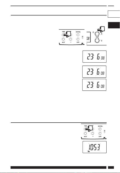
Ustawianie daty
Nacisnąć i przytrzymać Λ oraz PROG przez 3 sekundy w celu
wyświetlenia daty w formacie dd/mm/rr (dd/mm/yy).
Liczba ROK (YEAR) zacznie migać – skorygować
rok przy użyciu Λ lub V.
Przy pomocy “-” lub “+” przejść do MIESIĄC
(MONTH) – skorygować miesiąc przy użyciu Λ lub
V.
Przy pomocy “-” lub “+” przejść do DZIEŃ (DATE)
w miesiącu – skorygować dzień w miesiącu przy
użyciu Λ lub V.
Przy próbie wprowadzenia nieistniejącego w miesiącu dnia
oprogramowanie urządzenia odrzuci go i wprowadzi najbliższy
istniejący dzień. Zaleca się wpisywanie daty w kolejności rok-miesiącdzień.
Ustawianie godziny
Po ustawieniu daty nacisnąć PROG, aby wyświetlić
godzinę (cyfry oznaczające godzinę zaczną
migać).
Przy pomocy przycisków “-” i “+” ustawić godzinę
(nacisnąć i przytrzymać, aby wskazanie zmieniało
się w odstępach dziesięciominutowych).
GB
PL
DANFOSS HEATING 59
Page 60

Ustawianie dnia tygodnia
Dzień tygodnia jest ustawiany automatycznie.
Nacisnąć PROG w celu powrotu do trybu pracy
(RUN).
Akceptacja wstępnie ustawionych programów
Jeśli użytkownikowi odpowiadają ustawienia przedstawione w tabeli
na stronie 57, nie musi on wykonywać żadnych działań.
Zmiana wstępnie ustawionych programów
Przed zmianą wstępnie ustawionych programów
Instalator ustawił urządzenie w jednym z następujących trybów:
7-dniowy – każdy dzień ma niezależne godziny i temperatury, co
umożliwia w pełni elastyczne programowanie (strona 61)
5/2 dni – jeden zestaw programów na dni powszednie i drugi na
weekendy (strona 62)
24-godzinny – jeden zestaw programów na cały tydzień (strona 63).
Alternatywnie
opcja A/B – Urządzenie może także być ustawione przez
użytkownika w dwóch blokach programowych, z których każdy
może być zastosowany dla różnych dni tygodnia. W razie potrzeby
włączenia tej funkcji należy skorzystać ze wskazówek na stronie
63.
Uwaga
Urządzenie trzeba programować w odpowiedniej kolejności – nawet
godziny nie mogą być wprowadzane w dowolnej sekwencji.
Jeśli nie ma potrzeby zmiany wstępnie ustawionej godziny, należy
nacisnąć NEXT, aby przejść do następnej pozycji.
Aby termostat powrócił do normalnego trybu (RUN), należy nacisnąć
PROG i przytrzymać tak długo, aż wyświetlacz wróci do poprzedniego
trybu RUN. Można też nie wykonywać żadnych czynności, a urządzenie
automatycznie wróci do trybu RUN po 2 minutach.
60
TP9000
Page 61

Instalator ustawi termostat na 6, 4 lub 2 zmiany każdego dnia dla
ogrzewania i/lub 3, 2 lub 1 zmianę każdego dnia dla ciepłej wody. Te
ustawienia określają dzienną liczbę zmian, które użytkownik może
samodzielnie programować.
Należy pamiętać, aby przed rozpoczęciem programowania
sprawdzić, czy została wybrana odpowiednia funkcja, tzn.
ogrzewanie lub ciepła woda (w razie potrzeby skorygować funkcję
przyciskiem CH/HW).
Zmiana wstępnie ustawionych programów w trybie
7-dniowym
a) Naciskać PROG, aż wyświetlacz pokaże
pierwszą wstępnie ustawioną godzinę i
temperaturę.
b) Przy pomocy przycisków “-” i “+” skorygować godzinę (nacisnąć
i przytrzymać, aby wskazanie zmieniało się w odstępach
dziesięciominutowych).
c) Przy pomocy przycisków Λ i V wprowadzić wymaganą
temperaturę (tylko ogrzewanie).
d) Nacisnąć NEXT, aby przejść do następnej
wstępnie ustawionej godziny i/lub temperatury
(nastawa 2).
e) Gdy wszystkie nastawy dla danego dnia zostaną
zaprogramowane, nacisnąć DAY/HOL, aby przejść do następnego
dnia
f) Powtarzać kroki b, c, d oraz e, aby zaprogramować nastawy dla
pozostałych dni tygodnia.
g) Nacisnąć i przytrzymać PROG, aby powrócić do głównego
ekranu.
DANFOSS HEATING 61
GB
PL
Page 62
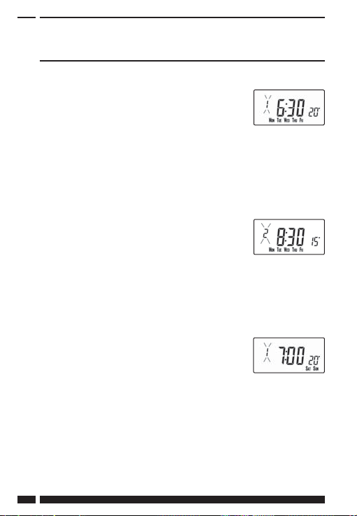
Zmiana wstępnie ustawionych programów w
trybie 5/2 dni
Dla dni powszednich
a) Naciskać PROG, aż wyświetlacz pokaże pierwszą
wstępnie ustawioną godzinę i temperaturę
(nastawa 1, dni MON, TUE, WED, THU, FRI)
b) Przy pomocy przycisków “-” i “+” skorygować godzinę (nacisnąć
i przytrzymać, aby wskazanie zmieniało się w odstępach
dziesięciominutowych).
c) Przy pomocy przycisków Λ i V wprowadzić wymaganą temperaturę
(tylko ogrzewanie).
d) Nacisnąć NEXT, aby przejść do następnej
wstępnie ustawionej godziny i/lub temperatury
(nastawa 2).
e) Powtarzać kroki b, c oraz d, aby zaprogramować
pozostałe nastawy dla dni powszednich.
f) Nacisnąć DAY/HOL, aby przejść do nastaw weekendowych.
Dla Weekendów
Naciskać PROG, aż wyświetlacz pokaże pierwszą
wstępnie ustawioną godzinę i temperaturę
(nastawa 1, dni SAT, SUN).
Powtarzać kroki b, c oraz d powyżej, aby zaprogramować pozostałe
nastawy weekendowe.
Nacisnąć i przytrzymać PROG, aby powrócić do głównego ekranu.
62
TP9000
Page 63
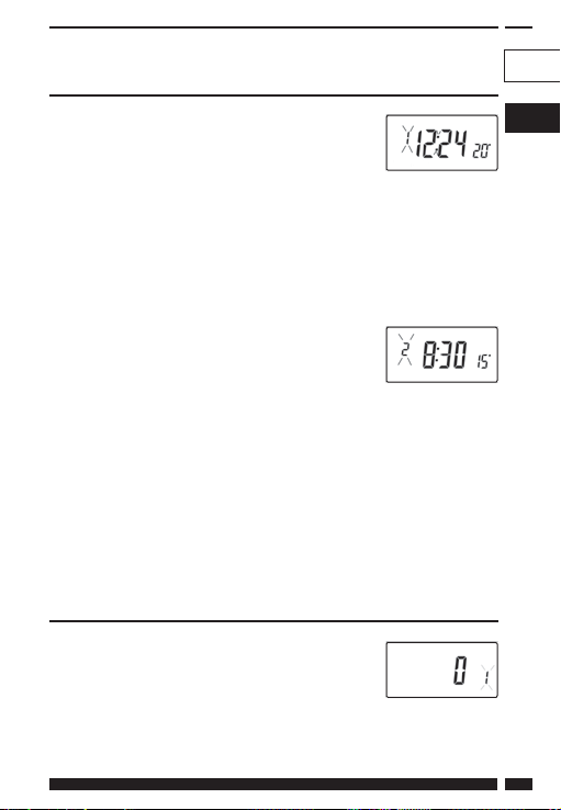
Zmiana wstępnie ustawionych programów w trybie
24-godzinnym
a) PrNaciskać PROG, aż wyświetlacz pokaże
pierwszą wstępnie ustawioną godzinę i
temperaturę (nastawa 1, wszystkie dni
tygodnia).
b) Przy pomocy przycisków “-” i “+” skorygować godzinę (nacisnąć
i przytrzymać, aby wskazanie zmieniało się w odstępach
dziesięciominutowych).
c) Przy pomocy przycisków Λ i V wprowadzić wymaganą temperaturę
(tylko ogrzewanie).
d) Nacisnąć NEXT, aby przejść do następnej
wstępnie ustawionej godziny i/lub
temperatury (nastawa 2).
e) Powtarzać kroki b, c oraz d, aby zaprogramować pozostałe
nastawy.
f) Nacisnąć DAY/HOL, aby przejść do nastaw weekendowych.
Zmiana wstępnie ustawionych programów w opcji
A/B programming
(funkcja 41 programowana przez instalatora musi być ustawiona na
tryb 5-2 dni)
Nacisnąć i przytrzymać przez 3 sekundy PROG i V,
aby wejść w funkcję 1 w trybie zaawansowanych
funkcji programowanych przez użytkownika;
wskazania wyświetlacza zilustrowane są obok.
GB
PL
DANFOSS HEATING 63
Page 64

Przy pomocy przycisków Λ i V włączyć lub wyłącz yć
funkcję (1 = włączona, 0 = wyłączona).
Nacisnąć i przytrzymać przez 5 sekund PROG, aby
wyświetlacz wrócił do poprzedniego trybu RUN.
Nacisnąć PROG raz – wyświetlacz pokaże domyślne
dni przypisane do programu “A” (te dni to: MON,
TUE, WED, THU, FRI).
Posługując się przyciskami “+” i “–”, przewijać dni
tygodnia w przód i w tył.
Aby usunąć dzień, należy nacisnąć V (np. TUE). Aby
dodać dzień, należy nacisnąć Λ (np. SUN).
Wszystkie usunięte dni zostaną automatycznie przypisane do
programu “B”.
Wprowadzanie nastaw w programie “A”
a) Naciskać PROG, aż wyświetlacz pokaże
pierwszą wstępnie ustawioną godzinę i/lub
temperaturę (nastawa 1, program “A”).
b) Przy pomocy przycisków “-” i “+” skorygować
godzinę (nacisnąć i przytrzymać, aby wskazanie zmieniało się w
odstępach dziesięciominutowych).
c) Przy pomocy przycisków Λ i V wprowadzić wymaganą
temperaturę (tylko ogrzewanie).
d) Nacisnąć NEXT, aby przejść do następnej wstępnie ustawionej
godziny i/lub temperatury (nastawa 2).
e) Powtarzać kroki b, c oraz d, aby zaprogramować pozostałe
nastawy.
64
TP9000
Page 65
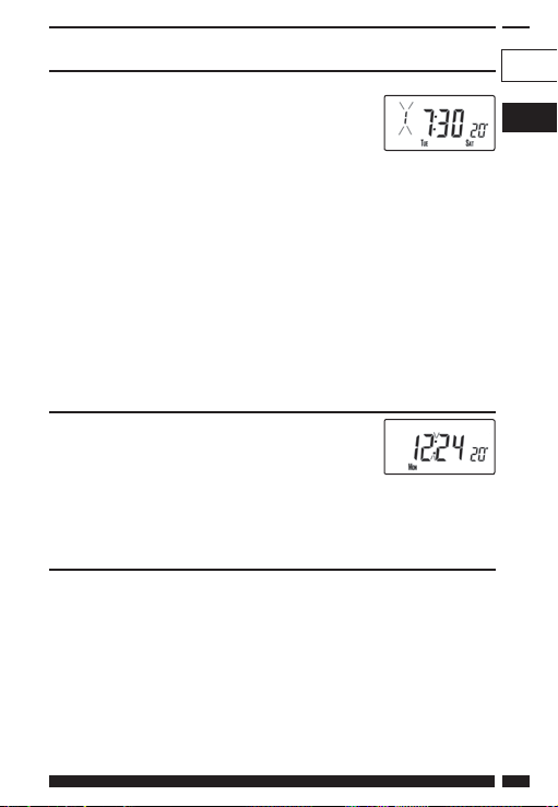
Wprowadzanie nastaw w programie “B”
a) Naciskać DAY/HOL, aż wyświetlacz pokaże
pierwszą wstępnie ustawioną godzinę i
temperaturę (nastawa 1, program “B”).
b) Przy pomocy przycisków “-” i “+” skorygować godzinę (nacisnąć
i przytrzymać, aby wskazanie zmieniało się w odstępach
dziesięciominutowych).
c) Przy pomocy przycisków Λ i V wprowadzić wymaganą temperaturę
(tylko ogrzewanie).
d) Nacisnąć NEXT, aby przejść do następnej wstępnie ustawionej
godziny i/lub temperatury (nastawa 2).
e) Powtarzać kroki b, c oraz d, aby zaprogramować pozostałe
nastawy.
Uruchamianie programu
Nacisnąć PROG, aby powrócić do poprzedniego
trybu RUN. Centralne ogrzewanie będzie teraz
funkcjonować zgodnie z zaprogramowanymi
godzinami i temperaturami.
Wyjaśnienie funkcji kopiowania
Dostępne są dwie funkcje kopiowania: kopiowanie standardowe i
kopiowanie rozszerzone. Funkcje kopiowania są włączane i wyłączane
w funkcjach programowania zaawansowanego (strona 75).
Kopiowanie standardowe: Naciśnięcie przycisku COPY spowoduje
skopiowanie nastaw z dnia poprzedniego do dnia wyświetlanego.
Urządzenie pokaże następnie pierwszą nastawę dla nowego dnia.
Ta funkcja kopiowania jest aktywna tylko wtedy, gdy urządzenie jest
ustawione w trybie 5+2 dni lub trybie 7-dniowym.
GB
PL
DANFOSS HEATING 65
Page 66

Kopiowanie rozszerzone: Funkcja kopiowania rozszerzonego jest
dostępna tylko w trybie 7-dniowym. Pozwala ona na skopiowanie
dowolnego dnia do dowolnego innego dnia lub dni. Aby zastosować
funkcję kopiowania rozszerzonego, należy wejść w tryb programowania
nastaw za pomocą przycisku PROG, a następnie:
1) za pomocą przycisku DAY znaleźć dzień, z którego nastawy
mają być kopiowane
2) nacisnąć przycisk CO PY, aby wybrać dzień, z którego nastawy
mają być kopiowane – po wybraniu dzień powinien zacząć
migać
3) za pomocą przycisku DAY znaleźć dzień, do którego nastawy
mają być kopiowane
4) nacisnąć przycisk COPY, aby skopiować wybrany dzień
5) powtarzać kroki 3 i 4, aby wybrać i skopiować do innych
6) aby zakończyć kopiowanie, za pomocą przycisku DAY
dni
wrócić do dnia migającego i nacisnąć przycisk COPY.
Dzień ten przestanie migać, co będzie oznaczać, że nie jest
już aktywny.
Program wakacyjny
Termostat TP9000 posiada także tryb wakacyjny, który umożliwia
automatyczne przywrócenie funkcji ogrzewania i ciepłej wody po
powrocie z wakacji. W okresie, w którym urządzenie jest w trybie
wakacyjnym, ciepła woda jest wyłączona, a centralne ogrzewanie jest
w trybie ochrony przed mrozem.
Aby ustawić program wakacyjny, należy postępować następująco:
a) Nacisnąć i przytrzymać przycisk DAY/HOL.
b) Przy pomocy przycisków Λ i V wprowadzić
rok.
66
TP9000
Page 67

c) Przy pomocy przycisków “-” i “+” przejść do
ustawiania miesiąca. Przy pomocy Λ i V
wprowadzić miesiąc.
d) Przy pomocy przycisku “+” przejść do
ustawiania dnia. Przy pomocy Λ i V
wprowadzić dzień.
e) Aby zakończyć ustawianie i uruchomić
tryb wakacyjny, należy raz nacisnąć DAY/
HOL. Wyświetlacz zmieni się, ogrzewanie
i ciepła woda zostaną wyłączone.
Urządzenie pozostanie w tym trybie do
zaprogramowanego dnia powrotu, w
którym zacznie znów funkcjonować w
zwykły sposób.
f ) W trybie wakacyjnym można ustawić tryby prz ywrócenia zarówno
ogrzewania, jak i ciepłej wody. Przy pomocy przycisku CH/HW
przejść z trybu wyświetlania ogrzewania do trybu wyświetlania
ciepłej wody lub na odwrót.
g) Wymagana temperatura (dla ogrzewania) w czasie obowiązywania
trybu wakacyjnego może być ustawiana przez wybranie trybu
wyświetlania ogrzewania za pomocą przycisku CH/HW, a
następnie ustawienie przy pomocy przycisków Λ i V.
h) Tryb wakacyjny może być wyłączony ręcznie, w dowolnym czasie,
przez naciśnięcie przycisku DAY.
GB
PL
DANFOSS HEATING 67
Page 68

Zmiany ręczne
dokonywane przez
użytkownika
Przestawianie wyświetlacza, aby pokazywał
godzinę lub temperaturę (tryb ogrzewania)
Nacisnąć jednocześnie “-” i “+”,
aby zmienić ustawienie na
alternatywne.
Tymczasowa zmiana uprzednio zaprogramowanej
temperatury
Nacisnąć i przytrzymać Λ lub V, aż pojawi się wymagana temperatura.
Należy pamiętać o tym, że instalator mógł ograniczyć możliwość
ustawienia zarówno górnej i dolnej temperatury, jak i zakres ręcznej
zmiany temperatury.
Ręczne ustawienie zostanie automatycznie anulowane na początku
następnej zaprogramowanej nastawy. Należy pamiętać o tym, że
instalator mógł ograniczyć czas trwania ręcznej zmiany inaczej niż do
następnej nastawy. W takim przypadku strzałka ręcznej zmiany będzie
migać, aby wskazać, że tymczasowa zmiana obowiązuje podczas
następnej nastawy.
Zmiana oznaczeń dni tygodnia z cyfrowych na
słowne
Nacisnąć jednocześnie Λ i “-”, aby zmienić oznaczenia dni tygodnia z
cyfrowych na słowne lub na odwrót.
68
TP9000
Page 69

Zmiana formatu wyświetlania czasu
Nacisnąć jednocześnie Λ i “+”, aby zmienić format wyświetlania czasu z
dwunastogodzinnego na dwudziestoczterogodzinny lub na odwrót
Zmiana skali termometrycznej
Nacisnąć jednocześnie V i “-”, aby zmienić skalę Celsjusza (°C) na skalę
Fahrenheita (°F) lub na odwrót.
Tryb termostatyczny (tylko tryb ogrzewania)
a) W razie potrzeby można zaprogramować stałą temperaturę z
przedziału 5-30 °C. Ta funkcja urządzenia może być wykorzystywana
dla ochrony wyposażenia domu przed skutkami mrozu w czasie
dłuższego wyjazdu lub dla utrzymywania niezaprogramowanej
wcześniej wyższej temperatury (na przykład podczas choroby
domownika).
b) Nacisnąć jednocześnie Λ i V, aby wejść w tryb termostatyczny.
Temperatura domyślna to 5°C, ale może ona być zmieniona –
szczegółowe informacje znajdują się w części dotyczącej funkcji
zaawansowanych programowanych przez użytkownika (krok 10,
strona 77).
c) Symbol ochrony przed mrozem (płatek śniegu
na tarczy) pojawi się na wyświetlaczu, jeśli
wybrana temperatura będzie równa lub niższa
od zaprogramowanego ustawienia ochrony
przed mrozem.
d) Przy pomocy przycisków Λ lub V zmienić zaprogramowaną
temperaturę chroniącą przed mrozem na inną wartość.
e) Nacisnąć jednocześnie Λ i V, aby wrócić do programu
automatycznego.
f) Do trybu termostatycznego można także wejść przy użyciu
przycisku MODE (strona 73).
GB
PL
DANFOSS HEATING 69
Page 70

Zmiana ustawienia zegara (w przód lub w tył)
Regulacja zegara odbywa się automatycznie. Jeśli jednak została
wybrana regulacja ręczna (funkcje zaawansowane programowane
przez użytkownika, krok 3, strona 34), należy skorzystać z poniższych
wskazówek.
Zmiana czasu z letniego na zimowy (cofnięcie zegara)
Po wyświetleniu zegara należy nacisnąć i przytrzymać przycisk “-”, aż
czas zostanie cofnięty.
Zmiana czasu z zimowego na letni (przesunięcie zegara do przodu)
Po wyświetleniu zegara należy nacisnąć i przytrzymać przycisk “+”, aż
czas zostanie przesunięty do przodu.
Zdalne włączanie lub wyłączanie trybu
termostatycznego
Niektóre modele posiadają funkcję umożliwiającą wprowadzanie
urządzenia w tryb termostatyczny przy pomocy telefonu lub styków
okiennych.
Temperatura wymagana podczas nieobecności użytkowników
budynku lub gdy okna są otwarte musi najpierw być ustawiona w
zaawansowanej funkcji programowanej przez użytkownika (krok 10,
strona 77).
Aby zmienić zdalnie wprowadzone ustawienia bezpośrednio na
urządzeniu, należy nacisnąć jednocześnie Λ i V lub przycisk MODE.
Funkcja opóźniania załączenia
Termostat posiada opcjonalną funkcję opóźniania momentu
załączenia ogrzewania, aby obniżyć zużycie energii w cieplejsze dni,
gdy temperatura wewnątrz budynku na początku nastawy jest bliska
zaprogramowanej wartości. Jeśli ta funkcja została włączona, może
być ona tymczasowo (ręcznie) zmieniona po naciśnięciu przycisku Λ
lub V. Aby włączyć tę funkcję, należ postępować według wskazówek
70
TP9000
Page 71

dotyczących zaawansowanego programowania przez użytkownika
(krok 11, strona 77).
Gdy ta funkcja jest aktywna, zadana temperatura miga na wyświetlaczu
i widoczny jest symbol klepsydry.
Optymalizacja momentu załączenia
Termostat posiada opcjonalną funkcję optymalizacji momentu
załączenia. Umożliwia ona zaprogramowanie godziny, o której
temperatura w pomieszczeniu powinna osiągnąć zadaną wartość.
Urządzenie obliczy automatycznie, z jakim wyprzedzeniem ogrzewanie
musi zostać włączone, aby pokój był odpowiednio nagrzany o
wymaganej godzinie. Pełny opis tej funkcji wraz ze sposobem jej
uruchomiania i ustawiania znajduje się w części dotyczącej zaa
wansowanego programowania przez użytkownika (kroki 12 i 13,
strona 78). Gdy ta funkcja jest aktywna, zadana temperatura miga na
wyświetlaczu.
GB
PL
DANFOSS HEATING 71
Page 72
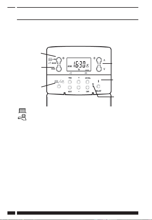
Przyciski tymczasowej zmiany ręcznej
Niekiedy może zaistnieć potrzeba tymczasowej zmiany
zaprogramowanych ustawień ogrzewania, na przykład podczas silnych
mrozów. Model TP9000 oferuje dwie przydatne funkcje, które mogą
zostać wybrane bez wpływu na zaprogramowane ustawienia.
+1/+2/+3 godz.
jednorazowo
przycisk wyboru
trybu (auto/cały
dzień/wł/wył))
przycisk
ogrzewanie/
ciepła woda
+ HRS
Szary przycisk obok symboli grzejnika i kranu to przycisk
“+ HRS” dla ogrzewania i BOOST dla ciepłej wody.
BOOST
Gdy wyświetlacz jest w trybie ciepłej wody, naciśnięcie
Gdy wyświetlacz jest w trybie ogrzewania, naciśnięcie
72
przycisku BOOST jeden, dwa lub trzy razy, gdy układ jest
w trybie OFF, AUTO lub ALLDAY (cały dzień), spowoduje,
że ciepła woda pozostanie załączona przez dodatkowy
okres (1, 2 lub 3 godz.), jeśli jest już włączona, lub wymusi
jej załączenie na zadany okres (1, 2 lub 3 godz.), jeśli jest
wyłączona. Na wyświetlaczu ukażą się symbole BOOST +1,
+2 lub +3 HRS.
przycisku +HRS jeden, dwa lub trzy razy przedłuży
aktualną nastawę o dodatkowy okres (1, 2 lub 3 godz.).
Funkcja ta jest nieaktywna, gdy termostat jest w trybie
OFF (wyłączony) lub FROST PROTECTION (ochrona przed
mrozem). Na wyświetlaczu ukażą się symbole +1, +2 lub
+3 HRS. Naciśnięcie tego przycisku po raz czwarty wyłącz y
funkcję +HRS BOOST
przyciski
regulacji temperatury
przycisk INFO
przycisk
RESET
TP9000
Page 73

MODE Naciskanie tego przycisku powoduje przełączanie między
Wskazuje, że urządzenie jest w trybie ALLDAY lub AUTO z
Wskazuje, że urządzenie jest w trybie AUTO z 4 nastawami
Wskazuje, że urządzenie jest w trybie AUTO z 6 nastawami
ON Wskazuje, że ciepła woda jest włączona na stałe (dotyczy
OFF Wskazuje, że ciepła woda jest na stałe wyłączona lub tryb
Naciśnięcie przycisku INFO spowoduje wyświetlenie
i
trybami OFF (termostat), AUTO lub ALLDAY dla ogrzewania
albo trybami ON, OFF, AUTO lub ALLDAY dla ciepłej wody.
W trybie AUTO będą aktywne wszystkie zaprogramowane
nastawy, podczas gdy w trybie ALLDAY będzie aktywna
tylko pierwsza i ostatnia zaprogramowana nastawa. W
przypadku zaprogramowania dwóch nastaw dziennie
dla ogrzewania lub jednej nastawy ON/OFF dziennie dla
ciepłej wody tryby AUTO oraz ALLDAY są takie same.
Wyświetlacz pokaże liczbę ustawionych nastaw:
2 nastawami dziennie dla ogrzewania lub 1 nastawą ON/
OFF dziennie dla ciepłej wody.
dziennie dla ogrzewania lub 2 nastawami ON/OFF dziennie
dla ciepłej wody.
dziennie dla ogrzewania lub 3 nastawami ON/OFF dziennie
dla ciepłej wody.
tylko ciepłej wody).
termostatyczny ogrzewania jest nieaktywny (strona 69).
informacji o następnej zaprogramowanej nastawie dla
aktualnego trybu (centralne ogrzewanie lub ciepła woda),
temperaturze zewnętrznej (jeśli jest zainstalowany czujnik
zewnętrzny) i dacie najbliższego przeglądu serwisowego
(jeśli została ustawiona). Poniżej znajduje się szczegółowy
opis tej funkcji.
GB
PL
DANFOSS HEATING 73
Page 74

Jeśli nie zainstalowano czujnika zewnętrznego:
Naciśnięcie przycisku INFO spowoduje wyświetlenie
godziny następnej nastawy zgodnej z zaprogramowanym
ustawieniem. Godzina pokazanej nastawy będzie
uwzględniać ewentualne przedłużenia +HRS lub BOOST.
Jeżeli czas następnej nastawy będzie migać, będzie
to oznaczać, że jest to godzina przybliżona, gdyż jest
aktywna funkcja optymalizacji momentu załączenia
(Optimum Start), opóźniania załączenia (Delayed Start) lub
użytkownik dokonał tymczasowej zmiany ręcznej.
Jeśli zainstalowano czujnik zewnętrzny:
Naciśnięcie przycisku INFO spowoduje wyświetlenie
aktualnej temperatury zewnętrznej, a następnie najniższej
i najwyższej temperatury zewnętrznej w ciągu ostatnich
24 godzin.
Jeśli ustawiono datę najbliższego przeglądu
serwisowego:
Naciśnięcie przycisku INFO spowoduje wyświetlenie daty,
kiedy powinien zostać dokonany najbliższy przegląd
serwisowy.
Jeśli włączony jest tryb wakacyjny:
Naciśnięcie przycisku INFO spowoduje wyświetlenie
końcowej daty trybu wakacyjnego.
74
TP9000
Page 75

Zaawansowane funkcje
GB
programowane przez
użytkownika
Ważne: Termostat został zaprogramowany w fabryce w sposób
optymalny dla większości sytuacji. Przewidziano jednak dodatkowe,
opcjonalne ustawienia, które mogą zwiększyć funkcjonalność
urządzenia i wygodę jego użytkowania oraz zmniejszyć zużycie energii.
Są to zaawansowane funkcje programowane przez użytkownika
oraz zaawansowane funkcje programowane przez instalatora.
Wejście w tryb zaawansowanych funkcji
programowanych przez użytkownika
Nacisnąć i przytrzymać przez 3 sekundy V i PROG, aby wejść w tryb
zaawansowanych funkcji programowanych przez użytkownika.
Posługując się przyciskami “+” i “–”, przewijać funkcje w przód i w
tył, a następnie przy pomocy przycisków V i Λ zmienić ustawienia
funkcji. Migająca cyfra po prawej stronie wyświetlacza pokazuje numer
wybranej funkcji.
Funkcja 1 – Włączenie lub wyłączenie programu A/B (funkcja 41 i/
lub 61 ustawiona na 5+2)
Za pomocą tej funkcji można włączyć lub wyłączyć
opcję programową A/B. Naciskać “+” tak długo, aż
wyświetli się funkcja 1, a następnie przy pomocy V i Λ
wybrać żądane ustawienie.
Ustawienie 0 Wyłączona; urządzenie pracuje w opcji 5+2
Ustawienie 1 Włączona; opcja A/B aktywna
PL
DANFOSS HEATING 75
Page 76

Funkcja 2 – Włączenie lub wyłączenie programowania
zaawansowanego (funkcja 41 i/lub 61 ustawiona na tryb 7 dni)
Za pomocą tej funkcji można włączyć lub wyłączyć
kopiowanie zaawansowane. Naciskać “+” tak długo,
aż wyświetli się funkcja 2, a następnie przy pomocy
V i Λ wybrać żądane ustawienie.
Ustawienie 0
Kopiowanie zaawansowane wyłączone (tryb
kopiowania standardowego)
Ustawienie 1 Kopiowanie zaawansowane włączone
Funkcja 3 – Regulacja zegara kalendarzowego
Za pomocą tej funkcji można ustawić sposób, w
jaki automatyczny zegar kalendarzowy będzie
regulowany przy zmianie czasu z letniego na zimowy
lub na odwrót. Naciskać “+” tak długo, aż wyświetli
się funkcja 3, a następnie przy pomocy V i Λ wybrać
żądane ustawienie.
Ustawienie 0 Wyłączona.
Ręczna: użytkownik musi wykonać regulację
Ustawienie 1
samodzielnie, używając przycisku “+”, aby posunąć
zegar do przodu, i przycisku “-”, aby go cofnąć
Ustawienie 2 System europejski (ustawienie fabryczne)
Ustawienie 3 System amerykański (USA) (rok 2007 i później)
Ustawienie 4 System amerykański (USA) (przed rokiem 2007)
Funkcja 4 – Ustawianie strefy czasowej
Za pomocą tej funkcji można ustawić strefę czasową
i skorygować wskazania wyświetlacza. Naciskać “+”
tak długo, aż wyświetli się funkcja 4, a następnie przy
pomocy V i Λ wybrać żądane ustawienie.
Modele przeznaczone na rynek Zjednoczonego
Ustawienie 0
Królestwa: ta funkcja powinna być pozostawiona na
ustawieniu fabrycznym, tj. 0
Modele przeznaczone na rynek środkowoeuropejski:
Ustawienie 1
ta funkcja powinna być pozostawiona na ustawieniu
fabrycznym, tj. +1:00
76
TP9000
Page 77

-12 godzin +14 godzin
Modele przeznaczone na pozostałe rynki: przy pomocy prz ycisków Λ i
V wprowadzić różnicę względem czasu uniwersalnego (UTC, GMT) dla
miejsca, w którym termostat jest użytkowany
Funkcja 10 – Ustawienie trybu ochrony przed mrozem lub trybu
termostatycznego
Za pomocą tej funkcji można ustawić temperaturę dla trybu
ochrony przed mrozem lub dla trybu termostatycznego.
Naciskać “+” tak długo, aż wyświetli się funkcja 10, a
następnie przy pomocy V i Λ wybrać żądane ustawienie.
5-40°C – Ustawienie fabryczne to 5 °C, ale może być ono zmienione na
dowolną wartość z przedziału 5-40 °C.
Funkcja 11 – Sposób załączania
Termostat może załączyć układ na trzy różne sposoby.
Naciskać “+” tak długo, aż wyświetli się funkcja 11, a
następnie przy pomocy V i Λ wybrać żądane ustawienie.
Ustawienie 0 Normalny: Ogrzewanie jest załączane i wyłączane o
Ustawienie 1 Optymalizacja momentu załączenia (ustawienie
Ustawienie 2 Opóźnianie załączenia (ustawienie ekonomiczne): Jest
DANFOSS HEATING 77
zaprogramowanych porach.
komfortowe): To ustawienie umożliwia wcześniejsze
zaprogramowanie godziny, o której temperatura
w pomieszczeniu powinna osiągnąć zadaną
wartość. Urządzenie obliczy automatycznie, z jakim
wyprzedzeniem ogrzewanie musi zostać włączone,
aby pokój był odpowiednio nagrzany o wymaganej
godzinie. Wyprzedzenie to będzie zależeć od warunków
pogodowych i wahać się w przedziale od maksymalnie
120 minut do 0 przed zaprogramowanym terminem
nastawy. To ustawienie musi być stosowane łącznie
z funkcją 12, w której należy dobrać ustawienie
optymalizacyjne do właściwości budynku.
to ustawienie alternatywne względem optymalizacji
momentu załączenia. Należy zaprogramować pory
nastaw w zwykły sposób, biorąc pod uwagę przeciętny
czas, jaki potrzebuje budynek, aby się nagrzać do
wymaganej temperatury. Termostat sprawdza najbliższy
czas załączenia, temperaturę rzeczywistą i temperaturę
zadaną i opóźnia włączenie ogrzewania, jeśli temperatura
rzeczywista jest bliska temperaturze zaprogramowanej.
GB
PL
Page 78

Funkcja 12 – Ustawienie optymalizacyjne dla optymalizacji
momentu załączenia (funkcja 11 ustawiona na 1)
Naciskać “+” tak długo, aż wyświetli się funkcja
12, a następnie przy pomocy V i Λ wybrać żądane
ustawienie (aktywna tylko, gdy funkcja 11 jest
ustawiona na 1).
Optymalizacja momentu załączenia musi uwzględniać charakterystykę
cieplną budynku. Przy pomocy przycisków Λ i V należy wybrać
właściwy czas nagrzewania budynku. W poniższej tabeli można
znaleźć typowe ustawienia.
Jeśli budynek nie osiąga zaprogramowanej temperatury w
odpowiednim czasie, należy zwiększać ustawienie o 15 minut każdego
dnia, aż do znalezienia właściwej długości wyprzedzenia.
Jeśli budynek osiąga zaprogramowaną temperaturę przed czasem,
należy zmniejszać ustawienie o 15 minut każdego dnia, aż do
znalezienia właściwej długości wyprzedzenia.
0:15
15 minut; ogrzewanie ciepłym powietrzem, budynek bardzo
dobrze izolowany
0:30
30 minut; ogrzewanie ciepłym powietrzem, budynek dość
dobrze izolowany
0:45
45 minut; ogrzewanie ciepłym powietrzem, budynek słabo
izolowany
1:00
60 minut; ogrzewanie grzejnikami, lekka konstrukcja, budynek
dobrze izolowany (ustawienie fabryczne)
1:15
75 minut; ogrzewanie grzejnikami, lekka konstrukcja, budynek
średnio izolowany
1:30
90 minut; ogrzewanie grzejnikami, średnia konstrukcja, budynek
słabo izolowany
1:45
105 minut; ogrzewanie grzejnikami, ciężka konstrukcja, budynek
dobrze izolowany
2:00
120 minut; ogrzewanie grzejnikami, ciężka konstrukcja, budynek
słabo izolowany
78
TP9000
Page 79

Funkcja 13 – Wybieranie nastaw, do których stosowana będzie
optymalizacja momentu załączenia lub opóźnianie załączenia
(funkcja 11 ustawiona na 1 lub 2)
Optymalizacja momentu załączenia lub opóźnianie
załączenia może być przypisane tylko do pierwszej
nastawy lub alternatywnie do każdej nastawy w
danym dniu, która wymaga wyższej temperatury niż
nastawa poprzedzająca. Naciskać “+” tak długo, aż
wyświetli się funkcja 13, a następnie przy pomocy
V i Λ wybrać żądane ustawienie (aktywna tylko, gdy
funkcja 11 jest ustawiona na 1 lub 2).
Ustawienie 0 Dotyczy tylko pierwszej nastawy w danym dniu
(ustawienie fabryczne)
Ustawienie 1 Dotyczy każdej nastawy w danym dniu, która
wymaga wyższej temperatury w porównaniu z
nastawą poprzedzającą
GB
PL
DANFOSS HEATING 79
Page 80

Przegląd funkcji ustawianych przez
instalatora, które mogą wpływać na
funkcjonowanie termostatu
Ograniczenie zakresu temperatur
Funkcja ta umożliwia instalatorowi zaprogramowanie zarówno
górnej, jak i dolnej granicy zakresu temperatury. Może to ograniczyć
najwyższą i najniższą wartość temperatury, którą użytkownik ustawia
samodzielnie na termostacie.
Ograniczenie zakresu tymczasowej ręcznej zmiany
zadanej wartości temperatury
Funkcja ta umożliwia instalatorowi ograniczenie liczby stopni, o którą
użytkownik może chwilowo zmienić zaprogramowaną temperaturę.
Za pomocą innej funkcji instalator ustawia czas obowiązywania
tymczasowej zmiany temperatury wprowadzonej przez użytkownika.
Blokada klawiatury
Funkcja ta pozwala instalatorowi ograniczyć funkcjonalność klawiatury
lub ją zablokować w celu uniemożliwienia zmiany zaprogramowanych
parametrów przez osoby nieuprawnione.
80
TP9000
Page 81

Wskaźnik czasu następnego przeglądu
GB
Jeśli termostat jest instalowany w lokalu
przeznaczonym na wynajem, właściciel
może poprosić instalatora o ustawienie
wskaźnika czasu następnego przeglądu
serwisowego. Jest to zalecane ze
względów bezpieczeństwa, zwłaszcza
gdy w lokalu jest ogrzewanie gazowe.
Jeśli funkcja ta zostanie ustawiona, 28
dni przed datą planowego przeglądu
urządzenie zacznie wydawać ostrzeżenia
wizualne i dźwiękowe, każdego dnia
w południe. Sygnał dźwiękowy będzie
trwał przez 10 sekund i będzie powtarzany co godzinę, dopóki nie
zostanie wyłączony przyciskiem. Po wyłączeniu sygnalizacja zostanie
wznowiona następnego dnia w południe.
Jeśli przegląd kotła nie zostanie wykonany przed planową datą,
urządzenie będzie również wydawać ostrzeżenia wizualne i
dźwiękowe, każdego dnia w południe. Sygnał dźwiękowy będzie
trwał przez 1 minutę i będzie powtarzany co godzinę, dopóki nie
zostanie wyłączony przyciskiem. Po wyłączeniu sygnalizacja zostanie
wznowiona następnego dnia w południe.
Dodatkowo wszystkie przyciski programowania oraz przyciski
służące do tymczasowych zmian ustawień będą zablokowane, a
ciepła woda i ogrzewanie mogą być dostępne przez ograniczony
czas co godzinę.
Instalator może całkowicie wyłączyć lub zresetować wskaźnik czasu
następnego przeglądu w ramach przeglądu kotła.
Funkcja ta związana jest z bezpieczeństwem gazowym i dostęp do
niej ma jedynie instalator.
Service Interval Date
PL
DANFOSS HEATING 81
Page 82

Resetowanie urządzenia
Resetowanie częściowe: Nacisnąć RESET (aby zrestartować
mikrokomputer), jeśli wyświetlacz zawiesi się z jakiegokolwiek
powodu. Nie resetuje to żadnego programu, zegara ani daty. Zaleca się
wykonanie resetowania podczas instalacji.
Resetowanie pełne przez użytkownika: Nacisnąć RESET, przytrzymując
jednocześnie przycisk PROG. Spowoduje to zresetowanie godzin nastaw
i wszystkich ustawień zaawansowanych funkcji programowanych przez
użytkownika. Czas ani data nie zostaną zresetowane.
Resetowanie pełne przez instalatora: Dostęp do niego ma tylko
instalator. Oprócz efektów wymienionych powyżej, wszystkie
zaawansowane funkcje programowane przez instalatora wracają
do ustawień fabrycznych. Czas, aktualna data oraz data najbliższego
przeglądu serwisowego nie zostaną zresetowane.
Ustawienia użytkownika
Funkcja Opis Ustawienie
Funkcja 1 Włączenie lub wyłączenie programu A/B
Funkcja 2 Włączenie lub wyłączenie programowania
Funkcja 3 Regulacja zegara kalendarzowego
Funkcja 4 Ustawianie strefy czasowej
Funkcja 10 Ustawienie trybu ochrony przed mrozem lub
Funkcja 11 Sposób załączenia
Funkcja 12 Ustawienie optymalizacyjne dla optymalizacji
Funkcja 13 Wybieranie nastaw, do których stosowana
zaawansowanego
trybu termostatycznego
momentu załączenia
będzie optymalizacja momentu załączenia lub
opóźnianie załączenia
użytkownika
82
TP9000
Page 83

Ustawienia instalatora
Funkcja Opis Ustawienie
Funkcja 30 Ustawianie górnej granicy zakresu
Funkcja 31 Ustawianie dolnej granicy zakresu temperatury
Funkcja 32 Umożliwienie wyłączenia poniżej dolnej
Funkcja 33 Umożliwienie włączenia powyżej górnej
Funkcja 34 Ustawienie On/Off (wł/w ył) lub
Funkcja 35 Ustawianie czasu całkowania
Funkcja 36 Ustawianie zakresu tymczasowej ręcznej
Funkcja 37 Ustawianie czasu obowiązywania tymczasowej
Funkcja 40 Dzienna liczba nastaw (ogrzewanie)
Funkcja 41 Tryb pracy (ogrzewanie)
Funkcja 60 Dzienna liczba nastaw (ciepła woda)
Funkcja 61 Tryb pracy (ciepła woda)
Funkcja 70 Ustawianie wariantu blokady klawiatury
Funkcja 71 Ustawianie załączenia zwłocznego
Funkcja 72 Numer referencyjny miejsca instalacji nadany
Funkcja 73 Numer referencyjny termostatu nadany przez
Funkcja 74 Format daty w zegarze kalendarzowym
Funkcja 80 Aktywacja/blokada przycisku zwiększania
Funkcja 81 Tolerancja kalibracji termostatu
Funkcja 90 Defi niowanie typu zdalnego czujnik a
Funkcja 93 Ustawianie wartości temperatury dla czujnika
Funkcja 94 Defi niowanie typu przełącznik a dla wejścia
temperatury
granicy
granicy
chronoproporcjonalności
zmiany zadanej wartości temperatury
ręcznej zmiany
przez właściciela
właściciela
liczby godzin
ograniczającego
cyfrowego
instalatora
GB
PL
DANFOSS HEATING 83
Page 84

www.danfoss.com/BusinessAreas/Heating
Part No 62052v01s1-00 03/08
84
TP9000
 Loading...