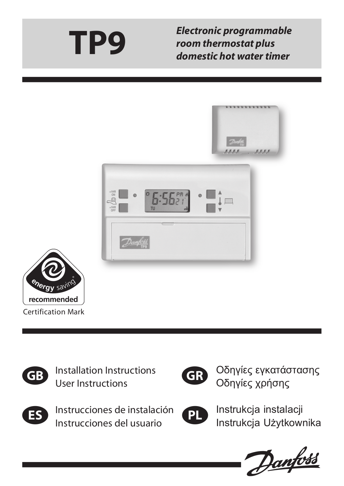
Danfoss TP9 User guide

Electronic programmable TP9 room thermostat plus

domestic hot water timer

®

Certification Mark

GB

ES

Installation Instructions

User Instructions

Instrucciones de instalación Instrucciones del usuario

GR

PL

ПдзгЯет егкбфЬуфбузт ПдзгЯет чсЮузт

Instrukcja instalacji Instrukcja Użytkownika

<![if ! IE]>

<![endif]>INDEX

Index

GB

Installation Instructions

3-6

Wiring

7-13


User Instructions

14-26

ES

Installation Instructions

27-30

Wiring

31-37


User Instructions

38-49

GR

Installation Instructions

50-53

Wiring

54-60


User Instructions

61-72

PL

Installation Instructions

73-76

Wiring

77-83


User Instructions

84-95

2

Installation Instructions

Please Note:

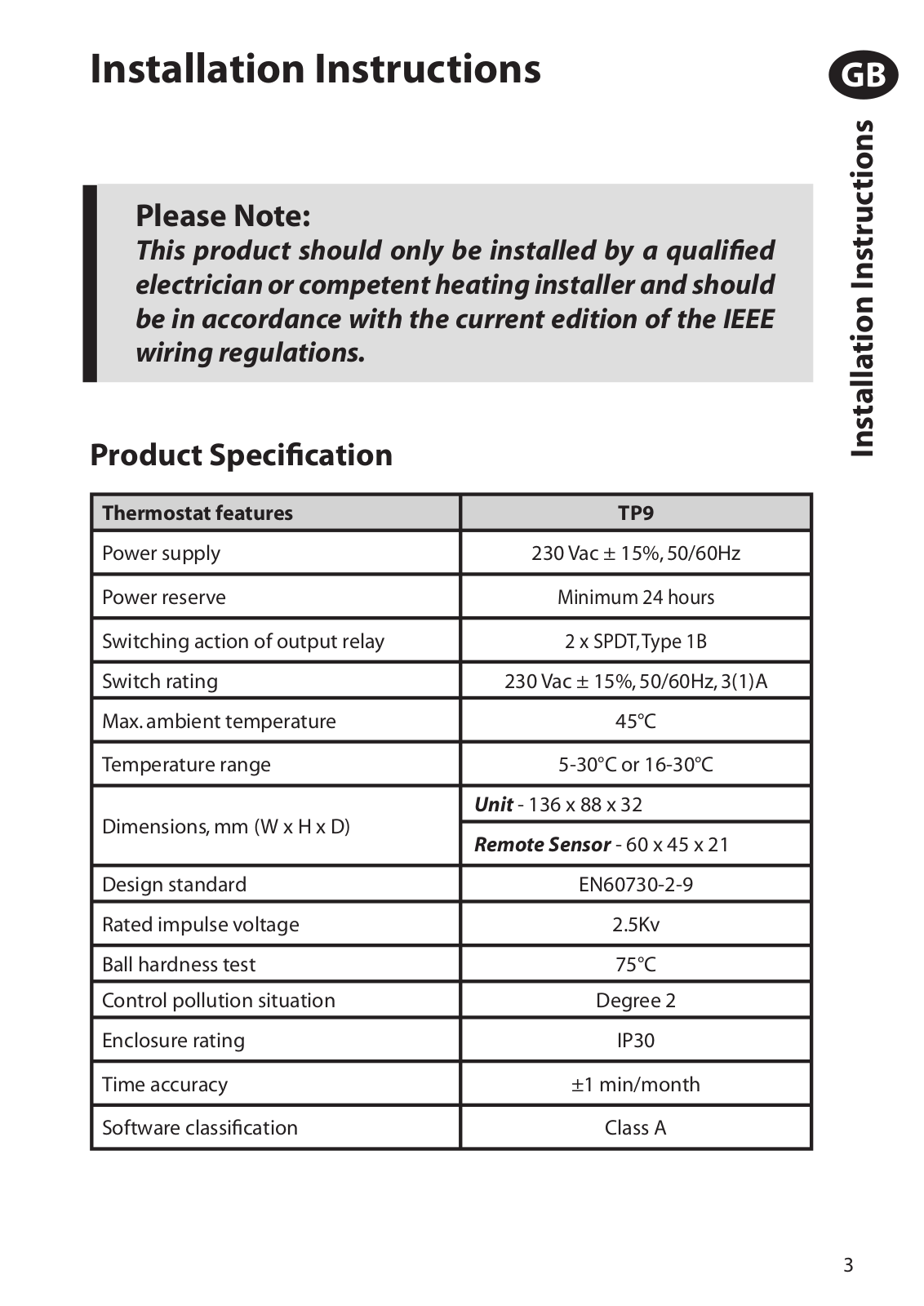
This product should only be installed by a qualified electrician or competent heating installer and should be in accordance with the current edition of the IEEE wiring regulations.

Product Specification

Thermostat features

TP9


Power supply

230 Vac ± 15%, 50/60Hz


Power reserve

Minimum 24 hours


Switching action of output relay

2 x SPDT,Type 1B


Switch rating

230 Vac ± 15%, 50/60Hz, 3(1)A


Max. ambient temperature

45°C


Temperature range

5-30°C or 16-30°C


Dimensions, mm (W x H x D)

Unit - 136 x 88 x 32


Remote Sensor - 60 x 45 x 21


Design standard

EN60730-2-9


Rated impulse voltage

2.5Kv


Ball hardness test

75°C


Control pollution situation

Degree 2


Enclosure rating

IP30


Time accuracy

±1 min/month


Software classification

Class A


GB

<![if ! IE]>

<![endif]>Installation Instructions

3

GB

<![if ! IE]>

<![endif]>Installation Instructions

Installation

!IMPORTANT: The supply to this unit should by wired via a full disconnect in accordance with BS EN60730-1, i.e. one which provides air gaps of at least 3mm in both poles of the mains, and incorporates a 3 amp fuse. It is strongly recommended that solid conductors be used.

Please note: If replacing an existingTP9,please check warranty expiry date of the defective product. If date precedes June 2005, the remote sensor must also be changed.

First, remove the wallplate from the back of the unit.

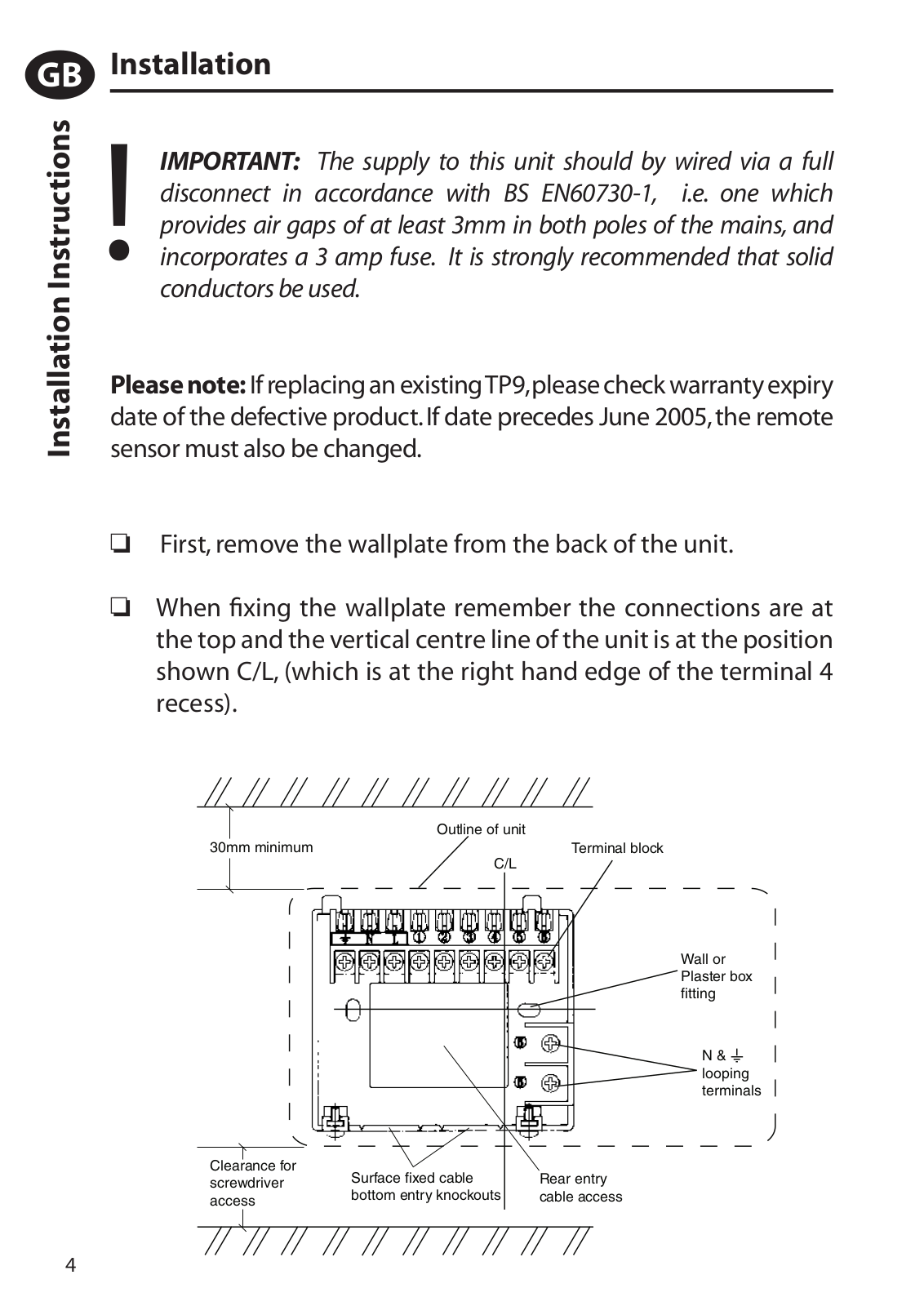
When fixing the wallplate remember the connections are at the top and the vertical centre line of the unit is at the position shown C/L, (which is at the right hand edge of the terminal 4 recess).


Outline of unit

30mm minimum

Terminal block


C/L


Wall or Plaster box fitting

N & looping terminals

Clearance for

Surface fixed cable

Rear entry

screwdriver

bottom entry knockouts

cable access

access


4

Fix the wallplate to the wall or flush mounted box as required. Surface cables can only enter from below the unit. If mounted on a flush mounted box, cables can enter from the rear through the aperture in the wallplate.

Whilst the unit does not require an Earth connection, two terminals are provided on the wallplate for Earth continuity purposes.

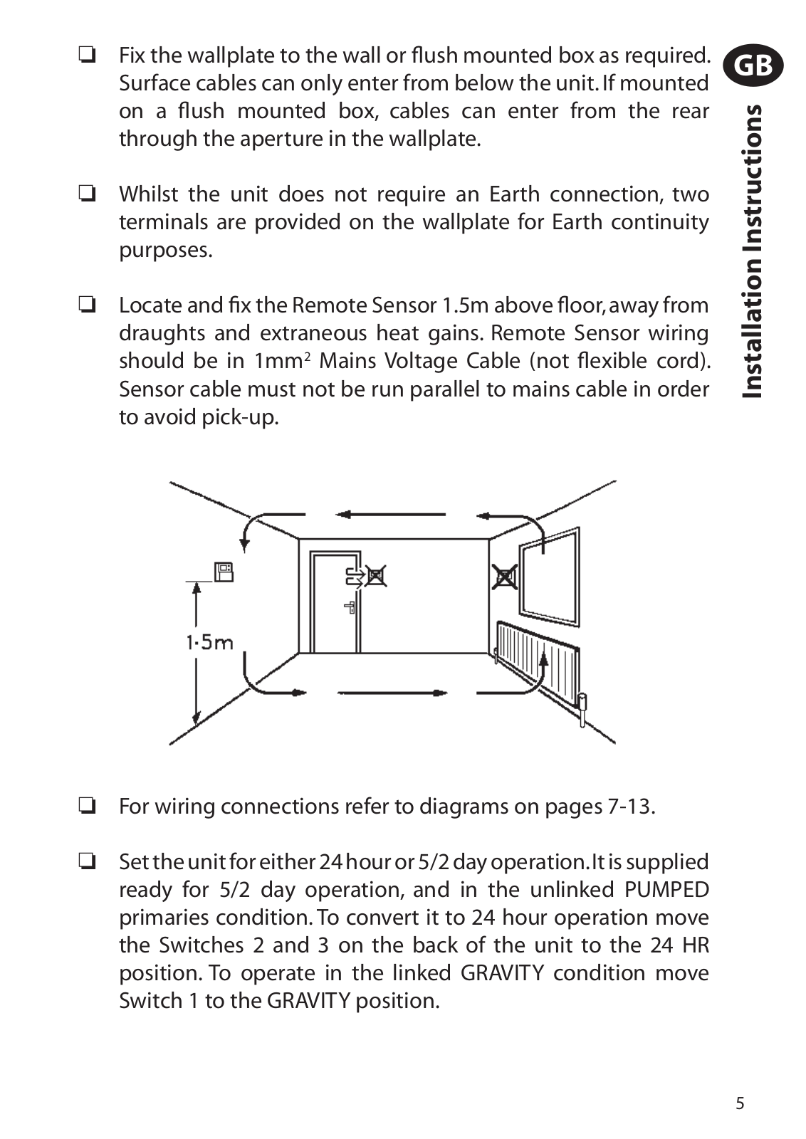
Locate and fix the Remote Sensor 1.5m above floor, away from draughts and extraneous heat gains. Remote Sensor wiring should be in 1mm2 Mains Voltage Cable (not flexible cord). Sensor cable must not be run parallel to mains cable in order to avoid pick-up.

For wiring connections refer to diagrams on pages 7-13.

Set the unit for either 24 hour or 5/2 day operation.It is supplied ready for 5/2 day operation, and in the unlinked PUMPED primaries condition. To convert it to 24 hour operation move the Switches 2 and 3 on the back of the unit to the 24 HR position. To operate in the linked GRAVITY condition move Switch 1 to the GRAVITY position.

GB

<![if ! IE]>

<![endif]>Installation Instructions

5

GB

<![if ! IE]>

<![endif]>Installation Instructions

The operating temperature range, which is factory preset to 5- 30°C,can also be reset at time of installation to 16-30°C making the TP9 a safe solution for use in sheltered accommodation (where hypothermia may be of concern, for example). To alter the factory preset, move Switch 4 on the back of the unit.

Locate the module on the two locating lugs on the top of the wallplate and hinge downwards to fully engage the fixing screws in the slots at the bottom of the module. Tighten the screws.

!Important: To remove unit from wall, isolate power supply. Slacken the two screws at the underside of the module and ease the bottom of the module away from the wall to disengage from the wallplate.Lift the module off the two locating lugs on the top of the wallplate.

6

Wiring

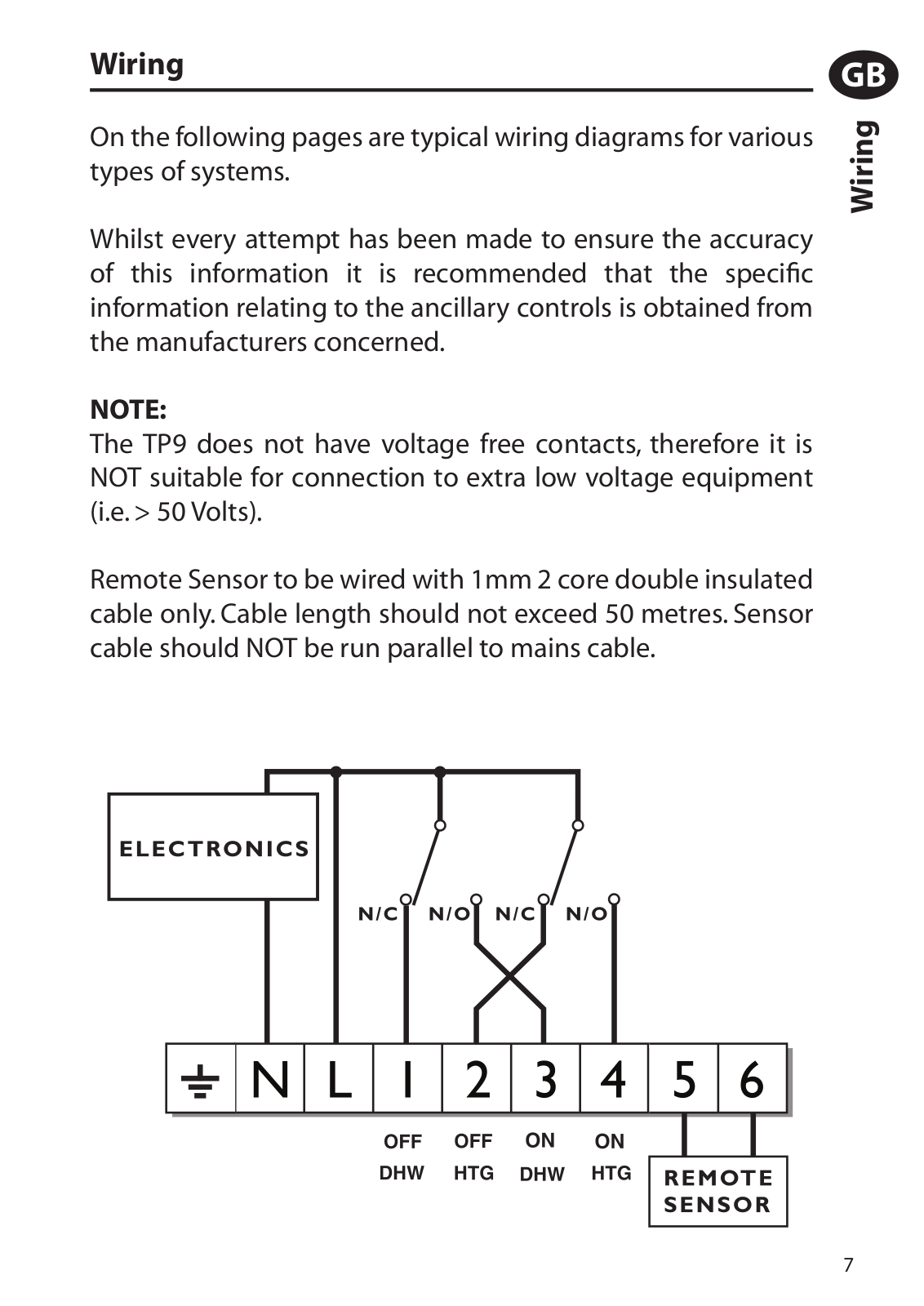
On the following pages are typical wiring diagrams for various types of systems.

Whilst every attempt has been made to ensure the accuracy of this information it is recommended that the specific information relating to the ancillary controls is obtained from the manufacturers concerned.

NOTE:

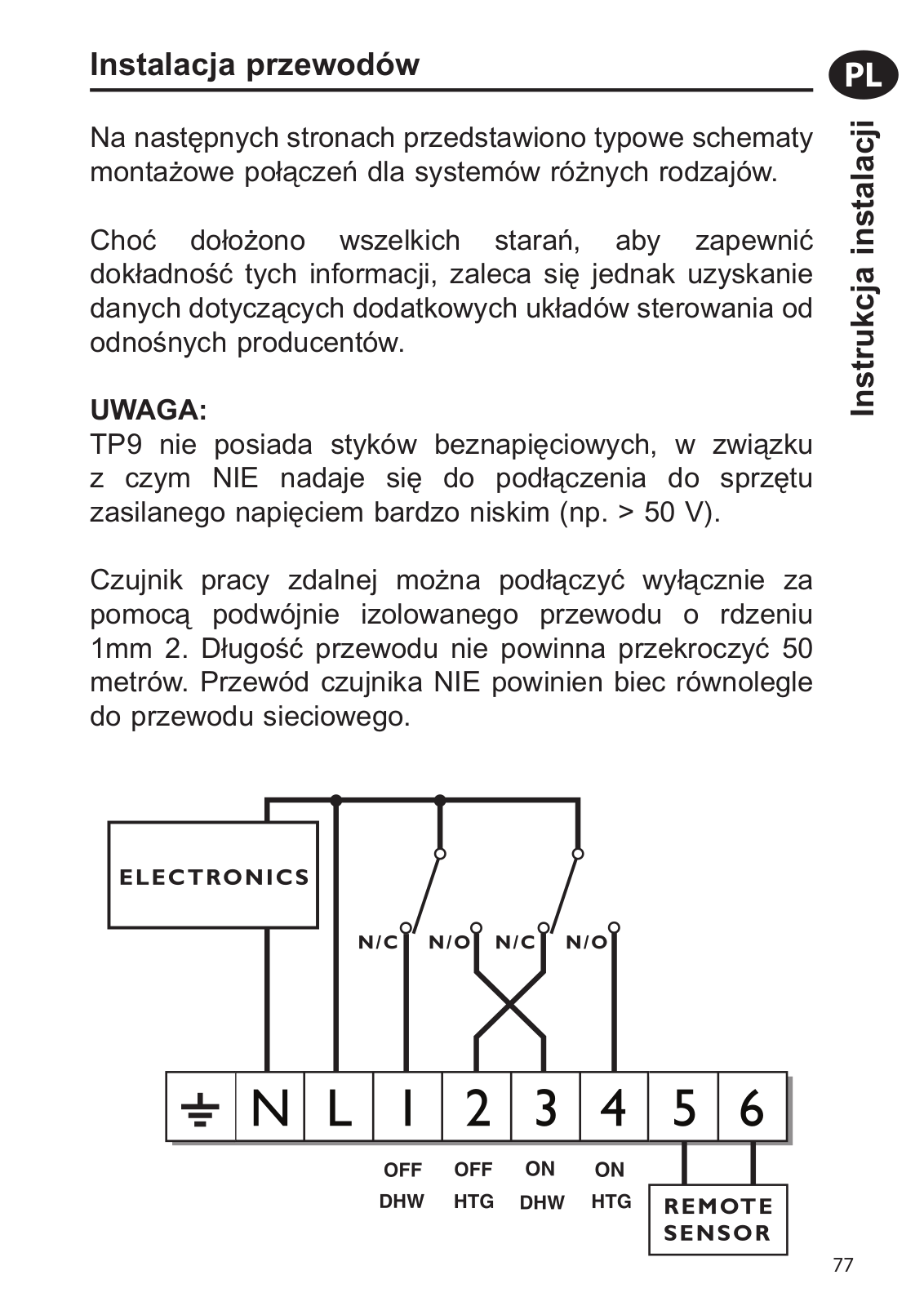
The TP9 does not have voltage free contacts, therefore it is NOT suitable for connection to extra low voltage equipment (i.e. > 50 Volts).

Remote Sensor to be wired with 1mm 2 core double insulated cable only. Cable length should not exceed 50 metres. Sensor cable should NOT be run parallel to mains cable.

GB

<![if ! IE]>

<![endif]>Wiring

7

GB

<![if ! IE]>

<![endif]>Wiring

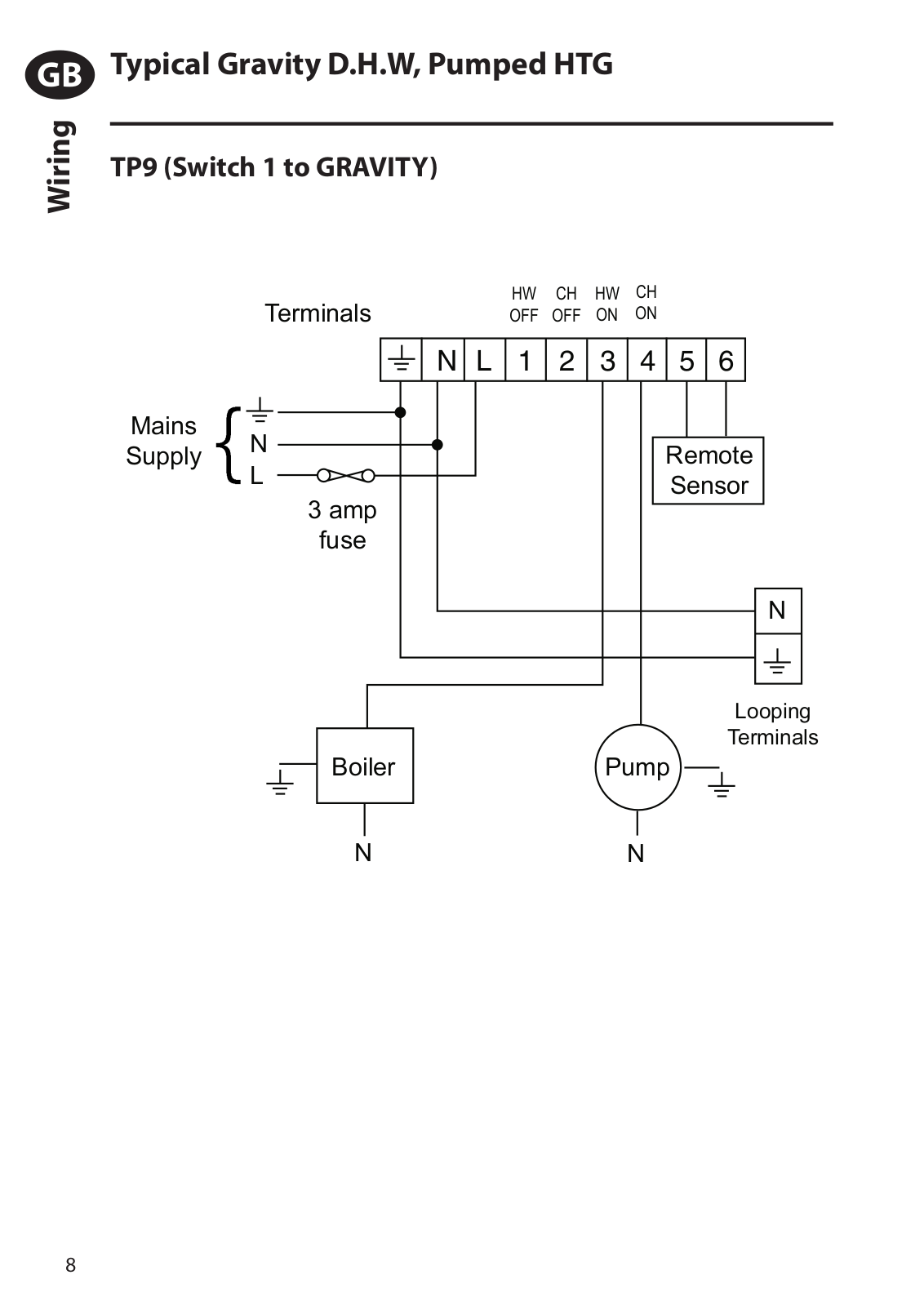
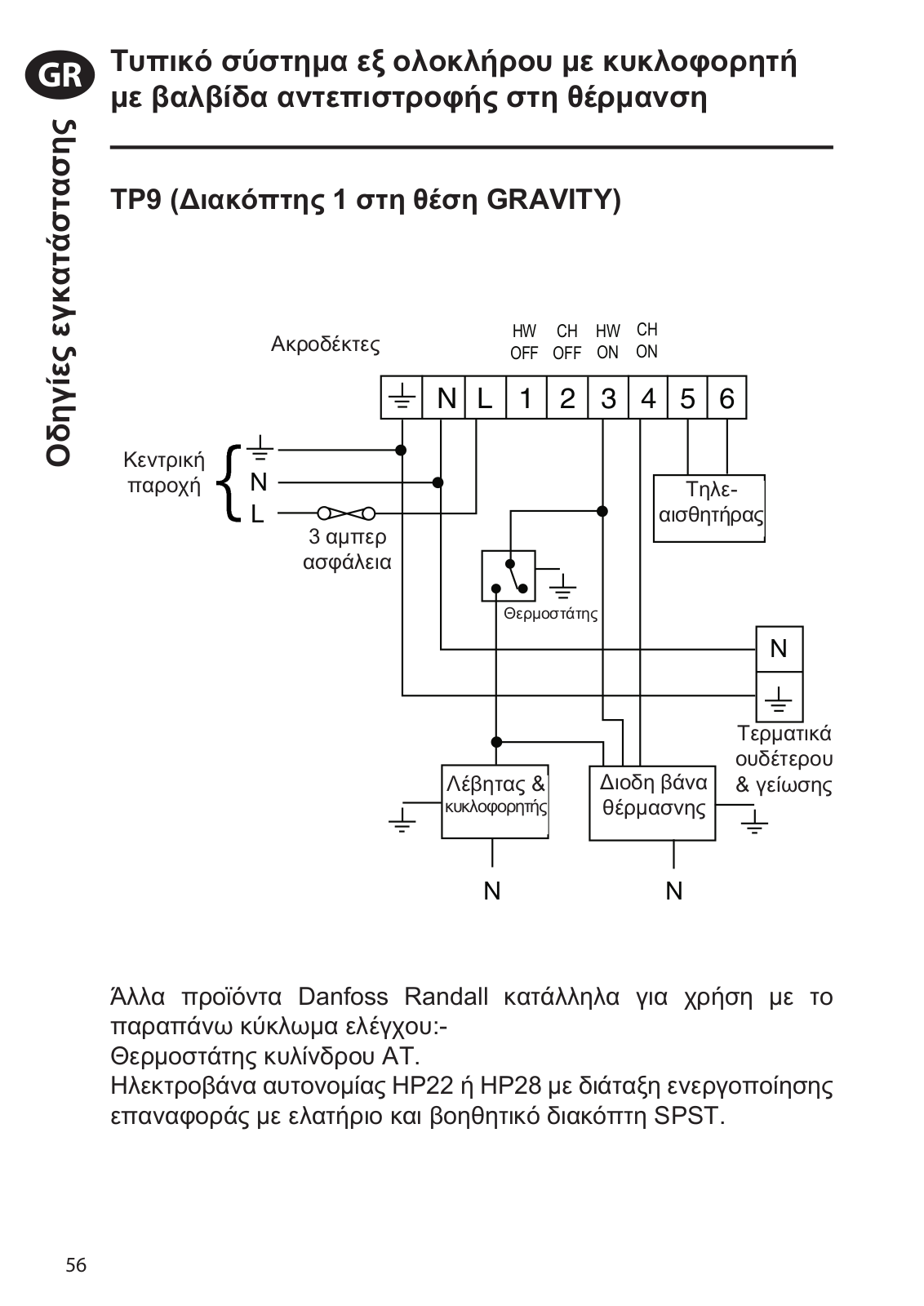
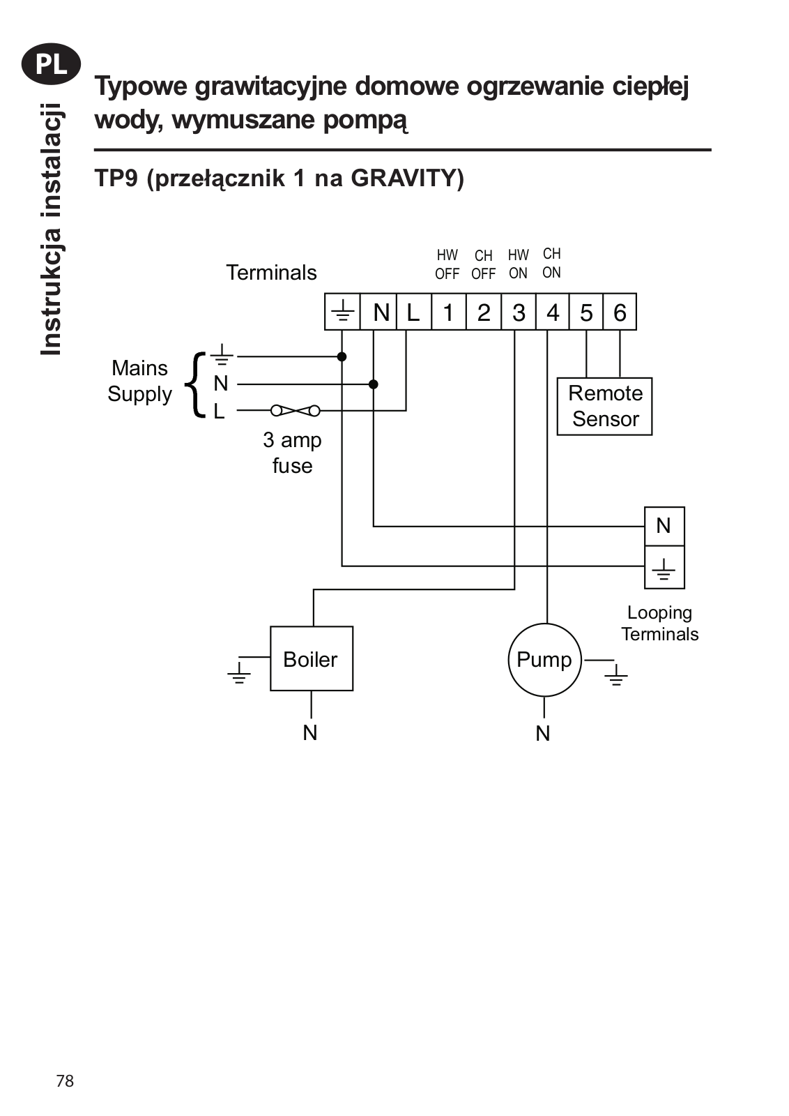
Typical Gravity D.H.W, Pumped HTG

TP9 (Switch 1 to GRAVITY)


N

L

1

2

3

4

5

6


8

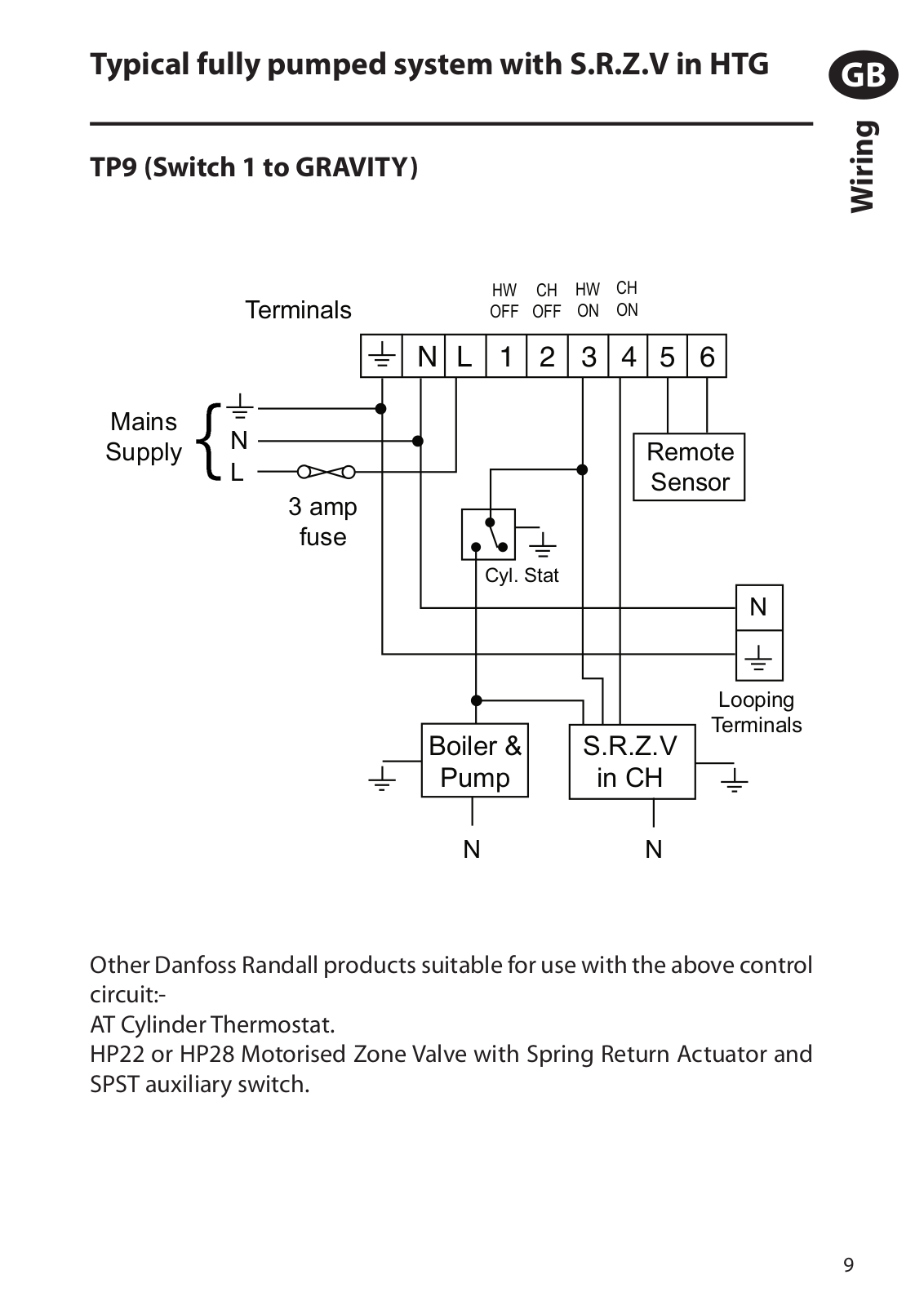
Typical fully pumped system with S.R.Z.V in HTG

TP9 (Switch 1 to GRAVITY)


N

L

1 2 3 4 5 6


GB

<![if ! IE]>

<![endif]>Wiring

Other Danfoss Randall products suitable for use with the above control circuit:-

AT Cylinder Thermostat.

HP22 or HP28 Motorised Zone Valve with Spring Return Actuator and SPST auxiliary switch.

9

GB

<![if ! IE]>

<![endif]>Wiring

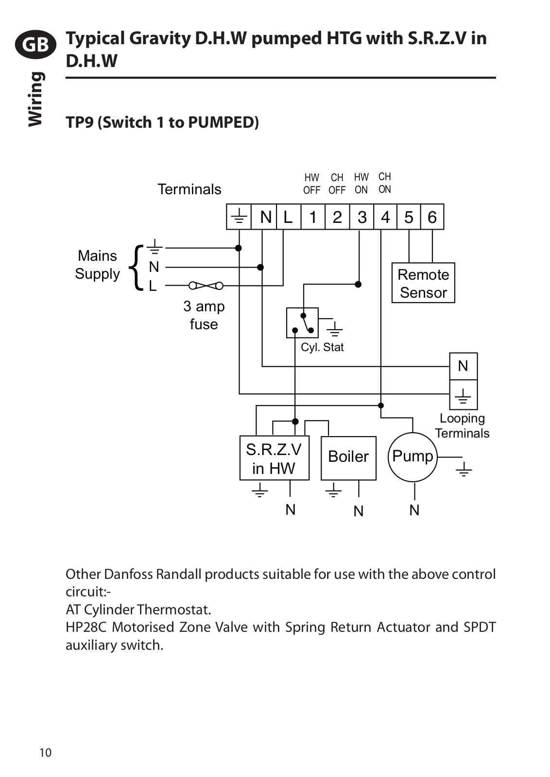
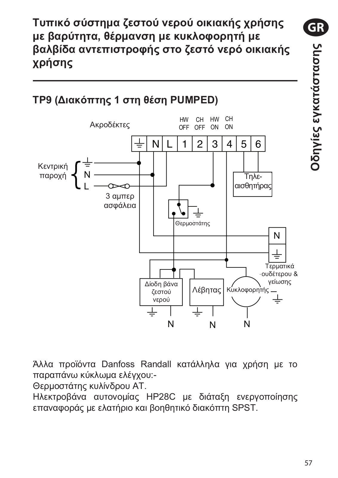
Typical Gravity D.H.W pumped HTG with S.R.Z.V in D.H.W

TP9 (Switch 1 to PUMPED)


Terminals


N L

1 2 3 4 5 6

Mains

N


Supply


Remote

L


Sensor


3 amp


fuse


Cyl. Stat


N


Looping


S.R.Z.V


Terminals


Boiler

Pump


in HW


N


N

N

Other Danfoss Randall products suitable for use with the above control circuit:-

AT Cylinder Thermostat.

HP28C Motorised Zone Valve with Spring Return Actuator and SPDT auxiliary switch.

10

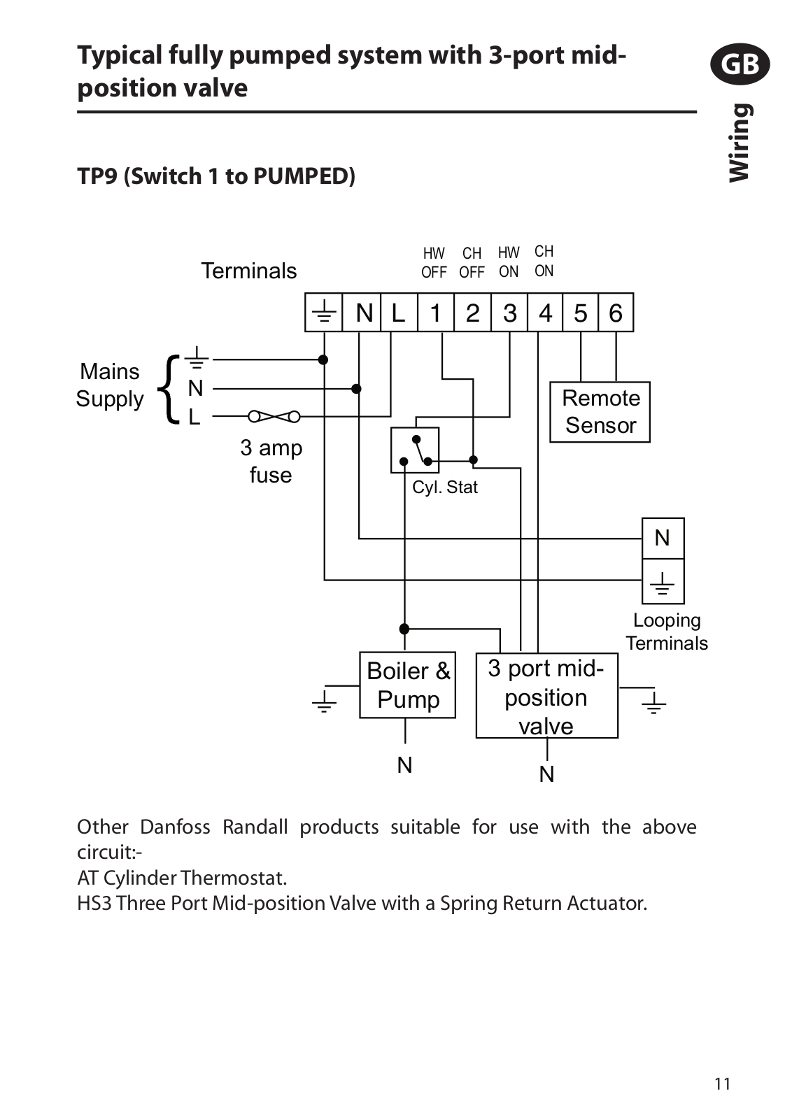
Typical fully pumped system with 3-port midposition valve

TP9 (Switch 1 to PUMPED)

GB

<![if ! IE]>

<![endif]>Wiring


Terminals


N

L

1 2 3 4 5 6

Mains

N


Supply


Remote

L


Sensor


3 amp


fuse


Cyl. Stat


N

Looping

Terminals

Boiler &

3 port mid-

Pump

position

valve

N N

Other Danfoss Randall products suitable for use with the above circuit:-

AT Cylinder Thermostat.

HS3 Three Port Mid-position Valve with a Spring Return Actuator.

11

GB

<![if ! IE]>

<![endif]>Wiring

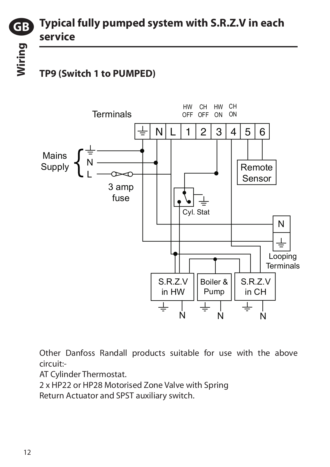
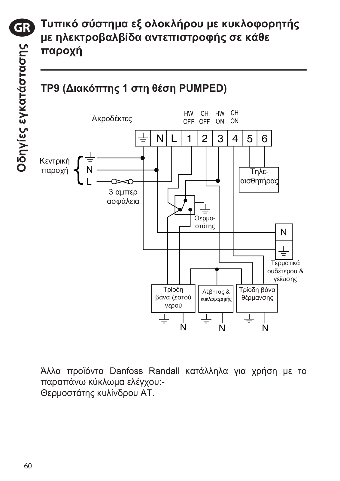
Typical fully pumped system with S.R.Z.V in each service

TP9 (Switch 1 to PUMPED)


Terminals


N L

1 2 3 4 5 6

Mains

N


Supply


Remote

L


Sensor


3 amp


fuse


Cyl. Stat


N


Looping


Terminals


S.R.Z.V

Boiler &

S.R.Z.V


in HW

Pump

in CH


N


N

N

Other Danfoss Randall products suitable for use with the above circuit:-

AT Cylinder Thermostat.

2 x HP22 or HP28 Motorised Zone Valve with Spring Return Actuator and SPST auxiliary switch.

12

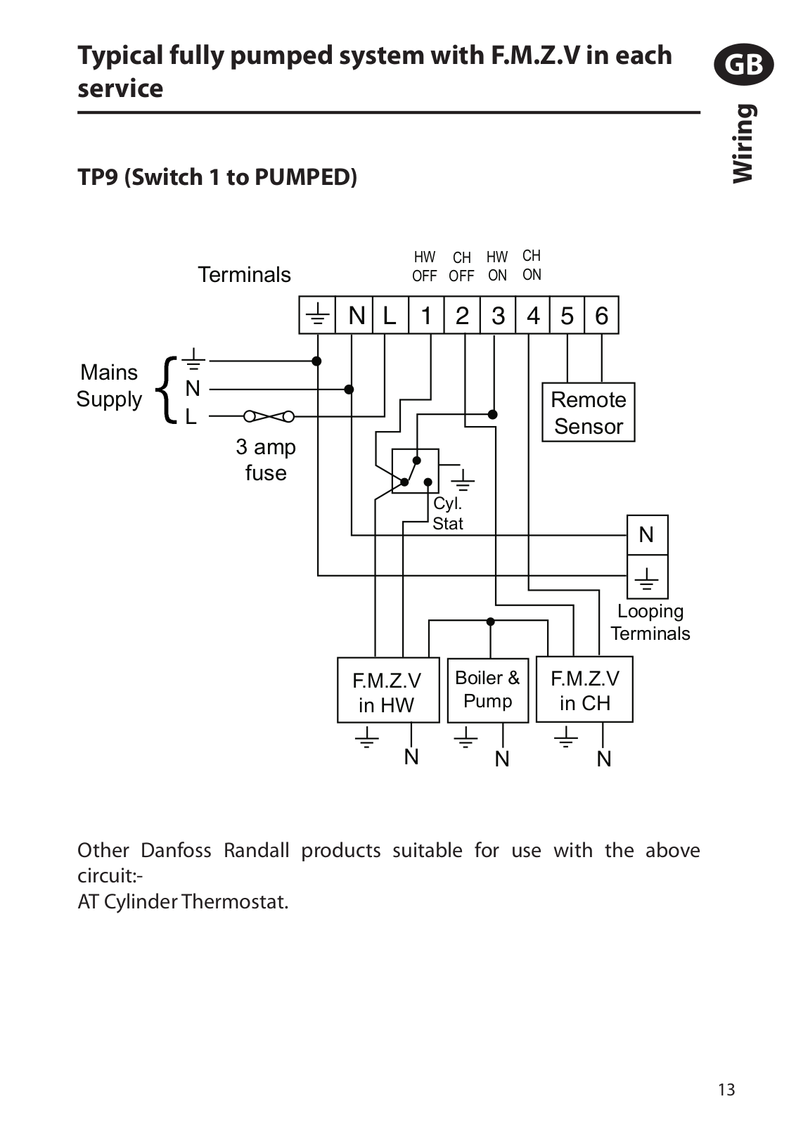
Typical fully pumped system with F.M.Z.V in each service

TP9 (Switch 1 to PUMPED)


Terminals


N L

1 2 3 4 5 6

Mains

N


Supply


Remote

L


Sensor


3 amp


fuse


Cyl.


Stat


N


Looping


Terminals


F.M.Z.V

Boiler &

F.M.Z.V


in HW

Pump

in CH


N


N

N

GB

<![if ! IE]>

<![endif]>Wiring

Other Danfoss Randall products suitable for use with the above circuit:-

AT Cylinder Thermostat.

13

Danfoss TP9 User guide

GB

<![if ! IE]>

<![endif]>User Instructions

What is a programmable room thermostat?

... an explanation for householders.

A programmable room thermostat is both a programmer and a room thermostat. A programmer allows you to set ‘On’ and ‘Off’ time periods to suit your own lifestyle. A room thermostat works by sensing the air temperature, switching on the heating when the air temperature falls below the thermostat setting, and switching it off once this set temperature has been reached.

So, a programmable room thermostat lets you choose what times you want the heating to be on,and what temperature it should reach while it is on.It will allow you to select different temperatures in your home at different times of the day (and days of the week) to meet your particular needs.

Turning a programmable room thermostat to a higher setting will not make the room heat up any faster.How quickly the room heats up depends on the design of the heating system, for example, the size of boiler and radiators.

Neither does the setting affect how quickly the room cools down.Turning a programmable room thermostat to a lower setting will result in the room being controlled at a lower temperature, and saves energy.

The way to set and use your programmable room thermostat is to find the lowest temperature settings that you are comfortable with at the different times you have chosen, and then leave it alone to do its job.The best way to do this is to set low temperatures first, say 18°C, and then turn them up by one degree each day until you are comfortable with the temperatures.You won’t have to adjust the thermostat further. Any adjustments above these settings will waste energy and cost you more money.

If your heating system is a boiler with radiators,there will usually be only one programmable room thermostat to control the whole house. But you can have different temperatures in individual rooms by installing thermostatic radiator valves (TRVs) on individual radiators. If you don’t have TRVs, you should choose a temperature that is reasonable for the whole ho use. If you do have TRVs, you can choose a slightly higher setting to make sure that even the coldest room is comfortable, then prevent any overheating in other rooms by adjusting the TRVs.

The time on the programmer must be correct.Some types have to be adjusted in spring and autumn at the changes between Greenwich Mean Time and British Summer Time.

You may be able to temporarily adjust the heating programme, for example, ‘Override’, ‘Advance’or‘Boost’.These are explained in the manufacturer’s instructions.

Programmable room thermostats need a free flow of air to sense the temperature, so they must not be covered by curtains or blocked by furniture. Nearby electric fires, televisions, wall or table lamps may prevent the thermostat from working properly.

Please note: The TP9 also incorporates a timeswitch for domestic hot water control.

14

User Instructions

Your programmable thermostat

The TP9 is a programmable thermostat designed to control both your hot water and heating.You can programme up to 6 different time and temperature settings per day for the heating, and the hot water can be turned on and off twice a day.

The TP9 will control your heating and hot water together or independently (i.e. hot water only during the summer, heating only for frost protection when building is empty). It also features 2 temporary user overrides for added convenience.

GB

<![if ! IE]>

<![endif]>User Instructions

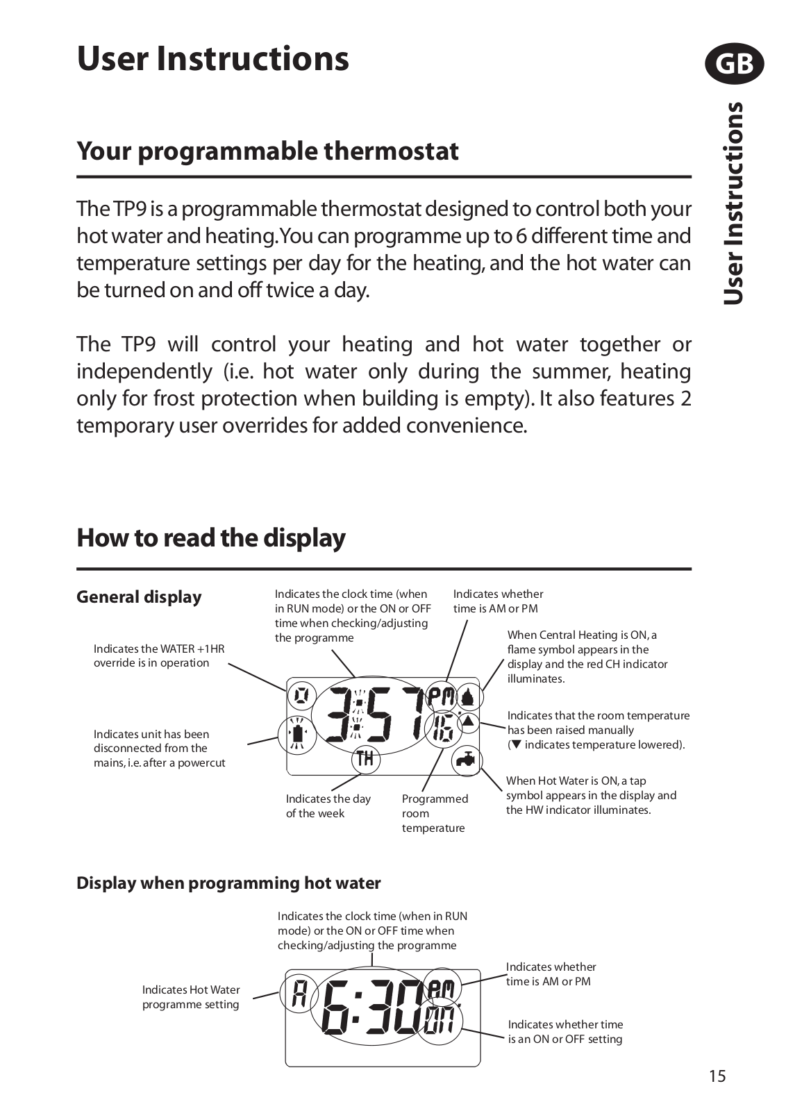
How to read the display

General display

Indicates the WATER +1HR override is in operation

Indicates unit has been disconnected from the mains, i.e. after a powercut

Indicates the clock time (when

Indicates whether

in RUN mode) or the ON or OFF

time is AM or PM

time when checking/adjusting


When Central Heating is ON, a

the programme


flame symbol appears in the


display and the red CH indicator


illuminates.


Indicates that the room temperature


has been raised manually


( indicates temperature lowered).


When Hot Water is ON, a tap

Indicates the day

Programmed

symbol appears in the display and

the HW indicator illuminates.

of the week

room


temperature

Display when programming hot water

Indicates the clock time (when in RUN mode) or the ON or OFF time when checking/adjusting the programme

Indicates whether

time is AM or PM

Indicates Hot Water programme setting

Indicates whether time is an ON or OFF setting

15

GB

<![if ! IE]>

<![endif]>User Instructions

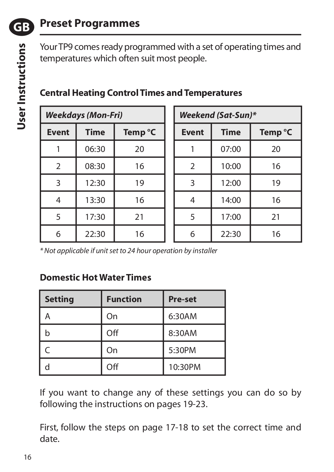
Preset Programmes

Your TP9 comes ready programmed with a set of operating times and temperatures which often suit most people.

Central Heating Control Times and Temperatures

Weekdays (Mon-Fri)

Event

Time

Temp °C


1

06:30

20


2

08:30

16


3

12:30

19


4

13:30

16


5

17:30

21


6

22:30

16


Weekend (Sat-Sun)*

Event

Time

Temp °C


1

07:00

20


2

10:00

16


3

12:00

19


4

14:00

16


5

17:00

21


6

22:30

16


* Not applicable if unit set to 24 hour operation by installer

Domestic Hot Water Times

Setting

Function

Pre-set


A

On

6:30AM


b

Off

8:30AM


C

On

5:30PM


d

Off

10:30PM


If you want to change any of these settings you can do so by following the instructions on pages 19-23.

First, follow the steps on page 17-18 to set the correct time and date.

16

Before you start

First time installation only

When the unit is first removed from its packaging the display will, most probably, just show two dots (the colon). This is not a fault, but a battery saving feature.

Once fitted in accordance with the Installation Instructions supplied and the mains electricity is switched on, the unit should be activated by pressing any button and then RESET.

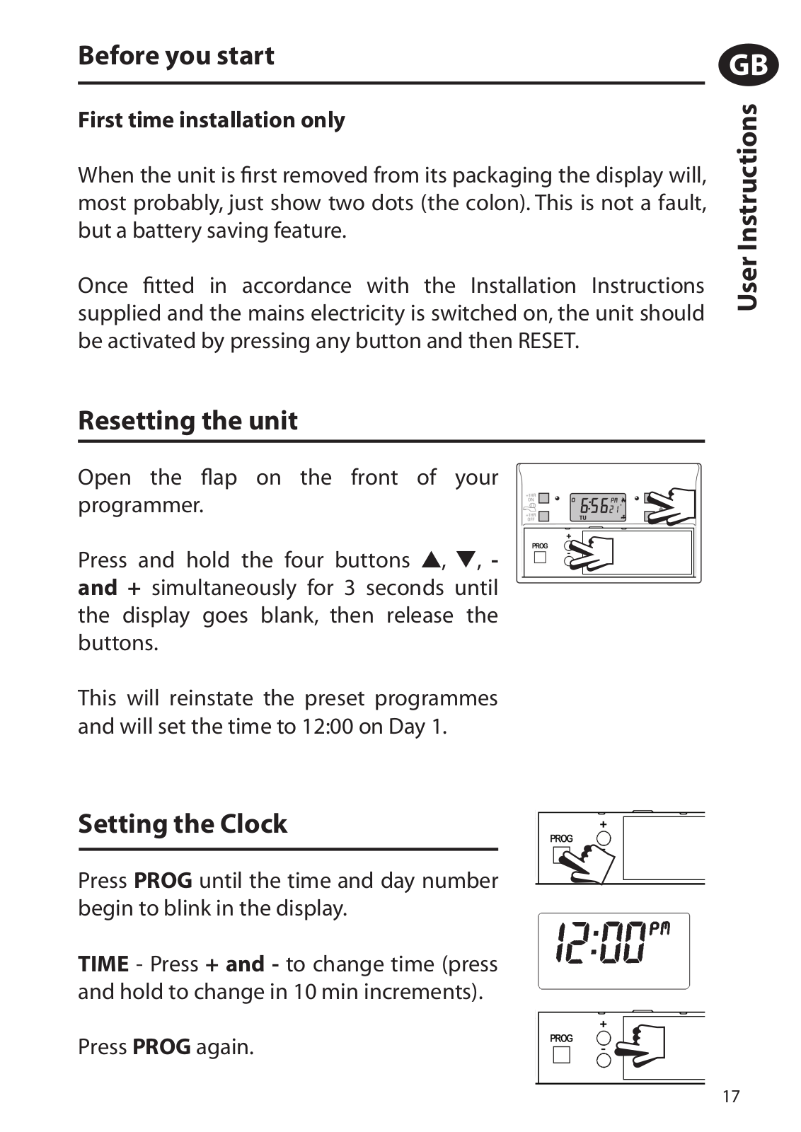
Resetting the unit

Open the flap on the front of your programmer.

Press and hold the four buttons , , - and + simultaneously for 3 seconds until the display goes blank, then release the buttons.

This will reinstate the preset programmes and will set the time to 12:00 on Day 1.

GB

<![if ! IE]>

<![endif]>User Instructions

Setting the Clock

Press PROG until the time and day number begin to blink in the display.

TIME - Press + and - to change time (press and hold to change in 10 min increments).

Press PROG again.

17

GB

<![if ! IE]>

<![endif]>User Instructions

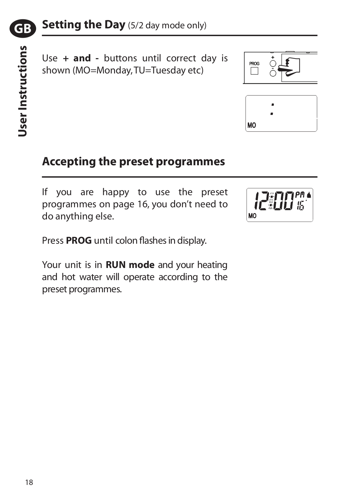
Setting the Day (5/2 day mode only)

Use + and - buttons until correct day is shown (MO=Monday, TU=Tuesday etc)

Accepting the preset programmes

If you are happy to use the preset programmes on page 16, you don’t need to do anything else.

Press PROG until colon flashes in display.

Your unit is in RUN mode and your heating and hot water will operate according to the preset programmes.

18

Before you change the preset programme

Your installer will have set your unit to operate in either 24 hour mode or 5/2 day mode.

To tell which mode your unit is set press PROG until Event 1 flashes in the display.

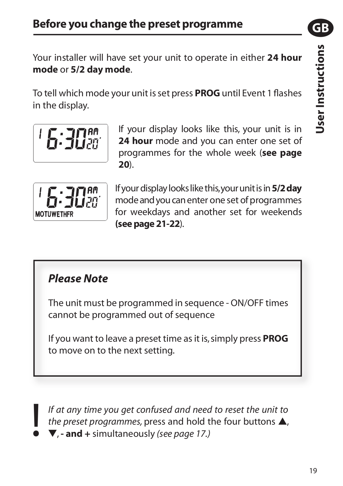
If your display looks like this, your unit is in 24 hour mode and you can enter one set of programmes for the whole week (see page 20).

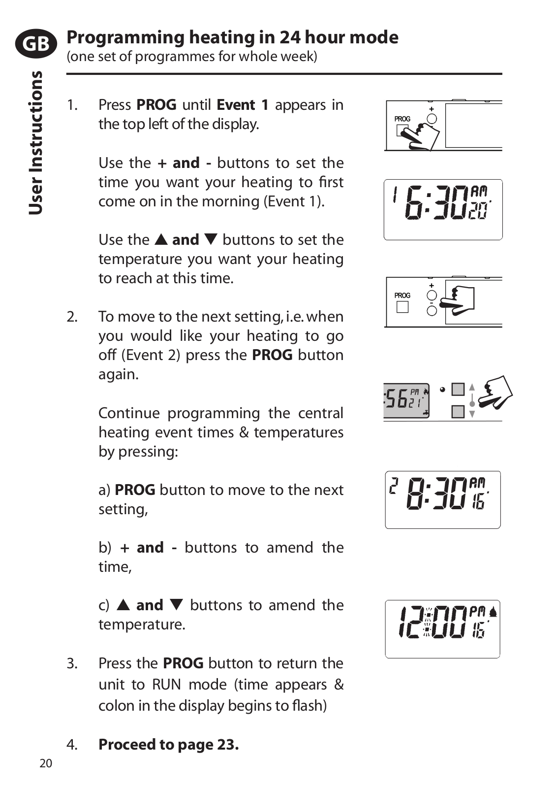
If your display looks like this,your unit is in 5/2day mode and you can enter one set of programmes for weekdays and another set for weekends

(see page 21-22).

GB

<![if ! IE]>

<![endif]>User Instructions

! If at any time you get confused and need to reset the unit to the preset programmes, press and hold the four buttons ,

, - and + simultaneously (see page 17.)

19

GB

<![if ! IE]>

<![endif]>User Instructions

Programming heating in 24 hour mode

(one set of programmes for whole week)

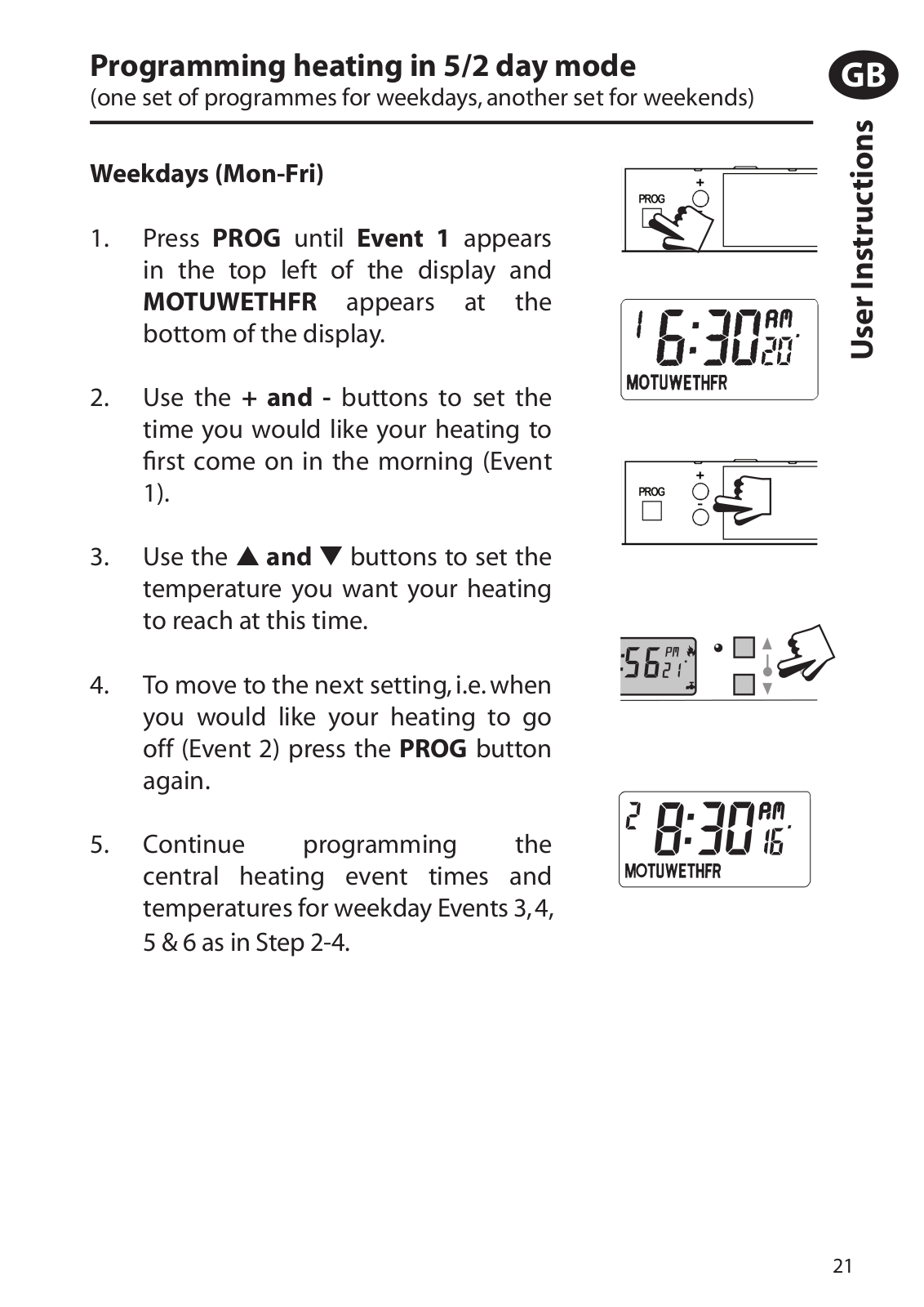
1.Press PROG until Event 1 appears in

the top left of the display.

Use the + and - buttons to set the time you want your heating to first come on in the morning (Event 1).

Use the and buttons to set the temperature you want your heating to reach at this time.

2. To move to the next setting, i.e. when you would like your heating to go off (Event 2) press the PROG button again.

Continue programming the central heating event times & temperatures by pressing:

a)PROG button to move to the next setting,

b)+ and - buttons to amend the time,

c)and buttons to amend the temperature.

3.Press the PROG button to return the unit to RUN mode (time appears & colon in the display begins to flash)

4.Proceed to page 23.

20

Programming heating in 5/2 day mode

(one set of programmes for weekdays, another set for weekends)

Weekdays (Mon-Fri)

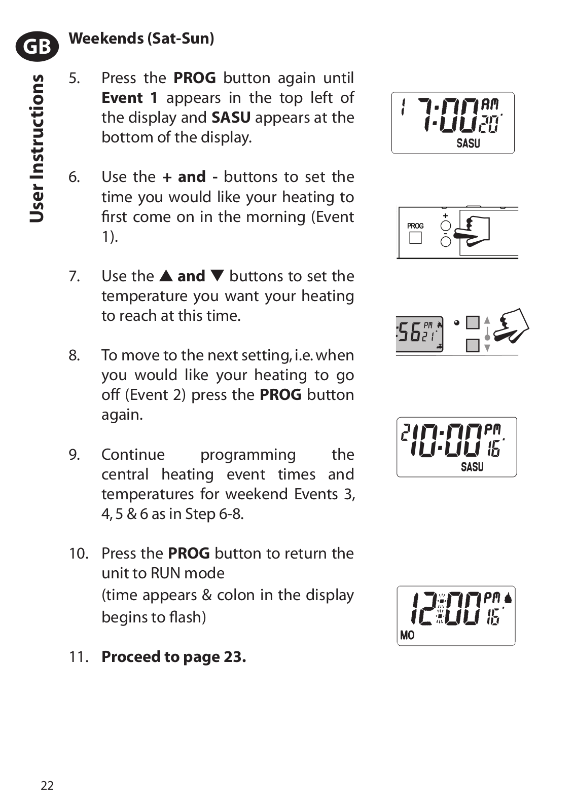
1. Press PROG until Event 1 appears in the top left of the display and MOTUWETHFR appears at the bottom of the display.

2.Use the + and - buttons to set the time you would like your heating to first come on in the morning (Event

1).

3. Use the and buttons to set the temperature you want your heating to reach at this time.

4.To move to the next setting, i.e. when you would like your heating to go off (Event 2) press the PROG button again.

5. Continue programming the central heating event times and temperatures for weekday Events 3, 4, 5 & 6 as in Step 2-4.

GB

<![if ! IE]>

<![endif]>User Instructions

21

GB

<![if ! IE]>

<![endif]>User Instructions

Weekends (Sat-Sun)

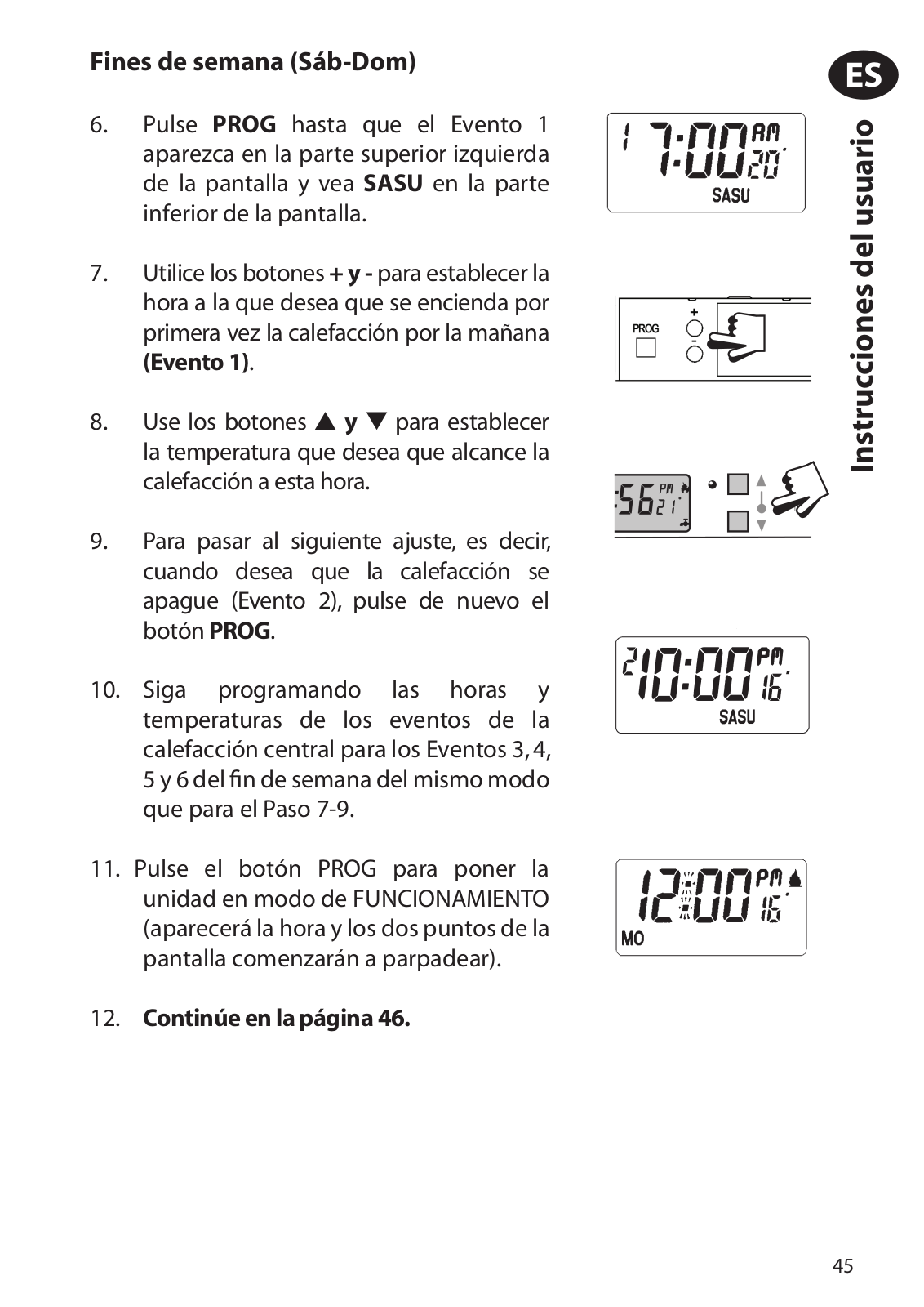
5.Press the PROG button again until Event 1 appears in the top left of the display and SASU appears at the bottom of the display.

6.Use the + and - buttons to set the time you would like your heating to first come on in the morning (Event 1).

7. Use the and buttons to set the temperature you want your heating to reach at this time.

8.To move to the next setting, i.e. when you would like your heating to go off (Event 2) press the PROG button again.

9. Continue programming the central heating event times and temperatures for weekend Events 3, 4, 5 & 6 as in Step 6-8.

10.Press the PROG button to return the unit to RUN mode

(time appears & colon in the display begins to flash)

11.Proceed to page 23.

22

Programming the Hot Water

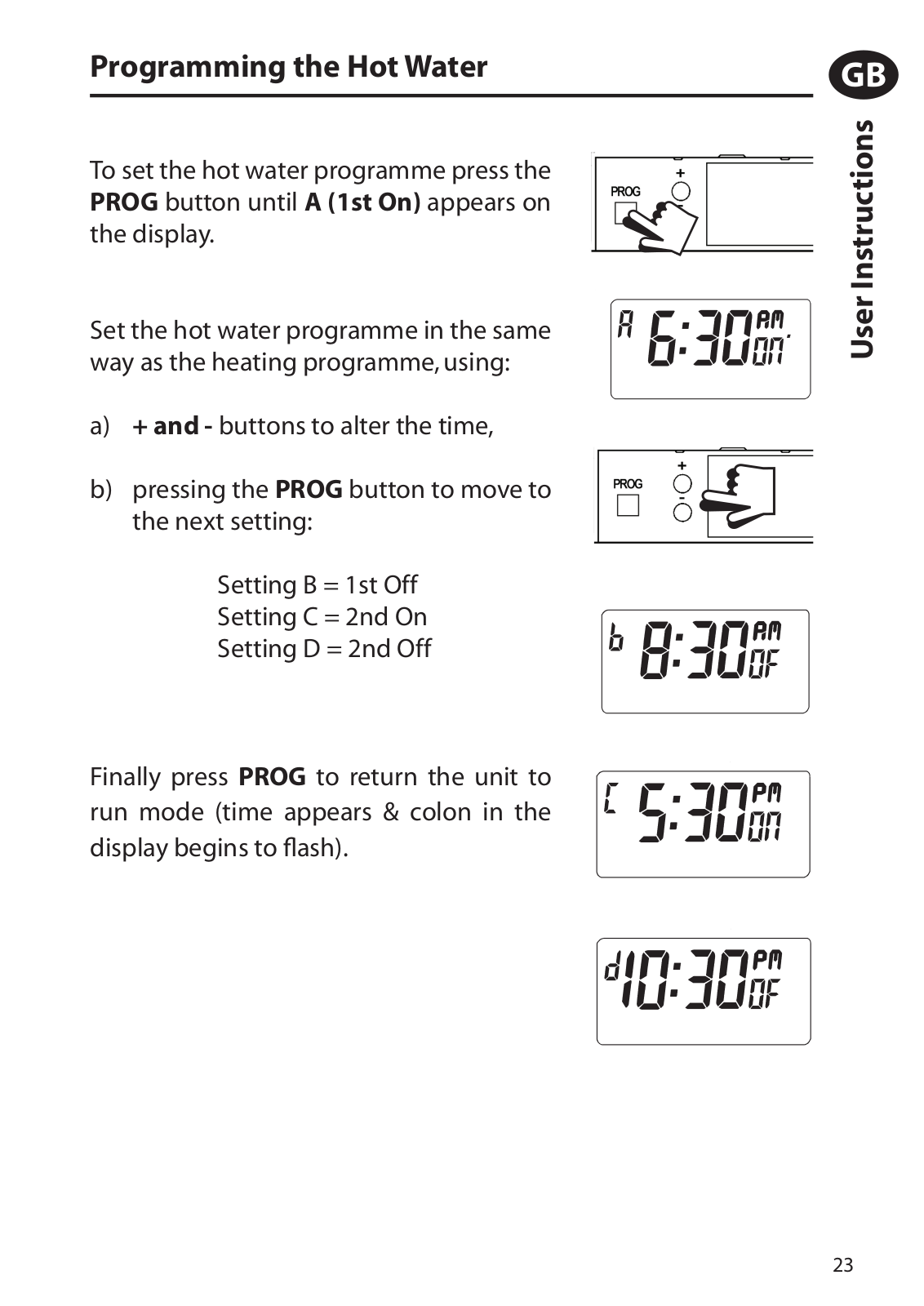
To set the hot water programme press the PROG button until A (1st On) appears on the display.

Set the hot water programme in the same way as the heating programme, using:

a)+ and - buttons to alter the time,

b)pressing the PROG button to move to the next setting:

Setting B = 1st Off

Setting C = 2nd On

Setting D = 2nd Off

Finally press PROG to return the unit to run mode (time appears & colon in the display begins to flash).

GB

<![if ! IE]>

<![endif]>User Instructions

23

GB

<![if ! IE]>

<![endif]>User Instructions

Running your programme

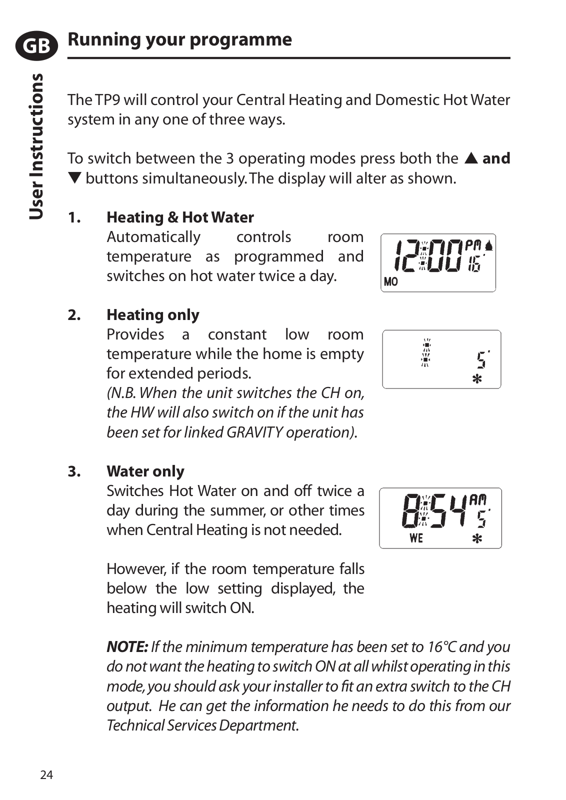
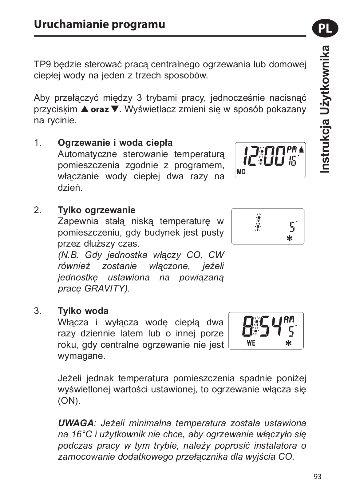
The TP9 will control your Central Heating and Domestic Hot Water system in any one of three ways.

To switch between the 3 operating modes press both the and buttons simultaneously. The display will alter as shown.

1.Heating & Hot Water

Automatically controls room temperature as programmed and switches on hot water twice a day.

2.Heating only

Provides a constant low room temperature while the home is empty for extended periods.

(N.B. When the unit switches the CH on, the HW will also switch on if the unit has been set for linked GRAVITY operation).

3.Water only

Switches Hot Water on and off twice a day during the summer, or other times when Central Heating is not needed.

However, if the room temperature falls below the low setting displayed, the heating will switch ON.

NOTE: If the minimum temperature has been set to 16°C and you do not want the heating to switch ON at all whilst operating in this mode,you should ask your installer to fit an extra switch to the CH output. He can get the information he needs to do this from our Technical Services Department.

24

Temporary User Overrides

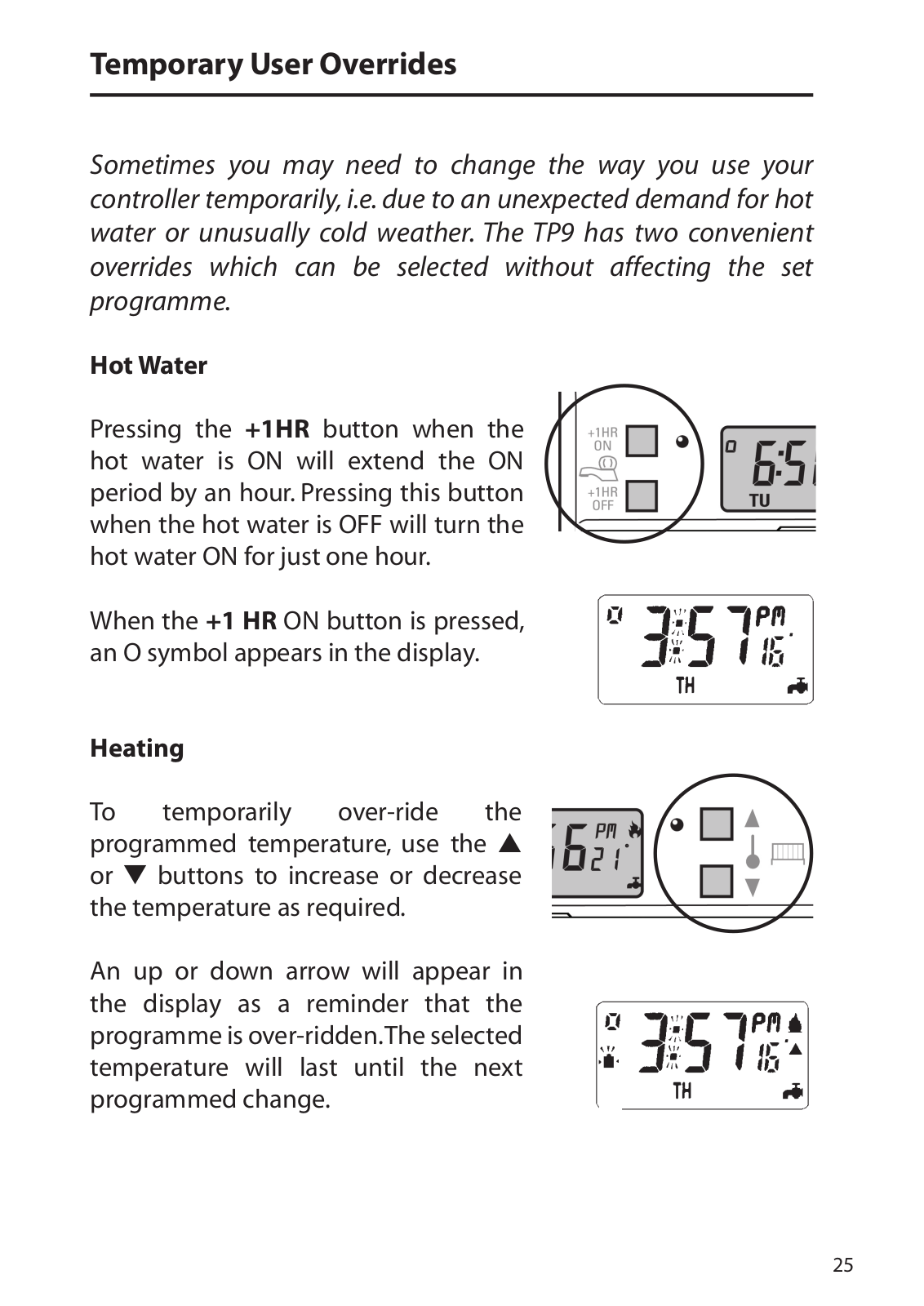
Sometimes you may need to change the way you use your controller temporarily, i.e. due to an unexpected demand for hot water or unusually cold weather. The TP9 has two convenient overrides which can be selected without affecting the set programme.

Hot Water

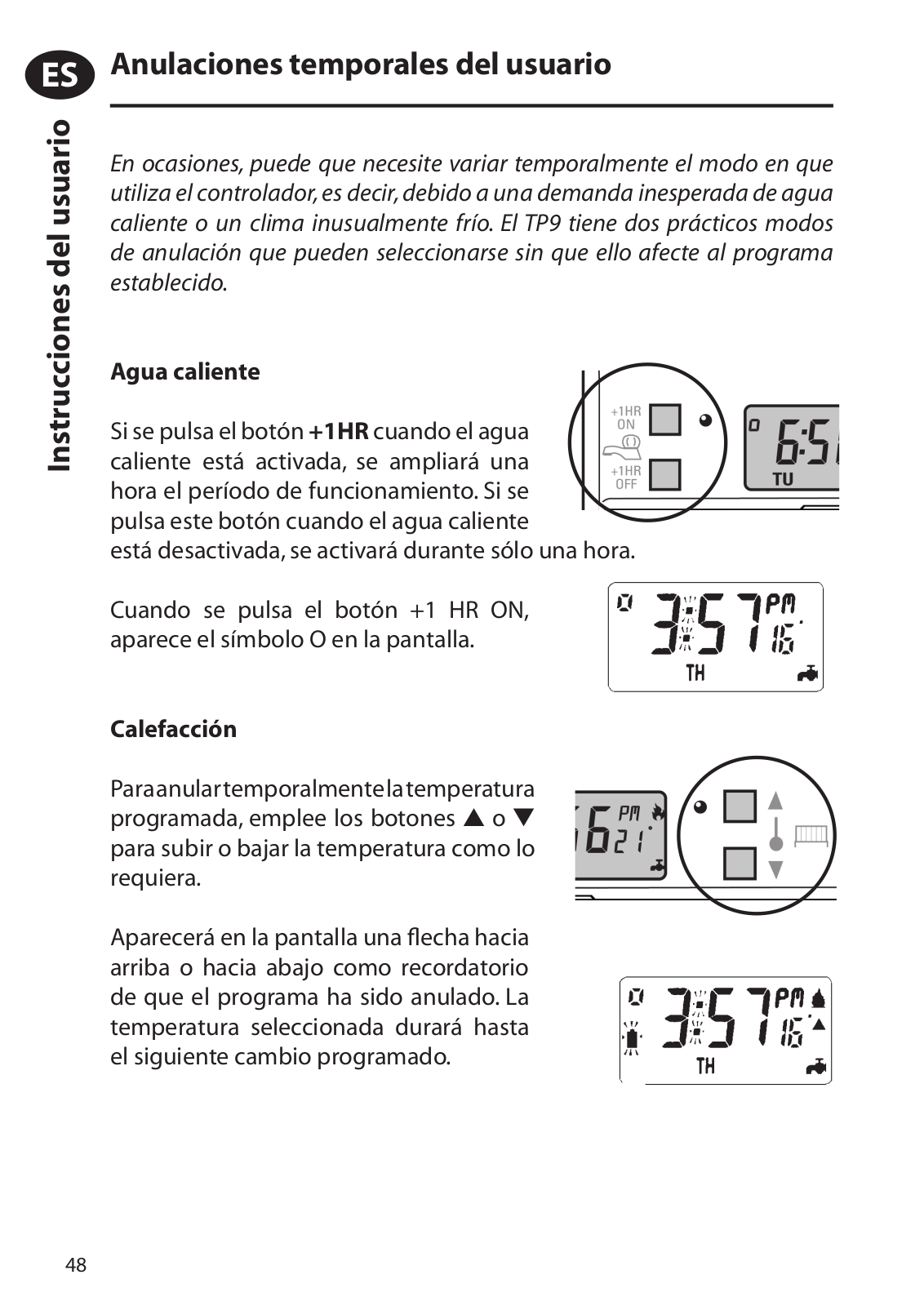
Pressing the +1HR button when the hot water is ON will extend the ON period by an hour. Pressing this button when the hot water is OFF will turn the hot water ON for just one hour.

When the +1 HR ON button is pressed, an O symbol appears in the display.

Heating


To

temporarily

over-ride

the

programmed temperature, use the

or

buttons to increase or decrease

the temperature as required.


An up or down arrow will appear in the display as a reminder that the programme is over-ridden.The selected temperature will last until the next programmed change.

25

GB

<![if ! IE]>

<![endif]>User Instructions

Loss of power

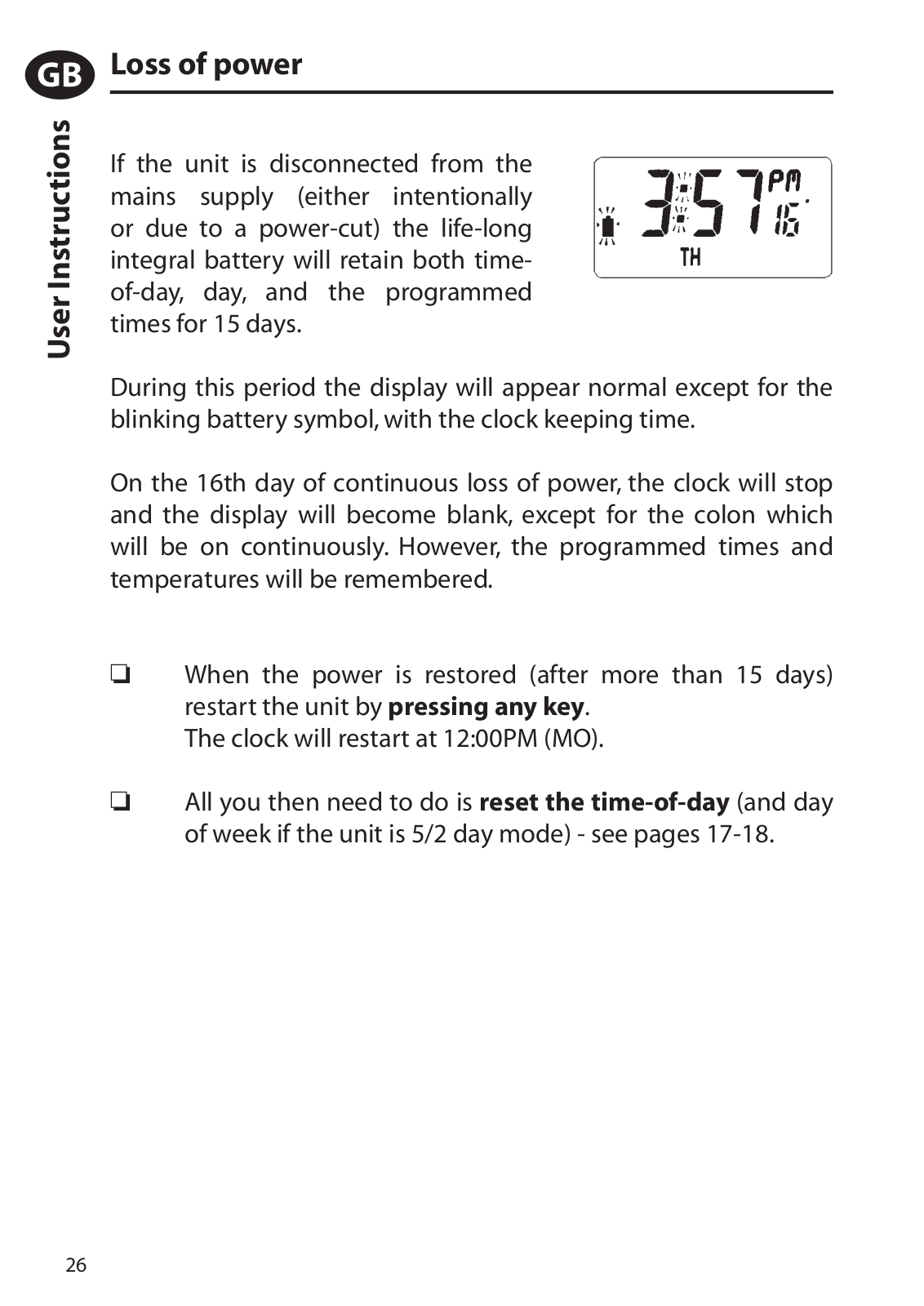
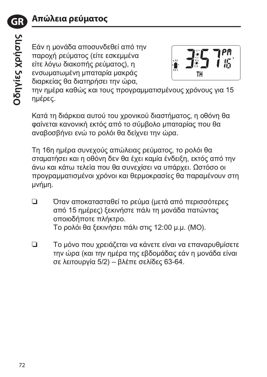
If the unit is disconnected from the mains supply (either intentionally or due to a power-cut) the life-long integral battery will retain both time- of-day, day, and the programmed times for 15 days.

During this period the display will appear normal except for the blinking battery symbol, with the clock keeping time.

On the 16th day of continuous loss of power, the clock will stop and the display will become blank, except for the colon which will be on continuously. However, the programmed times and temperatures will be remembered.

When the power is restored (after more than 15 days) restart the unit by pressing any key.

The clock will restart at 12:00PM (MO).

All you then need to do is reset the time-of-day (and day of week if the unit is 5/2 day mode) - see pages 17-18.

26

Instrucciones de instalación

Observe que:

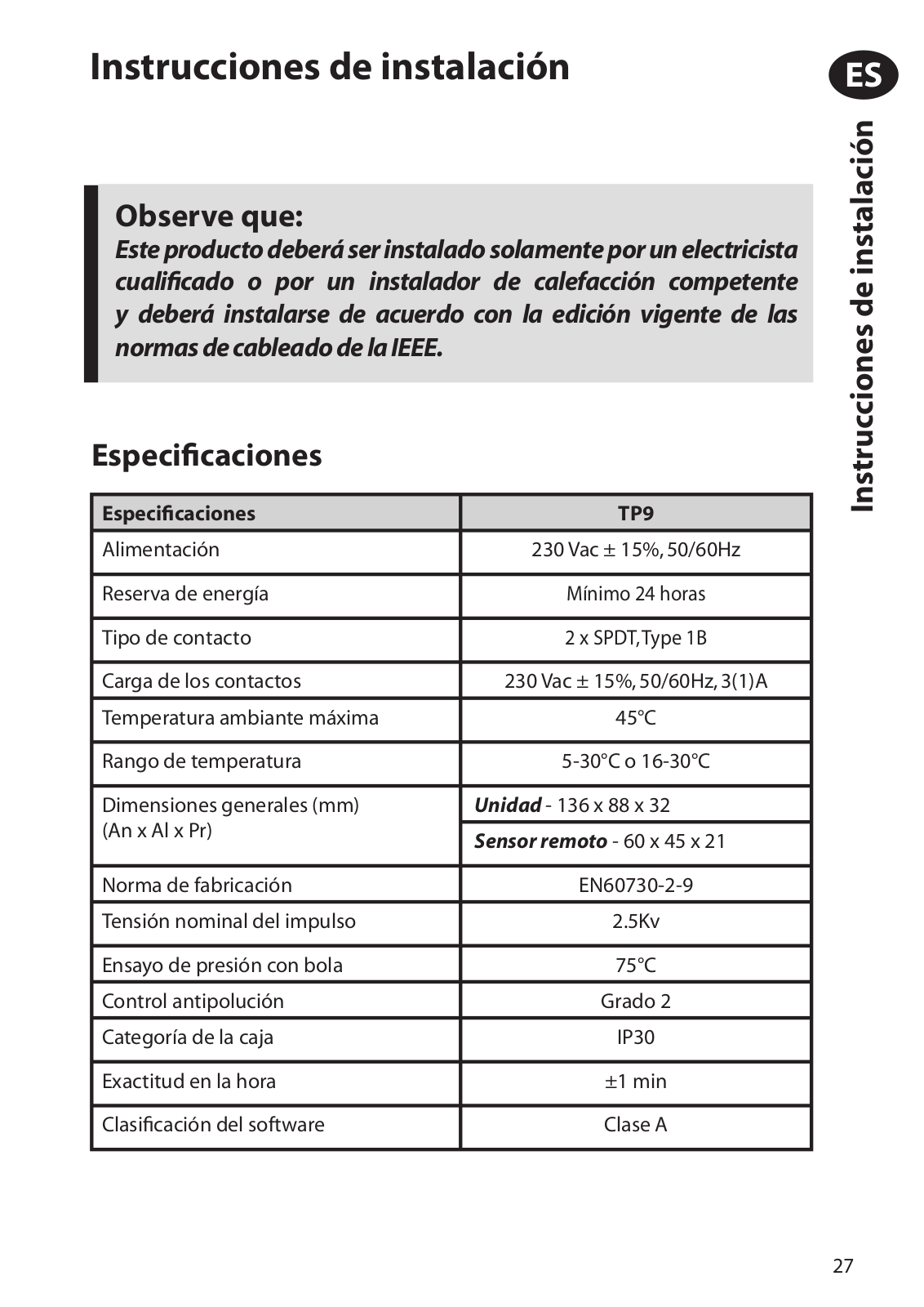
Este producto deberá ser instalado solamente por un electricista cualificado o por un instalador de calefacción competente y deberá instalarse de acuerdo con la edición vigente de las normas de cableado de la IEEE.

Especificaciones

Especificaciones

TP9


Alimentación

230 Vac ± 15%, 50/60Hz


Reserva de energía

Mínimo 24 horas


Tipo de contacto

2 x SPDT,Type 1B


Carga de los contactos

230 Vac ± 15%, 50/60Hz, 3(1)A


Temperatura ambiante máxima

45°C


Rango de temperatura

5-30°C o 16-30°C


Dimensiones generales (mm)

Unidad - 136 x 88 x 32

(An x Al x Pr)


Sensor remoto - 60 x 45 x 21


Norma de fabricación

EN60730-2-9


Tensión nominal del impulso

2.5Kv


Ensayo de presión con bola

75°C


Control antipolución

Grado 2


Categoría de la caja

IP30


Exactitud en la hora

±1 min


Clasificación del software

Clase A


ES

<![if ! IE]>

<![endif]>Instrucciones de instalación

27

ES

<![if ! IE]>

<![endif]>Instrucciones de instalación

INSTALACIÓN

!IMPORTANTE:Laalimentacióndeestaunidaddebecablearsemedianteun dispositivo de desconexión total de conformidad con BS EN60730-1,es decir, de modo que exista una separación de aire de, al menos, 3 mm en ambos polos de la toma de red, e incorpore un fusible de 3 amp. Se recomienda encarecidamente que se empleen conductores sólidos.

Nota: Si sustituye un TP9 ya existente, compruebe la fecha de vencimiento de la garantía del producto defectuoso. Si la fecha es anterior a junio de 2005, deberá cambiarse también el sensor remoto.

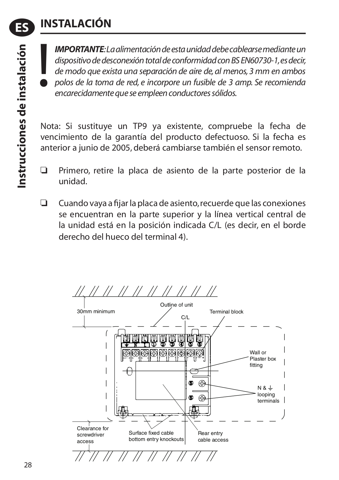
Primero, retire la placa de asiento de la parte posterior de la unidad.

Cuando vaya a fijar la placa de asiento,recuerde que las conexiones se encuentran en la parte superior y la línea vertical central de la unidad está en la posición indicada C/L (es decir, en el borde derecho del hueco del terminal 4).


Outline of unit

30mm minimum

Terminal block


C/L


Wall or Plaster box fitting

N & looping terminals

Clearance for

Surface fixed cable

Rear entry

screwdriver

bottom entry knockouts

cable access

access


28

Fije la placa de asiento a la pared o a la caja encastrada. Los cables de superficie sólo pueden entrar por debajo de la unidad. Si se monta sobre una caja encastrada, los cables pueden entrar por la parte posterior a través de la abertura de la placa de asiento.

Aunque la unidad no necesita conexión a tierra, dispone de dos terminales en la placa de asiento para continuidad de tierra.

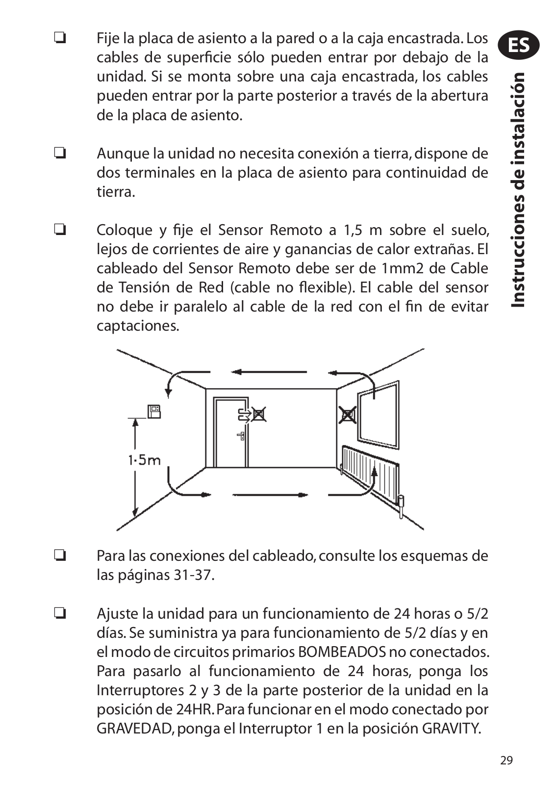
Coloque y fije el Sensor Remoto a 1,5 m sobre el suelo, lejos de corrientes de aire y ganancias de calor extrañas. El cableado del Sensor Remoto debe ser de 1mm2 de Cable de Tensión de Red (cable no flexible). El cable del sensor no debe ir paralelo al cable de la red con el fin de evitar captaciones.

Para las conexiones del cableado, consulte los esquemas de las páginas 31-37.

Ajuste la unidad para un funcionamiento de 24 horas o 5/2 días. Se suministra ya para funcionamiento de 5/2 días y en el modo de circuitos primarios BOMBEADOS no conectados. Para pasarlo al funcionamiento de 24 horas, ponga los Interruptores 2 y 3 de la parte posterior de la unidad en la posición de 24HR. Para funcionar en el modo conectado por GRAVEDAD, ponga el Interruptor 1 en la posición GRAVITY.

ES

<![if ! IE]>

<![endif]>Instrucciones de instalación

29

Loading...
+ 67 hidden pages