

Page 1
MAKING MODERN LIVING POSSIBLE
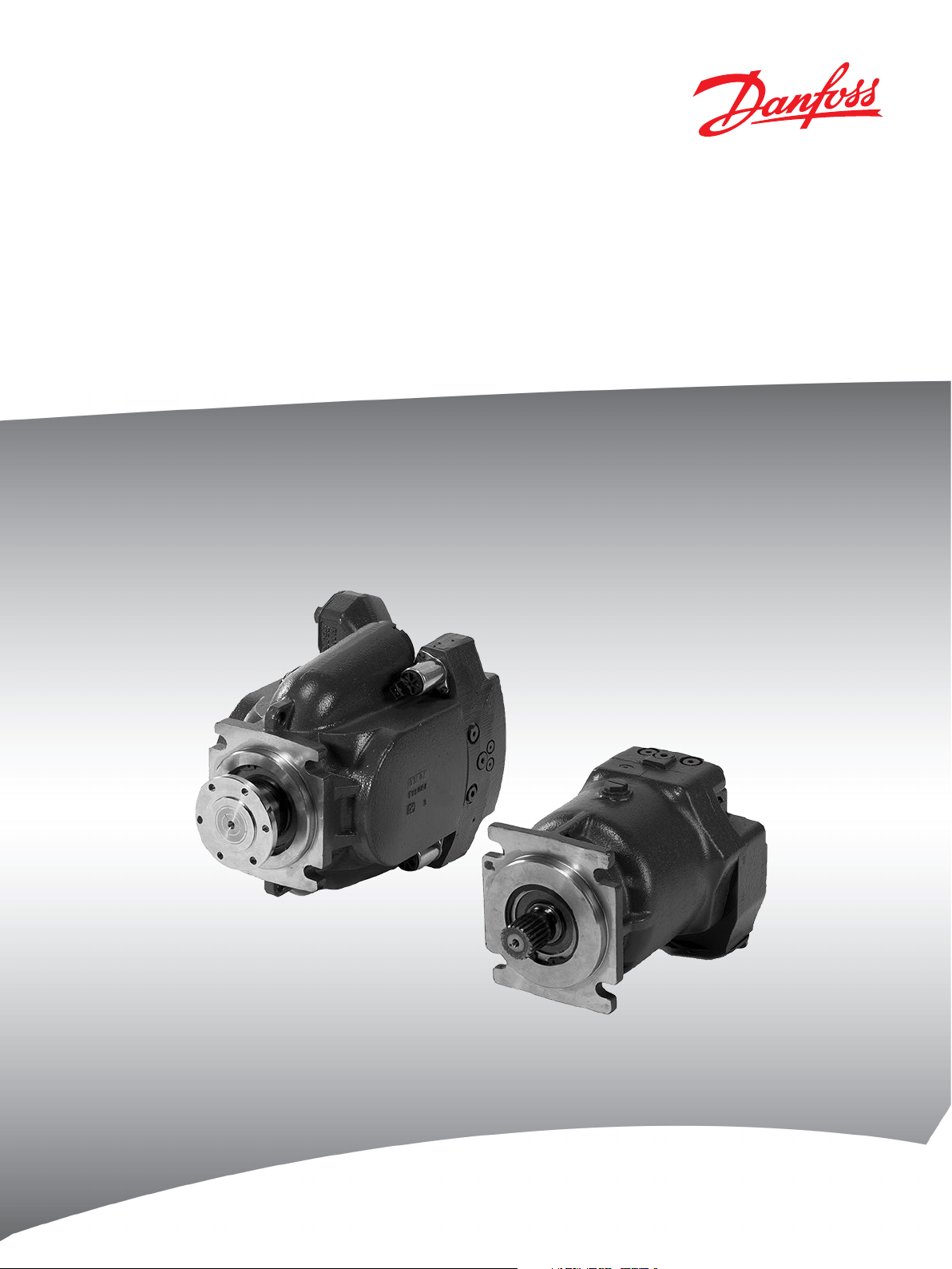
System Description
Transit Mixer Drives System
Series TM
powersolutions.danfoss.com
Page 2

System Description Series TM Transit Mixer Drive System
Revision History Table of Revisions
Date Changed Rev
Mar 2014 Converted to Danfoss layout - DITA CMS CA
December 2010 BB
2 520L0426 • Rev CA • Mar 2014
Page 3

System Description Series TM Transit Mixer Drive System
Contents
Transit Mixer Drive System TM
General.................................................................................................................................................................................................4
Product Features...............................................................................................................................................................................4
System Features................................................................................................................................................................................4
Transit Mixer Pump/TMP and Motor/TMM
General.................................................................................................................................................................................................5
Features................................................................................................................................................................................................5
Functional Description................................................................................................................................................................... 6
Hydraulic Circuit Diagram............................................................................................................................................................. 6
Transit Mixer Electronic Unit TME
General.................................................................................................................................................................................................7
Functional description....................................................................................................................................................................7
Installation space..............................................................................................................................................................................8
Wiring diagram..................................................................................................................................................................................9
Transit Mixer Gearbox TMG
General...............................................................................................................................................................................................10
Transit Mixer System
General...............................................................................................................................................................................................11
Optional....................................................................................................................................................................................... 11
Available outline drawings.........................................................................................................................................................11
520L0426 • Rev CA • Mar 2014 3
Page 4

System Description
Series TM Transit Mixer Drive System
Transit Mixer Drive System TM
General
The new Transit Mixer Drive System -TM for short - from Danfoss is based on more than 30
years‘ experience in the worldwide use of drum drive systems in transit mixers. Innovative electronics
suitable for mobile use, combined with reliable technology, are the result of this development.
Danfoss offers, as a single supplier, complete systems for drum sizes from 6-12 m³ [8-16 yd3] from one
source.
The smart system resets the standard relating to the market requirements for reliability and simple
handling.
Product Features
•
•
Hydrostatic transmission
overall size 070 and 089 cm³ [4.3 and 5.4 in³]
‒
electrical proportional control of the pump
‒
rotational group proven over millions in units
‒
noise reduction by 12 dB (A)
‒
exemplary reductions in overall volume and weight
‒
Operating units
System Features
external and cab-mounted station
‒
simple installation and wiring
‒
electric plug connections suitable for mobile use
‒
no adjustments,“Plug and Perform“
‒
Mixer gearbox
•
overall size 51.2, 61.2 and 71.2
‒
with/without water-pump drive
‒
speed sensor receiving bore as standard
‒
Speed sensor retrofittable without adjustment
‒
no adjustments “Plug and Perform®“
‒
direction of rotation and speed via latched rotary switch on the cab-mounted or external station
•
identical operating elements on the cab-mounted and external stations
•
external station pushbutton: STOP/START the drum
•
external station pushbutton: STOP/START the drum with the cab-mounted station active
•
cab-mounted station pushbutton: change over to external station and vice versa
•
status reporting from the cab-mounted and external stations via LEDs
•
active cab-mounted station during transit means the external station is switched off
•
constant drum speed with variable pump-drive speed
•
constant drum speed, irrespective of the loading of the drum
•
exact repeatability of the drum speed by means of a latched rotary switch
•
automatic maximum drum-speed limitation
•
A convincing, reliable and smart system solution from Danfoss which (at present) is still missing from
your transit mixer?
Contact us! Our worldwide sales organization is ready to serve you.
4 520L0426 • Rev CA • Mar 2014
Page 5

System Description Series TM Transit Mixer Drive System
Transit Mixer Pump/TMP and Motor/TMM
General
The hydrostatic transmission developed by Danfoss for transit mixers, comprising the axial piston
variable displacement pump TMP and the axial piston fixed displacement motor TMM, is based on more
than 30 years‘ experience in the world wide use of pumps/motors in transit mixers.
The demonstrable reliability of the rotational group was decisive in continuing to use these in the new
and innovative drive concept.
In the TMP and TMM the connection sizes (fixing flange/shaft) from series 20 were adopted. The TMP
shaft is designed at the factory with the usual DIN connection flange Ø 100 mm as standard.
The requirements of the market with regard to reducing the overall volume, weight and noise, and also
the electrical pump displacement control - in connection with the introduction of trucks with EURO 2 (3)
diesel engines - have been taken into account accordingly.
Features
All hydraulic connections have metric threads.
Transit Mixer Pump 070 or 89 cm³ [4.3 or 5.4 in³] Transit Mixer Motor 070 or 089 cm³ [4.3 or 5.4 in³]
•
Electrical displacement control
(12 or 24 VDC)
•
operating, suction and leakage oil connections
on one side
•
measurement connections on the rear
•
integrated charge pump (20 cm³)
[1.2 in3]
•
integrated high-pressure relief valves (420 bar)
[6 000 psi]
•
Ø 100 mm-drive flange (DIN/ISO) as standard
Option:
•
through-drive SAE “A“
•
splined shaft
520L0426 • Rev CA • Mar 2014 5
•
operating connections on one side
•
integrated loop flushing device
•
high-pressure measurement
•
connections on one side
Option:
•
speed sensor
Page 6

P001 941
n
System Description
Series TM Transit Mixer Drive System
Transit Mixer Pump/TMP and Motor/TMM
Functional Description
In accordance with the rotary switch position on the TME operating unit, a current set point is generated
and connected to the electrical proportional valve of the TMP as a PWM signal. The necessary control oil
supply is provided by the feed circuit of the charge pump and is delivered to the actuating cylinder via
the electrical proportional valve. Depending on the current value, a proportional actuating pressure is
established on the actuating cylinder, and therefore a stroke, which adjusts the swash plate and defines
the geometric delivery volume of the pump.
Depending on the drive speed of the pump, a pump delivery flow is established which determines the
output speed of the motor or the input speed to the TMG mixer gearbox.
Since the pre-selected drum speed is intended to be kept constant, irrespective of the variable diesel/or
pump drive speed or charging state a speed control system has been implemented.
In order to meet the demand for a constant drum speed the actual value is detected via the speed sensor
in the TMG gearbox and provided as an input signal to the TME operating unit. The electronics compare
the actual value with the pre-selected set point of the drum speed and can re-adjust the current value for
the electrical proportional valves and therefore the geometric delivery volume of the TMP until the two
agree, that is to say the pump delivery flow is kept constant.
The system presented completely meets the demand for a constant drum speed in accordance with
the pre-selection on the rotary switch of the TME operating unit.
The integrated charge pump supplies the closed circuit via 2 multi-function valves - feed and highpressure protection - on the respective low-pressure side, using cooled and filtered oil. The integrated
flushing device in the motor, comprising an alternating slide and permanently set nozzle flushing valve,
ensures a defined exchange of oil in the closed circuit. The oil led via the cooler is fed in again via the
charge pump by means of a suction filtering system connected upstream.
At the time of first commissioning rapid air separation from the high-pressure circuit is also achieved by
the flushing device and, in addition, it is ensured that unavoidable “installation dirt“ is flushed out at the
same time and can be picked up by the suction filtering system.
Hydraulic Circuit Diagram
6 520L0426 • Rev CA • Mar 2014
Page 7

System Description
Series TM Transit Mixer Drive System
Transit Mixer Electronic Unit TME
General
The Transit Mixer Electronic Unit -TME for short - constitutes a ready-to-install operating unit for the
Danfoss drum drive system for transit mixers and is available as an external and cab-mounted operating
unit.
Both operating units are designed as build-in modules and completely encapsulated. The electrical lines
are produced in an operationally reliable way via mechanically locked AMP plug-connector systems
suitable for mobile use.
The operating units are in each case fixed into the specific housing of the transit mixer manufacturer via
(2) fastening angles in each case forming part of the scope of supply. The flat seal also supplied effectively
prevents dirt and water penetration if the installation instructions are complied with.
The cab-mounted operating unit is an additional device and can be operated only in conjunction with
the external operating unit.
The qualification tests with regard to EMC and ESD resistance, vibration, shock and temperature and also
salt-spray testing were passed successfully.
The simple wiring and installation - no adjustments - are features of this smart solution.
”Plug and Perform®“, the Danfoss concept
Functional description
Using the rotary switch on the operating unit, the direction and speed of rotation of the drum are preselected and, corresponding to the position of the rotary switch, a current value is supplied to the
electrical pump control. The pump delivery current which is established determines the reference motor
speed at the input of the mechanical gearbox. The speed sensor in the mixer gearbox registers the actual
speed as a feedback variable for the electronics. The desired and actual values are compared and
readjusted until both values agree, that is to say for the transit mixer, drum speed control in any selected
position.
Using the central rotary switch, the direction of rotation and speed are pre-selected.
Charging/Transport : 3 positions (2-10-14 rev/min)/ to the right of the LED
•
Neutral/Stop : 1 position (0 rev/min) corresponding to the position of the LED
•
Discharging : 7 positions (1-2-4-6-8-10-14 rev/min)/ to the left of the LED
•
The yellow pushbutton on the external operating station permits the drum to be stopped/started from a
pre-selected direction of rotation and speed. The LED signals the status of the operating unit.
press briefly : the drum stops /LED flashes
•
press again : the drum starts /LED lights up
•
The yellow pushbutton on the cab-mounted operating station permits a changeover to the external
operating station and vice versa. The LED indicates the status of the operating unit.
press briefly : cab unit switched on/LED lights up - external switched off /LED off
•
press again : cab switched off /LED off - external in ”stand by“/LED flashes
•
520L0426 • Rev CA • Mar 2014 7
Page 8

72.4 ± 0.3
[2.85 ±0.01]
93.4 ±0.3
[3.68 ±0.01]
R3 ±0.1
[0.12 ±0.004]
max. 5
[0.20]
min. 1
[0.04]
min. 50
[1.97]
mm
[in]
P001 937E
P001 938
System Description
Series TM Transit Mixer Drive System
Transit Mixer Electronic Unit TME
When the cab-mounted operating station is active, the yellow pushbutton on the external operating
station can likewise be used to stop/start the drum, e.g. EMERGENCY STOP or for pouring foundations for
kerbstones.
press briefly : stop the drum/cabin LED flashes
•
press again : start the drum/cab LED lights up
•
A transfer of functions from the cab to the external operating station is signalled by the flashing LED on
the external operating station in the ”stand by“ operating mode
set the rotary switch to neutral
•
press the yellow pushbutton briefly, this means : LED lights up and station is switched on
•
Installation space
In order to accommodate the TME in the customer-specific housing, it is merely necessary to produce a
cut-out having the dimensions illustrated above. The housing wall thickness must not be less than 1.0
mm [0.04 in] or more than 5.0 mm [0.20 in].
The minimum installation depth is 50.0 mm [1.97 in]. Fixing/clamping in the customer-specific housing is
carried out via the (2) fixing angles, using (2) screws in each case and forms part of the scope of supply of
the TME.
8 520L0426 • Rev CA • Mar 2014
Page 9

External
stop switch
P001 939E
-
+
F
4A
Batt.
12/24V
DC
Battery (+)
Battery (-)
VCC Voltage (+)
1
2
3
Remote Station Cabin Station
4
5
6
7
8
9
10
11
12
13
14
15
16
Setpoint from Cabin
12V Valve (-)
24V Valve (-)
Remote/ON
Memoblink
PPU (-)
GND
Disable lost of feedback
PPU signal
Ext. Stop
VCC/2
VCC Voltage (+)
Setpoint to Remote
Remote/ON
Memoblink
GND
VCC/2
Valve 1 (+)
Valve 0 (+)
1
2
3
4
5
6
7
8
9
10
11
12
13
14
15
16
(+)
Proportional valve 0
CHARGE
Proportional valve 1
DISCHARGE
PPU (2-wire)
AMP connector, 16-pin AMP connector, 16-pin
Option: Safety function can be
invalidate by connecting.
System Description Series TM Transit Mixer Drive System
Transit Mixer Electronic Unit TME
Wiring diagram
By connecting the pins of the TME appropriately, the operating units can be operated with 12 or 24 VDC;
depending on the respectively available on-board voltage of the truck.
520L0426 • Rev CA • Mar 2014 9
Page 10

System Description Series TM Transit Mixer Drive System
Transit Mixer Gearbox TMG
General
In connection with the hydrostatics developed specifically for the application with electrical pump
control in the closed control loop, all the available TMGs are prepared as standard for subsequent
retrofitting with a speed sensor. At the factory the receiving bore is closed by an oil-tight cover.
The new drive system presented here for Transit Mixer -TM for short - generally needs the speed sensor.
Because of the design of the construction, this can be retrofitted simply. Adjustment of the speed sensor known from other designs - is dispensed with.
In addition product improvements as compared with the mixer gearboxes of the HPM series have been
included in series production.
Since the mixer gearbox constitutes part of the overall TM system, the same designation logic applies as
that used in the other products specific to an application, that is to say Transit Mixer Gearbox - TMG for
short - plus the further type designation known from the HPM series.
Three overall sizes - 51.2/ 61.2/ 71.2 - can be supplied both without and with the connection option for a
water pump - optionally on the right or left.
Size 61.2 with water-pump connection and speed
sensor
Speed sensor
10 520L0426 • Rev CA • Mar 2014
Page 11

System Description Series TM Transit Mixer Drive System
Transit Mixer System
General
Depending on the drum size, the following products can be supplied as a system solution as standard.
6 - 8 m³ [8-10 yd³] TMP070-TMM070-TMG51.2/i=103 TMG optionally without/with water-pump drive
8 - 10 m³ [10-13 yd³] TMP089-TMM089-TMG61.2/i=112 TMG optionally without/with water-pump drive
10 - 12 m³ [13-16 yd³] TMP089-TMM089-TMG71.2/i=131 TMG optionally without/with water-pump drive
Irrespective of the drum size the following products complete the system solution.
TME remote operating station
•
TME cab-mounted operating station
•
speed sensor, complete
•
Optional
•
mating connector for the TME operating station
•
mating connector for the proport. valves of the variable displacement pump TMP
Available outline drawings
Outline Drawings
Series Ident. No.
TMP070/089 513 076
TMM070/089 520 118
TMG 51.2 443 879
TMG 61.2 480 814
TMG 71.2 445 981
520L0426 • Rev CA • Mar 2014 11
Page 12

Danfoss Power Solutions is a global manufacturer and supplier of high-quality hydraulic and
electronic components. We specialize in providing state-of-the-art technology and solutions that
excel in the harsh operating conditions of the mobile off -highway market. Building on our extensive
applications expertise, we work closely with our customers to ensure exceptional performance for a
broad range of off -highway vehicles.
We help OEMs around the world speed up system development, reduce costs and bring vehicles to
market faster.
Danfoss – Your Strongest Partner in Mobile Hydraulics.
Go to www.powersolutions.danfoss.com for further product information.
Wherever off -highway vehicles are at work, so is Danfoss.
We off er expert worldwide support for our customers, ensuring the best possible solutions for
outstanding performance. And with an extensive network of Global Service Partners, we also provide
comprehensive global service for all of our components.
Please contact the Danfoss Power Solution representative nearest you.
Danfoss
Power Solutions GmbH & Co. OHG
Krokamp 35
D-24539 Neumünster, Germany
Phone: +49 4321 871 0
Danfoss
Power Solutions ApS
Nordborgvej 81
DK-6430 Nordborg, Denmark
Phone: +45 7488 2222
Danfoss
Power Solutions US Company
2800 East 13th Street
Ames, IA 50010, USA
Phone: +1 515 239 6000
Danfoss
Power Solutions
(Shanghai) Co. Ltd.
Building #22, No. 1000 Jin Hai Rd
Jin Qiao, Pudong New District
Shanghai, China 201206
Phone: +86 21 3418 5200
Products we off er:
• Bent Axis Motors
• Closed Circuit Axial Piston
Pumps and Motors
• Displays
• Electrohydraulic Power
Steering
• Electrohydraulics
• Hydraulic Power Steering
• Integrated Systems
• Joysticks and Control
Handles
• Microcontrollers and
Software
• Open Circuit Axial Piston
Pumps
• Orbital Motors
• PLUS+1® GUIDE
• Proportional Valves
• Sensors
• Steering
• Transit Mixer Drives
Comatrol
www.comatrol.com
Schwarzmüller-Inverter
www.schwarzmuellerinverter.com
Turolla
www.turollaocg.com
Valmova
www.valmova.com
Hydro-Gear
www.hydro-gear.com
Daikin-Sauer-Danfoss
www.daikin-sauer-danfoss.com
Local address:
Danfoss can accept no responsibility for possible errors in catalogues, brochures and other printed material. Danfoss reserves the right to alter its products without notice. This also applies to
products already on order provided that such alterations can be made without subsequential changes being necessary in specifications already agreed.
All trademarks in this material are property of the respective companies. Danfoss and the Danfoss logotype are trademarks of Danfoss A/S. All rights reserved.
520L0426 • Rev CA • Mar 2014 www.danfoss.com
©
Danfoss A/S, 2014
 Loading...