

Page 1
MAKING MODERN LIVING POSSIBLE
Data Sheet
Transit Mixer Pump 070/089 cm
TMP EDC
3
For more than 40 years, Danfoss has been
developing state-of-the-art components and
systems for mobile machinery used in
off-highway operations around the world.
We have become a preferred supplier by
offering the best of what really matters: The
hardware inside your vehicle application.
TMP EDC – our new generation of servocontrolled hydrostatic pumps – has been
specially designed for Transit Mixer
applications.
The TMP EDC is built around an advanced
electrical control and is available in 70 cm³
and 89 cm³ pump displacements. Offering high
quality and reliability, the new pump provides
expanded functionality, greater total efficiency,
and easy installation on the Transit Mixer.
The TMP EDC control and sensors options are
PLUS+1® Compliant. PLUS+1 allows you to
rapidly develop and customize electronic
machine control. It opens up the future by
combining machine controls and diagnostics
in an integrated operating network.
Features y Designed for quality and reliability
– Designed specifically for Transit Mixer
applications
– Robust rotating group concept
– Based on the latest technological
developments
y Installation and packaging benefits
– All connections are located on one side
– Include Manual Overides
– Length optimized pump
– Through drive pump
– Coupling flange or spline shaft availability
– High corner power
– Standard connector interface
– Metric connections
– Expanded functionality through PLUS+1®
L1109001 • Rev BA • Jan 2014
y Optimized for electrical control
– Electrohydraulic control including Electrical
Displacement Control (EDC)
y Expanded functionality
– PLUS+1 Compliant control and sensor
options
– Speed and temperature sensors
y Greater total efficiency
– Minimized control losses
– Proven rotating group from Series 20
– Low control pressure and control loses
Page 2
Data Sheet Transit Mixer Pump 070/089 cm3, TMP EDC
[11.496 ]
[12.458]
0
Split ange boss
Charge pump inlet S
43.9
M12x1.5; 12.7 [.5] full thread depth
M12x1.5; 12.7 [.5] full thread depth
M06-6S
Ø71.7 max [Dia2.823]
Ø71.7 max [Dia2.823]
to be paint free
Physical properties
Features Unit
3
Displacement cm
Weight dry
(standard)
[in3] 68 .3 [4 .17] 89.0 [5.43]
kg [lb] 61 [135]
070 089
Operating parameters
Features Unit
Input
speed
System
pressure
Case
pressure
* Applied pressures above maximum working pressure requires Danfoss application approval.
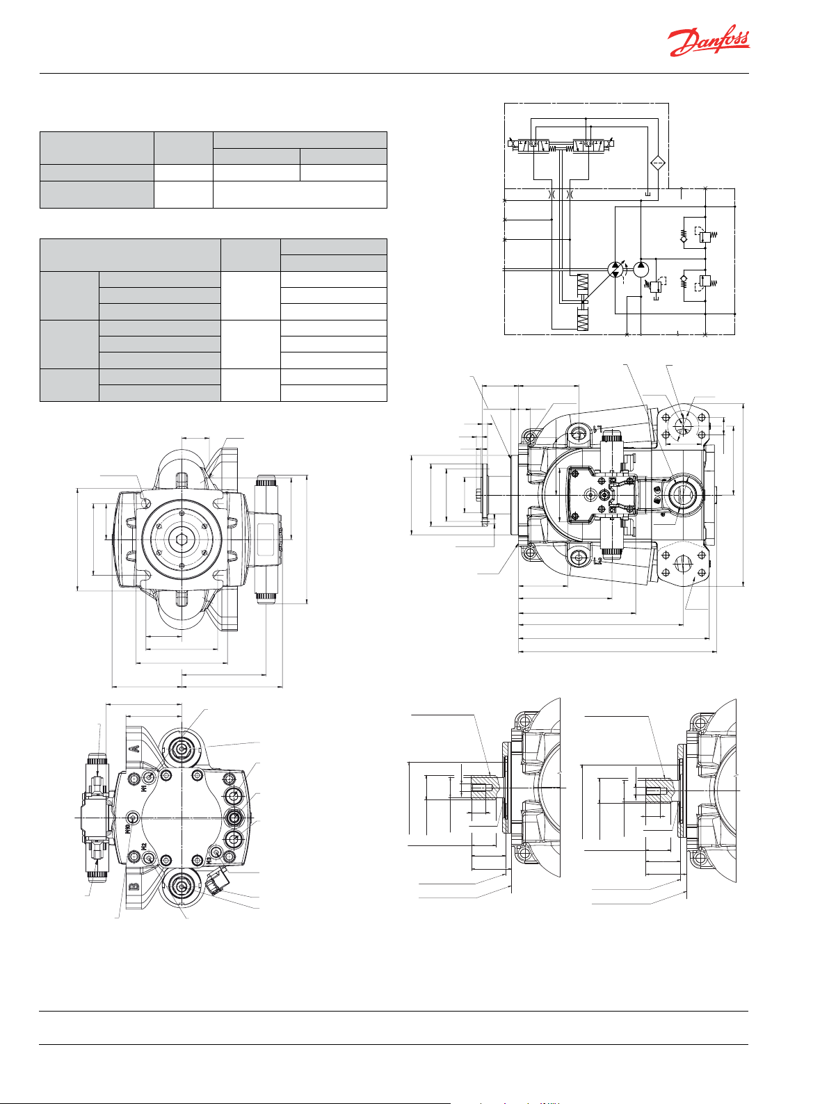
Dimensions
Deutsch DT04-2P
P0055 69
Connector CB
Deutsch DT04-2P
Charge pump inlet pressure
Danfoss
Power Solutions (US) Company
2800 East 13th Street
Ames, IA 50010, USA
Phone: +1 515 239 6000
Danfoss can accept no responsibility for possible errors in catalogues, brochures and other printed material. Danfoss reserves the right to alter its products without notice. This also applies to products
already on order provided that such alterations can be made without subsequential changes being necessary in specifications already agreed.
All trademarks in this material are property of the respective companies. Danfoss and the Danfoss logotype are trademarks of Danfoss A/S. All rights reserved.
L1109001 • Rev BA • Jan 2014 www.danfoss.com © Danfoss A/S, 2014-01
Minimum
Rated 2500
Maximum 2900
Max. working pressure*
Maximum pressure 450 [6525]
Minimum pressure 10 [145]
Rated pressure
Maximum pressure 5.0 [73]
[1.728]
+0.8
Ø15
-0.3
+0.031
[Dia 0.591 ]
-0.012
57.25
[2.254]
164
114.5
[6.457]
[4.508]
57.25
[2.254]
114.5
[4.508]
146
[5.748]
111.4
[4.386]
121
[4.764]
89
Connector CB
Gauge port M10
[3.504]
Gauge port M2
System pressure Port B,
min
(rpm)
bar
[psi]
bar
[psi]
Case drain port L1
use highest port as outlet
M22x1.5 - 11 min [.433] depth
134.8
[5.306]
160.8
[6.329]
Gauge port M1
System pressure Port A, M12x1.5
12.7 [0.5] full thread depth
Danfoss
Power Solutions GmbH & Co. OHG
Krokamp 35
D-24539 Neumünster, Germany
Phone: +49 4321 871 0
Size
-1
98.8
[3.89]
Gauge port M4
Servo pressure M12x1.5
High pressure relief valve
Port A
Charge pressure relief valve
High pressure relief valve
Port B
Gauge port M3
Charge pressure M12x1.5
12.7 [0.5] full thread depth
Connector Deutsch DT
Gauge port M5
Servo pressure M12x1.5
Size
070 / 089
500
420 [6090]
3.0 [44]
206
[8.11]
M3
M5
M4
P00 5447
Auxiliary mounting pad
Flange 127 - 4
per ISO3019 (SAE J744C)
0
-0.05
-0.002
Ø127
Ø100 ±0.3
[Dia 3.937 ±0.012]
[Dia 4.999 ]
Ø84
[Dia 3.307 ]
[Dia 0.319 ]
[0.366]
[0.091]
0
[0.335]
9.3
2.3
-0.06
57
[0.488 ±0.01]
8.5
0
-0.002
[2.244 ]
+0.23
Ø8.1
+0.08
+0.009
+0.003
Paint free
58.2
[2.291]
12.4 ±0.25
[0.738]
18.8
78.4
[3.086]
[3.781]
96
Ø12.5
[Dia0.492]
92
[3.624]
86
149
[5.87]
P00557 0
ISO 3019-1 (SAE C, 23-teeth) ISO 3019-1 (SAE C, 21-teeth)
Spline data:
Number of teeth: 23
Pitch fraction: 16/32
Pressure angle: 30°
Pitch Ø: 36.513 [1.438]
Meas. over pins: 40.973/41.024
[1.6131/1.6151]
Pin Ø: 3.048 [0.12]
M10-6H
Coupling Diameter
Ø37.6 ±0.09
Full spline lenght
Coupling must not protrude
beyond this point
Mounting ange surface
Flange SAE-C per ISO 3019-1
to be paint free
Danfoss
Power Solutions ApS
Nordborgvej 81
DK-6430 Nordborg, Denmark
Phone: +45 7488 2222
0
-0.2
Ø32
[Dia1.48 ±0.004]
34.35
[1.352 ]
0
-0.08
[0.079 ±0.004]
[Dia1.26 ]
0
-0.5
0
-0.02
20 min
[0.787]
R2 ±0.11
47.5 ±0.2
[1.87 ±0.008]
[2.205]
56
CBCA
M42x2 - 6H
20 [0.79] full thread depth
Ø26 (2x)
[Dia1.024]
60
304.5
[11.99]
316.4
0
[1.352 ]
0
-0.2
-0.08
Ø29
[Dia1.142 ]
34.35
-0.5
0
-0.02
M10-6H
[0.079 ±0.004]
0
[2.362]
[Dia 2.362]
20 min
[0.787]
R2 ±0.11
47.5 ±0.2
[1.87 ±0.008]
Ø60
[2.205]
56
[3.386]
187
[7.366]
263
[10.353]
Spline data:
Number of teeth: 21
Pitch fraction: 16/32
Pressure angle: 30°
Pitch Ø: 33.338 [1.313]
Meas. over pins: 37.783/37.833
[1.4875/1.4895]
Pin Ø: 3.048 [0.12]
Coupling Diameter
Ø34.41 ±0.09
Full spline lenght
Coupling must not protrude
beyond this point
Mounting ange surface
Flange SAE-C per ISO 3019-1
[Dia1.355 ±0.004]
Danfoss
Power Solutions
(Shanghai) Co. Ltd.
Building #22, No. 1000 Jin Hai Rd
Jin Qiao, Pudong New District
Shanghai, China 201206
Phone: +86 21 3418 5200
SchematicTechnical Specifications
M1
L1
L2S M2M10
DN25 typ I 420 bar
Series per ISO 6162
M12, 21 [0.83] full thread depth
Ø50 min
[Dia1.97]
57.2 (2x)
[2.252]
Paint free
[1.094 ]
27.8 (2x)
P005 429EP005 428E
A
B
110
[4.331]
292
 Loading...