

Page 1
Service Manual
Transit Mixer Axial Piston Pump
Size 070/089
powersolutions.danfoss.com
Page 2
Service Manual
TMP Transit Mixer Axial Piston Pump, Size 070/089
Revision history Table of revisions
Date Changed Rev
July 2017 Updated to Engineering Tomorrow 0203
Mar 2014 Converted to Danfoss layout – DITA CMS BB
19 Oct, 2012 Major update - The MDC control added BA
14 Oct, 2011 Images data change AE
Jul, 2011 Grammar spelling, new images with speed sensor AD
02 Nov, 2010 No technical change, word spelling AC
24 Aug, 2010 New Backpage AB
24 Jun, 2010 First Edition AA
2 | © Danfoss | July 2017 L1010109 | AX00000131en-US0203
Page 3

Service Manual
TMP Transit Mixer Axial Piston Pump, Size 070/089
Contents
Literature reference
TMP literature reference ............................................................................................................................................................... 5
Introduction
Overview..............................................................................................................................................................................................6
Warranty.............................................................................................................................................................................................. 6
Symbols used in Danfoss literature............................................................................................................................................6
General instructions........................................................................................................................................................................ 6
Safety precautions............................................................................................................................................................................7
Unintended machine movement..........................................................................................................................................8
Flammable cleaning solvents.................................................................................................................................................8
Fluid under pressure..................................................................................................................................................................8
Personal safety............................................................................................................................................................................. 8
Hazardous material.................................................................................................................................................................... 8
Design...................................................................................................................................................................................................8
System circuit.....................................................................................................................................................................................9
Basic Closed Circuit.....................................................................................................................................................................9
Case drain and heat exchanger..............................................................................................................................................9
Operation
High pressure relief valve (HPRV) and charge check valve.............................................................................................11
Charge pressure relief valve (CPRV) ....................................................................................................................................... 12
Electrical Displacement Control (EDC)................................................................................................................................... 12
EDC Principle..............................................................................................................................................................................12
Manual Displacement Control (MDC).....................................................................................................................................13
MDC principle............................................................................................................................................................................ 13
MDC with control cut off (CCO)...........................................................................................................................................13
Manual Over Ride (MOR)............................................................................................................................................................. 14
Operating Parameters
Overview........................................................................................................................................................................................... 15
Input Speed......................................................................................................................................................................................15
System Pressure..............................................................................................................................................................................15
Charge Pressure..............................................................................................................................................................................15
Charge inlet pressure....................................................................................................................................................................16
Case Pressure...................................................................................................................................................................................16
Temperature and Viscosity.........................................................................................................................................................16
Temperature...............................................................................................................................................................................16
Viscosity........................................................................................................................................................................................16
General specification.................................................................................................................................................................... 16
Physical Properties.........................................................................................................................................................................17
Operating parameters..................................................................................................................................................................17
Fluid Specifications....................................................................................................................................................................... 18
Fluid and Filter Maintenance
Fluid and filter recommendations........................................................................................................................................... 19
Port Locations and Gauge Installation...................................................................................................................................19
Initial Startup Procedures
General ..............................................................................................................................................................................................21
Start-Up procedure........................................................................................................................................................................21
Troubleshooting
Overview........................................................................................................................................................................................... 22
Safety Precautions......................................................................................................................................................................... 22
Electrical Troubleshooting (TMP EDC)....................................................................................................................................22
System Operating Hot..................................................................................................................................................................22
Neutral Difficult or Impossible to Find................................................................................................................................... 23
System Will Not Operate in Either Direction........................................................................................................................23
System Noise or Vibration...........................................................................................................................................................24
Sluggish System Response.........................................................................................................................................................24
Transmission Operates Normally in One Direction Only.................................................................................................24
©
Danfoss | July 2017 L1010109 | AX00000131en-US0203 | 3
Page 4

Service Manual
TMP Transit Mixer Axial Piston Pump, Size 070/089
Contents
Adjustments
Pump Adjustment..........................................................................................................................................................................25
Standard Procedures.................................................................................................................................................................... 25
Charge Pressure Relief Valve Adjustments...........................................................................................................................25
EDC neutral adjustment.............................................................................................................................................................. 26
MDC Control Neutral Adjustment............................................................................................................................................27
Mechanical Neutral Adjustment...............................................................................................................................................29
Pump setup.................................................................................................................................................................................31
Servo adjustment..................................................................................................................................................................... 31
Minor Repair
Standard Procedures, Removing the Pump.........................................................................................................................32
Disassembly................................................................................................................................................................................32
Inspection....................................................................................................................................................................................32
Reassembly................................................................................................................................................................................. 32
EDC/MDC Control.......................................................................................................................................................................... 32
Removal........................................................................................................................................................................................32
Inspection....................................................................................................................................................................................32
Reassembly................................................................................................................................................................................. 32
EDC Control......................................................................................................................................................................................34
Control Solenoids...........................................................................................................................................................................35
Removal........................................................................................................................................................................................35
Inspection....................................................................................................................................................................................35
Reassembly................................................................................................................................................................................. 35
MDC with CCO Control................................................................................................................................................................ 36
Control Solenoids...........................................................................................................................................................................37
Removal........................................................................................................................................................................................37
Inspection....................................................................................................................................................................................37
Reassembly................................................................................................................................................................................. 37
Shaft Seal Replacement...............................................................................................................................................................37
Removal........................................................................................................................................................................................38
Inspection....................................................................................................................................................................................38
Reassembly................................................................................................................................................................................. 38
Charge Pump...................................................................................................................................................................................38
Charge Pump Removal (Removable Auxiliary Pad/Cover)........................................................................................38
Inspection....................................................................................................................................................................................39
Reassembly................................................................................................................................................................................. 39
High Pressure Relief Valves (HPRV)..........................................................................................................................................40
Removal........................................................................................................................................................................................40
Inspection....................................................................................................................................................................................40
Reassembly................................................................................................................................................................................. 40
Charge Pressure Relief Valve......................................................................................................................................................41
Removal........................................................................................................................................................................................41
Inspection....................................................................................................................................................................................41
Reassembly................................................................................................................................................................................. 41
Torque Chart
Fastener Size and Torques..........................................................................................................................................................43
Plug Size and Torques..................................................................................................................................................................43
EDC Fasteners and Plugs.............................................................................................................................................................43
MDC Fasteners and Plugs........................................................................................................................................................... 45
4 | © Danfoss | July 2017 L1010109 | AX00000131en-US0203
Page 5

Service Manual
TMP Transit Mixer Axial Piston Pump, Size 070/089
Literature reference
TMP literature reference
Further available literature
Description
TMP Transit Mixer Axial Piston Pump, Size 070/089
TMP Transit Mixer Axial Piston Pump, Size 070/089
TMP Transit Mixer Axial Piston Pump, EDC/MDC, Size 070/089
TMP Transit Mixer Axial Piston Pump, NFPE, Size 070/089
TMP EDC Axial Piston Pump, Size 070/089
TMP MDC Axial Piston Pump, Size 070/089
H1 Electrical Displacement Control (EDC)
Speed and Temperature Sensor
Hydraulic Fluids and Lubricants
Design Guideline for Hydraulic Fluid Cleanliness
Type
Technical Information
Service Manual
Repair Instruction
Repair Instruction
Datasheet
Datasheet
Technical Information
Technical Information
Technical Information
Technical Information
Literature number
L1006391
L1010109
L1031073
11029271
L1109001
L1214176
11022744
11046759
520L0463
520L0467
©
Danfoss | July 2017 L1010109 | AX00000131en-US0203 | 5
Page 6
Service Manual
TMP Transit Mixer Axial Piston Pump, Size 070/089
Introduction
Overview
This manual includes information on the installation, maintenance, and minor repair of TMP pumps. It
includes a description of the unit and its individual components, troubleshooting information, and minor
repair procedures.
Performing minor repairs requires the unit to be removed from the vehicle/machine. Thoroughly clean
the unit before beginning maintenance or repair activities. Since dirt and contamination are the greatest
enemies of any type of hydraulic equipment, follow cleanliness requirements strictly. This is especially
important when changing the system filter and when removing hoses or plumbing.
A worldwide network of Danfoss Authorized Service Centers is available for major repairs. Danfoss trains
and certifies Authorized Service Centers on a regular basis. You can locate your nearest Authorized
Service Center using the distributor locator at www.sauer-danfoss.com.
Warranty
Performing adjustments and minor repairs according to the procedures in this manual will not affect your
warranty. Major repairs requiring the removal of a unit's center section, servo sleeves, or front flange
voids the warranty unless a Danfoss Authorized Service Center performs them.
Symbols used in Danfoss literature
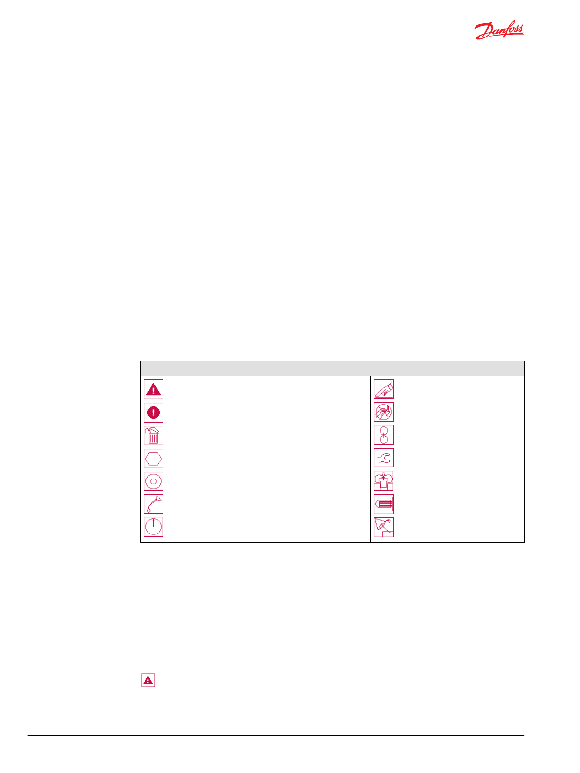
Service symbols used in Danfoss literature
Symbol description
The symbols above appear in the illustrations and text of this manual. They are intended to communicate
helpful information at the point where it is the most useful to the reader. In most instances, the
appearance of the symbol itself denotes its meaning. The legend above defines each symbol and
explains its purpose.
WARNING may result in injury
CAUTION may result in damage to product or property
Non-reusable part, use a new part
External hex head
Internal hex head
Lubricate with hydraulic fluid
Pressure measurement/gauge location or specification
Clean area or part
Be careful not to scratch or damage
Note correct orientation
Torque specification
Pull out with tool – press fit
Cover splines with installation sleeve
Inspect for wear or damage
General instructions
Follow the general procedures below when repairing TMM constant displacement closed circuit motors:
Remove the unit
Prior to performing major repairs, remove the unit from the vehicle/machine. Chock the wheels on
the vehicle or lock the mechanism to inhibit movement. Be aware that hydraulic fluid may be under high
pressure and/or hot. Inspect the outside of the pump and fittings for damage. Cap hoses and plug ports
after removal to prevent contamination.
6 | © Danfoss | July 2017 L1010109 | AX00000131en-US0203
Page 7

W
W
W
W
Service Manual
TMP Transit Mixer Axial Piston Pump, Size 070/089
Introduction
Keep it clean
Cleanliness is a primary means of assuring satisfactory motor life on both new and repaired units.
Clean the outside of the motor thoroughly before disassembly. Take care to avoid contamination of the
system ports. Cleaning parts by using a clean solvent wash and air drying is usually adequate. As with any
precision equipment, you must keep all parts free of foreign material and chemicals. Protect all exposed
sealing surfaces and open cavities from damage and foreign material. If left unattended, cover the pump
with a protective layer of plastic.
Replace all O-rings and gaskets
We recommend you replace all O-rings and seals during service. Lightly lubricate O-rings with clean
petroleum jelly prior to assembly.
Secure the unit
For repair, place the unit in a stable position with the shaft pointing downward. It will be necessary to
secure the motor while removing and torquing fasteners and components.
Safety precautions
Always consider safety precautions before beginning a service procedure. Take the following general
precautions whenever servicing a hydraulic system:
Warning
Unintended machine movement
Unintended movement of the machine or mechanism may cause injury to the technician or bystanders.
To protect against unintended movement, secure the machine or disable/disconnect the mechanism
while servicing.
Warning
Flammable cleaning solvents
Some cleaning solvents are flammable. To avoid possible fire, do not use cleaning solvents in an area
where a source of ignition may be present.
Warning
Fluid under pressure
Escaping hydraulic fluid under pressure can have sufficient force to penetrate your skin causing serious
injury and/or infection. This fluid may also be hot enough to cause burns. Use caution when dealing with
hydraulic fluid under pressure. Relieve pressure in the system before removing hoses, fittings, gauges, or
components. Never use your hand or any other body part to check for leaks in a pressurized line. Seek
medical attention immediately if you are cut by hydraulic fluid.
Warning
Personal safety
Protect yourself from injury. Use proper safety equipment including safety glasses at all times.
©
Danfoss | July 2017 L1010109 | AX00000131en-US0203 | 7
Page 8

W
W
W
W
W
W
Service Manual
TMP Transit Mixer Axial Piston Pump, Size 070/089
Introduction
Warning
Hazardous material
Hydraulic fluid contains hazardous material. Avoid contact with hydraulic fluid. Always dispose of used
hydraulic fluid according to state and federal environmental regulations.
Unintended machine movement
Warning
Unintended machine movement
Unintended movement of the machine or mechanism may cause injury to the technician or bystanders.
To protect against unintended movement, secure the machine or disable/disconnect the mechanism
while servicing.
Flammable cleaning solvents
Warning
Flammable cleaning solvents
Some cleaning solvents are flammable. To avoid possible fire, do not use cleaning solvents in an area
where a source of ignition may be present.
Fluid under pressure
Warning
Fluid under pressure
Escaping hydraulic fluid under pressure can have sufficient force to penetrate your skin causing serious
injury and/or infection. This fluid may also be hot enough to cause burns. Use caution when dealing with
hydraulic fluid under pressure. Relieve pressure in the system before removing hoses, fittings, gauges, or
components. Never use your hand or any other body part to check for leaks in a pressurized line. Seek
medical attention immediately if you are cut by hydraulic fluid.
Personal safety
Warning
Personal safety
Protect yourself from injury. Use proper safety equipment including safety glasses at all times.
Hazardous material
Warning
Hazardous material
Hydraulic fluid contains hazardous material. Avoid contact with hydraulic fluid. Always dispose of used
hydraulic fluid according to state and federal environmental regulations.
Design
Danfoss TMP closed circuit piston pumps convert input torque into hydraulic power. The input shaft
transmits rotational force to the cylinder block. Bearings at the front and rear of the pump support the
8 | © Danfoss | July 2017 L1010109 | AX00000131en-US0203
Page 9
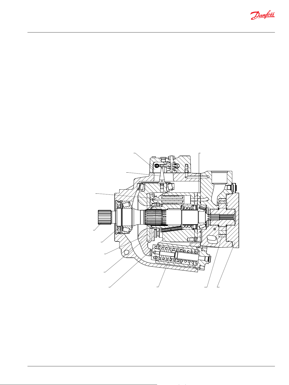
Electric displacement control
Valve plate
Piston
Shaft
Shaft seal
Plate thrust
Swashplate
Swashplate feedback pin
Cylinder block Servo piston Charge pump
Cover charge pump
Service Manual
TMP Transit Mixer Axial Piston Pump, Size 070/089
Introduction
shaft. Splines connect the shaft to the cylinder block. A lip-seal at the front end of the pump prevents
leakage where the shaft exits the pump housing. The spinning cylinder block contains nine reciprocating
pistons. Each piston has a brass slipper connected at one end by a ball joint. The block springs, ball guide,
and slipper retainer hold the slippers to the swashplate. The reciprocating movement of the pistons
occurs as the slippers slide against the inclined swashplate during rotation. Via the valve plate, one half of
the cylinder block is connected to low pressure and the other half to high pressure. As each piston cycles
in and out of its bore, fluid is replenished by charge flow and displaced to the outlet thereby imparting
hydraulic power into the system. A small amount of fluid is allowed to flow from the cylinder block/valve
plate and slipper/swashplate interfaces for lubrication and cooling. Case drain ports return this fluid to
the reservoir.
The angle of the swashplate controls the volume and direction of fluid displaced into the system. The
servo piston controls the angle of the swashplate. The pump control, by varying the pressure at the servo
piston, controls the piston's position. An electric signal to the control coils or mechanical signal to the
control transmits the command from the operator to the pump. Mechanical feedback of the swashplate
position to the control through the feedback pins allows for very precise displacement control and
increases overall system stability.
Cross section view of TMP
System circuit
Basic Closed Circuit
Hydraulic lines connect the main ports of the pump to the main ports of the motor. Fluid flows in either
direction from the pump to the motor and back. Either of the hydraulic lines can be under high pressure.
In pumping mode the position of the pump swashplate determines which line is high pressure as well as
the direction of fluid flow.
Case drain and heat exchanger
The pump and motor require case drain lines to remove hot fluid from the system. The pump and motor
drain from the topmost port to ensure the cases remain full of fluid. The motor case drain can connect to
©
Danfoss | July 2017 L1010109 | AX00000131en-US0203 | 9
Page 10
AA
B B
L2 M3
M3
M5
M4
TMMTMP
M2L2SM2
M10
L1
C2C1
M1 L1 M1
AA
B B
L2 M3
M3
M5
M4
TMMTMP
M2
L2
M2
M10
L1 M1 L1 M1
N
‘-’ ‘+’
CW
S
Service Manual
TMP Transit Mixer Axial Piston Pump, Size 070/089
Introduction
the lower drain port on the pump housing or it can tee into the case drain line upstream of the heat
exchanger. A heat exchanger with bypass valve cools the case drain fluid before it returns to the
reservoir.
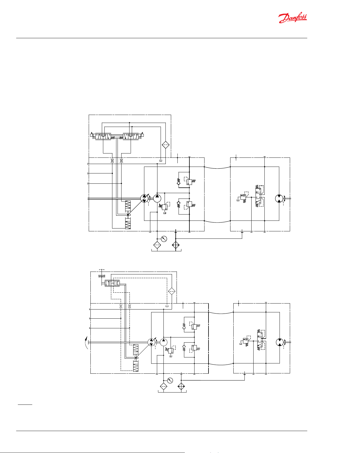
The schematics below show the function of a hydrostatic transmission using an TMP axial variable
displacement pump with electric/manual proportional displacement control (EDC/MDC) and an TMM
fixed displacement motor with integrated loop flushing device.
System circuit diagram of TMP EDC with TMM
System circuit diagram of TMP MDC with TMM
Legend:
A, B – System ports: Ø 25.4 mm
L1, L2 – Case drain ports: M22x1.5
M1, M2 – System A/B gauge ports: M12x1.5
10 | © Danfoss | July 2017 L1010109 | AX00000131en-US0203
M3 – Charge gauge port, after filtering: M12x1.5
M4, M5 – Servo gauge ports: M12x1.5
M10 – Charge pump inlet pressure port: M12x1.5
S – Charge inlet port: M42x2
Page 11
C1 C2
High pressure relief valve
Charge pressure relief valve
Service Manual
TMP Transit Mixer Axial Piston Pump, Size 070/089
Operation
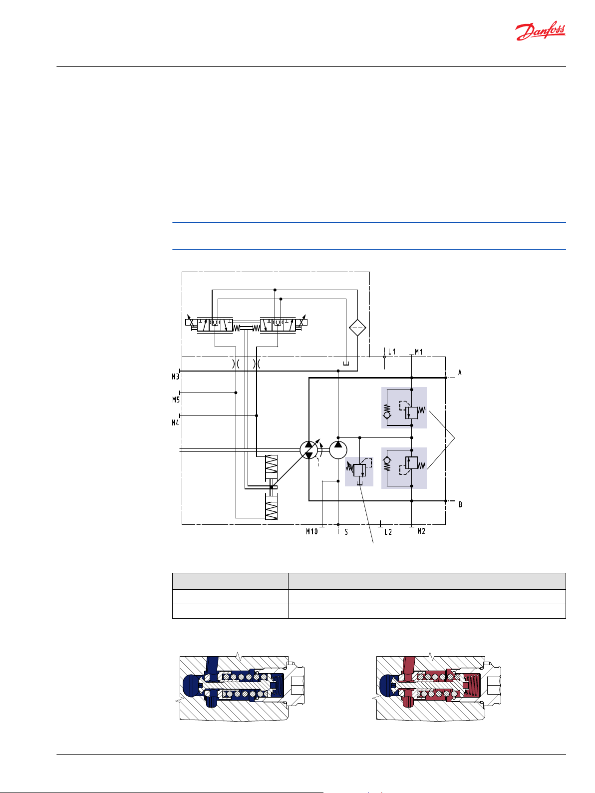
High pressure relief valve (HPRV) and charge check valve
The TMP pumps are equipped with a combination high pressure relief and charge check valve. The highpressure relief function is a dissipative pressure control valve for the purpose of limiting excessive system
pressures. The charge check function acts to replenish the low-pressure side of the working loop with
charge oil. Each side of the transmission loop has a dedicated HPRV valve that is non-adjustable with a
factory set pressure. When system pressure exceeds the factory setting of the valve, oil is passed from the
high pressure system loop, into the charge gallery, and into the low pressure system loop via the charge
check.
The pump order code allows for different pressure settings to be used at each system port.
HPRVs are set at low flow condition. Any application or operating condition which leads to elevated HPRV
flow will cause a pressure rise with flow above the valve setting. Consult factory for application.
System schematic, single pump
©
Danfoss | July 2017 L1010109 | AX00000131en-US0203 | 11
Pressures marked on HPRV valve
Mark Pressure bar [psi]
28 280 [4061]
42 420 [6092]
HPRV and check valve in charging mode HPRV and check valve in relief mode
Page 12
Service Manual
TMP Transit Mixer Axial Piston Pump, Size 070/089
Operation
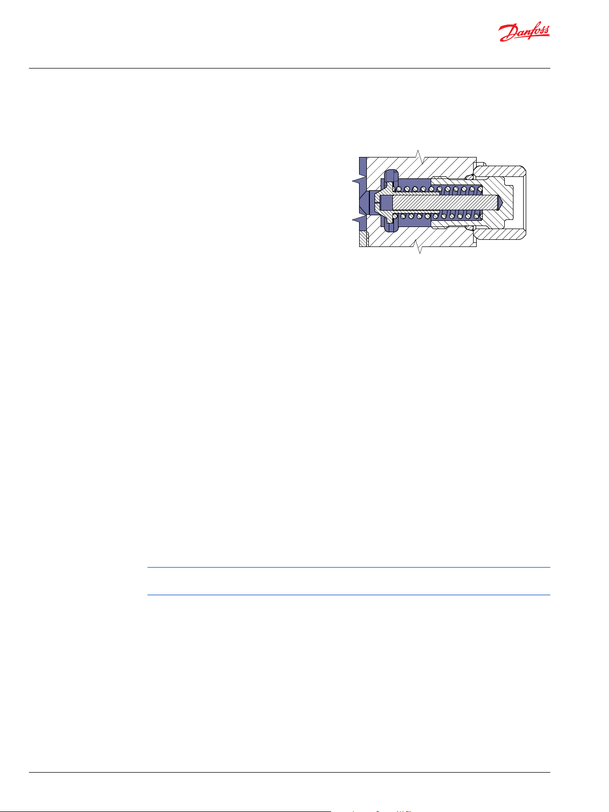
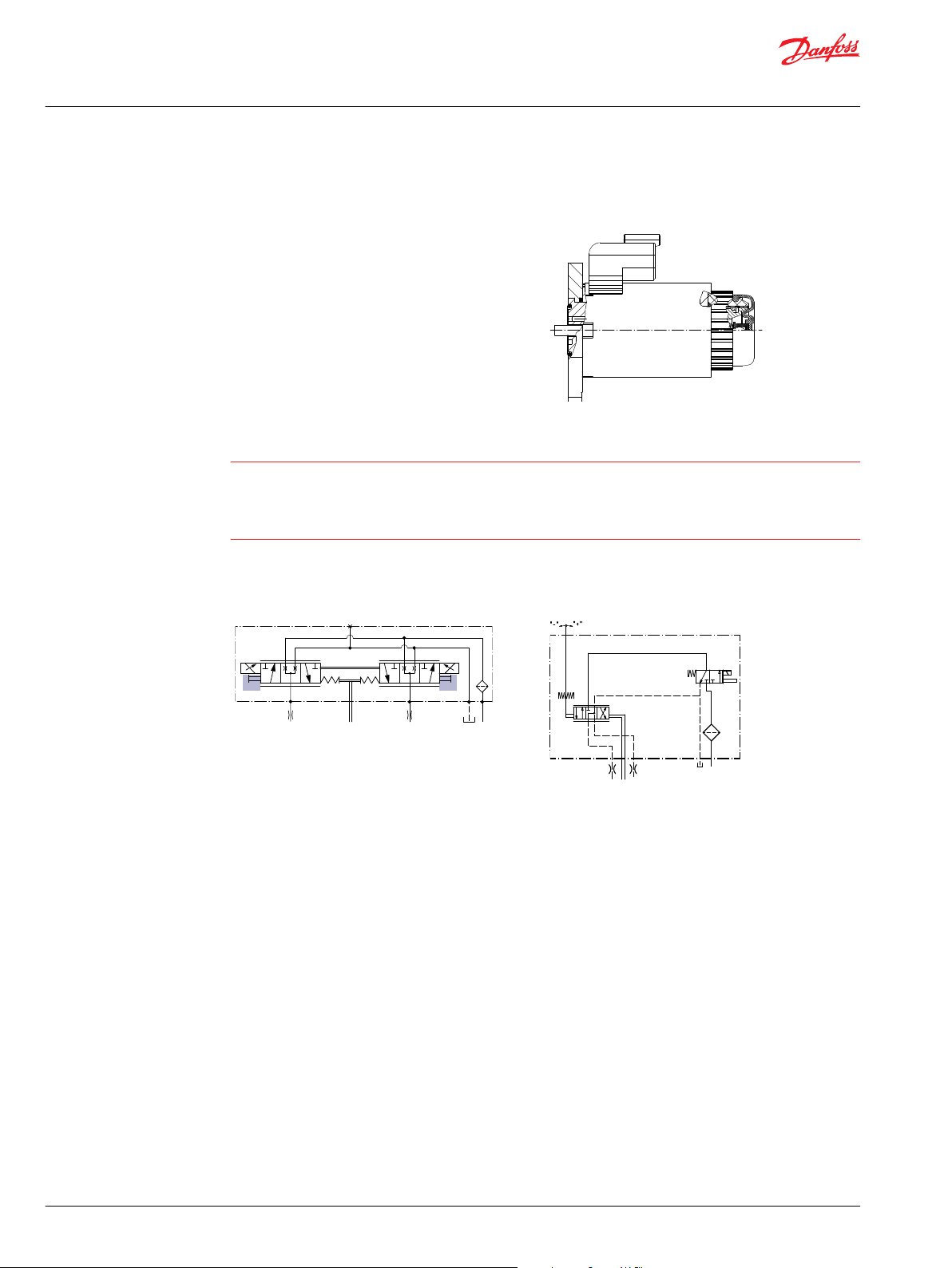
Charge pressure relief valve (CPRV)
The charge pressure relief valve maintains charge
pressure at a designated level above case pressure.
The charge pressure relief valve is a direct acting poppet
valve which opens and discharges fluid to the pump case
when pressure exceeds a designated level. Standard level
setting is ∆p = 21 ± 1.1 bar [304 ± 16 psi] with the pump
running at 1500 min-1 (rpm) and flow = 23.8 - 29.5 l/min
[ 6.3 - 7.8 US gal/min].
Typical charge pressure increase is 2 bar per 10 l/min [29
psi per 2.64 US gal/min].
Electrical Displacement Control (EDC)
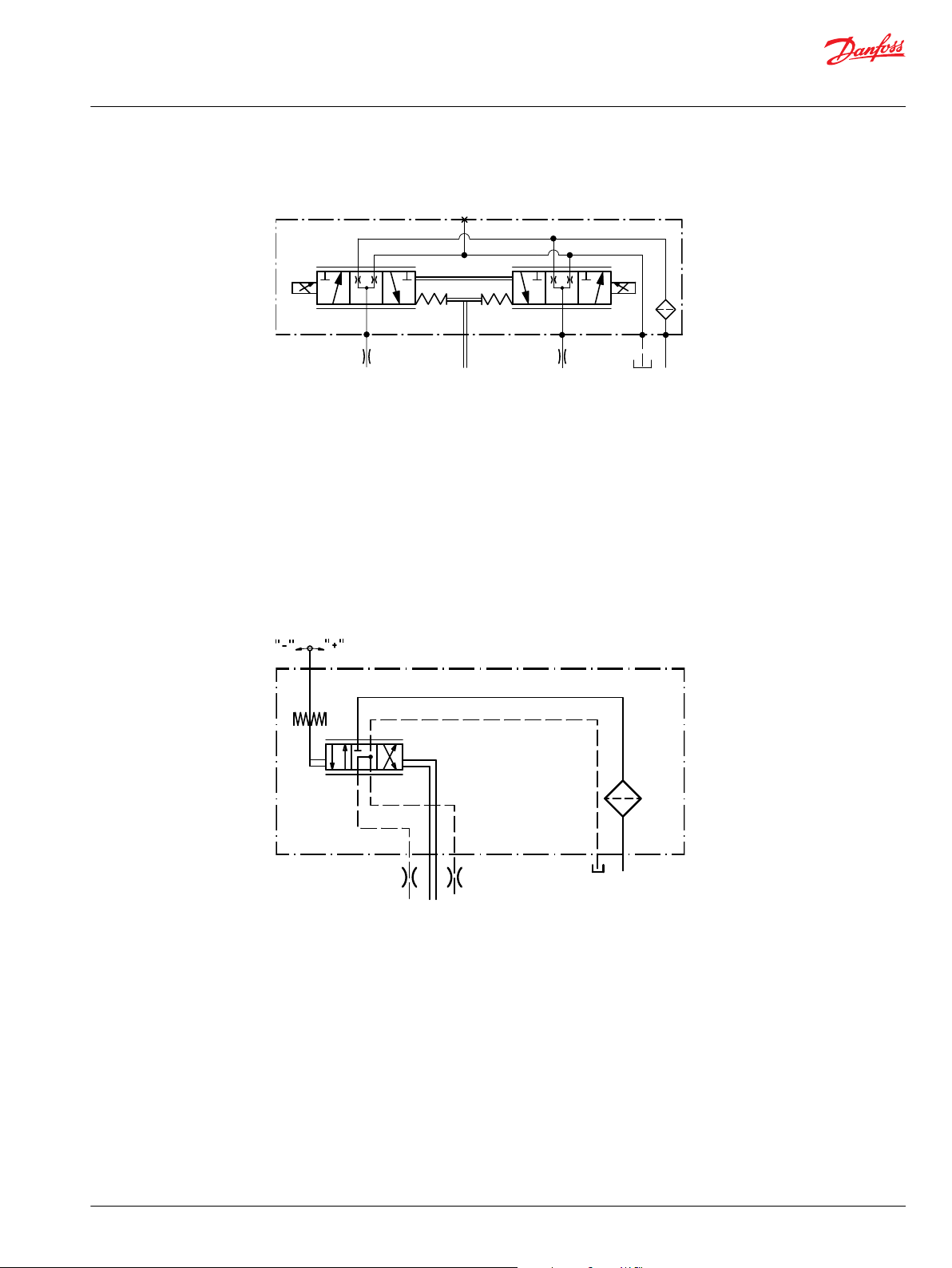
EDC Principle
The Electrical Displacement Control (EDC) consists of proportional solenoids on each side of a threeposition, four-way porting spool. The proportional solenoid applies a force to the spool, which ports
hydraulic fluid to either side of the servo piston. Differential pressure across the servo piston rotates the
swashplate, changing the pump's displacement from full displacement in one direction to full
displacement in the opposite direction.
EDC operation
EDC's are current driven controls requiring a Pulse Width Modulated (PWM) signal. Pulse width
modulation allows more precise control of current to the solenoids. The PWM signal causes the solenoid
pin to push against the porting spool, which pressurizes one end of the servo piston, while draining the
other. Pressure differential across the servo piston moves the swashplate. A swashplate feedback link,
opposing control links, and a linear spring provide swashplate position force feedback to the solenoid.
The control system reaches equilibrium when the position of the swashplate spring feedback force
exactly balances the input command solenoid force from the operator. As hydraulic pressures in the
operating loop change with load, the control assembly and servo/swashplate system work constantly to
maintain the commanded position of the swashplate.
The EDC incorporates a positive neutral dead-band as a result of the control spool porting, spring preload
from the servo piston assembly, and the linear control spring. Once the neutral threshold current is
reached, the swashplate position becomes directly proportional to the control current. To minimize the
effect of the control neutral deadband, we recommended the transmission controller or operator input
device incorporate a jump up current.
Charge pressure relief valve (CPRV)
The neutral position of the control spool does provide a positive preload pressure to each end of the
servo piston assembly.
When the control input signal is either lost or removed, or if there is a loss of charge pressure, the springloaded servo piston automatically returns the pump to neutral position.
The EDC is a displacement (flow) control. Pump swashplate position is proportional to the input
command and therefore vehicle or load speed (excluding influence of efficiency), is dependent only on
the prime mover speed or motor displacement.
12 | © Danfoss | July 2017 L1010109 | AX00000131en-US0203
Page 13
Feedback from swash-plate
PT
M14
C1 C2
Feedback from swasch plate
T P
N
Service Manual
TMP Transit Mixer Axial Piston Pump, Size 070/089
Operation
EDC schematic diagram
Manual Displacement Control (MDC)
MDC principle
The Manual Displacement Control (MDC) consists of a lever with eccentric shaft centre of a threeposition, four-way porting spool. The eccentric shaft applies a force input to the spool, which ports
hydraulic pressure to either side of a double acting servo piston.
Differential pressure across the servo piston rotates the swash plate, changing the pump`s displacement
from full displacement in one direction to full displacement in the opposite direction.
MDC Schematic (P005571E)
MDC with control cut off (CCO)
If solenoid is loaded by voltage directly from truck battery 24 to 32 V pump work in normal mode if the
electric circuit will by switch off pump will go immediately to 0 position.
©
Danfoss | July 2017 L1010109 | AX00000131en-US0203 | 13
Page 14
P003 204
W
Feedback from swash-plate
PT
M14
C2
C1
Feedback from swasch plate
T P
N
Service Manual
TMP Transit Mixer Axial Piston Pump, Size 070/089
Operation
Manual Over Ride (MOR)
All controls are available with a Manual Over Ride (MOR)
either standard or as an option for temporary actuation of
MOR
the control to aid in diagnostics.
The vehicle or device must always be in a ‘safe’ condition
(i.e. vehicle lifted off the ground) when using the MOR
function.
The MOR plunger has a 4 mm diameter and must be
manually depressed to be engaged.
Depressing the plunger mechanically moves the control
spool which allows the pump to go on stroke.
The MOR should be engaged anticipating a full stroke
response from the pump.
Warning
An O-Ring seal is used to seal the MOR plunger where initial actuation of the function will require a force
of 45 N to engage the plunger. Additional actuations typically require a threshold force of 12 N to move
the MOR plunger. Force required to keep the pump at full stroke is typically 51 N. Proportional control of
the pump using the MOR should not be expected.
Refer to control flow table for the relationship of solenoid to direction of flow.
MOR schematic diagram (EDC shown)
MOR schematic diagram (MDC shown)
14 | © Danfoss | July 2017 L1010109 | AX00000131en-US0203
Page 15

W
Service Manual
TMP Transit Mixer Axial Piston Pump, Size 070/089
Operating Parameters
Overview
This section defines the operating parameters and limitations for TMP pumps with regard to input speeds
and pressures. For actual parameters, refer to the operating parameters for each displacement.
Input Speed
Minimum speed is the lowest input speed recommended during engine idle condition. Operating below
minimum speed limits the pump's ability to maintain adequate flow for lubrication and power
transmission.
Rated speed is the highest input speed recommended at full power condition. Operating at or below
this speed generally yields satisfactory product life.
Maximum speed is the highest operating speed permitted. Exceeding maximum speed reduces product
life and can cause loss of hydrostatic power and braking capacity. Never exceed the maximum speed
limit under any operating conditions.
When determining speed limits for a particular application see Danfoss publication Pressure and speed
limits.
Warning
System Pressure
Charge Pressure
Unintended vehicle or machine movement hazard. Exceeding maximum speed may cause a loss of
hydrostatic drive line power and braking capacity. You must provide a braking system, redundant to the
hydrostatic transmission, sufficient to stop and hold the vehicle or machine in the event of hydrostatic
drive power loss.
System pressure is the differential pressure between system ports A & B. It is the dominant operating
variable affecting hydraulic unit life. High system pressure, which results from high load, reduces
expected life. Hydraulic unit life depends on speed and normal operating—or weighted average—
pressure that you can only determine from a duty cycle analysis.
Applied pressure is the chosen application pressure in the order code for the pump. This is the pressure
at which the drive line generates maximum pull or torque in the application.
Rated pressure is the design pressure for the pump. Applications with applied pressures at or below this
pressure should yield satisfactory unit life given proper component selection.
Maximum pressure (peak) is the highest intermittent pressure allowed under any circumstances.
Applications with applied pressures between rated and maximum require factory approval with
complete application, duty cycle, and life expectancy analysis.
All pressure limits are differential pressures referenced to low loop (charge) pressure. Subtract low loop
pressure from gauge readings to compute the differential.
An internal charge relief valve regulates charge pressure. The internal charge pump supplies the control
with pressure to operate the swashplate and to maintain a minimum pressure in the low side of the
transmission loop.
Minimum charge pressure is the lowest pressure safe working conditions allow in the system loop.
Minimum control pressure requirements are a function of speed, pressure, and swashplate angle, and
may be higher than the minimum charge pressure shown in the technical specifications.
Maximum charge pressure is the highest charge pressure the charge relief adjustment allows, and
which provides normal component life. You can use elevated charge pressure as a secondary means to
reduce the swashplate response time.
©
Danfoss | July 2017 L1010109 | AX00000131en-US0203 | 15
Page 16

W
Service Manual
TMP Transit Mixer Axial Piston Pump, Size 070/089
Operating Parameters
The charge pressure setting listed in the order code is the set pressure of the charge relief valve with the
pump in neutral, operating at 1500 min-1 (rpm), and with a fluid viscosity of 32 mm2/sec [150 SUS]. The
charge pressure setting is referenced to case pressure (the differential pressure above case pressure).
Charge inlet pressure
At normal operating temperature charge inlet pressure must not fall below rated charge inlet pressure.
Minimum charge inlet pressure is only allowed at cold start conditions. In some applications, you may
need to warm up the fluid (start the prime mover without using the vehicle/machine functions) before
moving the vehicle or operating the machine.
Case Pressure
Do not exceed rated case pressure under normal operating conditions. During cold start, keep case
pressure below maximum intermittent case pressure. Size drain plumbing accordingly.
Warning
Possible component damage or leakage. Operation with case pressure in excess of stated limits may
damage seals, gaskets, and/or housings, causing external leakage. This condition may also affect
performance since charge and system pressure are referenced to case pressure.
Temperature and Viscosity
General specification
Temperature
High temperature limits apply at the hottest point in the transmission loop, which is normally the motor
case drain. Ensure the system generally runs at or below the rated temperature.
The maximum intermittent temperature is based on material properties. Never exceed it!
Cold oil will generally not affect the durability of the transmission components, but it may affect the
ability of oil to flow and transmit power: therefore ensure temperatures remain 16 °C [30 °F] above the
pour point of the hydraulic fluid. Minimum temperature relates to the physical properties of component
materials. Size heat exchangers to keep the fluid within these limits. Danfoss recommends testing to
verify that these temperature limits are not exceeded.
Viscosity
For maximum efficiency and bearing life, ensure the fluid viscosity remains in the recommended range.
Minimum viscosity should be encountered only during brief occasions of maximum ambient
temperature and severe duty cycle operation.
Maximum viscosity should be encountered only at cold start.
General specifications
Design
Direction of rotation
Axial piston pump cradle swashplate design with variable displacement
Clockwise, counterclockwise
16 | © Danfoss | July 2017 L1010109 | AX00000131en-US0203
Page 17

C
Service Manual
TMP Transit Mixer Axial Piston Pump, Size 070/089
Operating Parameters
General specifications (continued)
Pipe connections
Recommended
installation position
Caution
The front shaft seal must not be exposed to oil pressure from outside of the unit.
Boundary position of the MDC lever must be fixed by hard stop on the customer actuation mechanism in
order to prevent any damages of MDC.
Physical Properties
Technical data
Features Unit Size
Displacement maximum cm
Oil volume l [US gal] 2 [0.53] 2 [0.53]
Mounting flange SAE ISO 3019/1 flange 127-4 (SAE C), M12x1,75
Input shaft Spline shaft SAE, 21 teeth, pitch = 16/32
Auxiliary mounting flange with metric fasteners,
shaft splines
Suction port ISO 6149-1 – M42x2 (O-ring boss)
Main port configuration Twin ports SAE J518b Size 1, with metric screws M12
Case drain ports L1, L2 ISO 6149-1 – M22x1,5 (O-ring boss)
Other ports ISO 6149-1 straight thread O-ring boss.
Main pressure ports: ISO split flange boss
Remaining ports: ISO straight thread O-ring boss
Pump installation position is discretionary; however the recommended control position is on
the top. The housing must always be filled with hydraulic fluid.
Pump shaft connection is discretionary, however it is strongly recommended to use rubber
coupling if pump is driven via “cardan” shaft.
Correct installation has a significant influence on a life time of the pump.
070 089
3
[in3]
Spline shaft SAE, 23 teeth, pitch = 16/32
Coupling for Cardan, 23 teeth (only with spline shaft SAE, 23 teeth, pitch = 16/32)
SAE A, 11 teeth, pitch = 16/32
SAE B, 13 teeth, pitch = 16/32
SAE B-B, 15 teeth, pitch = 16/32
See Port Locations and Gauge Installation on page 19.
68.3
[4.17]
89.0
[5.43]
Operating parameters
Operating parameters, size 070 / 089
Features Unit Sizes 070 / 089
Input speed Minimum
Rated
Maximum
System pressure Max. working pressure
Maximum pressure
Minimum pressure
©
Danfoss | July 2017 L1010109 | AX00000131en-US0203 | 17
min-1 (rpm)
bar [psi]
500
2500
2900
420 [6090]
450 [6525]
10 [145]
Page 18

Service Manual
TMP Transit Mixer Axial Piston Pump, Size 070/089
Operating Parameters
Operating parameters, size 070 / 089 (continued)
Features Unit Sizes 070 / 089
Charge pressure Minimum
Maximum
Control pressure Minimum (at corner
power for EDC)
Maximum
Charge pump inlet
pressure
Case pressure Rated
Lip seal external pressure
Rated
Minimum (cold start)
Maximum
Maximum
Maximum
bar [psi]
bar [psi]
bar (absolute)
[in Hg vacuum]
bar [psi]
bar [psi]
17 [247]
30 [436]
21 [305]
30 [435]
0.7 [9]
0.2 [24]
4 [58]
3 [44]
5 [73]
0.4 [5.8]
Fluid Specifications
Fluid specifications
Features Unit Sizes 070 / 089
Viscosity Intermittent
1
mm2/s [SUS] 5 [42]
Minimum 7 [49]
Recommended range 12-80 [66-370]
Maximum 1600 [7500]
Temperature
2
range
Minimum (cold start)
Recommended range 60-85 [140-185]
3
°C [°F] -40 [-40]
Rated 104 [220]
1
115 [240]
Filtration (recommended
minimum)
Maximum intermittent
Cleanliness per ISO 4406 22/18/13
Efficiency (charge pressure filtration) β-ratio β15-20 = 75 (β10 ≥ 10)
Efficiency (suction and return line filtration) β35-45 = 75 (β10 ≥ 2)
Recommended inlet screen mesh size µm 100 – 125
1
Intermittent = Short term t < 1 min per incident and not exceeding 2 % of duty cycle based load-life
2
At the hottest point, normally case drain port
3
Cold start = Short term t < 3 min, p ≤ 50 bar [725 psi], n ≤ 1000 min-1(rpm)
Ratings and data are based on operation with premium petroleum-based hydraulic fluids containing
oxidation, rust, and foam inhibitors.
18 | © Danfoss | July 2017 L1010109 | AX00000131en-US0203
Page 19

W
Service Manual
TMP Transit Mixer Axial Piston Pump, Size 070/089
Fluid and Filter Maintenance
Fluid and filter recommendations
To ensure optimum life, perform regular maintenance of the fluid and filter. Contaminated fluid is the
main cause of unit failure. Take care to maintain fluid cleanliness when servicing.
Check the reservoir daily for proper fluid level, the presence of water, and rancid fluid odor. Fluid
contaminated by water may appear cloudy or milky or free water may settle in the bottom of the
reservoir. Rancid odor indicates the fluid has been exposed to excessive heat. Change the fluid and
correct the problem immediately if these conditions occur.
Inspect vehicle for leaks daily. Change the fluid and filter per the vehicle/machine manufacturer's
recommendations or at intervals shown in the table. We recommend first fluid change at 500 hours.
Fluid and Filter Change Interval
Reservoir type Max oil change interval
Sealed 2000 hours
Breather 500 hours
High temperatures and pressures will result in accelerated fluid aging. More frequent fluid changes may
be required.
Change the fluid more frequently if it becomes contaminated with foreign matter (dirt, water, grease,
etc.) or if the fluid is subjected to temperature levels greater than the recommended maximum. Dispose
of used hydraulic fluid properly. Never reuse hydraulic fluid.
Change filters with the fluid or when the filter indicator shows it’s necessary. Replace all fluid lost during
filter change.
For detailed filtration information, see Danfoss publication 520L0463 Fluids and Filtration. For
information on biodegradable fluids see Danfoss publication 520L0465 Biodegradable Hydraulic Fluids.
Warning
Hydraulic fluid contains hazardous material. Avoid contact with hydraulic fluid. Always dispose of used
hydraulic fluid according to state and federal environmental regulations.
Port Locations and Gauge Installation
The following table and drawings show the port locations and gauge sizes needed. When testing system
pressures, calibrate pressure gauges frequently to ensure accuracy. Use snubbers to protect gauges.
Port Information
Identifier Port Description Size Wrench size Gauge size,
bar [psi]
L1, L2 Case drain ports M22x1.5 10 mm internal hex 10 [100]
M1, M2, M4, M5 System A/B, charge and servo gage M12x1.5 6 mm internal hex 50 [1000]
M10 Charge pump inlet pressure M12x1.5 6 mm internal hex 50 [1000]
S Charge inlet port M42x2.0 10 [100]
©
Danfoss | July 2017 L1010109 | AX00000131en-US0203 | 19
Page 20

Gauge port M2
System pressure port B
M12 x 1.5
Gauge port M1
System pressure port A
M12 x 1.5
Gauge port M4
Servo pressure
M12 x 1.5
Gauge port M5
Servo pressure
M12 x 1.5
Gauge port M10
Charge pump inlet pressure
M12 x 1.5
Gauge port M3
Charge pressure
M12 x 1.5
O-ring plug
7/16-20 UNF
use for air bleed when filling pump
(only by EDC)
Case drain Port L2
M22 x 1.5
O-ring boss
System port B
Charge pump inlet S
M42 x 2
System port A
Case drain Port L1
M22 x 1.5
Service Manual
TMP Transit Mixer Axial Piston Pump, Size 070/089
Fluid and Filter Maintenance
Port locations
P005443E
20 | © Danfoss | July 2017 L1010109 | AX00000131en-US0203
Page 21

W
C
Service Manual
TMP Transit Mixer Axial Piston Pump, Size 070/089
Initial Startup Procedures
General
Follow this procedure when starting-up a new pump installation or when restarting an installation in
which the pump has been removed and re-installed on a machine. Ensure pump has been thoroughly
tested on a test stand before installing on a machine. Prior to installing the pump, inspect for damage
that may have occurred during shipping.
Warning
Unintended movement of the machine or mechanism may cause injury to the technician or bystanders.
To protect against unintended movement, secure the machine or disable/disconnect the mechanism
while servicing.
Start-Up procedure
1. Ensure that the machine hydraulic oil and system components (reservoir, hoses, valves, fittings, and
heat exchanger) are clean and free of any foreign material.
2. Install new system filter element(s) if necessary. Check that inlet line fittings are properly tightened
and there are no air leaks.
3. Install the pump. Install a 50 bar [1000 psi] gauge in the charge pressure gauge port M
4. Fill the housing by adding filtered oil in the upper case drain port. If the control is installed on top,
open the construction plug in the top of the control to assist in air bleed.
5. Fill the reservoir with hydraulic fluid of the recommended type and viscosity. Use a 10-micron filler
filter. Fill inlet line from reservoir to pump.
6. Disconnect the pump from all control input signals.
7. Close construction plug removed in Step 4.
Caution
After start-up the fluid level in the reservoir may drop due to system components filling. Damage to
hydraulic components may occur if the fluid supply runs out. Ensure reservoir remains full of fluid
during start-up.
Air entrapment in oil under high pressure may damage hydraulic components. Check carefully for
inlet line leaks.
Do not run at maximum pressure until system is free of air and fluid has been thoroughly filtered.
8. Use a common method to disable the engine to prevent it from starting. Crank the starter for several
seconds. Do not to exceed the engine manufacturer's recommendation. Wait 30 seconds and then
crank the engine a second time as stated above. This operation helps remove air from the system
lines. Refill the reservoir to recommended full oil level.
9. When the gauge begins to register charge pressure, enable and start engine. Let the engine run for a
minimum of 30 seconds at low idle to allow the air to work itself out of the system. Check for leaks at
all line connections and listen for cavitation. Check for proper fluid level in reservoir.
10. When adequate charge pressure is established (as shown in model code), increase engine speed to
normal operating rpm to further purge residual air from the system.
11. Shut off engine. Connect pump control signal. Start engine, checking to be certain pump remains in
neutral. Run engine at normal operating speed and carefully check for forward and reverse control
operation.
12. Continue to cycle between forward and reverse for at least five minutes to bleed all air and flush
system contaminants out of loop.
Normal charge pressure fluctuation may occur during forward and reverse operation.
13. Check that the reservoir is full. Remove charge pressure gauge.
The pump is now ready for operation.
©
Danfoss | July 2017 L1010109 | AX00000131en-US0203 | 21
Page 22

C
W
W
C
W
Service Manual
TMP Transit Mixer Axial Piston Pump, Size 070/089
Troubleshooting
Overview
This section provides general steps to follow if you observe undesirable system conditions. Follow the
steps listed until you solve the problem. Some of the items are system specific. We reference the section
in this manual if more information is available. Always observe the safety precautions listed in Safety
Precautions and precautions related to your specific equipment.
Safety Precautions
Caution
High inlet vacuum causes cavitation which can damage internal pump components.
Warning
Escaping hydraulic fluid under pressure can have sufficient force to penetrate your skin causing serious
injury and/or infection. Relieve pressure in the system before removing hoses, fittings, gauges, or
components.
Warning
Unintended movement of the machine or mechanism may cause injury to the technician or bystanders.
To protect against unintended movement, secure the machine or disable/disconnect the mechanism
while servicing.
Caution
Contamination can damage internal components and void the manufacturer's warranty. Take
precautions to ensure system cleanliness when removing and reinstalling system lines
Warning
Hydraulic fluid contains hazardous material. Avoid contact with hydraulic fluid. Always dispose of used
hydraulic fluid according to state, and federal environmental regulations.
Electrical Troubleshooting (TMP EDC)
Item Description Action
Control operates pump in one
direction only.
No pump function No power to controller Restore power to controller.
Erratic pump function Electrical connection to pump is bad. Disconnect connection, check wires, reconnect wires.
Control coil failure Measure resistance at coil pins. Resistance should be 14.20 ohms (24V) or
3.66 ohms (12V) at 20°C [70°F]. Replace coil
If available, use manual override to check proper pump operation and verify electrical problem.
System Operating Hot
Item Description Action
Oil level in reservoir. Insufficient hydraulic fluid will not meet cooling demands
of system.
Heat exchanger. Heat exchanger is not sufficiently cooling the system. Check air flow and input air temperature for heat
22 | © Danfoss | July 2017 L1010109 | AX00000131en-US0203
Fill reservoir to proper level.
exchanger. Clean, repair or replace heat exchanger.
Page 23

Service Manual
TMP Transit Mixer Axial Piston Pump, Size 070/089
Troubleshooting
Item Description Action
Charge pressure. Low charge pressure will overwork system. Measure charge pressure. Inspect and adjust or replace
charge relief valve. Inspect charge pump. Repair or replace
charge pump.
Charge pump inlet vacuum. High inlet vacuum will overwork system. A dirty filter will
increase the inlet vacuum. Inadequate line size will restrict
flow.
System relief pressure
settings
System pressure. Frequent or long term operation over system relief setting
If the system relief valves are worn, contaminated, or valve
settings are too low, the relief valves will be overworked.
will create heat in system.
Neutral Difficult or Impossible to Find
Item Description Action
Input to pump control Input to control module is operating
improperly.
Neutral Neutral set improperly Shunt servo gauge ports (M4 and M5) together with
Check charge inlet vacuum. If high, inspect inlet filter and
replace as necessary. Check for adequate line size, length or
other restrictions.
Verify settings of high pressure relief valves and replace
valves as necessary.
Measure system pressure. If pressure is too high, reduce
loads.
Disconnect input and check to see if pump comes back to
neutral. If Yes, input fault, replace/repair external controller.
If No, go to next step.
external hose and see if pump comes back to neutral. If Yes:
Control neutral improperly set (see page 31-34) If neutral
still impossible to set, balance swashplate (see Mechanical
neutral adjustment, page 35-37). If you still cannot set
neutral, replace control.
System Will Not Operate in Either Direction
Item Description Action
Oil level in reservoir. Insufficient hydraulic fluid to supply system loop. Fill reservoir to proper level.
Pump control orifices Control orifices are blocked. Clean control orifices.
Pump control screens Control screens are blocked. Replace control screens. Only a Danfoss Authorized Service
Center may remove the unit's endcap without voiding the
warranty.
Low charge pressure with
pump in neutral
Low charge pressure with
pump in stroke
Pump charge relief valve A pump charge relief valve that is leaky, contaminated, or
Charge pump inlet filter A clogged filter will under supply system loop. Inspect filter and replace if necessary.
Charge pump A malfunctioning charge pump will provide insufficient
System pressure Low system pressure does not provide enough power to
High pressure relief valve Defective high pressure relief valve cause system pressure
Input to control Input operating improperly Repair/replace control.
Low charge pressure insufficient to recharge system loop. Measure charge pressure with the pump in neutral. If
pressure is low, go to Pump charge relief valve.
Low charge pressure resulting from elevated loop leakage.
Insufficient control pressure to hold pump in stroke.
set too low will depressurize the system.
charge flow.
move load.
to be low.
Deadhead the pump to isolate it from the motor.With
pump in partial stroke and engaged for only a few seconds,
check pump charge pressure. Low charge pressure
indicates a malfunctioning pump. Continue to next step.
Good charge pressure indicates a malfunctioning motor or
other system component. Check motor charge relief
operation (if present).
Adjust or replace pump charge relief valve as necessary.
Repair or replace the charge pump.
Measure system pressure. Continue to next step.
Repair or replace high pressure relief valve.
©
Danfoss | July 2017 L1010109 | AX00000131en-US0203 | 23
Page 24

Service Manual
TMP Transit Mixer Axial Piston Pump, Size 070/089
Troubleshooting
System Noise or Vibration
Item Description Action
Reservoir oil level Low oil level leads to cavitation. Fill reservoir.
Aeration of the oil/pump
inlet vacuum
Cold oil If oil is cold, it may be too viscous for proper function
Pump inlet vacuum High inlet vacuum causes noise/cavitation. Check that inlet line is not restricted and is of proper size.
Shaft couplings A loose shaft coupling will cause excessive noise. Replace loose shaft coupling..
Shaft alignment Misaligned shafts create noise. Align shafts.
Charge/system relief valves Unusual noise may indicate sticking valves and possible
Sluggish System Response
Item Description Action
Oil level in reservoir Low oil level causes sluggish response. Fill reservoir.
High pressure relief valves settings Incorrect pressure settings affects system reaction time. Adjust or replace high pressure relief valves.
Low prime mover speed Low engine speed reduces system performance. Adjust engine speed.
Charge pressure Incorrect pressure affects system performance. Measure and adjust charge pressure relief or
Air in system Air in system produces sluggish system response. Fill tank to proper level. Cycle system slowly for
Contaminated control orifices Control orifices are plugged. Clean control orifices.
Contaminated control screens Supply screen is plugged. Replace control screens.
Pump inlet vacuum Inlet vacuum is too high resulting in reduced system
Air in system decreases efficiency of units and controls.
Excessive noise, foaming oil, and hot oil all indicate air in
system.
causing pump cavitation.
contamination.
pressure.
Find location where air is entering into the system and
repair. Check that inlet line is not restricted and is proper
size.
Allow the oil to warm up to its normal operating
temperature with engine at idle speed.
Check filter and bypass switch.
Clean/replace valves and test pump.
replace charge pump.
several minutes to remove air from system.
Measure charge inlet vacuum. Inspect line for
proper sizing. Replace filter. Confirm proper bypass
operation.
Transmission Operates Normally in One Direction Only
Item Description Action
Input to pump control. Input to control module is operating improperly. Check control input and repair or replace as necessary.
Control orifices Control orifice(s) are blocked. Clean control orifices.
Control screens Control screen(s) are blocked. Replace control screens.
Exchange high pressure
relief valves
Servo pressure low or
decaying
Exchanging the high pressure relief valves will show if
the problem is related to the valve function.
Damaged servo seals may prevent servo piston from
stroking the pump.
If the problem changes direction, replace the valve that does not
operate correctly.
Check for torn/missing servo seals. Replace and retest. Only a
Danfoss Authorized Service Center may remove the servo piston
without voiding the warranty.
24 | © Danfoss | July 2017 L1010109 | AX00000131en-US0203
Page 25

C
Case drain port L2
Servo pressure gauge port M4, M5
Adjustment screw
13 mm
Locknut
27 mm
65 N•m [48 lbf•ft]
Optional construction port
0 - 10 bar [0 - 100 psi]
M22x1.5
40 N•m [29.5 lbf•ft]
0 - 10 bar [0 - 100 psi]
3/16 in
12 N•m [9 lbf•ft]
0 - 50 bar [0 - 1000 psi]
M12x1.5
21 N•m [15.5 lbf•ft]
Charge pressure gauge port M3
0 - 50 bar [0 - 1000 psi]
M12x1.5
21 N•m [15.5 lbf•ft]
Locknut
M40x1.5
80 N•m [59 lbf•ft]
Service Manual
TMP Transit Mixer Axial Piston Pump, Size 070/089
Adjustments
Pump Adjustment
This section offers instruction on inspection and adjustment of pump components. Read through the
entire topic before beginning a service activity. Refer to Port Locations and Gauge Installation on page 19,
for location of gauge ports and suggested gauge size.
Standard Procedures
Caution
Contamination can damage internal components and void your warranty. Take precautions to ensure
system cleanliness when removing and reinstalling system lines.
1. With the prime mover off, thoroughly clean the outside of the pump.
2. If removing the pump, tag each hydraulic line. When you disconnect hydraulic lines, cap them and
plug each open port to prevent contamination.
3. Ensure the surrounding area is clean and free of contaminants like dirt and grime.
4. Inspect the system for contamination.
5. Check the hydraulic fluid for signs of contamination: oil discoloration, foam in the oil, sludge, or metal
particles.
6. If there are signs of contamination in the hydraulic fluid, replace all filters and drain the hydraulic
system. Flush the lines and refill the reservoir with the correct filtered hydraulic fluid.
7. Before re-installing the pump, test for leaks.
Charge Pressure Relief Valve Adjustments
This procedure explains how to check and adjust the charge pressure relief valve.
Charge Pressure Adjustment (P005619E)
Listed pressures assume a pump speed of 1500 min¯¹ (rpm). At higher pump speeds (with higher charge
flows) the charge pressure will rise over the rated setting.
©
Danfoss | July 2017 L1010109 | AX00000131en-US0203 | 25
Page 26

W
Servo pressure gauge port M4, M5
Adjustment screw
4 mm
Locknut
13 mm
12 N•m [9 lbf•ft]
0 - 50 bar [0 - 1000 psi]
M12x1.5
21 N•m [15.5 lbf•ft]
D060 D015
Service Manual
TMP Transit Mixer Axial Piston Pump, Size 070/089
Adjustments
1. Install a 50 bar [1000 psi] pressure gauge in charge pressure gauge port M3. Install a 10 bar [100 psi]
gauge at case drain port L1 or L2. Operate the system with the pump in neutral (zero displacement)
when measuring charge pressure.
2. Nominal charge relief valve settings 20.3 - 25 bar [294 - 326 psi] (refer to model code located on serial
number plate). This pressure assumes 1500 min-1 (rpm) pump speed and a reservoir temperature of
50°C [120°F], and is referenced to case pressure.
3. Loosen the locknut and turn the adjusting screw clockwise to increase the setting; counterclockwise
to decrease it. Approximate adjustment per turn is 2.4 bar.
4. While holding the adjusting screw, torque locknut to 65 N•m [48 lbf•ft].
EDC neutral adjustment
All functions of the Electric Displacement Control (EDC), are preset at the factory. If necessary, adjust the
pump to neutral with the pump running on a test stand or on the vehicle/machine with the prime mover
operating. If adjustment fails to give satisfactory results, you may need to replace the control or coils. See
Removal on page 35 for details.
Warning
Unintended movement of the machine or mechanism may cause injury to the technician or bystanders.
To protect against unintended movement, secure the machine or disable/disconnect the mechanism
while servicing.
Adjustment of the EDC is very sensitive. Be sure to hold the hex wrench steady while loosening the
locknut. Total adjustment is less than 120 degrees.
EDC Control Adjustment (P005437E)
26 | © Danfoss | July 2017 L1010109 | AX00000131en-US0203
Page 27

Solenoid shaft
Feedback pin
Adjusting
screw
(cam)
P106 046E
Maximum
adjustment
less than 120°
Control spool
Service Manual
TMP Transit Mixer Axial Piston Pump, Size 070/089
Adjustments
1. Install a 50 bar [1000 psi] gauge in each of the two servo gauge ports (M4 and M5). Disconnect the
external control input (electrical connections) from the control. Start the prime mover and operate at
normal speed.
2. Use a 4 mm internal hex wrench to hold the neutral adjusting screw (D015) stationary while
loosening the locknut (D060) with a 13 mm wrench.
3. Observe pressure gauges. If necessary, turn adjusting screw (D015) to reduce pressure differential.
4. Rotate the neutral adjusting screw (D015) clockwise until the pressure increases on the gauge. Note
the angular position of the wrench. Then rotate the neutral adjusting screw counterclockwise until
the pressure increases by an equal amount on the other gauge. Again note the angular position of
the wrench.
5. Rotate the neutral adjusting screw clockwise half the distance between the wrench positions noted
above. The gauges should read the same pressure, indicating that the control is in its neutral position.
6. Hold the neutral adjusting screw stationary and tighten the locknut (D060). Torque to 10 N•m [7.5
lbf•ft]. Do not over torque the nut.
7. When the neutral position is set, stop the prime mover, remove the gauges, and install the gauge
port plugs. Reconnect the external control input.
Neutral adjustment (EDC, bottom view)
Illustration shows how cam on adjusting pin rotates to
adjust for neutral position after pump is re-installed.
A small pressure differential of 1.5 bar [22 psi] or less is
acceptable. Zero differential is usually not possible.
MDC Control Neutral Adjustment
All functions of the Mechanical Displacement Control (MDC), are preset at the factory. If necessary, adjust
©
Danfoss | July 2017 L1010109 | AX00000131en-US0203 | 27
the pump to neutral with the pump running on a test stand or on the vehicle/machine with the prime
mover operating. If adjustment fails to give satisfactory results, you may need to replace the control. See
Removal on page 37 for details.
Page 28

W
Servo pressure gauge port M4, M5
Adjustment screw
4 mm
Locknut
13 mm
10 N•m [7.5 lbf•ft]
0 - 50 bar [0 - 1000 psi]
M12x1.5
21 N•m [15.5 lbf•ft]
D060 D698
Service Manual
TMP Transit Mixer Axial Piston Pump, Size 070/089
Adjustments
Warning
Unintended movement of the machine or mechanism may cause injury to the technician or bystanders.
To protect against unintended movement, secure the machine or disable/disconnect the mechanism
while servicing.
Adjustment of the MDC is very sensitive. Be sure to hold the hex wrench steady while loosening the
locknut. Total adjustment is ±3 screw thread.
MDC Control Adjustment (P005612E)
1. Install a 50 bar [1000 psi] gauge in each of the two servo gauge ports (M4 and M5). Disconnect the
external control input (mechanical connections) from the control. Start the prime mover and operate
at normal speed.
28 | © Danfoss | July 2017 L1010109 | AX00000131en-US0203
2. Use a 4mm internal hex wrench to hold the neutral adjusting screw (D698) stationary while loosening
the locknut (D060) with a 13 mm wrench.
3. Observe pressure gauges. If necessary, turn adjusting screw (D698) to reduce pressure differential.
4. Rotate the neutral adjusting screw (D015) clockwise until the pressure increases on the gauge. Note
the angular position of the wrench. Then rotate the neutral adjusting screw counterclockwise until
the pressure increases by an equal amount on the other gauge. Again note the angular position of
the wrench.
5. Rotate the neutral adjusting screw clockwise half the distance between the wrench positions noted
above. The gauges should read the same pressure, indicating that the control is in its neutral position.
6. Hold the neutral adjusting screw stationary and tighten the locknut (D060). Torque to 10 N•m [7.5
lbf•ft]. Do not over torque the nut.
Page 29

Eccentric shaft
Feedback pin
Maximum
adjustment ± 3 mm
Control spool
Control lever
Service Manual
TMP Transit Mixer Axial Piston Pump, Size 070/089
Adjustments
7. When the neutral position is set, stop the prime mover, remove the gauges, and install the gauge
port plugs. Reconnect the external control input.
Neutral Adjustment (MDC, bottom view)(P005613E)
Mechanical Neutral Adjustment
Mechanical neutral is set with the pump running at 1500 min¯¹ (rpm). To set neutral, you must stroke the
pump in each direction. You can do this with a small movement of the eccentric screw on EDC or MDC
controls. To stroke a pump with EDC, you must provide a 100 Hz PWM signal to the control solenoids. If
you perform this adjustment with the pump installed in a vehicle or machine, safely elevate the wheels or
disconnect the mechanism to allow safe operation during adjustment.
This procedure details setting neutral for the pump. Alternate M4/M5 and M1/M2 to zero out forward and
reverse directions of the unit Refer to the drawing below to identify all ports.
While performing this adjustment, you will monitor the following pressures.
•
•
•
•
Illustration shows how cam on adjusting pin rotates to adjust for neutral position after pump is reinstalled.
A small pressure differential of 0.15 bar [2.2 psi] or less is acceptable. Zero differential is usually not
possible.
Servo pressure at M4 and M5
System pressure at M1 and M2
Pressure differential between M4 and M5 (optional)
Pressure differential between A and B (optional)
©
Danfoss | July 2017 L1010109 | AX00000131en-US0203 | 29
Page 30

Port M1
System pressure
Port M2
System pressure
Port M4
Servo pressure
Servo locking nut
Servo locking nut
Port M5
Servo pressure
System port B
Solenoid C1
Solenoid C1
System port A
Port M1
System pressure
Port M2
System pressure
Port M4
Servo pressure
Servo locking nut
Servo locking nut
Port M5
Servo pressure
System port B
Control lever
System port A
Service Manual
TMP Transit Mixer Axial Piston Pump, Size 070/089
Adjustments
TMP EDC system pressure gage ports for adjusting the servo neutral position
TMP MDC system pressure gage ports for adjusting the servo neutral position
30 | © Danfoss | July 2017 L1010109 | AX00000131en-US0203
Page 31

Service Manual
TMP Transit Mixer Axial Piston Pump, Size 070/089
Adjustments
Pump setup
1. Attach a 50 bar [1000 psi] gauge to each servo pressure port M4 and M5. Attach a 600 bar [10 000 psi]
gauge to each system pressure port (M1 and M2).
2. Unscrew a nutmutter of the servo cylinder by 2-3 turns.
3. Disconnect the external control input (mechanical or electrical).
4. If using a PWM signal to set mechanical neutral, connect the control solenoids C1 and C2 to the signal
source. Ensure the source supplies no current to the solenoids until required in the following
procedure.
Servo adjustment
1. Run prime mover at 1500 min¯¹(rpm).
2. If using a PWM signal TMP with EDC, ensure the signal is off. Check the servo pressure gauges. Ensure
the differential between M4 and M5 is less than 1.5 bar [22 psi].
3. Using a SW 24 wrench, unthread both servo cylinders 2-3 turns. This step ensures clearance among
the servo cylinders, the servo pistons and swashplate.
4. Stroke the pump by turning the control adjustment screw, or use mechanical or electrical input until
the servo pressure at port M4 is 1 to 2 bar [14– 29 psi] greater than at port M5 and the system
pressure gauges indicate displacement. Pressure should be greater at port M1 for clockwise rotation,
or M2 for counterclockwise rotation. This also indicates the servo cylinder, the servo piston are in the
contact with the swashplate on side M
5. Slowly thread the servo cylinder on the M5 side in until the system pressure differential starts to
decrease. Maintain servo pressure differential between 1-2 bar [14-29 psi] during this step. Continue
turning the servo cylinder in until the system pressure differential (between ports M1/M2) is less than
1.5 bar [22 psi]. This procedure sets the servo and swashplate to mechanical neutral on the M5 side.
6. To complete setting neutral, repeat steps 1-5 but stroke the pump in the opposite direction. Reverse
gauge locations (M4 for M5, M2 for M1) from those stated above since the pump is now stroking the
other direction.
7. Use a SW 24 wrench to ensure the position of the servo cylinder, and secure the locking nut of the
servo cylinder.
8. Remove all gauges and replace gauge port plugs. You can find wrench sizes and plug torques in Plug
Size and Torques on page 43.
©
Danfoss | July 2017 L1010109 | AX00000131en-US0203 | 31
Page 32

C
Service Manual
TMP Transit Mixer Axial Piston Pump, Size 070/089
Minor Repair
Standard Procedures, Removing the Pump
Before working on the pump, thoroughly clean the outside. If the pump has an auxiliary pump attached,
remove both pumps as a single unit. Tag and cap all hydraulic lines as they are disconnected, and plug all
open ports to ensure that dirt and contamination do not get into the system.
Caution
Contamination can damage internal components and void the manufacturer's warranty. Take
precautions to ensure system cleanliness when removing and installing system lines.
Disassembly
1. With the prime mover off, thoroughly clean all dirt and grime from the outside of the pump.
2. Tag, disconnect, and cap each hydraulic line connected to the pump. As hydraulic lines are
disconnected, plug each open port, to ensure that dirt and contamination do not get into the pump.
3. Remove the pump and its auxiliary pump (if applicable) as a single unit.
Be careful, do not damage solenoids and electrical connections when using straps or chains to
support the pump.
Inspection
1. Ensure the work surface and surrounding area are clean and free of contaminants such as dirt and
grime.
2. Inspect the system for contamination.
3. Look at the hydraulic fluid for signs of system contamination, oil discoloration, foam in the oil, sludge,
or metal particles.
EDC/MDC Control
Reassembly
1. Before replacing the pump, replace all filters and drain the hydraulic system. Flush the system lines
and fill the reservoir with the correct, filtered hydraulic fluid.
2. Fill the pump with clean, filtered hydraulic fluid.
3. Attach the pump to the prime mover. Torque mounting screws according to the manufacturers
recommendation.
4. Replace all hydraulic lines. Ensure the charge inlet line is filled with fluid.
Removal
Refer to EDC Control on page 34.
1. Using a 5 mm internal hex wrench, remove the six cap screws (D250).
2. Remove the control module and gasket (D150). Discard the gasket.
3. If necessary, remove orifices (M180, M185) using a 3 mm internal hex wrench. Tag and number them
for reinstallation.
4. If screen (D084) is clogged, use a hook to remove retaining ring (D098) and screen. Discard screen and
replace with new screen.
Inspection
Inspect the machined surfaces on the control and top of the pump. If you find any nicks or scratches,
replace the component.
Reassembly
Ensure you install dowel pins (M140) in housing before installing control.
32 | © Danfoss | July 2017 L1010109 | AX00000131en-US0203
Page 33

D084
D084
Incorrect screen
orientation
Correct screen
orientation
D098
Service Manual
TMP Transit Mixer Axial Piston Pump, Size 070/089
Minor Repair
1. Install a new gasket (D150).
Proper Screen Orientation
2. If you removed screen (D084), install a new one. Install with the mesh facing outward (see drawing).
Install retaining ring (D098).
3. If previously removed, install orifices (M180, M185) using a 3 mm internal hex wrench. Torque to 2.5
N•m [1.8 lbf•ft].
4. Install the control module and six cap screws (D250).
5. Using a 5 mm internal hex wrench, torque the cap screws (D250) to 13.3 N•m [9.8 lbf•ft].
Remove plug on top of control to ensure the swashplate feedback pin is properly positioned in the
center of the control module when installing control (for EDC only).
©
Danfoss | July 2017 L1010109 | AX00000131en-US0203 | 33
Page 34

D025
D1
D025A
D025A
D150
5 mm
13.5 N•m [9.8 lbf•ft]
D250
D050 (3X)
D050 (3X)
D084
5 N•m [4 lbf•ft]
4 mm
5 N•m [4 lbf•ft]
4 mm
F100 (2X)
D300 (2X)
2.5 N•m [1.8 lbf•ft]
3 mm
D098
Service Manual
TMP Transit Mixer Axial Piston Pump, Size 070/089
Minor Repair
EDC Control
Control Module and Solenoid Removal/Installation (P005434E)
34 | © Danfoss | July 2017 L1010109 | AX00000131en-US0203
Page 35

2
3
4
56
1
Service Manual
TMP Transit Mixer Axial Piston Pump, Size 070/089
Minor Repair
Torque sequence (P106231)
Control Solenoids
Removal
1. Disconnect electrical connection and remove the three cap screws (D050) using a 4mm internal hex
wrench.
2. Remove the solenoid (D025) and O-ring (D025A). Discard the O-ring.
3. If necessary, remove the coil using a 12 point 26 mm socket.
Inspection
Inspect the machined surface on the control. If you find any nicks or scratches, replace the
component.
Reassembly
1. Lubricate new O-ring (D025A) using petroleum jelly and install.
2. Install solenoid with three cap screws (D050) using a 4 mm internal hex wrench. Torque screws to 5
N•m [4 lbf•ft].
3. Install coil using a 12 point 26 mm socket. Torque coil nut to 5 N•m [3.7 lbf•ft].
4. Reconnect electrical connections and test the pump for proper operation.
©
Danfoss | July 2017 L1010109 | AX00000131en-US0203 | 35
Page 36

D025C
D025B
D025A
D025D
D025E
D025
D025F
D150
M140 (2x)
5 mm
13.5 N•m [9.8 lbf•ft]
D250
D084
M180, M185
2.5 N•m [1.8 lbf•ft]
3 mm
D098
Service Manual
TMP Transit Mixer Axial Piston Pump, Size 070/089
Minor Repair
MDC with CCO Control
Control Module and Solenoid Removal/Installation (P005615E)
36 | © Danfoss | July 2017 L1010109 | AX00000131en-US0203
Page 37

2
3
4
5
6
1
Service Manual
TMP Transit Mixer Axial Piston Pump, Size 070/089
Minor Repair
Torque sequence (P005616)
Control Solenoids
Removal
1. Disconnect electrical connection, unscrew the plastic nut (D025F) and remove the coil (D025D) with
O-ring (D025E).
2. Remove the center (D025B) and O-rings (D025A and D025C) using a 17 mm internal hex wrench.
Discard the O-rings.
Inspection
Inspect the machined surface on the control. If you find any nicks or scratches, replace the
component.
Reassembly
1. Lubricate new O-rings (D025A, D025C and D025E) using petroleum jelly and install.
2. Install center (D025B) with O-ring (D025A) using a 17 mm internal hex wrench. Torque to 21 N•m [15.5
lbf•ft].
3. Install coil (D025D) with O-rings (D025C and D025E).
4. Install plastic nut (D025F). Torque to 3.5 N•m [2.5 lbf•ft].
5. Reconnect electrical connections and test the pump for proper operation.
Shaft Seal Replacement
The shaft seal is serviceable. Orient the pump on the work surface so the shaft is pointing up.
©
Danfoss | July 2017 L1010109 | AX00000131en-US0203 | 37
Page 38

C
5
[0.197]
52
[2.047]
B110
L020
L030
L040
L000
45
o
Ø40
[Dia 1.575]
Ø80
[Dia 3.15]
Seal installation tool
Service Manual
TMP Transit Mixer Axial Piston Pump, Size 070/089
Minor Repair
Removal
1. Using snap-ring pliers, remove the outer snap-ring (B110).
2. Press in the seal (L020) down 1 mm and use 2 screwdrivers to remove the carrier (L030) with seal
(L020) and O-ring (L040). Discard the seal and O-ring.
Caution
Do not damage the housing bore, shaft or bearing when removing the seal.
Inspection
Inspect the carrier. If you find any defect, replace damaged component.
Reassembly
1. Install the O-ring (L040) and shaft seal (L020) into carrier (L030).
2. Cover end of the shaft with an installation sleeve to protect the seal during installation. Lubricate the
seal. Tap on the seal replacing tool or an appropriate deep-socket to press in the seal. Remove the
protective cover.
3. Install the remaining snap-ring.
Shaft Seal Assembly (P005449E)
Charge Pump
If the pump has an auxiliary pump attached, remove the auxiliary pump and coupling before removing
the auxiliary pad.
Charge Pump Removal (Removable Auxiliary Pad/Cover)
1. Using a 8 mm internal hex wrench, remove cap screws (H050).
38 | © Danfoss | July 2017 L1010109 | AX00000131en-US0203
2. Remove charge pump cover or auxiliary pad (H030) and O-ring (H045). Discard the O-ring.
3. Remove charge pump coupling (H060) and Woodruff key (H020).
Page 39

H050
H030
H070
H045
H010
H060
H020
H030
H050
G015
8 mm
30 Nm
[22.1 ft•lb]
8 mm
30 Nm [22.1 ft•lb]
Service Manual
TMP Transit Mixer Axial Piston Pump, Size 070/089
Minor Repair
4. Remove charge pump gearset (H010).
Charge Pump Removal/Installation (P005439E)
Inspection
Inspect the components for wear, scratches or pitting. Scratches on the gearset, outer ring, cover and end
cap surfaces will cause a loss of charge pressure. If any component shows signs of wear, scratching, or
pitting, replace it.
Reassembly
1. Lubricate and install charge pump gearset (H010).
2. Install charge pump coupling (H060) and Woodruff key (H020).
3. Install a new O-ring (H045)
Ensure proper torque on aux pad screws (H045). If necessary, replace screws.
4. Install the auxiliary pad or charge pump cover and cap screws. Using a 8 mm internal hex wrench,
torque the cap screws (H050) to 30 N•m [22 lbf•ft]. Torque in sequence below.
If charge pump replacement is necessary, replace complete charge pump kit.
©
Danfoss | July 2017 L1010109 | AX00000131en-US0203 | 39
Page 40

1
23
4
Service Manual
TMP Transit Mixer Axial Piston Pump, Size 070/089
Minor Repair
Cover (H030) Torque Sequence (P005438)
High Pressure Relief Valves (HPRV)
Removal
Using a 12 mm internal hex wrench, remove the HPRVs (G090). Remove and discard the O-rings
(G090A).
Inspection
Inspect the sealing surfaces in the pump for nicks or scratches. Check the valves for damage. Replace
any damaged components.
Reassembly
1. Lubricate and install new O-rings (G090A).
2. Install HPRVs. Torque to the value 60 N•m [44 lbf•ft].
40 | © Danfoss | July 2017 L1010109 | AX00000131en-US0203
Page 41
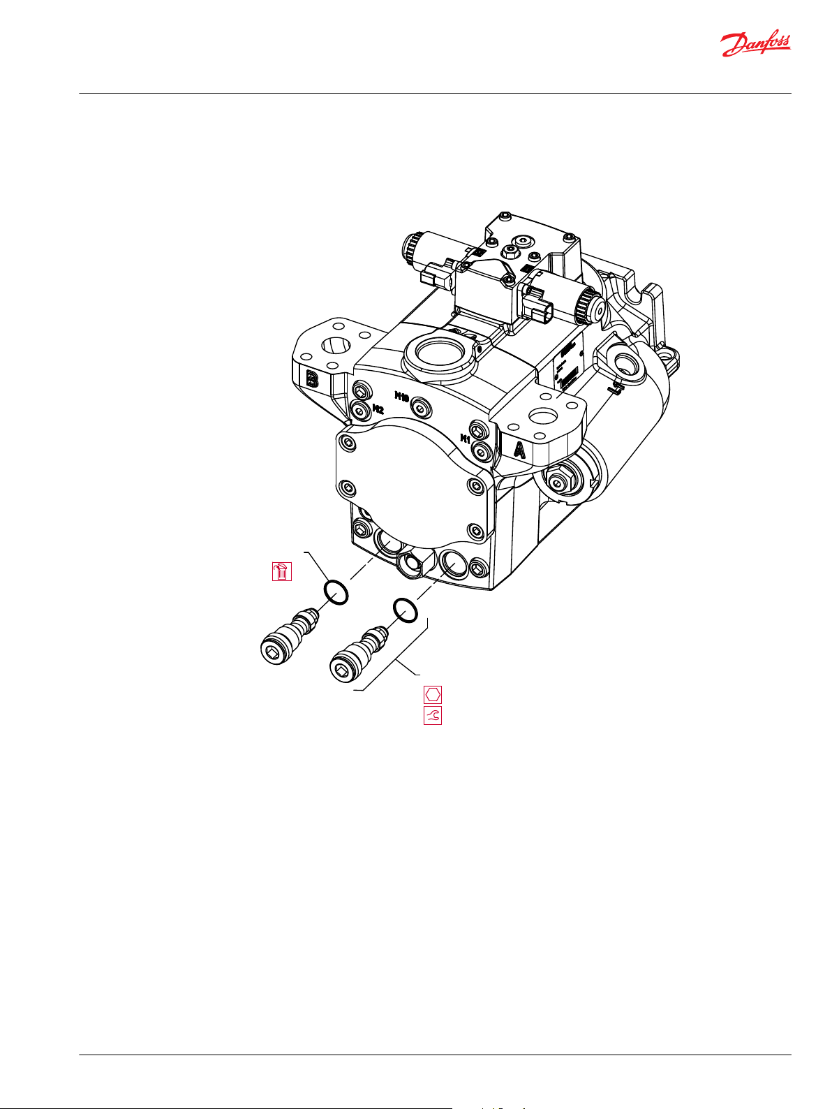
G090
G090A
12 mm
60 N•m [44 lbf•ft]
Service Manual
TMP Transit Mixer Axial Piston Pump, Size 070/089
Minor Repair
3. Operate the vehicle/machine through full range of controls to ensure proper operation. Check for
leaks.
HPRVs (P005431)
Charge Pressure Relief Valve
Replace the charge pressure relief valve (K001) as a complete unit. Do not attempt to repair the internal
components of the valve. Torque to 65 N•m [48 lbf•ft].
See Charge Pressure Relief Valve Adjustments on page 25 for adjustment instructions.
Removal
Using a 27 mm wrench, remove the charge pressure relief valve (K001). Discard seal O-ring (K050).
Inspection
Inspect the sealing surfaces of the pump for nicks or scratches.
Reassembly
1. Lubricate and install new seal O-ring (K050).
2. Install the charge pressure relief valve. Torque to 65 N•m [48 lbf•ft].
©
Danfoss | July 2017 L1010109 | AX00000131en-US0203 | 41
Page 42

K050
K001
27 mm
65 N•m [48 lbf•ft]
Service Manual
TMP Transit Mixer Axial Piston Pump, Size 070/089
Minor Repair
3. Operate vehicle/machine through full range of controls to ensure proper operation.
Charge Pressure Relief Valve (P005620)
42 | © Danfoss | July 2017 L1010109 | AX00000131en-US0203
Page 43

K010
Charge pressure
locking nut
H050
Charge pump
cover screw
G050/F050
O-ring plug
M12x1.5
G090
High pressure
relief valve
G090
High pressure
relief valve
G100
Rear cover
Service Manual
TMP Transit Mixer Axial Piston Pump, Size 070/089
Torque Chart
Fastener Size and Torques
Item Fastener Wrench size Torque
D015 Neutral adjust screw 4 mm internal hex NA
D050 Coil mounting bolt 4 mm internal hex 8 N•m [6 lbf•ft]
D060 Neutral adjust locking nut 13 mm 10 N•m [7.5 lbf•ft]
D200 Swash plate feedback pin (not shown) 13 mm deep well socket 25 N•m [18 lbf•ft]
D250 Electric control mounting bolt 5 mm internal hex 13.3 N•m [9.8 lbf•ft]
F080 Servo cylinder locking nut 58-62 hook wrench 80 N•m [59 lbf•ft]
M180, M185 Orifice 3 mm internal hex 2.5 N•m [1.84 lbf•ft]
G090 High pressure relief valve 12 mm internal hex 60 N•m [44 lbf•ft]
G100 Rear cover 10 mm internal hex 110 N•m [81 lbf•ft]
H050 Charge Pump Cover Screw 8 mm internal hex 30 N•m [22 lbf•ft]
H080 Auxiliary pad mounting bolt 8 mm internal hex 30 N•m [22 lbf•ft]
K001 Charge pressure adjusting screw 13 mm hex deep socket NA
Charge pressure locking nut 27 mm 65 N•m [48 lbf•ft]
W055 Speed sensor mounting bolt 5 mm internal hex 8 N•m [6 lbf•ft]
Plug Size and Torques
Item O-ring plug Wrench size Torque
D065 7/16 - 20 3/16 internal hex 12 N•m [9 lbf•ft]
B030 M22x1.5 10 mm internal hex 40 N•m [29.5 lbf•ft]
G050, F090 M12x1.5 6 mm internal hex 21 N•m [15.5 lbf•ft]
EDC Fasteners and Plugs
P005433E
©
Danfoss | July 2017 L1010109 | AX00000131en-US0203 | 43
Page 44

F080
Servo can locking nut
D060
Neutral adjust locking nut
D015
Neutral adjusting screw
D065
O-ring plug 7/16 - 20
B030
O-ring plug M22x1.5
D250
Electric control mounting bolt
D050
Coil mounting bolt
Service Manual
TMP Transit Mixer Axial Piston Pump, Size 070/089
Torque Chart
P005432E
44 | © Danfoss | July 2017 L1010109 | AX00000131en-US0203
Page 45

K010
Charge pressure
locking nut
H050
Charge pump
cover screw
G050/F050
O-ring plug
M12x1.5
G090
High pressure
relief valve
G090
High pressure
relief valve
G100
Rear cover
Service Manual
TMP Transit Mixer Axial Piston Pump, Size 070/089
Torque Chart
MDC Fasteners and Plugs
P005617E
©
Danfoss | July 2017 L1010109 | AX00000131en-US0203 | 45
Page 46

F080
Servo can locking nut
D060
Neutral adjust locking nut
B030
O-ring plug M22x1.5
D250
Mechanical control mounting bolt
D698
Neutral adjustment screw
Service Manual
TMP Transit Mixer Axial Piston Pump, Size 070/089
Torque Chart
P005618E
46 | © Danfoss | July 2017 L1010109 | AX00000131en-US0203
Page 47

Service Manual
TMP Transit Mixer Axial Piston Pump, Size 070/089
©
Danfoss | July 2017 L1010109 | AX00000131en-US0203 | 47
Page 48

Danfoss
Power Solutions GmbH & Co. OHG
Krokamp 35
D-24539 Neumünster, Germany
Phone: +49 4321 871 0
Danfoss
Power Solutions ApS
Nordborgvej 81
DK-6430 Nordborg, Denmark
Phone: +45 7488 2222
Danfoss
Power Solutions (US) Company
2800 East 13th Street
Ames, IA 50010, USA
Phone: +1 515 239 6000
Danfoss
Power Solutions Trading
(Shanghai) Co., Ltd.
Building #22, No. 1000 Jin Hai Rd
Jin Qiao, Pudong New District
Shanghai, China 201206
Phone: +86 21 3418 5200
Products we offer:
Comatrol
www.comatrol.com
Turolla
www.turollaocg.com
Hydro-Gear
www.hydro-gear.com
Daikin-Sauer-Danfoss
www.daikin-sauer-danfoss.com
Bent Axis Motors
•
Closed Circuit Axial Piston
•
Pumps and Motors
Displays
•
Electrohydraulic Power
•
Steering
Electrohydraulics
•
Hydraulic Power Steering
•
Integrated Systems
•
Joysticks and Control
•
Handles
Microcontrollers and
•
Software
Open Circuit Axial Piston
•
Pumps
Orbital Motors
•
PLUS+1® GUIDE
•
Proportional Valves
•
Sensors
•
Steering
•
Transit Mixer Drives
•
Danfoss Power Solutions is a global manufacturer and supplier of high-quality hydraulic and
electronic components. We specialize in providing state-of-the-art technology and solutions
that excel in the harsh operating conditions of the mobile off-highway market. Building on
our extensive applications expertise, we work closely with our customers to ensure
exceptional performance for a broad range of off-highway vehicles.
We help OEMs around the world speed up system development, reduce costs and bring
vehicles to market faster.
Danfoss – Your Strongest Partner in Mobile Hydraulics.
Go to www.powersolutions.danfoss.com for further product information.
Wherever off-highway vehicles are at work, so is Danfoss. We offer expert worldwide support
for our customers, ensuring the best possible solutions for outstanding performance. And
with an extensive network of Global Service Partners, we also provide comprehensive global
service for all of our components.
Please contact the Danfoss Power Solution representative nearest you.
Local address:
Danfoss can accept no responsibility for possible errors in catalogues, brochures and other printed material. Danfoss reserves the right to alter its products without notice. This also applies to products
already on order provided that such alterations can be made without changes being necessary in specifications already agreed.
All trademarks in this material are property of the respective companies. Danfoss and the Danfoss logotype are trademarks of Danfoss A/S. All rights reserved.
©
Danfoss | July 2017 L1010109 | AX00000131en-US0203
 Loading...