

Page 1
Technical Information
Transit Mixer Axial Piston Motor
Size 070/084/089
powersolutions.danfoss.com
Page 2

Technical Information
TMM Transit Mixer Axial Piston Motor, Size 070/084/089
Revision history Table of revisions
Date Changed Rev
June 2017 Update to Engineering Tomorrow 0202
Mar 2014 Converted to Danfoss layout – DITA CMS BA
10 Aug 2012 New TMM images AD
15 Feb 2012 TMM detail view added AC
20 Jan 2012 Pictures` numbers were added, MMC change. AB
08 Dec 2011 First edition AA
2 | © Danfoss | June 2017 L1108123 | BC00000193en-US0202
Page 3

Technical Information
TMM Transit Mixer Axial Piston Motor, Size 070/084/089
Contents
Revisions
Technical Specifications
Literature reference ........................................................................................................................................................................5
General description......................................................................................................................................................................... 5
TMM fixed displacement motor sectional view.................................................................................................................... 6
System schematic.............................................................................................................................................................................6
TMM technical data......................................................................................................................................................................... 7
Output Speed...............................................................................................................................................................................9
System Pressure...........................................................................................................................................................................9
Case Pressure................................................................................................................................................................................9
External Shaft Seal Pressure.................................................................................................................................................... 9
Temperature................................................................................................................................................................................. 9
Viscosity........................................................................................................................................................................................10
Filtration............................................................................................................................................................................................ 10
Case Drain.........................................................................................................................................................................................10
Reservoir............................................................................................................................................................................................10
Determination of nominal motor sizes..................................................................................................................................11
High-pressure relief valve (HPRV).............................................................................................................................................11
Anti-cavitation valve.....................................................................................................................................................................12
Loop flushing shuttle spool........................................................................................................................................................12
Loop flushing relief valve............................................................................................................................................................12
Speed sensor description............................................................................................................................................................13
Speed and temperature sensor...........................................................................................................................................13
Sensor PPU, KPP*13808..........................................................................................................................................................14
Master Model Code
TMM master model code............................................................................................................................................................ 15
Operation
Bearing life........................................................................................................................................................................................17
Bearing life with no external shaft side load...................................................................................................................17
External radial shaft loads......................................................................................................................................................17
Mounting Flange Loads...............................................................................................................................................................18
Estimating overhung load moments.................................................................................................................................18
Output shafts...................................................................................................................................................................................19
Installation drawings
Dimensions.......................................................................................................................................................................................22
©
Danfoss | June 2017 L1108123 | BC00000193en-US0202 | 3
Page 4

Technical Information
TMM Transit Mixer Axial Piston Motor, Size 070/084/089
Revisions
4 | © Danfoss | June 2017 L1108123 | BC00000193en-US0202
Page 5
Technical Information
TMM Transit Mixer Axial Piston Motor, Size 070/084/089
Technical Specifications
Literature reference
Further available literature
Title
Speed and Temperature Sensor
Hydraulic Fluids and Lubricants
Design Guideline for Hydraulic Fluid Cleanliness
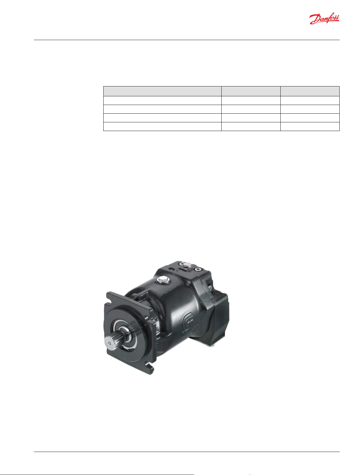
TMM Axial Piston Motor
General description
This motor is designed primarily to be combined with others pumps in closed circuit system to transfer
hydraulic power, especially for Transit Mixer Application.
Innovation with reliable technology
•
Loop flushing device integrated
•
High pressure relieve valves integrated
•
Anti-cavitation valves – optional
•
Speed and temperature sensor – optional
•
Speed sensor
•
Metric / Inch connections
•
High pressure ports for 3000 and 6000 psi on one side
•
Sizes: 70 cm3, 84 cm3 and 89 cm
•
3
Type
Technical Information
Technical Information
Technical Information
Service Manual
Literature number
11046759
520L0463
520L0467
L1211037
TMM fixed displacement motor
©
Danfoss | June 2017 L1108123 | BC00000193en-US0202 | 5
Page 6
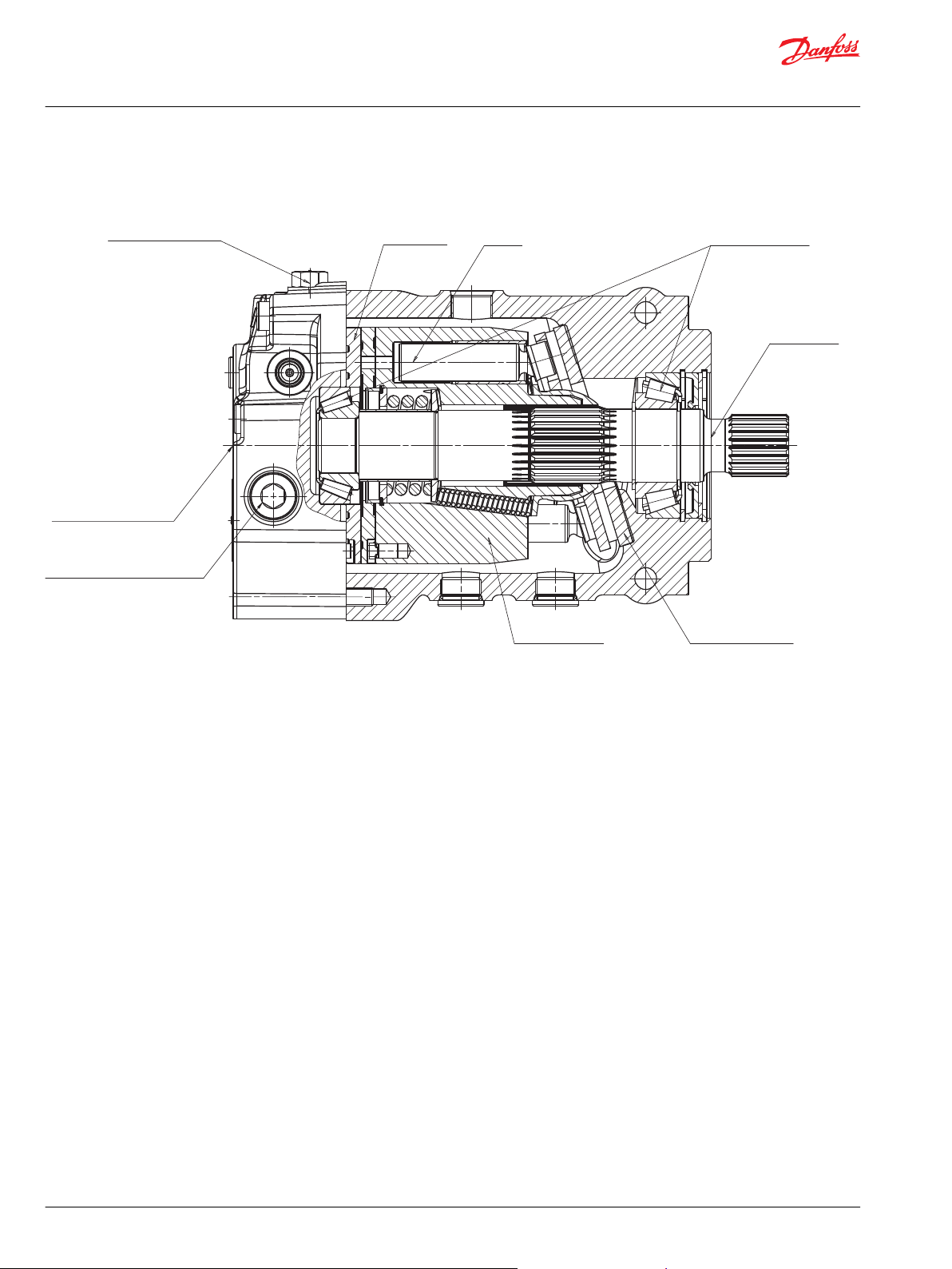
Anti-cavitation valve
High pressure relieve valve
Loop flushing valve
Valve plate
Piston
Conical bearings
Output shaft
Fixed swashplate
Cylinder block
Technical Information
TMM Transit Mixer Axial Piston Motor, Size 070/084/089
Technical Specifications
TMM fixed displacement motor sectional view
TMM cross-sectional view
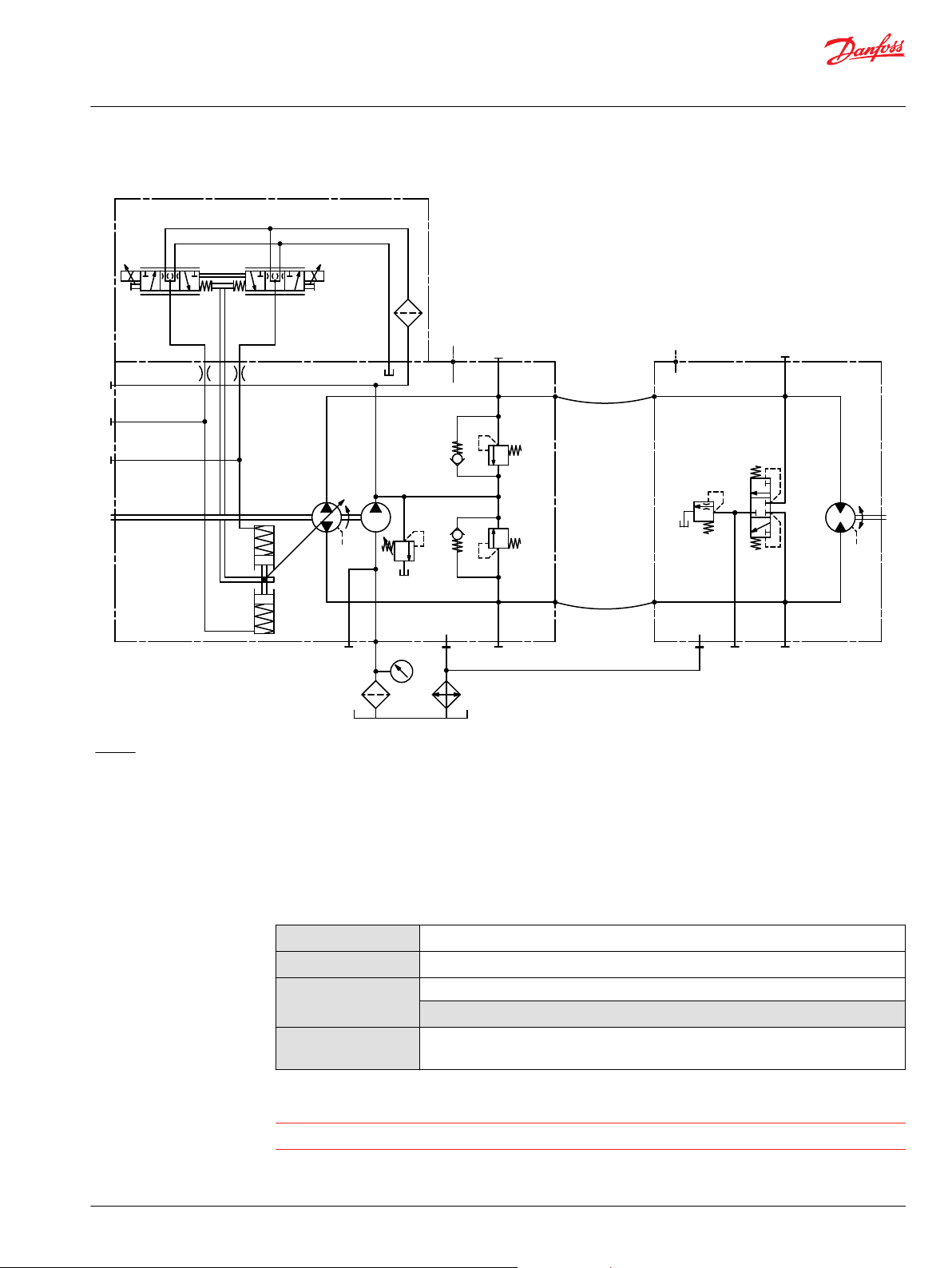
System schematic
The schematic below shows the function of a hydrostatic transmission using a TMP axial variable
displacement pump with electric proportional displacement control (EDC) and a TMM fixed displacement
motor with integrated loop flushing device.
6 | © Danfoss | June 2017 L1108123 | BC00000193en-US0202
Page 7
AA
B B
L2 M3
M3
M5
M4
TMMTMP
M2L2
S
M2
M10
L1
C2C1
M1 L1 M1
W
Technical Information
TMM Transit Mixer Axial Piston Motor, Size 070/084/089
Technical Specifications
TMM with TMP EDC
Legend:
A, B – System ports
L1, L2 – Case drain ports
M1, M2 – System A/B gage ports
M3 – Charge gage port, after filtering
M4, M5 – Servo gage ports
M10 – Charge pump inlet pressure port
S – Charge inlet port
Detailed information about ports see the section Installation drawings, pages Dimensions on page 22.
TMM technical data
General specifications
Design
Direction of rotation
Pipe connections
Recommended
installation position
Axial piston motor with fixed swashplate design with fixed displacement
Bi-directional
Main pressure ports: ISO split flange boss
Remaining ports: ISO/SAE straight thread O-ring boss
Motor installation position is discretionary
The housing must always be filled with hydraulic fluid. .
Warning
The front shaft seal must not be exposed to oil pressure from outside of the unit.
©
Danfoss | June 2017 L1108123 | BC00000193en-US0202 | 7
Page 8
Technical Information
TMM Transit Mixer Axial Piston Motor, Size 070/084/089
Technical Specifications
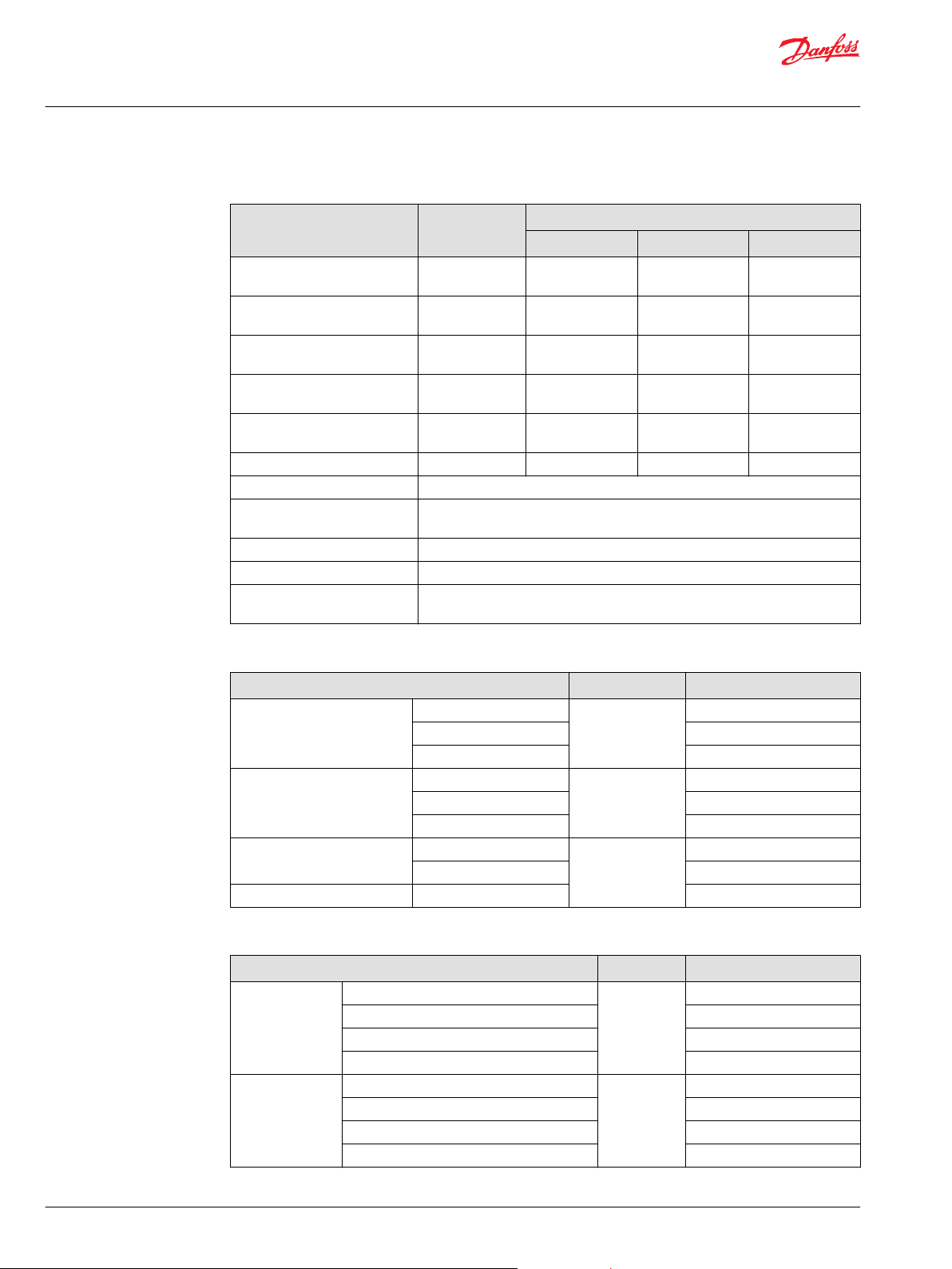
Technical data
Features Unit Size
Displacement maximum cm
Flow at rated (continuous) speed l/min
Torque (theoretical) N•m/bar
Mass moment of inertia of
rotating components
Weight dry (standard) kg
Oil volume l [US gal] 2 [0.53] 2 [0.53] 2 [0.53]
Mounting flange SAE ISO 3019/1 flange 127-4 (SAE C), M12x1,75
Output shaft Spline shaft SAE, 21 teeth, pitch = 16/32
Main port configuration Twin ports SAE J518b Size 1, with metric or inch screws
Case drain ports L1, L2 M22x1,5 (O-ring boss) or 7/8–14 UNF-2B
Other ports ISO straight thread O-ring boss or SAE. See Installation drawings, page
3
[in3]
[US gal/min]
[lbf•in/1000 psi]
2
kg•m
[lbf•ft2]
[lb]
Spline shaft SAE, 23 teeth, pitch = 16/32
Dimensions on page 22.
070 084 089
68.3
[4.17]
171
[45.2]
1.09
[665]
0.0209
[0.0159]
34.8
[76.9]
83.8
[5.11]
209.5
[55.3]
1.33
[812]
0.0209
[0.0159]
34.8
[76.9]
89.0
[5.43]
222.5
[58.8]
1.42
[867]
0.0209
[0.0159]
34.8
[76.9]
Operating parameters
Features Unit 070/084/089
Output speed Minimum min-1 (rpm) 100
Rated 2500
Maximum 2900
System pressure Max. working pressure bar
Maximum pressure 450 [6525]
[psi]
420 [6090]
Minimum pressure 10 [145]
Case pressure Rated bar
Maximum 5.0 [73]
[psi]
3.0 [44]
Lip seal external pressure Maximum 0.4 [5.8]
Fluid specifications
Features Unit 070/084/089
Viscosity Intermittent
Minimum 7 [49]
Recommended range 12-80 [66-370]
Maximum 1600 [7500]
Temperature
2
range
Minimum (cold start)
Recommended range 60-85 [140-185]
Rated 104 [220]
Maximum intermittent
1
3
1
mm2/s [SUS] 5 [42]
°C [°F] -40 [-40]
115 [240]
8 | © Danfoss | June 2017 L1108123 | BC00000193en-US0202
Page 9
Technical Information
TMM Transit Mixer Axial Piston Motor, Size 070/084/089
Technical Specifications
Fluid specifications (continued)
Features Unit 070/084/089
Filtration
(recommended
minimum)
1
Intermittent = Short term t < 1 min per incident and not exceeding 2 % of duty cycle based load-life
2
At the hottest point, normally case drain port
3
Cold start = Short term t < 3 min, p ≤ 50 bar [725 psi], n ≤ 1000 min-1(rpm)
Output Speed
Minimum speed is the lowest output speed. Operating below minimum speed limits the system can be
unstable.
Rated speed is the highest input speed recommended at full power condition. Operating at or below
this speed should yield satisfactory product life.
Maximum speed is the highest operating speed permitted. Exceeding maximum speed reduces product
life and can cause loss of hydrostatic power and braking capacity. Never exceed the maximum speed
limit under any operating conditions.
Cleanliness per ISO 4406 22/18/13
Efficiency (charge pressure filtration) β-ratio β15-20 = 75 (β10 ≥ 10)
Efficiency (suction and return line filtration) β35-45 = 75 (β10 ≥ 2)
Recommended inlet screen mesh size µm 100 – 125
System Pressure
Maximum working pressure is the highest recommended application pressure; and it is not intended to
be a continuous pressure. Propel systems with application pressures at, or below, this pressure should
yield satisfactory unit life given proper component sizing.
Maximum pressure is the highest allowable application pressure under any circumstance. Application
pressures above maximum working pressure will only be considered with duty cycle analysis and factory
approval.
Minimum pressure must be maintained under all operating conditions to avoid cavitation.
Case Pressure
Under normal operating conditions, the rated case pressure must not be exceeded. During cold start,
case pressure must be kept below maximum intermittent case pressure.
External Shaft Seal Pressure
In certain applications, the input shaft seal may be exposed to external pressures.
The shaft seal is designed to withstand an external pressure up to 0.4 bar [5.8 psi] above the case
pressure.
The case pressure limits must also be followed to ensure the shaft seal is not damaged.
Temperature
High temperature limits apply at the inlet port of the motor. The motor should run at or below the
maximum continuous temperature.
Cold oil generally does not affect the durability of motor components. It may affect the ability of oil to
flow and transmit power. For this reason, keep the temperature at 16°C
[60 °F] above the pour point of the hydraulic fluid.
Minimum (cold start) temperature relates to the physical properties of component materials.
Maximum continuous temperature is the allowed temperature at which normal life can be expected.
©
Danfoss | June 2017 L1108123 | BC00000193en-US0202 | 9
Page 10

Technical Information
TMM Transit Mixer Axial Piston Motor, Size 070/084/089
Technical Specifications
Peak (intermittent) temperature: the overheating temperature that is tolerable by the machine for a
transient/limited time.
Viscosity
Minimum viscosity occurs only during brief occasions of maximum ambient temperature and severe
duty cycle operation. It's the minimum acceptable viscosity to allow normal motor life.
Maximum viscosity occurs only during cold start at very low ambient temperatures. It's the upper limit
of viscosity that allows the motor to start.
Temperature and viscosity requirements must be concurrently satisfied. Use petroleum/mineral-based
fluids.
Filtration
To prevent premature wear, ensure only clean fluid enters the hydrostatic transmission circuit. A filter
capable of controlling the fluid cleanliness to ISO 4406 class 22/18/13
(SAE J1165) or better, under normal operating conditions, is recommended.
These cleanliness levels can not be applied for hydraulic fluid residing in the component housing/case or
any other cavity after transport.
Filtration strategies for TMP include only suction filtration. The selection of a filter depends on a number
of factors including the contaminant ingression rate, the generation of contaminants in the system, the
required fluid cleanliness, and the desired maintenance interval. Filters are selected to meet the above
requirements using rating parameters of efficiency and capacity.
Filter efficiency can be measured with a Beta ratio¹ (βX). For simple suction-filtered closed circuit
transmissions and open circuit transmissions with return line filtration, a filter with a β-ratio within the
range of β35-45 = 75 (β10 ≥ 2) or better has been found to be satisfactory. For some open circuit systems,
and closed circuits with cylinders being supplied from the same reservoir, a considerably higher filter
efficiency is recommended.
This also applies to systems with gears or clutches using a common reservoir.
For these systems, a charge pressure or return filtration system with a filter β-ratio in the range of β15-20
= 75 (β10 ≥ 10) or better is typically required.
Because each system is unique, only a thorough testing and evaluation program can fully validate the
filtration system. Please see Design Guidelines for Hydraulic Fluid Cleanliness Technical Information,
520L0467 for more information.
1
Filter βX-ratio is a measure of filter efficiency defined by ISO 4572. It is defined as the ratio of the
number of particles greater than a given diameter (“x” in microns) upstream of the filter to the number of
these particles downstream of the filter.
Case Drain
All TM pumps and motors are equipped with two case drain ports. Port selection and case drain routing
must enable the pump housing to maintain a volume of oil not less than half full and normal operating
case pressure limits of the unit are maintained. Case drain routing and design must consider unit case
pressure ratings.
A case drain line must be connected to one of the case outlets to return internal leakage to the system
reservoir.
Reservoir
The reservoir provides clean fluid, dissipates heat, removes entrained air, and allows for fluid volume
changes associated with fluid expansion during system operation. A correctly sized reservoir also
accommodates maximum volume changes during all system operating modes. It promotes de-aeration
10 | © Danfoss | June 2017 L1108123 | BC00000193en-US0202
Page 11

Technical Information
TMM Transit Mixer Axial Piston Motor, Size 070/084/089
Technical Specifications
of the fluid as it passes through, and accommodates a fluid dwell-time between 60 and 180 seconds,
allowing entrained air to escape.
Minimum reservoir capacity depends on the volume required to cool and hold the oil, allowing for
expansion due to temperature changes. A fluid volume of one to three times the motor output flow (per
minute) is satisfactory. The minimum recommended reservoir capacity is 125% of the fluid volume.
Put the return-line below the lowest expected fluid level to allow discharge into the reservoir for
maximum dwell and efficient de-aeration. A baffle (or baffles) between the return and suction lines
promotes de-aeration and reduces fluid surges.
Determination of nominal motor sizes
Use these formulae to determine the nominal motor size for a specific application:
Based on SI units Based on US units
Input flow: Q
l/min [US gal/min]
Output torque: M
N•m [lbf•in]
Output power: P
kW [hp]
Speed: n
-1
min
e
e
e
Variables: SI units [US units]
V
p
p
∆p
n
η
η
η
g
high
low
v
mh
t
=
Motor displacement per rev.
=
High pressure
=
Low pressure
=
p
– p
high
=
=
=
=
low
Speed
Motor volumetric efficiency
Mechanical (torque) efficiency
Overall efficiency (ηv • ηmh)
cm3/rev [in3/rev]
bar [psi]
bar [psi]
bar [psi]
min-1 (rpm)
High-pressure relief valve (HPRV)
The TM motors are optionally equipped with a combination of high-pressure relief and check valve. The
high-pressure relief function is a dissipative pressure control valve for the purpose of limiting excessive
system pressures. Each side of the transmission loop has a dedicated HPRV valve that is non-adjustable
with a factory set pressure.
When system pressure exceeds the factory setting of the valve, oil is passed from the high pressure
system loop into the low pressure system loop via the check valve.
©
Danfoss | June 2017 L1108123 | BC00000193en-US0202 | 11
Page 12

B
A
L1
M1
L2 M3 M2
High-pressure relief valve
High-pressure relief valve
Anticavitation valve
Loop Flushing Shuttle Spool
Loop Flushing Relief Valve
Technical Information
TMM Transit Mixer Axial Piston Motor, Size 070/084/089
Technical Specifications
TMM with High-pressure relief Valves and Anticavitation Valve
Anti-cavitation valve
The TM motors are optional equipment with anti-cavitation valve (ACV). ACV has to garantee a minimum
oil pressure in the low pressure side in case of low engine speed and high oil temperature.
Loop flushing shuttle spool
Loop flushing relief valve
An integral loop flushing shuttle spool is used to separate system A and system B pressures, see the
schematic below.
System delta pressure will cause the shuttle spool to shift, allowing the low side system pressure to flow
to the loop flushing relief valve.
Loop flushing shuttle valve section
Schematic
The loop flushing relief valve is incorporated into all TMM motors. Use the loop flushing option in
Installations that require fluid to be removed from the low pressure side of the system circuit due to
cooling requirements and also used to facilitate the removal of contaminants from the loop.
12 | © Danfoss | June 2017 L1108123 | BC00000193en-US0202
Page 13

0
4
8
12
16
20
24
28
0 2 4 6 8 10
432
1
12 14 16 18
Low system pressure minus case pre ssure (bar)
Case flow (l/min)
Case flow (US gal/min)
A3, 5 bar
A3, 13 bar
D2, 13 bar
4
3 2 1
P005418
5 6
Speed and temperature sensor
Connector
89.1 [3.508]
121.7 [4.79]
Technical Information
TMM Transit Mixer Axial Piston Motor, Size 070/084/089
Technical Specifications
The loop flushing valve is equipped with an orificed charge pressure relief valve designed with a cracking
pressure of 5.5, 13 and 16 bar. Valves are available with several orifice sizes to meet the flushing flow
requirements of all system operating conditions.
Loop flushing flow curves
Speed sensor description
Speed and temperature sensor
Function of the speed sensor is to detect the shaft speed and the direction of rotation.Typically the
sensor will be mounted to the housing of a Danfoss pump or motor and senses the speed from a target
ring that is rotating inside the pump or pistons in cylinder block in motor. Because of the digital output
signals for speed and direction and a non speed dependent output voltage level, the sensor is ideal for
high and low speed measurements.
For diagnostics and other purposes, the sensor also has the capability to detect the case oil temperature.
The speed sensor is designed for rugged outdoor, mobile or heavy industrial speed sensing applications.
The detection of the speed is contactless. It is custom-designed for Danfoss. It is a “plug and perform”
device that does not need any calibration or adjustments.
Connector, type DEUTSCH DTM-Series 6-Pin (DTM06-6S) pins need to be gold plated;
9 pistons (impulses per revolution);
Order number: 149055.
Connector, type DEUTSCH DTM-Series 6-Pin
Speed and temperature sensor
(DTM06-6S)
©
Danfoss | June 2017 L1108123 | BC00000193en-US0202 | 13
Sensor pinout:
1 – Speed signal 2
2 – Direction signal
3 – Speed signal 1
4 – Supply
5 – Ground
Page 14

Packard Metri-Pack 150 Series
4-way Connector (male)
Green
Black
White
Red
Direction
Ground
Speed signal
Power +
Connector: 12162144
Terminals: 12048074
Seals: 12048086
Connector
Target ring
200mm long
speed sensor wire
Sensor PPU, KPP* 13808
(85) [3.346]
129.2 [5.087]
Technical Information
TMM Transit Mixer Axial Piston Motor, Size 070/084/089
Technical Specifications
6 – Temperature
Sensor PPU, KPP*13808
Function of the speed sensor is to detect the shaft speed and the direction of rotation.
Number of teeth on target ring: 65 (impulses per revolution)
Connector terminal
Sensor PPU, KPP*13808
14 | © Danfoss | June 2017 L1108123 | BC00000193en-US0202
Page 15

Technical Information
TMM Transit Mixer Axial Piston Motor, Size 070/084/089
Master Model Code
TMM master model code
A – Product
TMM
B – Frame size / Displacement
070
084
089
C – Sense of rotation
B
Transit Mixer Motor
68.3 cm3/rev [4.17 in3/rev]
83.8 cm3/rev [5.11 in3/rev]
89.0 cm3/rev [5.43 in3/rev]
Bi-directional
G – End cap ports; High pressure setting
6MNN
3C35
6C42
Ports DN 25, Type 1, 420 bar [6000 psi], ISO 6162-2
Metric connections, without High-pressure relief valve
Ports DN 25, Type 2, 350 bar [3000 psi], ISO 6162-1
Inch connections, with High-pressure relief valve
Ports DN 25, Type 2, 420 bar [6000 psi], ISO 6162-2
Inch connections, with High-pressure relief valve
W – Special hardware features
NNN
NNC
2BN
9PN
9HN
Sensor- none, without Anticavitation valve
Sensor-none, with Anticavitation valve
Sensor PPU: KPP*13808 DIR SIGNAL “HIGH”/RIGHT, 65 impulsions/rev., without Anticavitation valve
Sensor none, Speed and temperature sensor of H1 ready (plugged), without Anticavitation valve
Speed and temperature sensor of H1, 9 impulsions/rev., without Anticavitation valve
L – Shaft
C
D
Splined shaft, 23 teeth, pitch = 16/32
Splined shaft, 21 teeth, pitch = 16/32
K – Loop flushing valve settings
A3F
A3M
D2M
Valve cone with 3x orifice ø1,5 mm and flow of 14,5 l/min by 25 bar,
Opening pressure 5,5 bar, (in conjunction with SPV, ACV)
Valve cone with 3x orifice ø1,5 mm and flow of 14,5 l/min by 25 bar,
Opening pressure 13 bar (in conjunction with SPV)
Valve cone with 2x orifice ø1,3 mm and flow of 10 l/min by 25 bar,
Opening pressure 13 bar(in conjunction with TMP)
©
Danfoss | June 2017 L1108123 | BC00000193en-US0202 | 15
Page 16

Technical Information
TMM Transit Mixer Axial Piston Motor, Size 070/084/089
Master Model Code
F – Special features
NSN
NDN
BSN
BDN
GSN
GDN
No paint, Name plate "Slovakia"
No paint, Name plate "Danfoss"
Black paint, Name plate "Slovakia"
Black paint, Name plate "Danfoss"
Gray paint, Name plate "Slovakia"
Gray paint, Name plate "Danfoss"
16 | © Danfoss | June 2017 L1108123 | BC00000193en-US0202
Page 17

Size 070 L20 = 33 727 •
( ) • ( )
240
p
1800
n
⁄
Size 084 L20 = 17 090 •
( ) • ( )
240
p
1800
n
⁄
Size 089 L20 = 13 952 •
( ) • ( )
240
p
1800
n
⁄
Technical Information
TMM Transit Mixer Axial Piston Motor, Size 070/084/089
Operation
Bearing life
Bearing life with no external shaft side load
Normal bearing life with no external shaft side load in L20 hours is shown in the table below. The figures
reflect a continuous delta pressure, shaft speed, maximum displacement, and no external shaft side load.
The data is based on a standard charge pressure of 20 bar [290 psi].
Bearing life with no external shaft side load
Unit Size 070 Size 084 Size 089
Shaft speed
Delta pressure – ∆p
Bearing life – L
Conversion of bearing life for other pressure (p) and speed (n):
20
min-1 (rpm) 1800 1800 1800
bar [psi] 240 [3480] 240 [3480] 240 [3480]
hours 33 727 17 090 13 952
©
Danfoss | June 2017 L1108123 | BC00000193en-US0202 | 17
External radial shaft loads
TM motors are designed with bearings that can accept some external radial and axial loads.
The external radial shaft load limits are a function of the load position and orientation, and the operating
conditions of the unit. The maximum allowable radial load (Re) is based on the maximum external
moment (Me) and the distance (L) from the mounting flange to the load. In applications with external
radial shaft loads, minimize the impact by positioning the load at 0° or 180° as shown in the figure below.
The external radial and axial shaft load are limited by the bearing life L20 =10 000 [h], delta system
pressure 240 bar, speed 1800 min-1 and external radial load at 270°.
It may be determined using the following table and formula below.
Maximum external shaft load for size 089
External radial moment – M
External axial force – F
External axial force – F
in
out
e
N•m [lbf•in] 0 32.6 [288]
N [lbf] -2440 [-548] -2020 [-454]
2790 [627] 2400 [539]
Page 18

L
F out (+)
270° Re
Re
Me
180° Re
90° Re
0° Re
F in (-)
e
=
M
e
Based on SI units: Based on US units:
M = g • G • W • L M = G • W • L
Where:
M = Rated load moment N•m [lbf•in]
g = Gravity 9.81 m/s
2
G = Calculation factor for max. acceleration 30
W = Weight of pump kg [lb]
L = Distance from mounting f ange to pump center of gravity m [in]
Technical Information
TMM Transit Mixer Axial Piston Motor, Size 070/084/089
Operation
Radial load position
Where:
Me = shaft moment
L = flange distance
Re = external force to the shaft
Contact your Danfoss representative for an evaluation of unit bearing life.
Mounting Flange Loads
Estimating overhung load moments
TMM load moment M
18 | © Danfoss | June 2017 L1108123 | BC00000193en-US0202
Page 19

W
Technical Information
TMM Transit Mixer Axial Piston Motor, Size 070/084/089
Operation
Rated and maximum torque ratings
W L Max. load moment M
35 kg [77 lb] 0,1338 mm [5.268 in] 1378 N•m [12 170 lbf•in]
Output shafts
Rated and maximum torque ratings for each available shaft is shown in the following table:
Specifications
Spline Min active spline length Rated torque* Maximum torque**
mm [in] N•m [lbf•in] N•m [lbf•in]
21 teeth, 16/32 pitch 30.7 [1.21] 660 [5840] 1200 [10 620]
23 teeth, 16/32 pitch 30.7 [1.21] 790 [6990] 1600 [14 160]
1
The specified torque rating of the shaft documented above is based on the cross-sectional diameter of
the shaft, through the keyway, and assumes the proper clamp and fit between shaft and coupling.
Danfoss guarantees the design and manufactured quality of the splined shaft. The customer is
responsible for the design and manufactured quality of the mating female coupling and key and applied
torque on the nut.
Danfoss has made provisions for the key in accordance to the ISO specification with the understanding
that the key is solely to assist in the installation of the mating coupling.
Warning
Torque or loading inadvertently transmitted by the customer supplied key may lead to premature shaft
failure.
1
* Rated torque - measure of teeth wear. ** Maximum torque - ratings are based on torsional fatigue strength
©
Danfoss | June 2017 L1108123 | BC00000193en-US0202 | 19
Page 20

Technical Information
TMM Transit Mixer Axial Piston Motor, Size 070/084/089
Operation
ISO 3019-1 (SAE C, 23-teeth)
20 | © Danfoss | June 2017 L1108123 | BC00000193en-US0202
Page 21

Technical Information
TMM Transit Mixer Axial Piston Motor, Size 070/084/089
Operation
ISO 3019-1 (SAE C, 21-teeth)
©
Danfoss | June 2017 L1108123 | BC00000193en-US0202 | 21
Page 22

Gauge Port M2
System Pressure Port B
M12x1.5
Optional: 9/16-18 UNF-2B
Gauge Port M3
Flushing Pressure
M12x1.5
Optional: 9/16-18 UNF-2B
Loop Flushing Valve
Gauge Port M1
System Pressure Port A
M12x1.5
Optional: 9/16-18 UNF-2B
High Pressure
Relief Valve
Port ‘A’
High Pressure
Relief Valve
Port ‘B’
Charge Pressure Relief Valve
Anticavitation Valve
190.6
[7.504]
146 ±2.8
[5.748 ±0.11]
164 ±2
[6.457 ±0.079]
190 ±1.6
[7.47 ±0.063]
205
[8.071]
Ø15
[DIA 0.591 ]
0.8
-0.3
0.031
-0.012
57.25 (2x)
[2.254 ]
0.3
-0.5
0.012
-0.020
57.25 (2x)
[2.254 ]
0.3
-0.5
0.012
-0.020
Technical Information
TMM Transit Mixer Axial Piston Motor, Size 070/084/089
Installation drawings
Dimensions
TMM ports
22 | © Danfoss | June 2017 L1108123 | BC00000193en-US0202
Page 23

Case drain M22x1.5
Optional: 7/8-14UNF-2B
Optional: Port for sensor PPU
7/8-14UNF-2B
Optional: M22x1.5
Case drain port
M22x1.5
Optional: 7/8-14UNF-2B
Primer Free
(Entire surface)
Primer Free
(Entire surface)
2x Split flange boss per
ISO 6162-1 FPS1x25 or FPS2x25
except as noted
(centerline distances)
2x Split flange boss per
ISO 6162-1 FPS1x25 or FPS2x25
except as noted
(centerline distances)
Plugged - ready for speed
and temperature sensor
Optional: Speed and
temperature sensor
73
[2.874]
100
[3.937]
95
[3.74]
95.6
[3.764]
73
[2.874]
125
[4.921]
119
[4.685]
250
[9.843]
252
[9.921]
Ø50
[DIA 1.97]
Ø24 (2x)
[DIA 0.945]
41.6 (2x)
[1.638]
219
[8.622]
13
[0.512 ]
1.2
-0.5
0.047
-0.020
85
[3.346]
85
[3.346]
L2
P005416E
Technical Information
TMM Transit Mixer Axial Piston Motor, Size 070/084/089
Installation drawings
TMM dimensions
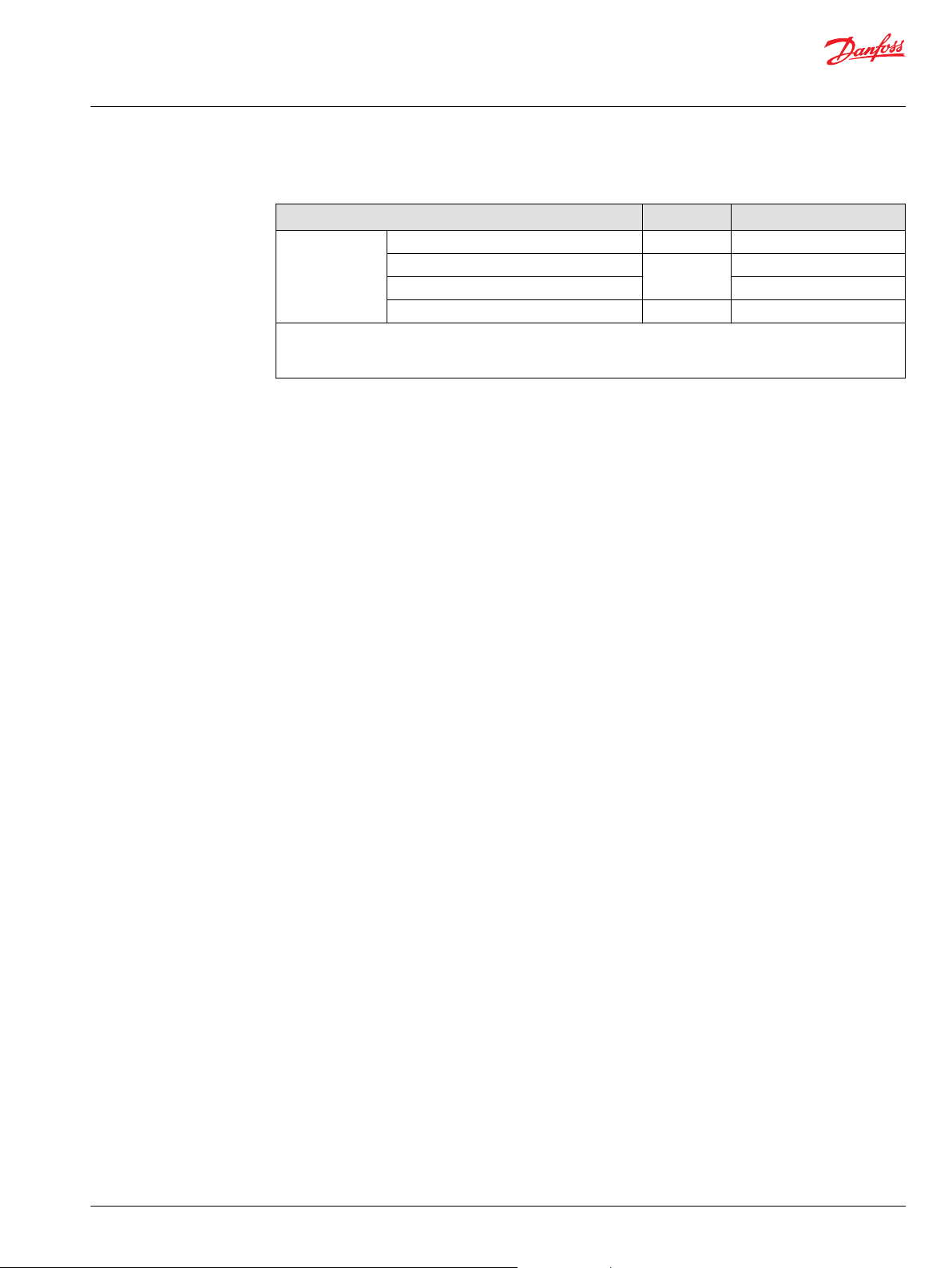
Ports description
Port Description TMM without HPRV TMM with HPRV
A, B
L1, L2
M1, M2
M3
System ports ISO DN25 SAE Ø 25.4 mm
Case drain ports M22x1.5 7/8-14
System A/B gauge ports M12x1.5 9/16-18
Flushing pressure port M12x1.5
Please contact Danfoss for specific installation drawings.
©
Danfoss | June 2017 L1108123 | BC00000193en-US0202 | 23
Page 24

Technical Information
TMM Transit Mixer Axial Piston Motor, Size 070/084/089
24 | © Danfoss | June 2017 L1108123 | BC00000193en-US0202
Page 25

Technical Information
TMM Transit Mixer Axial Piston Motor, Size 070/084/089
©
Danfoss | June 2017 L1108123 | BC00000193en-US0202 | 25
Page 26

Technical Information
TMM Transit Mixer Axial Piston Motor, Size 070/084/089
26 | © Danfoss | June 2017 L1108123 | BC00000193en-US0202
Page 27

Danfoss
Power Solutions GmbH & Co. OHG
Krokamp 35
D-24539 Neumünster, Germany
Phone: +49 4321 871 0
Danfoss
Power Solutions ApS
Nordborgvej 81
DK-6430 Nordborg, Denmark
Phone: +45 7488 2222
Danfoss
Power Solutions (US) Company
2800 East 13th Street
Ames, IA 50010, USA
Phone: +1 515 239 6000
Danfoss
Power Solutions Trading
(Shanghai) Co., Ltd.
Building #22, No. 1000 Jin Hai Rd
Jin Qiao, Pudong New District
Shanghai, China 201206
Phone: +86 21 3418 5200
Products we offer:
Comatrol
www.comatrol.com
Turolla
www.turollaocg.com
Hydro-Gear
www.hydro-gear.com
Daikin-Sauer-Danfoss
www.daikin-sauer-danfoss.com
Bent Axis Motors
•
Closed Circuit Axial Piston
•
Pumps and Motors
Displays
•
Electrohydraulic Power
•
Steering
Electrohydraulics
•
Hydraulic Power Steering
•
Integrated Systems
•
Joysticks and Control
•
Handles
Microcontrollers and
•
Software
Open Circuit Axial Piston
•
Pumps
Orbital Motors
•
PLUS+1® GUIDE
•
Proportional Valves
•
Sensors
•
Steering
•
Transit Mixer Drives
•
Danfoss Power Solutions is a global manufacturer and supplier of high-quality hydraulic and
electronic components. We specialize in providing state-of-the-art technology and solutions
that excel in the harsh operating conditions of the mobile off-highway market. Building on
our extensive applications expertise, we work closely with our customers to ensure
exceptional performance for a broad range of off-highway vehicles.
We help OEMs around the world speed up system development, reduce costs and bring
vehicles to market faster.
Danfoss – Your Strongest Partner in Mobile Hydraulics.
Go to www.powersolutions.danfoss.com for further product information.
Wherever off-highway vehicles are at work, so is Danfoss. We offer expert worldwide support
for our customers, ensuring the best possible solutions for outstanding performance. And
with an extensive network of Global Service Partners, we also provide comprehensive global
service for all of our components.
Please contact the Danfoss Power Solution representative nearest you.
Local address:
Danfoss can accept no responsibility for possible errors in catalogues, brochures and other printed material. Danfoss reserves the right to alter its products without notice. This also applies to products
already on order provided that such alterations can be made without changes being necessary in specifications already agreed.
All trademarks in this material are property of the respective companies. Danfoss and the Danfoss logotype are trademarks of Danfoss A/S. All rights reserved.
©
Danfoss | June 2017 L1108123 | BC00000193en-US0202
 Loading...