

Page 1
ORDER
RELAY
ID
DATA
SIGNAL
HARDOK
POWER
CANRUN
CANERR
OFF
ON
BLINKING
OUT
IN
RF signal detected
Incorrect ID signal from Ikusi system
CORRECT ELEMENTS
Abc
Abc
INCORRECT ELEMENTS -Check
troubleshooting guide
Installation Guide
Remote Control
TM70 and Ikontrol
Danfoss does not take responsibility for incorrect installation or
any frequency interference.
Chance of unintended machine movement on start up.
Ensure the machine is stopped for the entire duration of the
assembly process.
Keep the work area free and wear protective clothing.
Connect the power supply and the output connections using
the connection block diagram provided with the system. The
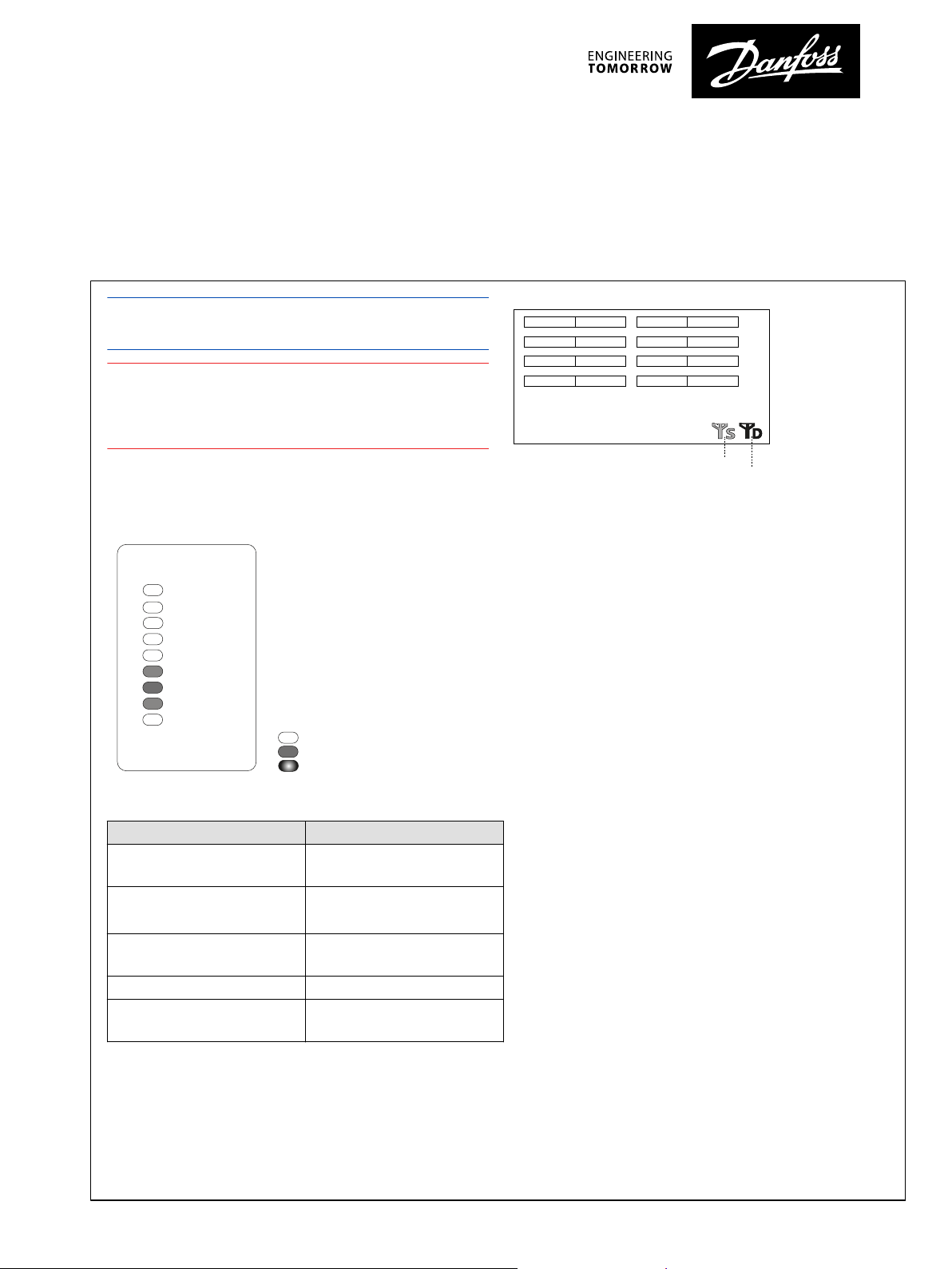
receiver will enter into scanning mode and show the following:
LED scanning mode (receiver)
Display scanning mode (receiver)
1. Place a charged battery in the transmitter
2. Turn the contact key
3. Push and pull out the STOP button
The LED of the transmitter will flash orange-green. If the
transmitter has a display, it displays the identification of the
machine, as well as the battery level
4. Press the start button
The green LED should now light indicating the transmitter
is transmitting
5. Turn off the transmitter using the STOP button
LED Description
DATA There is not another system active
in the area
SIGNAL
HARDOK GREEN; Absence of faults on the
POWER Power supply OK
CANRUN Communications with expansion
*
Only in receivers with CAN connection (except RCAN)
©
Danfoss | September 2021 AI293579926818en-000201 | 1
OFF; channels are signal free
BLINKING; RF signal detected on
the channels
boards
boards are OK
*
Page 2
ORDER
RELAY
ID
DATA
SIGNAL
HARDOK
POWER
CANRUN
CANERR
OFF
ON
BLINKING
OUT
IN
Correct ID (the icon shows the quiality of the link)
Linked state
No Ikusi RF signal detected(the icon shows the
quality)
Incorrect ID ( the icon shows the quality)
1
2
3
4
5
6
7
8
9
5
1
2
3
6
7
8
4
10
9
11
12
Installation Guide
TM70 and Ikontrol Installation Guide
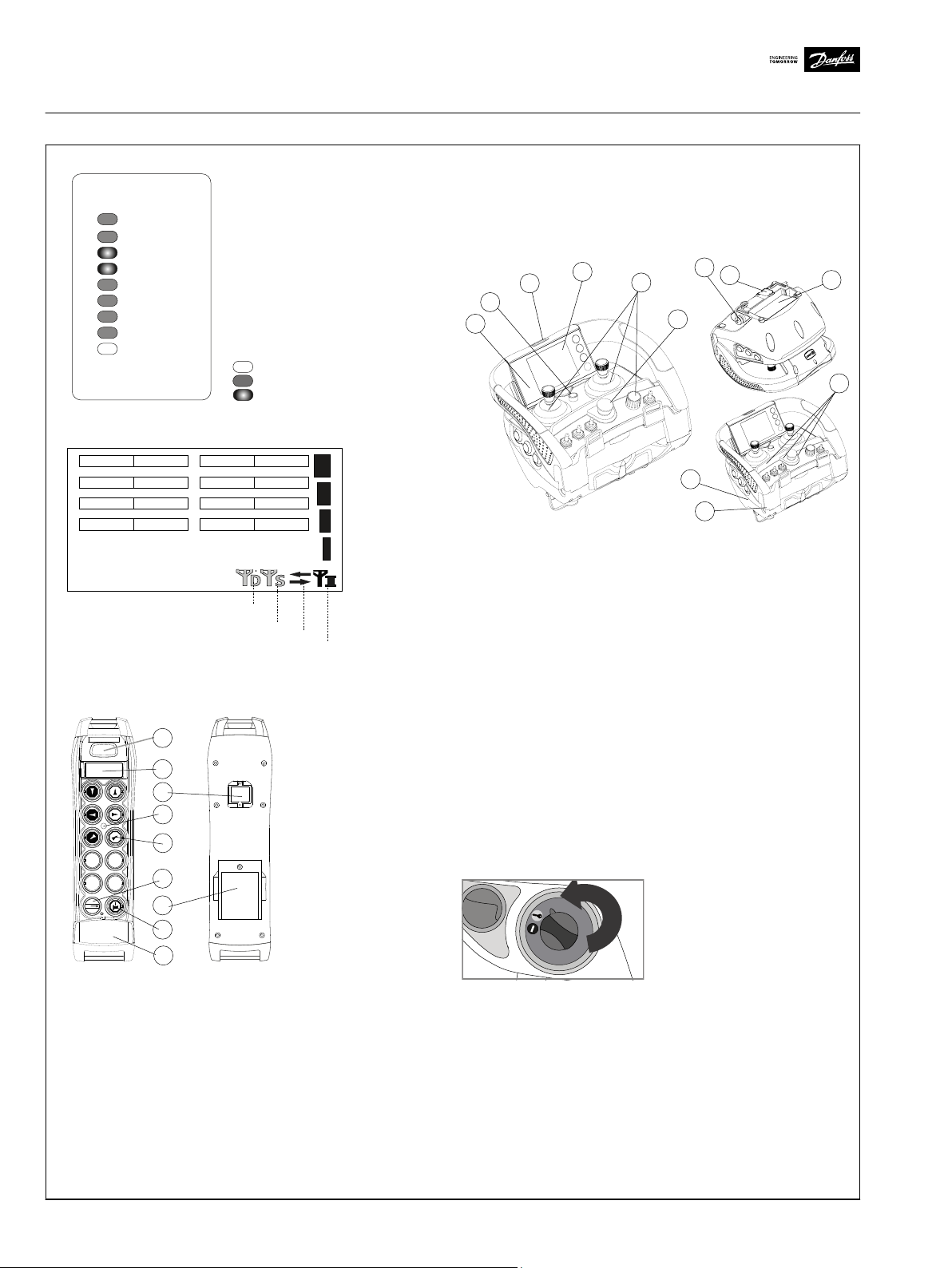
LEDs operational mode (receiver)
7. Optional: range limiter
8. Battery
9. Removable EEPROM
Ikontrol console box transmitter
1. Label for crane identification
2. LED
3. Maneuver element
4. Contact key or multi-key
Display operational mode (receiver)
5. Start button
6. STOP button
7. Optional: range limiter
8. 3.5" color TFT display (IK3); LCD monochrome 128x64
(IK2)
9. Removable EEPROM
10. Tether connection
11. Lateral push buttons
12. Battery
TM70 hand-held transmitter
1. Label for crane identification
2. LED
3. Maneuver button
4. Contact key
5. Start button
6. STOP button
2 | © Danfoss | September 2021 AI293579926818en-000201
Optional: display LCD
Contact key
Insert the multi-key and turn the position from 0 to 1. The
machine will not operate in 1 position as this is the natural
position of the multi-key.
Page 3

Installation Guide
TM70 and Ikontrol Installation Guide
Start/horn
In position 1, release the STOP push button and push start so
the transmitter starts emitting. The multi-key can also be used
to activate maneuvers such as the horn signal.
Toggle switch
The multi-key can also work as a toggle switch, configurable up
to 5 positions.
Receiver User Manuals & Datasheets
Transmitter User Manuals & Datasheets
https://www.danfoss.com/en/products/dps/electroniccontrols/human-machine-interfaces-hmi/plus1-remotecontrols/
©
Danfoss | September 2021 AI293579926818en-000201 | 3
Page 4

Danfoss can accept no responsibility for possible errors in catalogues, brochures and other printed material. Danfoss reserves the right to alter its products without notice. This also applies to products
already on order provided that such alterations can be made without subsequent changes being necessary in specifications already agreed.
All trademarks in this material are property of the respective companies. Danfoss and the Danfoss logotype are trademarks of Danfoss A/S. All rights reserved.
4 | © Danfoss | September 2021 AI293579926818en-000201
 Loading...