

Page 1
Technical Information
T1P Transit Mixer Axial Piston Pump
Size 069/089
powersolutions.danfoss.com
Page 2

Technical Information
T1P Transit Mixer Axial Piston Pump, Size 069/089
Revision history Table of revisions
Date Changed Rev
May 2016 Updated to Engineering Tomorrow design. 0201
August 2015 First edition 0101
2 | © Danfoss | May 2016 L1404561 | BC00000342en-US0201
Page 3

Technical Information
T1P Transit Mixer Axial Piston Pump, Size 069/089
Contents
Technical specifications
T1P general specifications.............................................................................................................................................................4
Technical data T1P 069/089..........................................................................................................................................................4
Operating parameters T1P 069/089.......................................................................................................................................... 5
Fluid specifications T1P .................................................................................................................................................................5
External radial shaft loads............................................................................................................................................................. 6
Bearing life T1P 069/089................................................................................................................................................................ 6
Mounting flange loads T1P 069/089......................................................................................................................................... 7
Charge pump.....................................................................................................................................................................................8
Charge pump flow and power curves, 17 cm³................................................................................................................. 8
Charge pump flow and power curves 24 cm³.................................................................................................................. 8
Model Code T1P 069/089
Control options
Electrical Displacement Control (EDC)................................................................................................................................... 11
EDC data for T1P....................................................................................................................................................................... 11
Control response.......................................................................................................................................................................12
EDC response time T1P...........................................................................................................................................................13
Manual Displacement Control (MDC) ....................................................................................................................................14
MDC principle............................................................................................................................................................................ 14
MDC general information......................................................................................................................................................15
Shaft rotation MDC.................................................................................................................................................................. 15
Control response.......................................................................................................................................................................15
MDC response time T1P.........................................................................................................................................................16
Neutral Start Switch (NSS)..................................................................................................................................................... 16
Case gauge port M14.............................................................................................................................................................. 17
Lever..............................................................................................................................................................................................17
Manual Over Ride (MOR) for T1.................................................................................................................................................18
Control-Cut-Off valve (CCO) for T1P........................................................................................................................................18
CCO solenoid data for T1P.....................................................................................................................................................19
Brake gauge port with MDC................................................................................................................................................. 19
Dimensions
T1P input shaft - option A5.........................................................................................................................................................20
T1P input shaft - option A6.........................................................................................................................................................21
T1P input shaft - option A7.........................................................................................................................................................22
T1P auxiliary mounting pad, option H1 (SAE A, 11 teeth) ..............................................................................................23
T1P auxiliary mounting pad, option H2 (SAE A, 9 teeth)................................................................................................. 24
T1P auxiliary mounting pad, option H3 (SAE B, 13 teeth) ..............................................................................................25
T1P auxiliary mounting pad, option H5 (SAE B-B, 15 teeth) ..........................................................................................26
Installation drawings
T1P 069/089 ports description..................................................................................................................................................27
Dimensions T1P 069 with EDC.................................................................................................................................................. 29
Dimensions T1P 069 with EDC.................................................................................................................................................. 30
Dimensions T1P 069 with EDC.................................................................................................................................................. 31
Dimensions T1P 089 with EDC.................................................................................................................................................. 32
Dimensions T1P 089 with EDC.................................................................................................................................................. 33
Dimensions T1P 089 with EDC.................................................................................................................................................. 34
Dimensions T1P with MDC......................................................................................................................................................... 35
Controls
T1P 069/089 Electric Displacement Control (EDC) with MOR, option A5 (24 V)..................................................... 38
T1P 069/089 Manual Displacement Control (MDC), option M1....................................................................................39
T1P 069/089 Manual Displacement Control (MDC) with NSS and CCO, option M6..............................................40
Filtration
T1P 069/089 suction filtration................................................................................................................................................... 41
©
Danfoss | May 2016 L1404561 | BC00000342en-US0201 | 3
Page 4

Technical Information
T1P Transit Mixer Axial Piston Pump, Size 069/089
Technical specifications
For definitions of the following specifications, see H1 Axial Piston Pumps, Basic Information 11062168,
chapter Operating parameters.
T1P general specifications
Design
Direction of rotation
Pipe connections
Recommended installation
position
Auxiliary cavity pressure
Technical data T1P 069/089
Axial piston pump of cradle swashplate design with variable displacement.
Clockwise / counterclockwise
Main pressure ports: ISO split flange boss
Remaining ports: SAE straight thread O-ring boss
Pump installation position is discretionary, however the recommended control position is on the top or at the side
with the top position preferred. If the pump is installed with the control at the bottom, flushing flow must be
provided through port M14 located on the EDC or MDC control.
Vertical input shaft installation is acceptable. If input shaft is at the top 1 bar case pressure must be maintained
during operation.
The housing must always be filled with hydraulic fluid. Recommended mounting for a multiple pump stack is to
arrange the highest power flow towards the input source.
Consult Danfoss Power Solutions for nonconformance to these guidelines.
Will be inlet pressure with internal charge pump, see Operating parameters T1P 069/089 on page 5.
Will be case pressure with external charge supply. Please verify mating pump shaft seal capability.
Feature Size 069 Size 089
Displacement
Flow at rated (continuous) speed
Torque at maximum displacement
(theoretical)
Mass moment of inertia of rotating
components
Mass [weight] dry without charge pump or
auxiliary mounting flange
Oil volume
Mounting flange
Input spline shaft
Auxiliary mounting flange
with metric fasteners,
Shaft outer diameter and splines
Suction port
Main port configuration
Case drain ports L2, L4
Other ports
Customer interface threads
3
69.2 cm
[4.22 in3]
243 l/min
[53.5 US gal/min]
1.1 N•m/bar
[672 lbf•in/1000 psi]
0.0077 kg•m
[0.0057 slug•ft2]
56 kg [123 lb] 62 kg [137 lb]
2 l [0.5 US gal] 2.6 l [0.67 US gal]
ISO 3019-1 flange 127-4 (SAE C)
21T, pitch = 16/32 per ANSI b92.1b Class 6e, with thread M10
23T, pitch = 16/32 per ANSI b92.1b Class 6e, with thread M10
23T, pitch = 16/32 with thread M10 and flange
ISO 3019-1, flange 82 - 2, outer Ø 16 mm - 4 (SAE A, 9 teeth)
ISO 3019-1, flange 82 - 2, outer Ø 19 mm - 4 (SAE A, 11 teeth)
ISO 3019-1, flange 101 - 2, outer Ø 22 mm - 4 (SAE B, 13 teeth)
ISO 3019-1, flange 101 - 2, outer Ø 25 mm - 4 (SAE B-B, 15 teeth)
Port ISO 11926-1 – 1 5∕8 -12 (SAE O-ring boss)
Ø25.4 - 450 bar split flange boss per ISO 6162, M12x1.75
Port ISO 11926-1 – 1 1∕16 -12 (SAE O-ring boss)
SAE O-ring boss
Metric fasteners
2
3
89.2 cm
[5.44 in3]
294 l/min
[77.7 US gal/min]
1.42 N•m/bar
[870 lbf•in/1000 psi]
0.0116 kg•m
[0.0086 slug•ft2]
2
4 | © Danfoss | May 2016 L1404561 | BC00000342en-US0201
Page 5
Technical Information
T1P Transit Mixer Axial Piston Pump, Size 069/089
Technical specifications
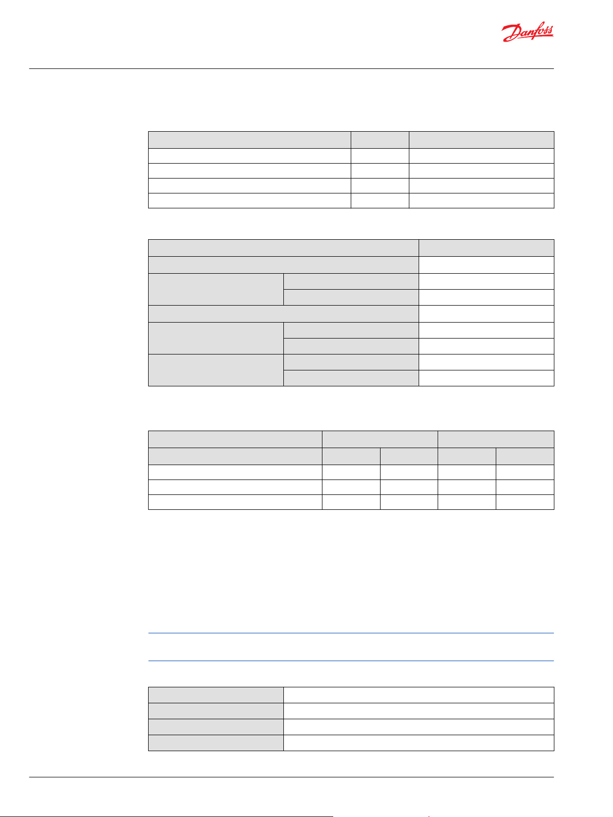
Operating parameters T1P 069/089
Feature Size 069 Size 089
Input speed
(at minimum
charge/control
pressure)
System pressure Maximum working pressure
Charge pressure Minimum
Control pressure Minimum (at corner power for EDC, MDC)
Charge pump
inlet pressure
Case pressure Rated
Lip seal external maximum pressure
1)
Performance (pressure and displacement) may be limited due to limited control pressure.
2)
Full performance (pressure and displacement) possible at minimum charge and control pressure supply.
Min. for internal1) and for external2) charge
supply.
Min. for full performance for internal charge
supply.
Rated
Maximum
Maximum pressure
Maximum low loop
Minimum low loop pressure
Maximum
Maximum
Rated
Minimum (cold start)
Maximum
Maximum
500 min-1 (rpm)
1200 min-1 (rpm)
3500 min-1 (rpm) 3300 min-1 (rpm)
4000 min-1 (rpm) 3800 min-1 (rpm)
420 bar [6092 psi]
450 bar [6527 psi]
45 bar [650 psi]
10 bar [145 psi]
16 bar [232 psi] 18 bar [261 psi]
35 bar [508 psi] 34 bar [493 psi]
14 bar [203 psi] 17 bar [247 psi]
40 bar [580 psi]
0.7 bar (absolute) [9 in Hg vacuum]
0.2 bar (absolute) [24 in Hg vacuum]
4 bar [58 psi]
3 bar [44 psi]
5 bar [73 psi]
0.4 [5.8 psi]
Fluid specifications T1P
Viscosity and temperature range
Feature Unit Data
Intermittent
1)
Minimum
Viscosity
mm2/s [SUS]
Recommended range
Maximum
Minimum3) (cold start)
Temperature
2)
range
1)
Intermittent = Short term t < 1min per incident and not exceeding 2 % of duty cycle based load-life
2)
At the hottest point, normally case drain port
3)
Cold start = Short term t < 3min, p ≤ 50 bar [725 psi], n ≤ 1000 min-1(rpm)
©
Danfoss | May 2016 L1404561 | BC00000342en-US0201 | 5
Recommended range
Rated
Maximum intermittent
°C [°F]
1)
5 [42]
7 [49]
12 – 80 [66 – 370]
1600 [7500]
-40 [-40]
60 – 85 [140 – 185]
104 [220]
115 [240]
Page 6
Re =
Me
L
P003 318E
L
270° Re
Re
Me
180° Re
90° Re
0° Re
Technical Information
T1P Transit Mixer Axial Piston Pump, Size 069/089
Technical specifications
Filtration, cleanliness level and βx-ratio (recommended minimum)
Cleanliness per ISO 4406
Efficiency βx (charge pressure filtration)
Efficiency βx (suction and return line filtration)
Recommended inlet screen mesh size
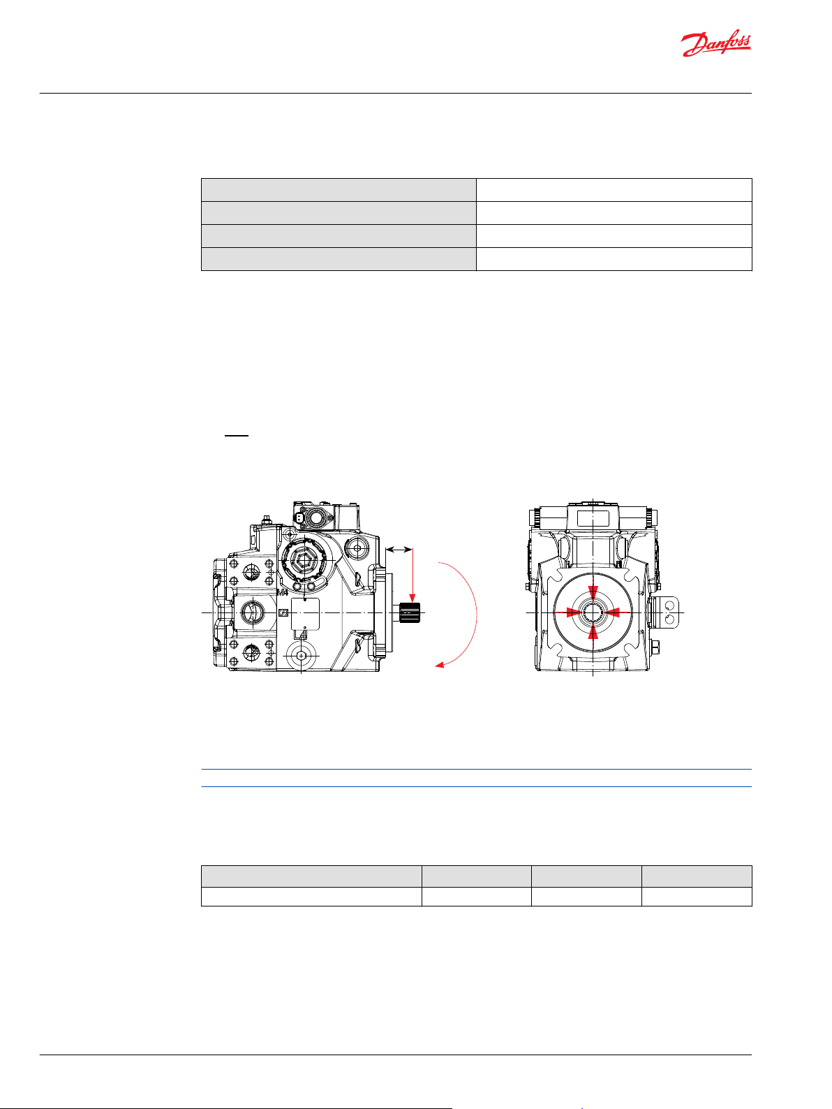
External radial shaft loads
The pumps are designed with bearings that can accept some external radial loads. The external radial
shaft load limits are a function of the load position and orientation, and the operating conditions of the
unit. External radial shaft loads impact lifetime. For lifetime calculations please contact Danfoss Power
Solutions representative.
The maximum allowable radial load (Re) is based on the maximum external moment (Me) and the
distance (L) from the mounting flange to the load. It may be determined using the following formula:
Radial load position
22/18/13
β
= 75 (β10 ≥ 10)
15-20
β
= 75 (β10 ≥ 2)
35-45
100 – 125 µm
Me = shaft moment
L = flange distance
Re = external force to the shaft
Thrust loads should be avoided. Contact factory in the event thrust loads are anticipated.
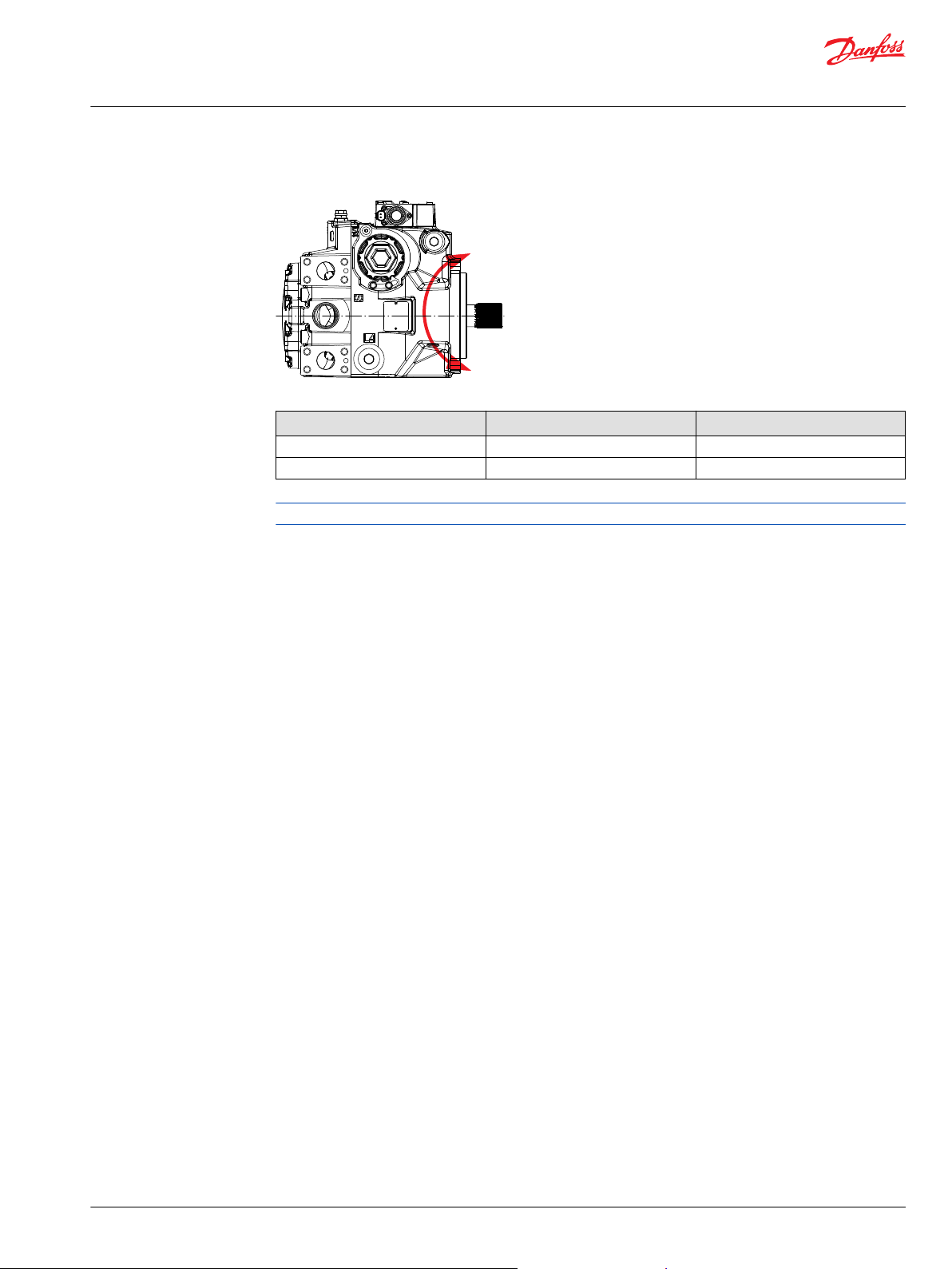
Bearing life T1P 069/089
Maximum external shaft load based on shaft deflection
External radial moment Unit Size 069 Size 089
M
e
N•m [lbf•in] 109 [965] 118 [1044]
All external shaft loads affect bearing life. In applications with external shaft loads, minimize the impact
by positioning the load at 0° or 180° as shown in the figure. Danfoss recommends clamp-type couplings
for applications with radial shaft loads.
Contact your Danfoss representative for an evaluation of unit bearing life if you have continuously
applied external loads exceeding 25 % of the maximum allowable radial load (Re) or the pump
swashplate is positioned on one side of center all or most of the time.
6 | © Danfoss | May 2016 L1404561 | BC00000342en-US0201
Page 7
P001 916
M
R
M
S
Technical Information
T1P Transit Mixer Axial Piston Pump, Size 069/089
Technical specifications
Mounting flange loads T1P 069/089
Mounting flange load Size 069 Size 089
Rated moment M
Shock load moment M
The moments shown above can be applied for top or side control orientation.
R
S
3700 N•m [32 750 lbf•in] 5630 N•m [49 830 lbf•in]
7900 N•m [69 920 lbf•in] 12 190 N•m [107 900 lbf•in]
©
Danfoss | May 2016 L1404561 | BC00000342en-US0201 | 7
Page 8
00
1.0
7.0
6.0
5.0
4.0
2.0
3.0
1
2
3
4
5
HP
kW
0 500 15001000 2000
Speed min-1(rpm)
3000 40002500 3500
P005 913
17 cm
3
[1.04 in
3
/rev]
0
1
3
6
9
12
15
10
20
30
40
50
60
US gal/min
l/min
0 500 15001000 2000
Speed min-1(rpm)
3000 40002500 3500
P005 912
17 cm
3
[1.04 in
3
/rev]
500 15001000 2000
Speed min-1(rpm)
3000 40002500 3500
9
8
7
6
5
4
3
2
1
0
12.0
11.0
10.0
9.0
8.0
7.0
6.0
5.0
4.0
3.0
2.0
1.0
HP
Kw
P005 911
24 cm
3
[1.46 in
3
/rev]
24
21
18
15
12
9
6
3
90
80
70
60
50
40
30
20
10
0
l/min
US gal/min
500 15001000 2000
Speed min-1(rpm)
3000 40002500 3500
24 cm
3
[1.46 in
3
/rev]
P005 910
Technical Information
T1P Transit Mixer Axial Piston Pump, Size 069/089
Technical specifications
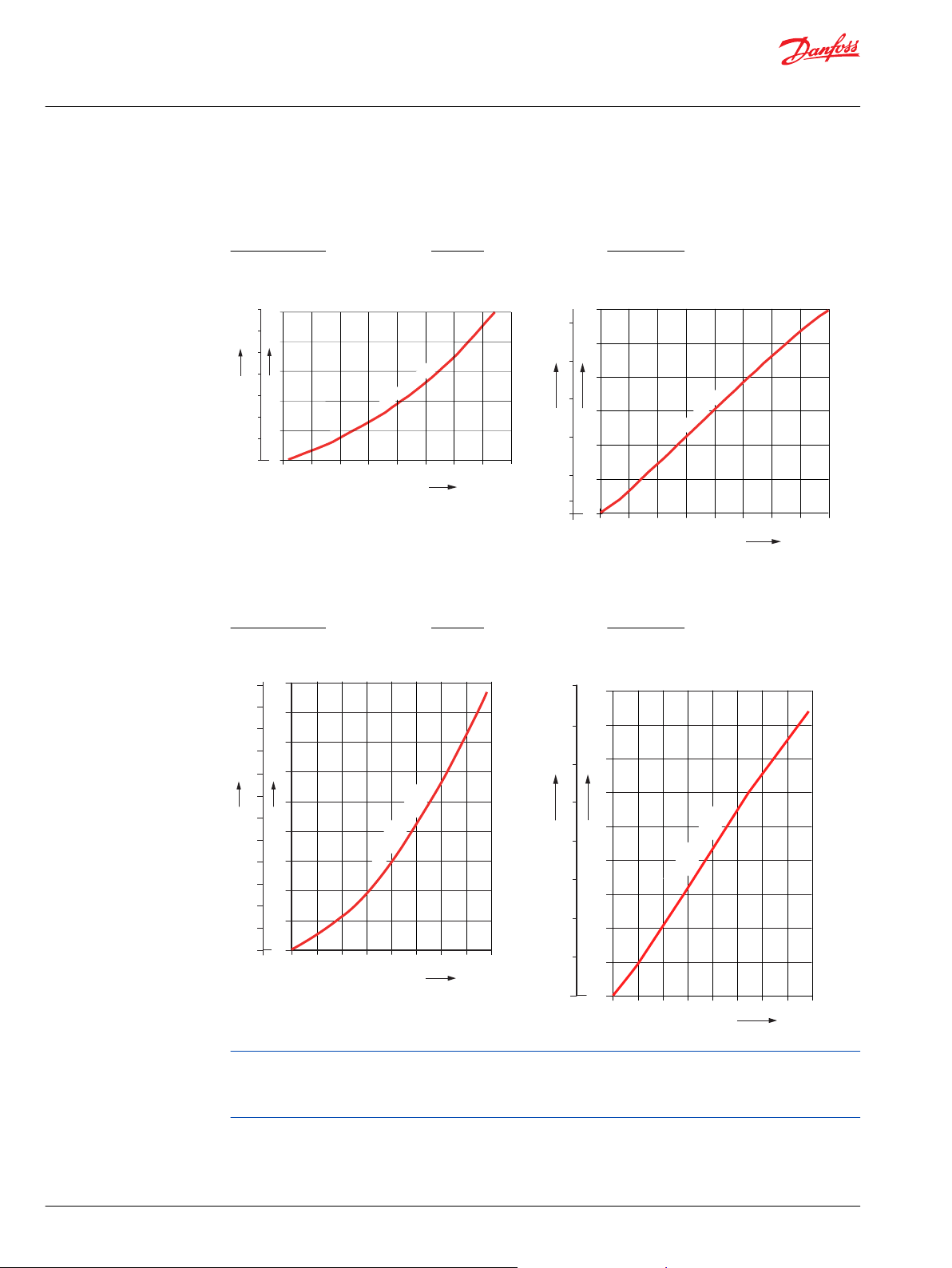
Charge pump
Charge pump flow and power curves, 17 cm³
Charge pressure: 20 bar [290 psi] / Viscosity: 11 mm²/s [63 SUS] / Temperature: 80°C [176°F]
Charge pump 17 cm³ power requirements
Charge pump 17 cm³ flow
Charge pump flow and power curves 24 cm³
Charge pressure: 20 bar [290 psi] / Viscosity: 11 mm²/s [63 SUS] / Temperature: 80°C [176°F]
Charge pump 24 cm³ power requirements
Charge pump 24 cm³ flow
8 | © Danfoss | May 2016 L1404561 | BC00000342en-US0201
For transit mixer application use the biggest charge pump which is available for particular size or contact
your Danfoss representative for application assistance if your application includes any of these
conditions.
Page 9
A A
C
3
D H
3
N K
4
2
K
4
2
L N
N
N
2 4
A B D EF G H J K M N S T V W X Y
T1 P
Technical Information
T1P Transit Mixer Axial Piston Pump, Size 069/089
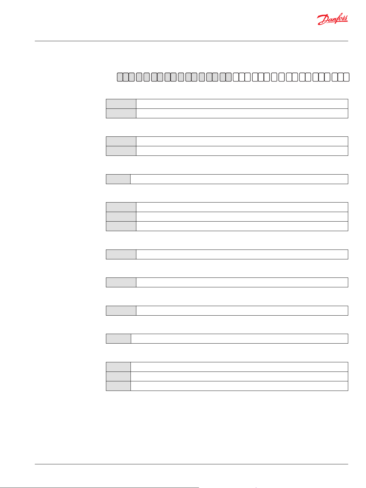
Model Code T1P 069/089
Displacement
069
089
A – Rotation
L
R
B – Product version
A
D – Control
A5
M1
M6
69.2 cm3 [4.22 in3]
89.2 cm3 [5.44 in3]
Left hand (counter clockwise)
Right hand (clockwise)
Revision code
Electric Displacement Control (EDC), 24V, Deutsch connector, with Manual override (MOR)
Manual Displacement Control (MDC)
Manual Displacement Control (MDC) with 24V, CCO and Neutral Start Switch, Deutsch Connector
F – Orifices (mm)
C3
No orifice
E – Displacement limiters
N
None
G – Endcap options (Twin port Code 62 Metric 4-Bolt flange)
D6
Endcap for suction filtration
H – Mounting flange
H
ISO 3019-1, 4-Bolt flange SAE C
J – Input shaft
A5
A6
A7
23T 16/32, with thread M10, with flange
21T 16/32 per ANSI b92.1b Class 6e, with thread M10
23T 16/32 per ANSI b92.1b Class 6e, with thread M10
©
Danfoss | May 2016 L1404561 | BC00000342en-US0201 | 9
Page 10
A A
C
3
D H
3
N K
4
2
K
4
2
L N
N
N
2 4
A B D EF G H J K M N S T V W X Y
T1 P
Technical Information
T1P Transit Mixer Axial Piston Pump, Size 069/089
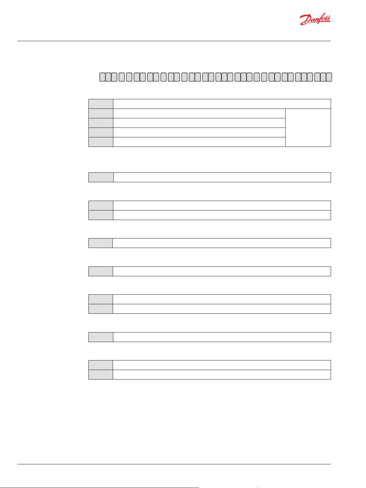
Model Code T1P 069/089
K – Auxiliary mounting pad
NN
H1
H2
H3
H5
M – Overpressure protection type, side “A”
N – Overpressure protection, side “B”
K42
S – Charge pump
C
M
None
ISO 3019-1, flange 82 - 2, outer Ø19 mm - 4 (SAE A, 11 teeth 16/32 coupling)
ISO 3019-1, flange 82 - 2, outer Ø16 mm - 4 (SAE A, 9 teeth 16/32 coupling)
ISO 3019-1, flange 101 - 2, outer Ø22 mm - 4 (SAE B, 13 teeth 16/32 coupling)
ISO 3019-1, flange 101 - 2, outer Ø25 mm - 4 (SAE B-B, 15 teeth 16/32 coupling)
420 bar [6090 psi] High pressure relief valve with bypass without pressure limiter
17 cm³/rev [1.03 in³/rev] (only for 69cc)
24 cm³/rev [1.46 in³/rev] (only for 89cc)
Shipping cover
T – Filtration
L
Suction filtration
V – Charge pressure relief setting
24
24 bar [348 psi]
W – Special hardware features
PN
H1
EDC/MDC (w/o handle) valve plate
EDC/MDC valve plate, MDC handle
X – Paint and nametag
NNN
Black paint and Danfoss nametag format A
Y – Special settings
NNN
M00
Default
MDC standard handle position
10 | © Danfoss | May 2016 L1404561 | BC00000342en-US0201
Page 11
P003 191
Feedback from
Swash plate
PTF00B
M14
C1 C2
F00A
P003 478E
P003 479E
"0"
-b -a
ba
100 %
100 %
Displacement
Current mA
1 2
P003 480
Technical Information
T1P Transit Mixer Axial Piston Pump, Size 069/089
Control options
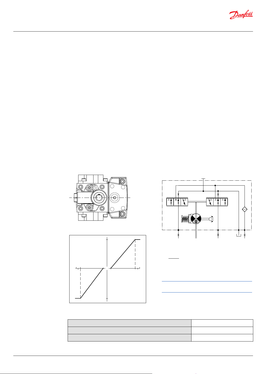
Electrical Displacement Control (EDC)
The Electrical Displacement Control (EDC) consists of a pair of proportional solenoids on each side of a
three-position, four-way porting spool. The proportional solenoid applies a force input to the spool,
which ports hydraulic pressure to either side of a double acting servo piston. Differential pressure across
the servo piston rotates the swashplate, changing the pump‘s displacement from full displacement in
one direction to full displacement in the opposite direction.
Under some circumstances, such as contamination, the control spool could stick and cause the pump to
stay at some displacement. A serviceable 125 μm screen is located in the supply line immediately before
the control porting spool.
Electrical Displacement Control
EDC schematic
Pump displacement vs. control current
©
Danfoss | May 2016 L1404561 | BC00000342en-US0201 | 11
EDC data for T1P
Control minimum current to stroke pump
Voltage a
24 V 330 mA 820 mA any order
*
Factory test current, for vehicle movement or application actuation expect higher or lower value.
*
b Pin connections
Connector
Page 12
Technical Information
T1P Transit Mixer Axial Piston Pump, Size 069/089
Control options
Connector ordering data
Description Quantity Ordering number
Mating connector 1 Deutsch® DT06-2S
Wedge lock 1 Deutsch® W2S
Socket contact (16 and 18 AWG) 2 Deutsch® 0462-201-16141
Danfoss mating connector kit 1 K29657
Solenoid data
Description 24 V
Maximum current
Nominal coil resistance
Inductance
PWM
IP Rating
*
PWM signal required for optimum control performance.
@ 20 °C [68 °F]
@ 80 °C [176 °F]
Range
Frequency (preferred)
IEC 60 529
DIN 40 050, part 9
920 mA
14.20 Ω
17.52 Ω
140 mH
70-200 Hz
*
100 Hz
IP 67
IP 69K with mating connector
Pump output flow direction vs. control signal
Shaft rotation CW CCW
Coil energized
Port A out in in out
Port B in out out in
Servo port pressurized M4 M5 M4 M5
*
For coil location see Installation drawings.
*
C1 C2 C1 C2
Control response
Controls are available with optional control passage orifices to assist in matching the rate of swashplate
response to the application requirements (e.g. in the event of electrical failure). The time required for the
pump output flow to change from zero to full flow (acceleration) or full flow to zero (deceleration) is a net
function of spool porting, orifices, and charge pressure. A swashplate response table is available for each
frame indicating available swashplate response times. Testing should be conducted to verify the proper
orifice selection for the desired response.
T1 pumps are limited in mechanical orificing combinations. Mechanical servo orifices are to be used only
for fail-safe return to neutral in the event of an electrical failure.
Typical response times shown below at the following conditions:
∆p
Viscosity and temperature
Charge pressure
Speed
250 bar [3626 psi]
30 mm²/s [141 SUS] and 50 °C [122 °F]
20 bar [290 psi]
1800 min-1 (rpm)
12 | © Danfoss | May 2016 L1404561 | BC00000342en-US0201
Page 13

Technical Information
T1P Transit Mixer Axial Piston Pump, Size 069/089
Control options
EDC response time T1P
Stroking direction (no orifice)
Neutral to full flow
Full flow to neutral
Frame size 069 Frame size 089
0.6 s 1.0 s
0.5 s 0.6 s
©
Danfoss | May 2016 L1404561 | BC00000342en-US0201 | 13
Page 14
P301 749
"0"
Lever rotation
"A"
Displacement
100 %
a
-a
100 %
"B"
-b
-d
b
c
d
-c
P301 752
P005 701
M14
M5
M4
M3
Technical Information
T1P Transit Mixer Axial Piston Pump, Size 069/089
Control options
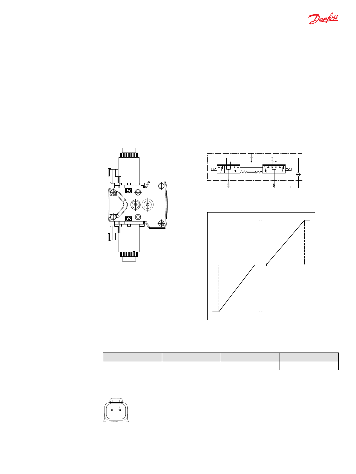
Manual Displacement Control (MDC)
MDC principle
An MDC is a Manual proportional Displacement Control (MDC). The MDC consists of a handle on top of a
rotary input shaft. The shaft provides an eccentric connection to a feedback link. This link is connected on
its one end with a porting spool. On its other end the link is connected the pumps swashplate.
This design provides a travel feedback without spring. When turning the shaft the spool moves thus
providing hydraulic pressure to either side of a double acting servo piston of the pump.
Differential pressure across the servo piston rotates the swash plate, changing the pump’s displacement.
Simultaneously the swashplate movement is fed back to the control spool providing proportionality
between shaft rotation on the control and swashplate rotation.
The MDC changes the pump displacement between no flow and full flow into opposite directions. Under
some circumstances, such as contamination, the control spool could stick and cause the pump to stay at
some displacement.
A serviceable 125 μm screen is located in the supply line immediately before the control porting spool.
The MDC is sealed by means of a static O-ring between the actuation system and the control block. Its
shaft is sealed by means of a special O-ring which is applied for low friction. The special O-ring is
protected from dust, water and aggressive liquids or gases by means of a special lip seal.
Manual Displacement Control
Pump displacement vs. control lever rotation
MDC schematic diagram
Where:
Deadband on B side – a = 3° ±1°
Maximum pump stroke – b = 30° +2/-1°
Required customer end stop – c = 36° ±3°
Internal end stop – d = 40°
Volumetric efficiencies of the system will have impacts on
the start and end input commands.
MDC torque
Torque required to move handle to maximum displacement
14 | © Danfoss | May 2016 L1404561 | BC00000342en-US0201
Torque required to hold handle at given displacement
Maximum allowable input torque
1.4 N•m [12.39 lbf•in ]
0.6 N•m [5.31 lbf•in]
20 N•m [177 lbf•in]
Page 15

C
CCW
CW
Technical Information
T1P Transit Mixer Axial Piston Pump, Size 069/089
Control options
MDC general information
In difference to other controls the MDC provides a mechanical deadband. This is required to overcome
the tolerances in the mechanical actuation.
The MDC contains an internal end stop to prevent over travel. The restoring moment is appropriate for
turning the MDC input shaft back to neutral only. Any linkages or cables may prevent the MDC from
returning to neutral.
The MDC is designed for a maximum case pressure of 5 bar and a rated case pressure of 3 bar. If the case
pressure exceeds 5 bar there is a risk of an insufficient restoring moment. In addition a high case pressure
can cause the NSS to indicate that the control is not in neutral. High case pressure may cause excessive
wear.
Customers can apply their own handle design but they must care about a robust clamping connection
between their handle and the control shaft and avoid overload of the shaft.
Customers can connect two MDC’s on a tandem unit in such a way that the actuation force will be
transferred from the pilot control to the second control but the kinematic of the linkages must ensure
that either control shaft is protected from torque overload.
To avoid an overload of the MDC, customers must install any support to limit the setting range of the
Bowden cable.
Caution
Using the internal spring force on the input shaft is not an appropriate way to return the customer
connection linkage to neutral.
Shaft rotation MDC
MDC shaft rotation data
Pump shaft rotation
MDC shaft rotation CW CCW CW CCW
Port A in (low) out (high) out (high) in (low)
Port B out (high) in (low) in (low) out (high)
Servo port high pressure M5 M4 M5 M4
*
As seen from shaft side.
*
Clock Wise (CW) Counter Clock Wise (CCW)
Control response
Controls are available with optional control passage orifices to assist in matching the rate of swashplate
response to the application requirements (e.g. in the event of electrical failure). The time required for the
pump output flow to change from zero to full flow (acceleration) or full flow to zero (deceleration) is a net
function of spool porting, orifices, and charge pressure. A swashplate response table is available for each
frame indicating available swashplate response times. Testing should be conducted to verify the proper
orifice selection for the desired response.
©
Danfoss | May 2016 L1404561 | BC00000342en-US0201 | 15
Page 16

P005 702
M14
M5
M4
M3
1 2
P003 480
Technical Information
T1P Transit Mixer Axial Piston Pump, Size 069/089
Control options
T1 pumps are limited in mechanical orificing combinations. Mechanical servo orifices are to be used only
for fail-safe return to neutral in the event of an electrical failure.
Typical response times shown below at the following conditions:
∆p
Viscosity and temperature
Charge pressure
Speed
MDC response time T1P
250 bar [3626 psi]
30 mm²/s [141 SUS] and 50 °C [122 °F]
20 bar [290 psi]
1800 min-1 (rpm)
Stroking direction (No orifice) Size 069
Neutral to full flow 0.4 s
Full flow to neutral 0.5 s
Size 089
0.5 s
0.6 s
Neutral Start Switch (NSS)
The Neutral Start Switch (NSS) contains an electrical switch that provides a signal of whether the control
is in neutral. The signal in neutral is Normally Closed (NC).
Neutral Start Switch schematic
Neutral Start Switch data
Max. continuous current with switching
Max. continuous current without switching
Max. voltage
Electrical protection class
8.4 A
20 A
36 V
DC
IP67 / IP69K with mating connector
Connector
Connector ordering data
Description Quantity Ordering number
Mating connector 1 Deutsch® DT06-2S
Wedge lock 1 Deutsch® W2S
16 | © Danfoss | May 2016 L1404561 | BC00000342en-US0201
Page 17

P301 749
P005 701
M14
M5
M4
M3
Technical Information
T1P Transit Mixer Axial Piston Pump, Size 069/089
Control options
Connector ordering data (continued)
Description Quantity Ordering number
Socket contact (16 and 18 AWG) 2 Deutsch® 0462-201-16141
Danfoss mating connector kit 1 K29657
Case gauge port M14
The drain port should be used when the control is mounted on the unit’s bottom side to flush residual
contamination out of the control.
MDC w/h drain port shown
Lever
MDC-controls are available with an integrated lever.
MDC schematic diagram
©
Danfoss | May 2016 L1404561 | BC00000342en-US0201 | 17
Page 18

P003 204
Feedback from
Swash plate
PTF00B
M14
C2
C1
F00A
P003 205E
W
Technical Information
T1P Transit Mixer Axial Piston Pump, Size 069/089
Control options
Manual Over Ride (MOR) for T1
All controls are available with a Manual Over Ride (MOR) either standard or as an option for temporary
actuation of the control to aid in diagnostics.
Unintended MOR operation will cause the pump to go into stroke. The vehicle or device must always be
in a „safe“ condition (i.e. vehicle lifted off the ground) when using the MOR function.
The MOR plunger has a 4 mm diameter and must be manually depressed to be engaged. Depressing the
plunger mechanically moves the control spool which allows the pump to go on stroke.
The MOR should be engaged anticipating a full stroke response from the pump.
Refer to control flow table for the relationship of solenoid to direction of flow.
Manual OverRide (MOR)
An o-ring seal is used to seal the MOR plunger where initial actuation of the function will require a force
of 45 N to engage the plunger. Additional actuations typically require less force to engage the MOR
plunger. Proportional control of the pump using the MOR should not be expected.
Control-Cut-Off valve (CCO) for T1P
The T1 pump offers an optional control cut off valve integrated into the control. This valve will block
charge pressure to the control, allowing the servo springs to de-stroke both pumps regardless of the
pump´s primary control input. There is also a hydraulic logic port, X7, which can be used to control other
machine functions, such as spring applied pressure release brakes. The pressure at X7 is controlled by the
control cut off solenoid. The X7 port would remain plugged if not needed.
In the normal (de-energized) state of the solenoid charge flow is prevented from reaching the controls. At
the same time the control passages and the X7 logic port are connected and drained to the pump case.
The pump will remain in neutral, or return to neutral, independent of the control input signal. Return to
neutral time will be dependent on oil viscosity, pump speed, swashplate angle, and system pressure.
When the solenoid is energized, charge flow and pressure is allowed to reach the pump control. The X7
logic port will also be connected to charge pressure and flow.
The solenoid control is intended to be independent of the primary pump control making the control cut
off an override control feature. It is however recommended that the control logic of the CCO valve be
maintained such that the primary pump control signal is also disabled whenever the CCO valve is deenergized. Other control logic conditions may also be considered.
All MDC controls are available with a CCO valve. The CCO-valve is available with 24 V solenoid only. The
response time of the unit depends on the control type and the used control orifices.
The location of the brake port see the chapter Installation drawings on page 27.
MOR schematic diagram (EDC shown)
Warning
18 | © Danfoss | May 2016 L1404561 | BC00000342en-US0201
Page 19

P005 703
M14
M5
M4
M3
X7
1 2
C
Technical Information
T1P Transit Mixer Axial Piston Pump, Size 069/089
Control options
CCO-schematic (MDC shown)
CCO connector
Description Quantity Ordering number
Mating connector 1 Deutsch® DT06-2SC
Wedge lock 1 Deutsch® W2SC
Socket contact (16 and 18 AWG) 2 Deutsch® 0462-201-16141
CCO solenoid data for T1P
Nominal supply voltage 24 V
Supply voltage Maximum
Minimum
Nominal coil resistance at 20°C
Supply current Maximum
Minimum
PWM frequency Range
Preferred
Electrical protection class
Bi-directional diode cut off voltage
29 V
19 V
41.7 Ω
430 mA
300 mA
50-200 Hz
100 Hz
IP67 / IP69K with mating connector
53 V
Brake gauge port with MDC
Caution
It is not recommended to use brake port for any external flow consumption to avoid malfunction of CCO
function.
©
Danfoss | May 2016 L1404561 | BC00000342en-US0201 | 19
Page 20

P005 922
33,75 ± 0.5
23 ± 1
60.2 ±0.8
68.9 ±1.5
2.3
∅57
6x ∅8.1
∅84 ± 0.5
+0.06
0
-0.08
+0.23
+0.1
-0.2
1
Technical Information
T1P Transit Mixer Axial Piston Pump, Size 069/089
Dimensions
T1P input shaft - option A5
Option 23T 16/32, with thread M10, with flange
Legend:
1. Screw hex cap M10x20-8.8, ISO 4017 with
glue
Specifications
Option
Spline
Flange data Diameter
Active length
Torque rating Rated
Maximum
A5
23 teeth, 16/32
Ø84
68.9 mm
999 N•m [8840 lbf•in]
1818 N•m [16 090 lbf•in]
20 | © Danfoss | May 2016 L1404561 | BC00000342en-US0201
Page 21

P005 923
10.5 ± 0.8
47.5 ± 0.8
23 ±1
32.25 ±0.5
3
34.42 ± 0.8
28.9 ± 0.13
M10x1.5
1
4
2
Technical Information
T1P Transit Mixer Axial Piston Pump, Size 069/089
Dimensions
T1P input shaft - option A6
Option 21T 16/32 per ANSI B92.1-1996 Class 6H, with thread M10
Legend:
1. Spline:
Pressure angle: 30°
Type of fit: Fillet root side per
ANSI B92.1-1996 Class 6H
2. Mounting flange surface, flange
127-4 per ISO 3019-1 (SAE J744-C)
to be paint free
3. Coupling must not protrude
beyond this surface
4. Paint free
Specifications
Option
Spline
Flange data Pitch diameter:
Torque rating Rated
Active length
Maximum
A6
21 teeth, 16/32
Ø33.338 mm
32.25 mm
760 N•m [6730 lbf•in]
1137 N•m [10 060 lbf•in]
©
Danfoss | May 2016 L1404561 | BC00000342en-US0201 | 21
Page 22

P005 924
10.5 ± 0.8
47.5 ± 0.8
23 ±1
33.75 ±0.5
3
37.59 ± 0.8
31.9 ± 0.13
M10x1.5
1
4
2
Technical Information
T1P Transit Mixer Axial Piston Pump, Size 069/089
Dimensions
T1P input shaft - option A7
Option 23T 16/32 per ANSI B92.1-1996 Class 6H, with thread M10
Legend:
1. Spline:
Pressure angle: 30°
Type of fit: Fillet root side per ANSI
B92.1-1996 Class 6H
2. Mounting flange surface, flange 127-4
per ISO 3019-1 (SAE J744-C) to be paint
free
3. Coupling must not protrude beyond
this surface
4. Paint free
Specifications
Option
Spline
Flange data Pitch diameter:
Active length
Torque rating Rated
Maximum
A7
23 teeth, 16/32
Ø36.513 mm
33.75 mm
999 N•m [8840 lbf•in]
1818 N•m [16 090 lbf•in]
22 | © Danfoss | May 2016 L1404561 | BC00000342en-US0201
Page 23

P005 943
2x 106.4 ±0.35
[4.189 ±0.014]
4x 53.2 ±0.18
[2.09 ±0.007]
[3.252]
+0.003
0
∅82.601
+0.076
0
[3.489]
+0.005
0
∅88.621
+0.13
0
L1
L2
R0.8 max
[0.031]
[0.780]
+.039
0
19.801
+1
0
1.956
[0.077]
8.1 ±0.25
[0.319 ±0.010]
61.68 max.
2
1
4
3
5
C
Technical Information
T1P Transit Mixer Axial Piston Pump, Size 069/089
Dimensions
T1P auxiliary mounting pad, option H1 (SAE A, 11 teeth)
Option H1, ISO 3019-1, flange 82-2 (SAE A, 11 teeth)
Legend:
1. Spline data: 11 teeth, Pressure angle 30°, Pitch: 16/32, Ø17.463 [dia 0.6875]
Typ of fit: fillet root, side fit per Ansi B92.1-1996 Class 6 min active spline length 10.5 mm.
2. Mounting flange SAE A flange 82 - 2 per ISO 3019-1, surface to be paint free.
3. Thread: M10x1.5-6H, depth: 15 [0.591] min.; recommended screw-in depth 1.5 x thread dia (4x).
4. O-ring seal required, Ref 82.22 [3.237] i.D. 2.62 [0.103] cross section.
5. Auxiliary pump shaft length.
Option H1 Frame size 069 Frame size 089
L1 294.956 ±2 [11.612 ±0.079] 311.838 ±2 [12.277 ±0.079]
L2 279.83 ±2 [11.017 ±0.079] 296.83 ±2 [11.686 ±0.079]
Maximum torque 296 N•m [2620 lbf•in] 296 N•m [2620 lbf•in]
Caution
Standard pad cover is installed only to retain coupling during shipping. Do not operate pump without an
auxiliary pump or running cover installed.
©
Danfoss | May 2016 L1404561 | BC00000342en-US0201 | 23
Page 24

P005 944
4x 53.2 ±0.18
[2.09 ±0.007]
2x 106.4 ±0.35
[4.189 ±0.014]
[3.252]
+0.003
-0
∅82.601
+0.076
-0
[3.489]
+0.005
-0
∅88.621
+0.13
-0
R0.8 max
[0.031]
[0.583]
+0.039
-0
14.801
+1
-0
8.101 ±0.25
[0.319 ±0.010]
1.956
[0.077]
61.68
[2.428]
L1
L2
2
1
4
3
5
C
Technical Information
T1P Transit Mixer Axial Piston Pump, Size 069/089
Dimensions
T1P auxiliary mounting pad, option H2 (SAE A, 9 teeth)
Option H2, ISO 3019-1, flange 82-2 (SAE A, 9 teeth)
Legend:
1. Spline data: 9 teeth, Pressure angle 30°, Pitch: 16/32, Ø14.288 [dia 0.5625]
Typ of fit: fillet root, side fit per Ansi B92.1-1996 Class 6 min active spline length 10.5 mm.
2. Mounting flange SAE A flange 82 - 2 per ISO 3019-1, surface to be paint free.
3. Thread: M10x1.5-6H, depth: 15 [0.591] min.; recommended screw-in depth 1.5 x thread dia (4x).
4. O-ring seal required, Ref 82.22 [3.237] i.D. 2.62 [0.103] cross section.
5. Auxiliary pump shaft length.
Option H1 Frame size 069 Frame size 089
L1 294.956 ±2 [11.612 ±0.079] 311.838 ±2 [12.277 ±0.079]
L2 279.83 ±2 [11.017 ±0.079] 296.83 ±2 [11.686 ±0.079]
Maximum torque 162 N•m [1430 lbf•in] 162 N•m [1430 lbf•in]
Caution
Standard pad cover is installed only to retain coupling during shipping. Do not operate pump without an
auxiliary pump or running cover installed.
24 | © Danfoss | May 2016 L1404561 | BC00000342en-US0201
Page 25

2x 146 ±0.35
[5.748 ±0.014]
4x 73 ±0.18
[2.87 ±0.007]
1.956
[0.077]
11.4 ±0.25
[0.449 ± 0.010]
[0.780]
+0.039
-0
19.801
+1
-0
[4.002]
+0.003
-0
∅101.651
+0.076
-0
[4.245]
+0.005
-0
∅107.823
+0.13
-0
R0.8 max
[0.031]
61.68
[2.428]
P005 946
L1
L2
2
1
4
3
5
C
Technical Information
T1P Transit Mixer Axial Piston Pump, Size 069/089
Dimensions
T1P auxiliary mounting pad, option H3 (SAE B, 13 teeth)
Option H3, ISO 3019-1, flange 101-2 (SAE B, 13 teeth)
Legend:
1. Spline data: 13 teeth, Pressure angle 30°, Pitch: 16/32, Ø20.638 [dia 0.813]
Typ of fit: fillet root, side fit per Ansi B92.1-1996 Class 6 min active spline length 10.5 mm.
2. Mounting flange SAE A flange 101 - 2 per ISO 3019-1, surface to be paint free.
3. Thread: M10x1.5-6H, depth: 15 [0.591] min.; recommended screw-in depth 1.5 x thread dia (4x).
4. O-ring seal required, Ref 101.32 [3.989] id X 2.62 [0.103] cross section.
5. Auxiliary pump shaft length.
Option H1 Frame size 069 Frame size 089
L1 295.459 ±2 [11.32 ±0.079] 312.486 ±2 [12.303 ±0.79]
L2 279.83 ±2 [11.017 ±0.079] 296.83 ±2 [11.686 ±0.079]
Maximum torque 395 N•m [3500 lbf•in] 395 N•m [3500 lbf•in]
Caution
Standard pad cover is installed only to retain coupling during shipping. Do not operate pump without an
auxiliary pump or running cover installed.
©
Danfoss | May 2016 L1404561 | BC00000342en-US0201 | 25
Page 26

4x 73 ±0.175
[2.874 ±0.007]
2x 146 ±0.35
[5.748 ±0.014]
[4.002]
+0.003
-0
∅101.651
+0.076
-0
[4.245]
+0.005
-0
∅107.823
+0.13
-0
R0.8 MAX
[0.031]
1.956
[0.077]
11.4 ±0.25
[0.449 ±0.010]
[0.780]
+0.039
-0
19.8
+1
-0
61.68
[2.428]
P005 945
L1
L2
2
1
4
3
5
C
Technical Information
T1P Transit Mixer Axial Piston Pump, Size 069/089
Dimensions
T1P auxiliary mounting pad, option H5 (SAE B-B, 15 teeth)
Option H5, ISO 3019-1, flange 101-2 (SAE B-B, 15 teeth)
Legend:
1. Spline data: 15 teeth, Pressure angle 30°, Pitch: 16/32, Ø23.813 [dia 0.938]
Typ of fit: fillet root, side fit per Ansi B92.1-1996 Class 6 min active spline length 10.5 mm.
2. Mounting flange SAE A flange 101 - 2 per ISO 3019-1, surface to be paint free.
3. Thread: M12x1.75-6H, depth: 20 [0.787 min.; recommended screw-in depth 1.5 x thread dia (4x).
4. O-ring seal required, Ref 101.32 [3.989] id X 2.62 [0.103] cross section.
5. Auxiliary pump shaft length.
Option H1 Frame size 069 Frame size 089
L1 294.956 ±2 [11.612 ±0.079] 312.486 ±2 [12.303 ±0.79]
L2 279.83 ±2 [11.017 ±0.079] 296.83 ±2 [11.686 ±0.079]
Maximum torque 693 N•m [6130 lbf•in] 693 N•m [6130 lbf•in]
Caution
Standard pad cover is installed only to retain coupling during shipping. Do not operate pump without an
auxiliary pump or running cover installed.
26 | © Danfoss | May 2016 L1404561 | BC00000342en-US0201
Page 27

P005 925
CCW
CW
M4
MA
L1
L4
S
A
B
1
Technical Information
T1P Transit Mixer Axial Piston Pump, Size 069/089
Installation drawings
T1P 069/089 ports description
Legend:
1. Connector: Deutsch DT04-2P
Connector, shaft and mounting flange surface to be paint free.
Ports per ISO 11926-1 description
Port Description
A, B
System ports A and B; 450 bar,
Split flange boss per ISO 6162
MA
M4
L1
S
L4
Case drain port 11∕16–12; Ø48 max clearance for fitting
System A gauge port
Servo gauge port
Case pressure port
Charge inlet port; 15∕16–12
Size 069 Size 089
Ø 25.4 mm; M12 x 1.75; 20 min. full thread depth;
Recommended screw in depth 1.5 x thread dia
9
∕16–18; Ø28 max clearance for fitting
7
∕16–20; Ø21 max clearance for fitting
7
∕8–14
Ø42 max clearance for fitting
Ø48 max clearance for fitting
11∕16–12
15∕8–12
Ø63 max clearance for fitting
Ø69 max clearance for fitting
Please contact Danfoss Power Solutions representative for specific installation drawings.
©
Danfoss | May 2016 L1404561 | BC00000342en-US0201 | 27
Page 28

MB
L3
M14
M5
L2
M3
P005 926
1
1
2
Technical Information
T1P Transit Mixer Axial Piston Pump, Size 069/089
Installation drawings
T1P 069/089 ports description
Legend:
1. Charge pressure construction port ISO 11926-1 -5∕16–24
2. Connector: Deutsch DT04-2P
Connector, shaft and flange surface to be paint free.
Ports per ISO 11926-1 description
Port Description
L3
L2
MB
M3
M5
M14
Case pressure port
Ø42 max clearance for fitting
Case drain ports 11∕16–12; Ø48 max clearance for fitting
System B gauge port
Charge gauge port, after filtering
Servo gauge port
Case gauge port
Size 069 Size 089
7
∕8–14
Ø48 max clearance for fitting
9
∕16–18; Ø28 max clearance for fitting
9
∕16–18; Ø28 max clearance for fitting
7
∕16–20; Ø21 max clearance for fitting
7
∕16–20; Ø21 max clearance for fitting
11∕16–12
Please contact Danfoss Power Solutions representative for specific installation drawings.
28 | © Danfoss | May 2016 L1404561 | BC00000342en-US0201
Page 29

12.45 ±0.25
[0.49 ±0.01]
45.2 ±1.0
[1.78 ±0.04]
139.3 ±1.0
[5.48 ±0.04]
154.2 ±1.0
[6.07 ±0.04]
52.0 ±0.2
[2.05 ±0.01]
89.0 ±0.2
[3.50 ±0.01]
92.4 ±0.2
[3.64 ±0.01]
(4x)
57.2 ±0.25
[2.25 ±0.01]
(8x)
28.6 ±0.25
[1.13 ±0.01]
135.7 ±1.0
[5.34 ±0.04]
48.0 ±1
[1.89 ±0.04]
69.5 ±1.0
[2.74 ±0.04]
104.0 ±1.0
[4.09 ±0.04]
126.1 ±1.0
[4.96 ±0.04]
152.9 ±1.0
[6.02 ±0.04]
278.3 ±2
[10.958 ±0.079]
(8x)13.9 ±0.25
[0.55 ±0.01]
(4x)27.8 ±0.25
[1.09 ±0.01]
R 0.8 max.
[0.031]
1.5 ±0.5 x 45°±5°
[0.059 ±0.020]
214.0
+ 0.6
– 0.5
[8.426
+ 0.024
– 0.020
]
216.0
+ 0.6
– 0.5
[8.505
+ 0.024
– 0.020
]
∅127.0
0
– 0.05
[5.0
0
– 0.002
]
65.0
+ 0.1
– 0.2
[2.559
+ 0.004
– 0.008
]
65.0
+ 0.1
– 0.2
[2.559
+ 0.004
– 0.008
]
P005 927
B-B (2x)
D-DC-C
B
B
C
C
D
D
Shaft L
c
Shaft L
c
Shaft L
c
Z
31.5 ±1
[1.24 ±0.04]
8.05 ±0.8
[0.32 ±0.03]
15 ±0.2
[0.59 ±0.01]
1
2
3
4
Technical Information
T1P Transit Mixer Axial Piston Pump, Size 069/089
Installation drawings
Dimensions T1P 069 with EDC
Legend:
1. Coupling must not protrude beyond this surface
2. Shaft to be paint free
3. Mounting flange surface (Flange 127–4 per ISO 3019-1) to be paint free
4. Connector (Deutsch DT04-2P) to be paint free
Please contact Danfoss Power Solutions representative for specific installation drawings.
©
Danfoss | May 2016 L1404561 | BC00000342en-US0201 | 29
Page 30

99.7 ±1.0
[3.93 ±0.04]
154.2 ±1.0
[6.07 ±0.04]
139.3 ±1.0
[5.48 ±0.04]
45.2 ±1.0
[1.78 ±0.04]
95.0 ±2.0
[3.74 ±0.079]
104.0 ±1.0
[4.09 ±0.04]
23.7
[0.93]
126.1 ±1.0
[4.96 ±0.04]
152.9 ±1.0
[6.02 ±0.04]
178.9 ±2.0
[7.04 ±0.079]
88.0 ±0.2
[3.46 ±0.01]
142.7
[5.62]
W
Y
X
G-G
G
G
Shaft L
c
P005 928
View Z
1
1
2
View Y
231.415 ±1
[9.111 ±0.039]
77.2 ±1
[3.039 ±0.039]
67 ±1
[2.638 ±0.039]
128.4 ±2
[5.055 ±0.079]
206.2 ±2
[8.118 ±0.079]
Technical Information
T1P Transit Mixer Axial Piston Pump, Size 069/089
Installation drawings
Dimensions T1P 069 with EDC
Legend:
1. Approximate center of gravity
2. Connector (Deutsch DT04-2P) to be paint free
Please contact Danfoss Power Solutions representative for specific installation drawings.
30 | © Danfoss | May 2016 L1404561 | BC00000342en-US0201
Page 31

View W
216.015 ±1
[8.505 ±0.039]
67 ±1
[2.638 ±0.039]
View X
4x ∅30 ±0.25
[1.181 ±0.010]
4x 57.25 ±0.25
[2.254 ±0.010]
4x w∅14.34 ±0.19
[0.565 ±0.007]
4x 57.249 ±0.25
[2.254 ±0.010]
CCW
CW
P005 929
1
Technical Information
T1P Transit Mixer Axial Piston Pump, Size 069/089
Installation drawings
Dimensions T1P 069 with EDC
Legend:
1. Other side screw, head space
Please contact Danfoss Power Solutions representative for specific installation drawings.
©
Danfoss | May 2016 L1404561 | BC00000342en-US0201 | 31
Page 32

12.45 ±0.25
[0.49 ±0.01]
41.7 ±1.0
[1.64 ±0.04]
144.3 ±1.0
[5.68 ±0.04]
162.7 ±1.0
[6.406 ±0.04]
(4x)
57.2 ±0.25
[2.25 ±0.01]
48.1
[1.890]
71.6 ±1.0
[2.82 ±0.04]
112.6 ±1.0
[4.43 ±0.04]
134.5 ±1.0
[5.30 ±0.04]
161.3 ±1.0
[6.35 ±0.04]
(8x)13.9 ±0.25
[0.55 ±0.01]
(4x)27.8 ±0.25
[1.09 ±0.01]
R 0.8 max.
[0.031]
1.5 ±0.7 x 45°±5°
[0.059 ±0.028 x 45°]
228.515
+ 0.6
– 0.5
[8.997
+ 0.024
– 0.020
]
228.015
+ 0.6
– 0.5
[8.977
+ 0.024
– 0.020
]
∅127.0
0
– 0.05
[5.0
0
– 0.002
]
69.0
+ 0.1
– 0.2
[2.717
+ 0.004
– 0.008
]
69.0
+ 0.1
– 0.2
[2.717
+ 0.004
– 0.008
]
B
B
C
C
D
D
Z
∅26.0 ±0.1
[1.02 ±0.005]
∅31.1 ±0.8
[1.23 ±0.03]
7.94 ±0.8
[0.313 ±0.03]
28.8±1.0
[1.134 ±0.04]
295.3 ±2.0
[11.63 ±0.08]
147.7 ±1.0
[5.81 ±0.04]
(8x)
28.6 ±0.25
[1.13 ±0.01]
W
15.0 ±0.2
[0.591 ±0.08]
P005 937
50.0 ±0.2
[1.97 ±0.01]
92.0 ±0.2
[3.62 ±0.01]
95.9 ±0.2
[3.78 ±0.01]
B-B (2x) D-DC-C
Shaft L
c
Shaft L
c
Shaft L
c
1
2
3
4
Technical Information
T1P Transit Mixer Axial Piston Pump, Size 069/089
Installation drawings
Dimensions T1P 089 with EDC
Legend:
1. Coupling must not protrude beyond this surface
2. Shaft to be paint free
3. Mounting flange surface (Flange 127–4 per ISO 3019-1) to be paint free
4. Connector (Deutsch DT04-2P) to be paint free
Please contact Danfoss Power Solutions representative for specific installation drawings.
32 | © Danfoss | May 2016 L1404561 | BC00000342en-US0201
Page 33

25.7
[1.01]
W
Y
X
G-G
G
G
Shaft L
c
P005 938
View Z
1
1
2
View Y
243.4 ±1
[9.58 ±0.04]
82.2 ±1
[3.24 ±0.04]
70.5 ±1
[2.78 ±0.04]
128.4 ±2
[5.055 ±0.079]
209 max
[8.23]
111.7 ±1.0
[4.40 ±0.04]
162.7 ±1.0
[6.41 ±0.04]
144.3 ±1.0
[5.68 ±0.04]
41.7 ±1.0
[1.64 ±0.04]
99.0 ±1.0
[3.90 ±0.04]
112.6 ±1.0
[4.43 ±0.04]
134.6 ±1.0
[5.30 ±0.04]
161.3 ±1.0
[6.35 ±0.04]
187.3 ±1.0
[7.37±0.04]
91.5 ±0.2
[3.6 ±0.01]
152.7
[6.01]
139.2 ±1.0
[5.48 ±0.04]
112.4 ±1.0
[4.43 ±0.04]
1.11
[0.044]
Technical Information
T1P Transit Mixer Axial Piston Pump, Size 069/089
Installation drawings
Dimensions T1P 089 with EDC
Legend:
1. Approximate center of gravity
2. Connector (Deutsch DT04-2P) to be paint free
Please contact Danfoss Power Solutions representative for specific installation drawings.
©
Danfoss | May 2016 L1404561 | BC00000342en-US0201 | 33
Page 34

View W
228.015 ±1
[8.98 ±0.04]
70.5 ±1
[2.776 ±0.04]
View X
4x ∅30 ±0.25
[1.181 ±0.010]
4x 57.25 ±0.25
[2.254 ±0.010]
4x w∅14.34 ±0.19
[0.565 ±0.007]
4x 57.249 ±0.25
[2.254 ±0.010]
CCW
CW
P005 939
1
Technical Information
T1P Transit Mixer Axial Piston Pump, Size 069/089
Installation drawings
Dimensions T1P 089 with EDC
Legend:
1. Other side screw head space
Please contact Danfoss Power Solutions representative for specific installation drawings.
34 | © Danfoss | May 2016 L1404561 | BC00000342en-US0201
Page 35

P005 940
V
1
2
3
2x 58.5 ±0.8
6x Ø7 ±0.5 Thru
2x R25.4 ±0.5
CW
CCW
2x R41.3 ±0.8
2x R50.8 ±0.8
4
V
Technical Information
T1P Transit Mixer Axial Piston Pump, Size 069/089
Installation drawings
Dimensions T1P with MDC
1. Paint free
2. Neutral
3. Maximum displacement
4. 2x control handle screw, wrench size 5, internal hex
For other dimensions see the sections Dimensions T1P 069 with EDC on page 29 and Dimensions T1P 089
with EDC on page 32.
Please contact Danfoss Power Solutions representative for specific installation drawings.
©
Danfoss | May 2016 L1404561 | BC00000342en-US0201 | 35
Page 36

7.5° ±1°
-0.02
-0.08
3x11
BA ±1.5
(23.4)
BB ±2.5
10
+1
-0
AA ±2.5
AB ±2.5
(0.96)
X
P005 941
1
Technical Information
T1P Transit Mixer Axial Piston Pump, Size 069/089
Installation drawings
1. Approximate center of gravity
Callout letter in the drawing Size 069 Size 089
AA 138.18 ±2 139.176 ±2
AB 108.9 ±2 112.4 ±2
BA 95.0 ±2 100.6 ±2
BB 178.9 ±2 228.89 ±2
For other dimensions see the sections Dimensions T1P 069 with EDC on page 29 and Dimensions T1P 089
with EDC on page 32.
36 | © Danfoss | May 2016 L1404561 | BC00000342en-US0201
Page 37

P005 942
Technical Information
T1P Transit Mixer Axial Piston Pump, Size 069/089
Installation drawings
Please contact Danfoss Power Solutions representative for specific installation drawings.
©
Danfoss | May 2016 L1404561 | BC00000342en-US0201 | 37
Page 38

2x 152.86 ± 1
[6.018 ± 0.039]
2x139.3 ± 1
[5.484 ± 0.039]
Connector :
Deutsch DT04-2P
To be paint free
Connector :
Deutsch DT04-2P
To be paint free
128.4 ± 2
[5.055 ± 0.079]
64.2 ± 1
[2.528 ± 0.039]
Case gauge port "M14"
Port ISO 11926-1 -7/16-20
∅21 max clearance dia for fitting
77.2 ± 1
[3.04 ± 0.039]
Shaft
Mounting flange
Shaft
178.86 ± 1
[7,042 ± 0.039]
209 MAX
[8.228]
P003 259E
Technical Information
T1P Transit Mixer Axial Piston Pump, Size 069/089
Controls
T1P 069/089 Electric Displacement Control (EDC) with MOR, option A5 (24 V)
Please contact Danfoss Power Solutions representative for specific installation drawings.
38 | © Danfoss | May 2016 L1404561 | BC00000342en-US0201
Page 39

70052604-D10
Mounting flange
50.7±0.8
68.5±0.8
73.7±0.8
101.1±0.8
2x22±0.5
9.8
+1
220.26±2.5
178.16±1.2
2x24±0.5
4x M6x1-6H thd.
9 min. full thd. depth
paint free
Case gauge port M14
ISO 11926-1 -7/16-20
Shaft
Shaft
0
7.5±1°
3x11
-0.02
-0.08
Control handle shaft
Technical Information
T1P Transit Mixer Axial Piston Pump, Size 069/089
Controls
T1P 069/089 Manual Displacement Control (MDC), option M1
Please contact Danfoss Power Solutions representative for specific installation drawings.
©
Danfoss | May 2016 L1404561 | BC00000342en-US0201 | 39
Page 40

70052604-D13
Mounting flange
50.7±0.8
129.7±1.2
68.5±0.8
73.7±0.8
101.1±0.8
2x22±0.5
220.26±2.5
178.16±1.2
2x24±0.5
7.5±1°
3x11
-0.02
-0.08
4x M6x1-6H thd.
9 min. full thd. depth
paint free
Neutral Start Switch connector:
Deutsch DT04-2P
paint free
Case gauge port M14
ISO 11926-1 -7/16-20
Shaft
Control handle shaft
Shaft
9.9
+1
0
152.86±1.2
Control Cut Off connector C4:
Deutsch DT04-2P
paint free
Brake gauge port X7
ISO 11926-1 -7/16-20
152.86±1.2
72.15±0.8
100.75±0.8
98.774±1.5
Control Cut Off connector C4:
Deutsch DT04-2P
paint free
Shaft
Technical Information
T1P Transit Mixer Axial Piston Pump, Size 069/089
Controls
T1P 069/089 Manual Displacement Control (MDC) with NSS and CCO, option M6
Neutral Start Switch connector / Control Cut Off connector C4:
Pin Assignment
1 Supply
2 Ground
Please contact Danfoss Power Solutions representative for specific installation drawings.
40 | © Danfoss | May 2016 L1404561 | BC00000342en-US0201
Page 41

[8.505 ]
+0.024
-0.02
216.015
+0.6
-0.5
8x 28.6 ±0.25
[1.126 ±0.01]
4x 57.2 ±0.25
[2.252 ±0.01]
8x 13.9 ±0.25
[0.547 ±0.01]
4x 27.8 ±0.25
[1.094 ±0.01]
[2.559 ]
+0.004
-0.008
65
+0.1
-0.2
[2.559 ]
+0.004
-0.008
65
+0.1
-0.2
P003 329
B
A
S
MB
Technical Information
T1P Transit Mixer Axial Piston Pump, Size 069/089
Filtration
T1P 069/089 suction filtration
Ports per ISO 11926-1 description
Port Description
A, B
System ports A and B; 450 bar,
Split flange boss per ISO 6162
MB
S
System B gauge port
Charge inlet port; 15∕16–12
Ø63 max clearance for fitting
Size 069 Size 089
Ø 25.4 mm; M12 x 1.75; 20 min. full thread depth;
Recommended screw in depth 1.5 x thread dia
9
∕16–18; Ø28 max clearance for fitting
Ø69 max clearance for fitting
Please contact Danfoss Power Solutions representative for specific installation drawings.
15∕8–12
©
Danfoss | May 2016 L1404561 | BC00000342en-US0201 | 41
Page 42

Technical Information
T1P Transit Mixer Axial Piston Pump, Size 069/089
42 | © Danfoss | May 2016 L1404561 | BC00000342en-US0201
Page 43

Technical Information
T1P Transit Mixer Axial Piston Pump, Size 069/089
©
Danfoss | May 2016 L1404561 | BC00000342en-US0201 | 43
Page 44

Danfoss
Power Solutions GmbH & Co. OHG
Krokamp 35
D-24539 Neumünster, Germany
Phone: +49 4321 871 0
Danfoss
Power Solutions ApS
Nordborgvej 81
DK-6430 Nordborg, Denmark
Phone: +45 7488 2222
Danfoss
Power Solutions (US) Company
2800 East 13th Street
Ames, IA 50010, USA
Phone: +1 515 239 6000
Danfoss
Power Solutions Trading
(Shanghai) Co., Ltd.
Building #22, No. 1000 Jin Hai Rd
Jin Qiao, Pudong New District
Shanghai, China 201206
Phone: +86 21 3418 5200
Products we offer:
Comatrol
www.comatrol.com
Schwarzmüller-Inverter
www.schwarzmuellerinverter.com
Turolla
www.turollaocg.com
Hydro-Gear
www.hydro-gear.com
Daikin-Sauer-Danfoss
www.daikin-sauer-danfoss.com
Bent Axis Motors
•
Closed Circuit Axial Piston
•
Pumps and Motors
Displays
•
Electrohydraulic Power
•
Steering
Electrohydraulics
•
Hydraulic Power Steering
•
Integrated Systems
•
Joysticks and Control
•
Handles
Microcontrollers and
•
Software
Open Circuit Axial Piston
•
Pumps
Orbital Motors
•
PLUS+1® GUIDE
•
Proportional Valves
•
Sensors
•
Steering
•
Transit Mixer Drives
•
Danfoss Power Solutions is a global manufacturer and supplier of high-quality hydraulic and
electronic components. We specialize in providing state-of-the-art technology and solutions
that excel in the harsh operating conditions of the mobile off-highway market. Building on
our extensive applications expertise, we work closely with our customers to ensure
exceptional performance for a broad range of off-highway vehicles.
We help OEMs around the world speed up system development, reduce costs and bring
vehicles to market faster.
Danfoss – Your Strongest Partner in Mobile Hydraulics.
Go to www.powersolutions.danfoss.com for further product information.
Wherever off-highway vehicles are at work, so is Danfoss. We offer expert worldwide support
for our customers, ensuring the best possible solutions for outstanding performance. And
with an extensive network of Global Service Partners, we also provide comprehensive global
service for all of our components.
Please contact the Danfoss Power Solution representative nearest you.
Local address:
Danfoss can accept no responsibility for possible errors in catalogues, brochures and other printed material. Danfoss reserves the right to alter its products without notice. This also applies to products
already on order provided that such alterations can be made without changes being necessary in specifications already agreed.
All trademarks in this material are property of the respective companies. Danfoss and the Danfoss logotype are trademarks of Danfoss A/S. All rights reserved.
©
Danfoss | May 2016 L1404561 | BC00000342en-US0201
 Loading...