

Page 1
Data sheet
Industrial Refrigeration
Stainless Steel Valves
Shut-off valves SVA-S/L SS
Hand-operated regulating valves REG-SA/SB SS
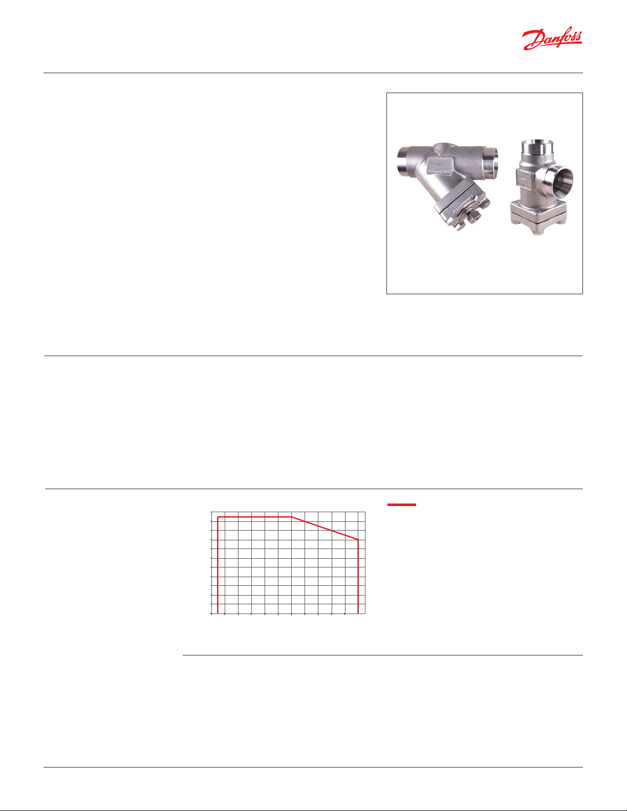
Check & stop valves SCA-X SS
Check Valves CHV-X SS
Strainers FIA SS
Pressure regulating valves OFV-SS
Gauge valves SNV-SS
Solenoid valves EVRS/EVRST
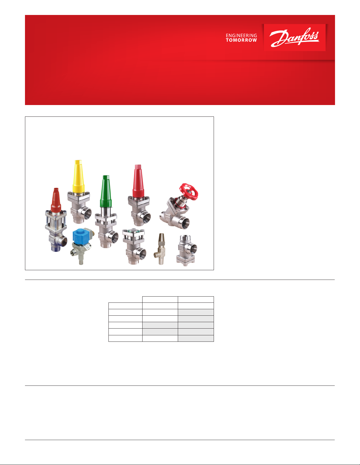
Danfoss Industrial Refrigeration extends a range of
stainless steel valves for special
application requirements.
The valve range includes for valve sizes
DN 15 mm (1/2 in.) to DN 125 mm (5 in.) in angleway
and straight execution and includes:
The range has been extended to meet the
increased demand brought about by
1. the need for higher protection of external
surfaces on valves and fittings
2. the need to meet developments in the way
that plants are being designed.
In certain specific areas such as outdoor
applications and corrosive atmospheres, such as
coastal installations, there is a need for high surface
protection to prevent failure due to corrosion.
Today's food safety standards often call for daily
treatment with detergents to protect against
bacteria growth, again producing a need for high
surface protection.
Features
© Danfoss | DCS (ms) | 2020.01
• Optional accessories:
SVA-S/L SS X X
REG-SA/SB SS X
SCA-X SS X
CHV-X SS
FIA SS
OFV-SS X
Vented cap Handwheel
• Designed to give favourable flow conditions.
• Internal backseating enables replacement
of the spindle seal whilst the valve is active, i.e.
under pressure (SVA-S/L SS, REG-SA/SB SS,
SCA-X SS, OFV-SS).
• Housing is made of special cold resistant stainless
steel approved for low temperature operations.
• Easy to disassemble for inspection and service.
• SVA-S/L SS Shut-off valves can accept flow in
either direction.
• Compact and light valves for easy handling and
installation.
• Classification: DNV, CRN, BV, EAC etc.
To get an updated list of certification on the
products please contact your local Danfoss Sales
Company.
AI235186440137en-US1101 | 1
Page 2

Data sheet | Stainless Steel Valves 15 (½ in.) - 125 ( 5 in.)
Contents Page
Shut-off valves SVA-S/L SS:
Features SVA-S/L SS ................................................................................................3
Pressure and temperature range....................................................................................3
Technical data .....................................................................................................3
Design.............................................................................................................4
Connections .......................................................................................................4
Material specification ..............................................................................................5
Dimensions and weights ...........................................................................................9
Ordering......................................................................................................... 12
Hand-operated regulating valves REG-SA SS and REG-SB SS:
Features REG-SA SS and REG-SB SS................................................................................ 14
Pressure and temperature range.................................................................................. 14
Technical data ...................................................................................................14
Design........................................................................................................... 15
Connections ..................................................................................................... 15
Computation and selection....................................................................................... 16
Material specification ............................................................................................ 22
Dimensions and weights ......................................................................................... 23
Ordering......................................................................................................... 24
Check & stop valves and check valves SCA-X SS and CHV-X SS:
Features SCA-X SS and CHV-X SS.................................................................................. 26
Pressure and temperature range.................................................................................. 26
Technical data ...................................................................................................26
Design........................................................................................................... 27
Connections ..................................................................................................... 27
Material specification ............................................................................................ 28
Dimensions and weights ......................................................................................... 29
Ordering......................................................................................................... 30
Strainers FIA SS:
Features FIA SS................................................................................................... 31
Pressure and ....................................................................................................31
temperature range............................................................................................... 31
Technical data ...................................................................................................31
Design........................................................................................................... 32
Connections ..................................................................................................... 32
Selection of strainer size.......................................................................................... 33
Material specification ............................................................................................ 34
Dimensions and weights ......................................................................................... 35
Ordering......................................................................................................... 36
Pressure regulating valves OFV-SS:
Features OFV-SS..................................................................................................37
Technical data ...................................................................................................37
Design........................................................................................................... 38
Connections ..................................................................................................... 38
Material specification ............................................................................................ 39
Dimensions and weights ......................................................................................... 40
Ordering......................................................................................................... 41
Gauge valve SNV-SS:
Features SNV-SS..................................................................................................42
Technical data ...................................................................................................42
Design........................................................................................................... 42
Connections ..................................................................................................... 42
Material specification ............................................................................................ 43
Dimensions and weights ......................................................................................... 44
Ordering......................................................................................................... 44
Solenoid valves EVRS and EVRST:
Features EVRS and EVRST......................................................................................... 45
Technical data ...................................................................................................45
Design/Function ................................................................................................. 47
Material specification ............................................................................................ 48
Dimensions and weights ......................................................................................... 49
Ordering......................................................................................................... 50
© Danfoss | DCS (ms) | 2020.01
AI235186440137en-US1101 | 2
Page 3
Data sheet | Stainless Steel Valves 15 (½ in.) - 125 ( 5 in.)
Pressure
Temperature
psi
bar
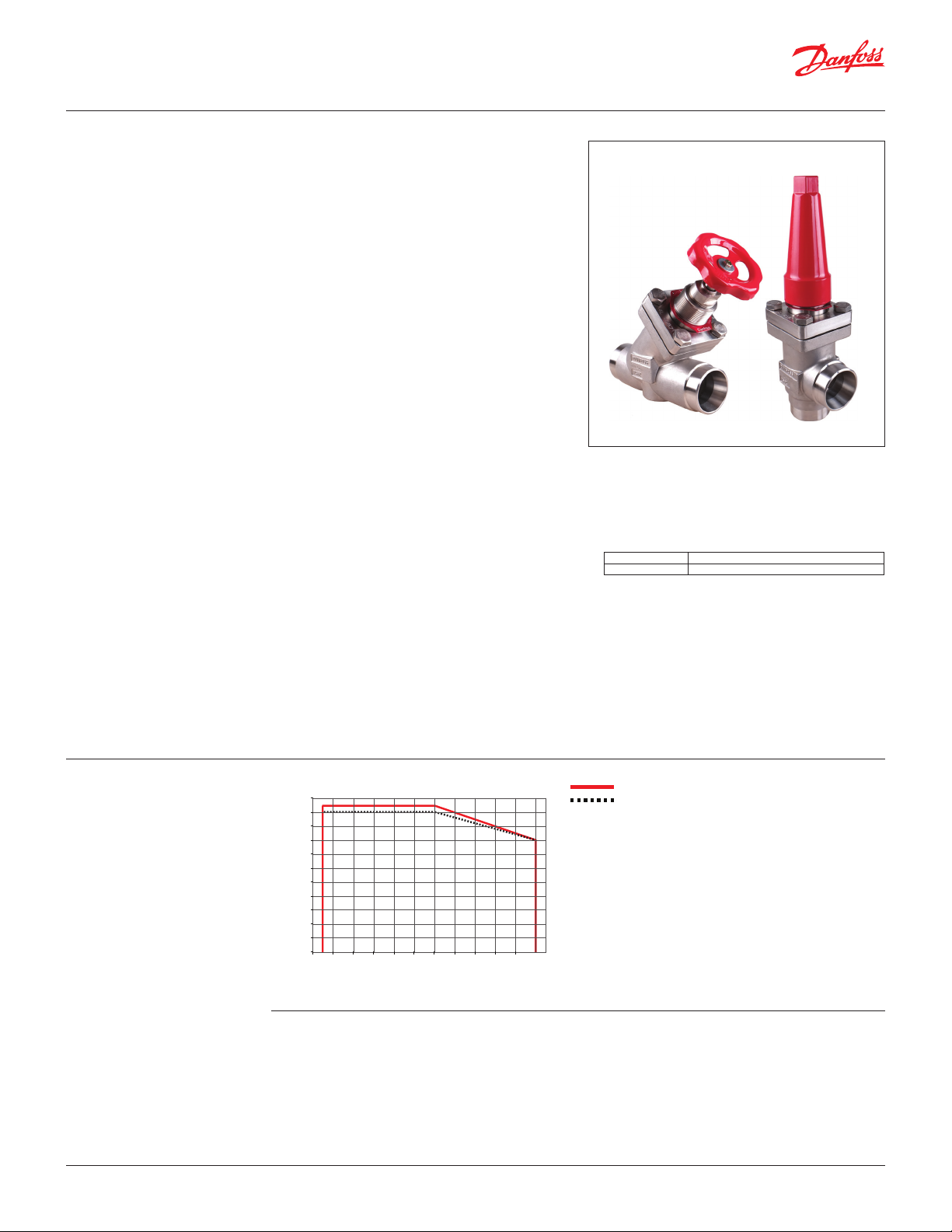
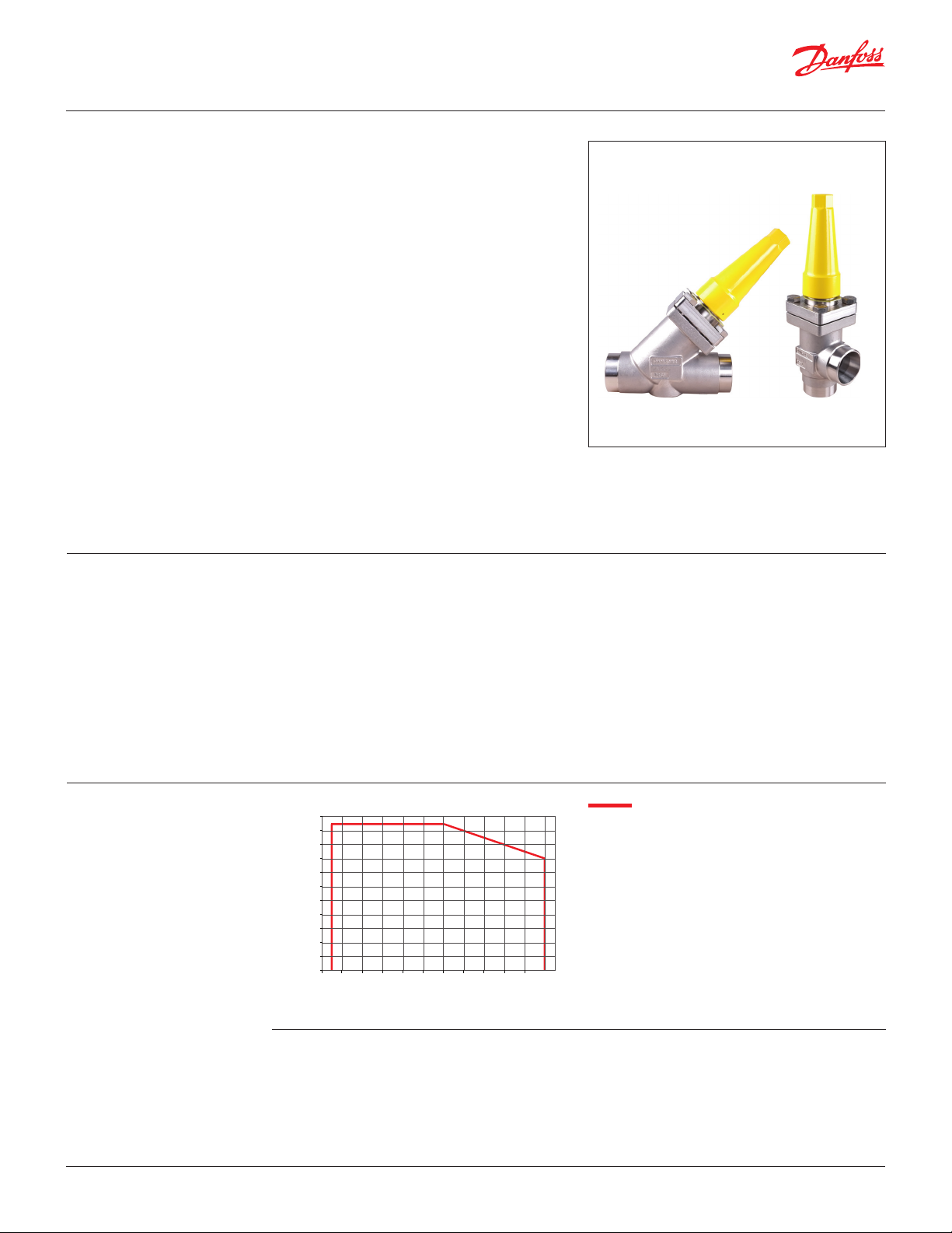
Shut-off valves
SVA-S/L SS
Features
SVA-S/L SS
In certain specific areas such as outdoor
applications and corrosive atmospheres, such
as coastal installations, there is a need for high
surface protection to prevent failure due to
corrosion.
Today's food safety standards often call for daily
treatment with detergents to protect against
bacteria growth, again producing a need for high
surface protection.
SVA-S/L SS are angleway and straightway
stainless steel shut-off valves, which are designed
to meet all industrial refrigeration application
requirements.
The valves are designed to give favourable
flow characteristics and are easy to dismantle
and repair when necessary. The valve cone is
designed to ensure perfect closing.
• Applicable to HCFC, HFC, R717 (Ammonia), R744
(CO2) and all flammable refrigerants.
• Optional accessories:
– Heavy duty industrial hand wheel for
frequent operation.
– Cap for infrequent operation.
• Available in angleway and straightway versions
with Standard neck or Long neck (DN 15 to
DN 40) for insulated systems.
• Designed to give favourable flow conditions.
• Internal backseating enables replacement
of the spindle seal whilst the valve is active, i.e.
under pressure.
• Housing is made of stainless steel approved for
low temperature operations.
• Easy to disassemble for inspection and service.
• SVA-S/L SS shut-off valves can accept flow in
either direction.
• Butt-weld DIN and ANSI connections.
• Maximum allowable working pressure and
temperature range:
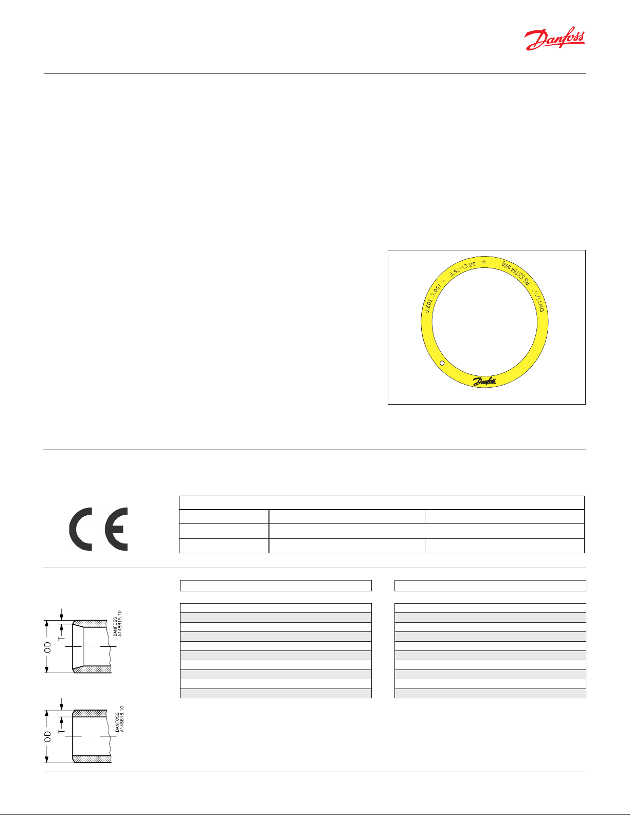
DN 15-65 52 bar / 754 psi at -60 – 50 °C / -76 – 122 °F
DN 80-125 50 bar / 725 psi at -60 – 50 °C / -76 – 122 °F
For SVA-S/L SS see the relation between PS and
temperature in the below curve.
• Tem perature range:
-60 – 150 °C / -76 – 302 °F.
• Compact and light valves for easy handling and
installation.
• Classification: DNV, CRN, BV, EAC etc.
To get an updated list of certification on the
products please contact your local Danfoss Sales
Company.
Pressure and
temperature range
Technical data • Refrigerants
798
55
725
50
653
45
580
40
508
35
435
30
363
25
Pressure
290
20
218
15
145
10
73
5
0
0
-70
-50-30 -101030507090 110 130 150
-94-58 -22145086 122 158 194 230 266 302
˚C
˚F
• Pressure range
Applicable to HCFC, HFC, R717 (Ammonia),
R744 (CO2) and all flammable refrigerants.
SVA-S/L SS DN15-DN65
SVA-S SS DN80 - DN125
The valves are designed for max. working
pressure 52 bar g / 754 psi g.
For further information please contact your
local Danfoss Sales Company.
© Danfoss | DCS (ms) | 2020.01
• Temperature Range
-60 – 150 °C / -76 – 302 °F.
AI235186440137en-US1101 | 3
Page 4
Data sheet | Stainless Steel Valves 15 (½ in.) - 125 ( 5 in.)
Design
Connections
Available with the following connections:
• Butt-weld DIN (EN 10220)
DN 15 – 125 (½ – 5 in.)
• Butt-weld ANSI (B 36.19M)
DN 15 – 100 (½ – 4 in.)
Housing
Made of stainless steel approved for low
temperature operations.
Valve cone
The valve cone can be turned on the spindle, thus
there will be no friction between the cone and
the seat, when the valve is opened and closed. A
teflon tightening ring provides
perfect sealing at a minimum closing
momentum.
Spindle
Made of polished stainless steel, ideal for
O-ring sealing. Furthermore, parts of the
spindle are heat treated to obtain
anti-abrasive / adhesive properties.
Packing gland
The stainless steel packing gland comprises
a spring loaded seal packing gland which
ensures a perfect tightness in the range:
-60 – 150 °C / -76 – 302 °F.
The packing glands are equipped with a scraper
ring to prevent penetration of dirt and ice into
the packing gland.
Pressure Equipment Directive (PED)
The stainless steel valves are approved and
CE marked in accordance with the Pressure
Equipment Directive - 97/23/EC.
Installation
It is recommended that the valves be installed in
the direction of flow indicated by the arrow on
the valve body. The valve can be installed in the
opposite direction but this slightly reduces the
kv-value (Cv-value).
The valve is designed to withstand high internal
pressure. However, the piping system in general
should be designed to avoid liquid traps and
reduce the risk of hydraulic pressure caused by
thermal expansion.
For further information refer to installation
instructions for SVA-S/L SS.
@
–
6
0
°
C
\
–
7
6
°
F
1
5
0
°
C
\
3
0
2
°
F
g
i
s
p
5
2
7
/
0
5
S
P
”
3
/
0
8
N
D
S
S
S
-
A
V
S
E
V
L
A
V
P
O
T
S
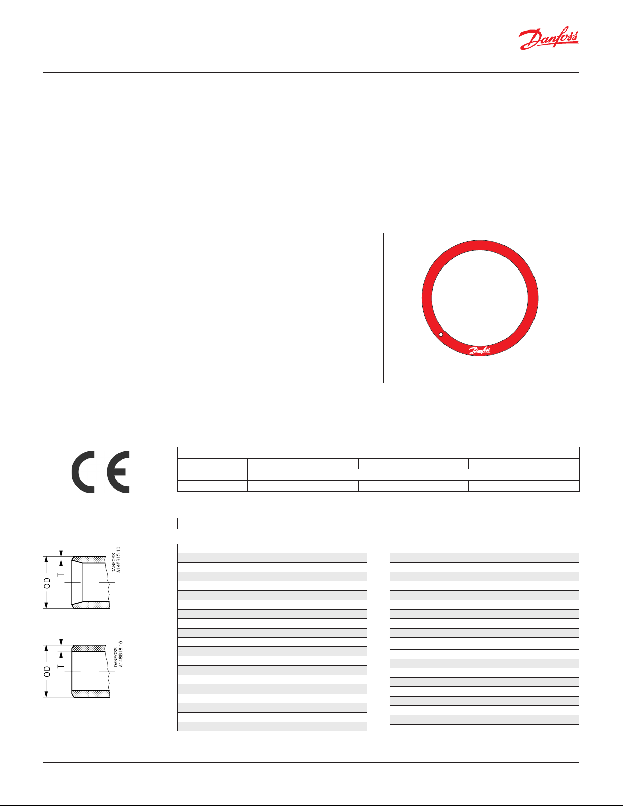
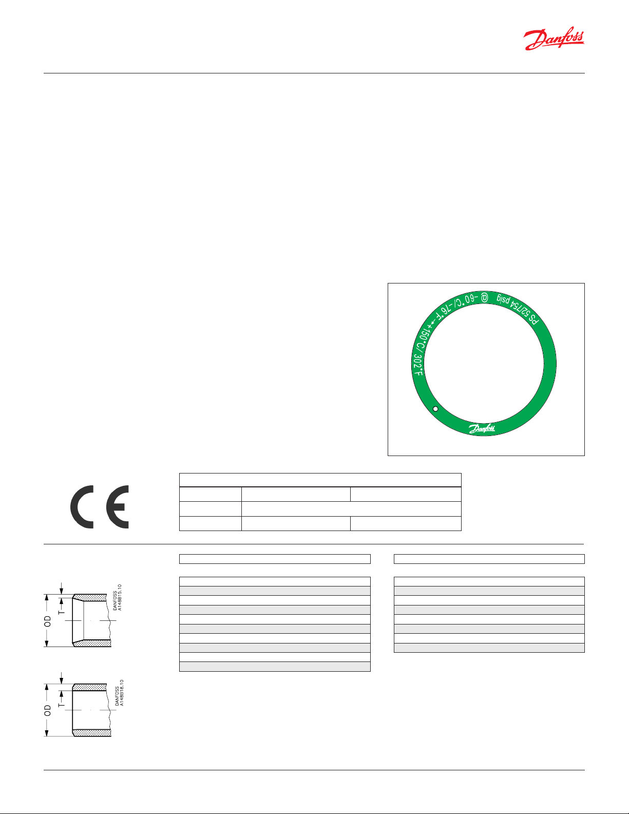
Example of Marking Ring
Connections
DIN
ANSI
SVA-S/L SS
Nominal bore DN≤ 25 mm (1 in.) DN32-80 mm (1 ¼ – 3 in.) DN100 – 125 mm (4 – 5 in.)
Classified for Fluid group I
Category Article 3, paragraph 3 II III
Size OD T
Butt-weld DIN (EN 10220)
15 mm 21.3 2.3
½ in. 0.839 0.091
20 mm 26.9 2.3
¾ in 1.059 0.091
25 mm 33.7 2.6
1 in. 1.327 0.103
32 mm 42.4 2.6
1 ¼ in. 1.669 0.102
40 mm 48.3 2.6
1 ½ in. 1.902 0.103
50 mm 60.3 2.9
2 in. 2.37 0.11
65 mm 76.1 2.9
2 ½ in. 3 0.11
80 mm 88.9 3.2
3 in. 3.50 0.13
100 mm 114.3 3.6
4 in. 4.50 0.14
125 mm 139.7 4.0
5 in. 5.50 0.16
Size OD T
Butt-weld ANSI B 36.19M, SCHEDULE 40
15 mm 21.3 2.8
½ in. 0.839 0.11
20 mm 26.9 2.9
¾ in 1.06 0.11
25 mm 33.7 3.5
1 in. 1.33 0.14
32 mm
1 ¼ in. 1.67 0.14
40 mm 48.3 3.7
1 ½ in. 1.9 0.15
42.4 3.6
Butt-weld ANSI B 36.19M, SCHEDULE 10
50 mm 60.3 2.8
2 in. 2.37 0.11
65 mm 73 3.1
2 ½ in. 2.87 0.12
80 mm 88.9 3.1
3 in. 3.5 0.12
100 mm 114.3 3.1
4 in. 4.5 0.12
© Danfoss | DCS (ms) | 2020.01
AI235186440137en-US1101 | 4
Page 5
Data sheet | Stainless Steel Valves 15 (½ in.) - 125 ( 5 in.)
Danfoss
M148B0035_1
M148B0038_1
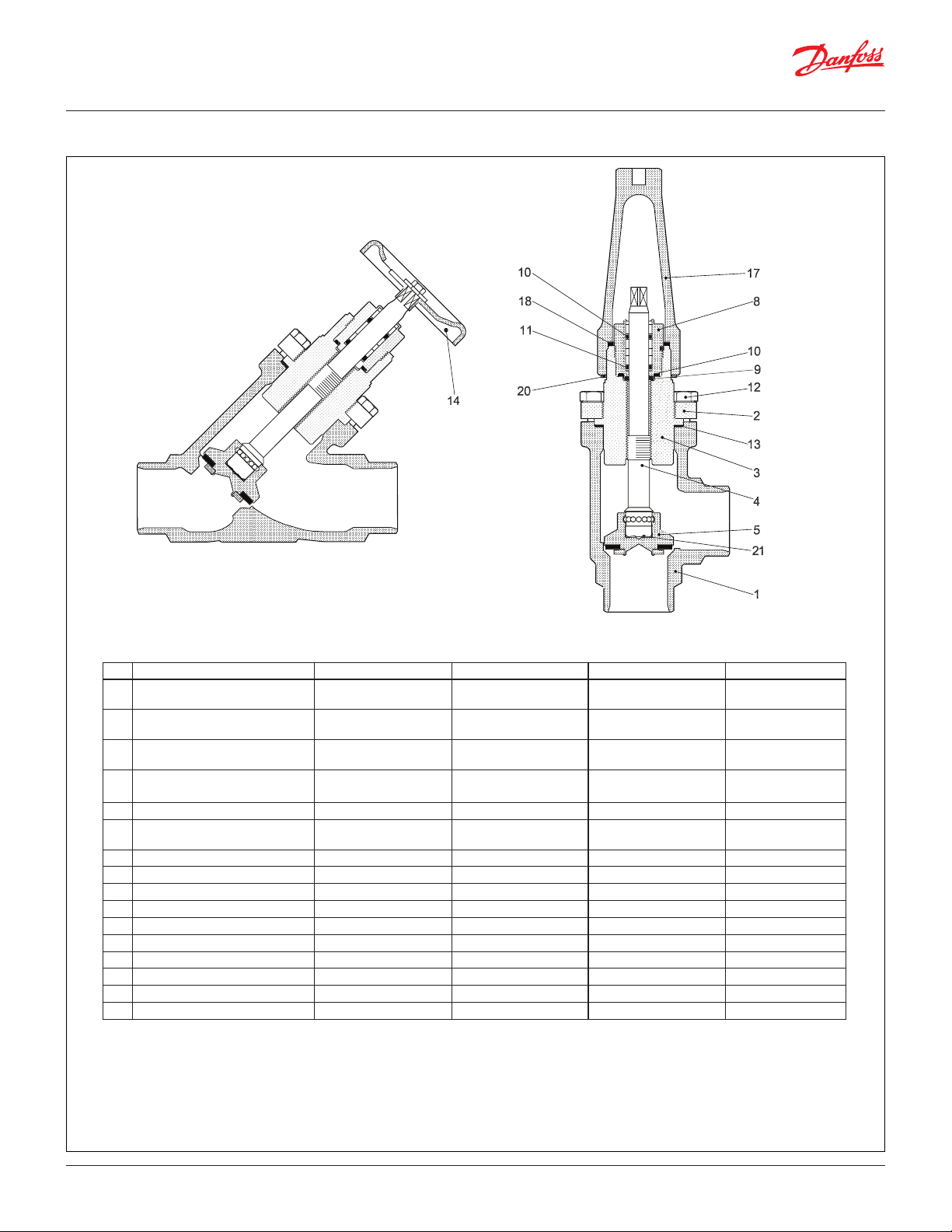
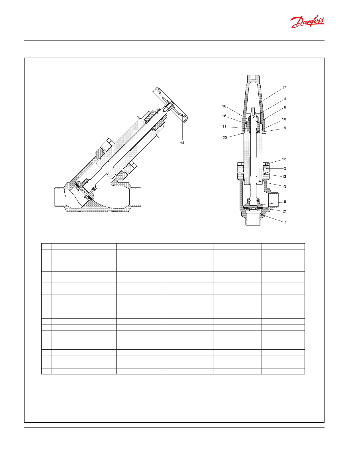
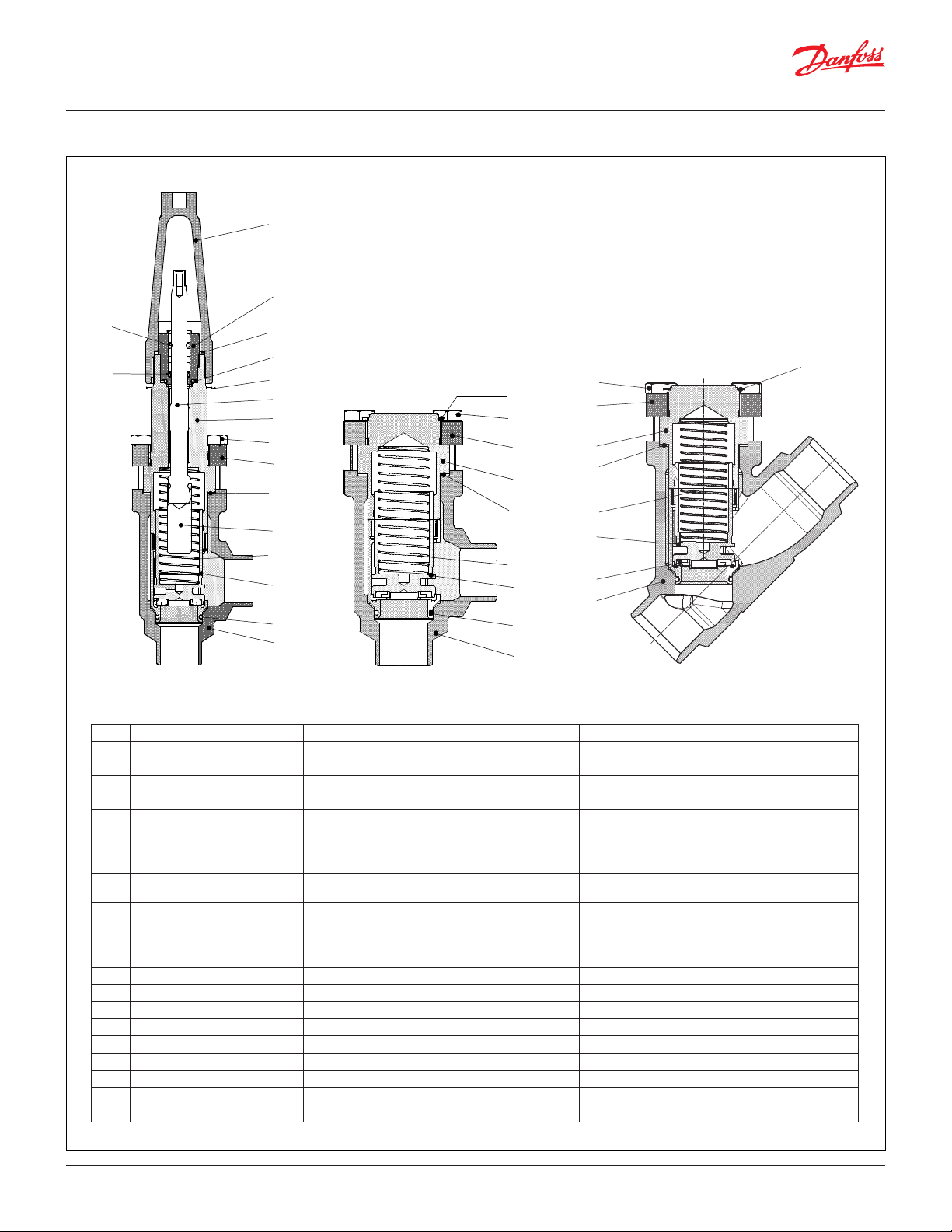
Material specification
SVA-S SS 15 – 40 (½ – 1 ½ in.)
Danfoss
No. Part Material EN ISO ASTM
1 Housing Stainless steel GX5CrNi19-10
AISI 304
EN10213-4
2 Bonnet, Flange Stainless steel X5CrNi18-10
AISI 304
EN10088
3 Bonnet, Insert Stainless steel X8CrNiS18-9
AISI 303
DIN 17440
4 Spindle
Stainless steel X8CrNiS18-9
Type 17, 683/13 AISI 303
DIN 17440
5 Cone Steel
8 Packing gland Stainless steel X8CrNiS18-9
10088
Type 17
683/13
AISI 303
9 Packing washer Aluminium
10 O-ring Cloroprene (Neoprene)
11 Spring loaded Teflon ring PTFE
12 Bolts Stainless steel A2-70 A2-70 Type 308
13 Gasket Fiber, Non-asbestos
14 Handwheel Steel
17 Cap Aluminium
18 Gasket for cap Nylon
20 Identification ring Stainless steel
21 Disk spring Steel
© Danfoss | DCS (ms) | 2020.01
AI235186440137en-US1101 | 5
Page 6
Data sheet | Stainless Steel Valves 15 (½ in.) - 125 ( 5 in.)
M148B0040_1
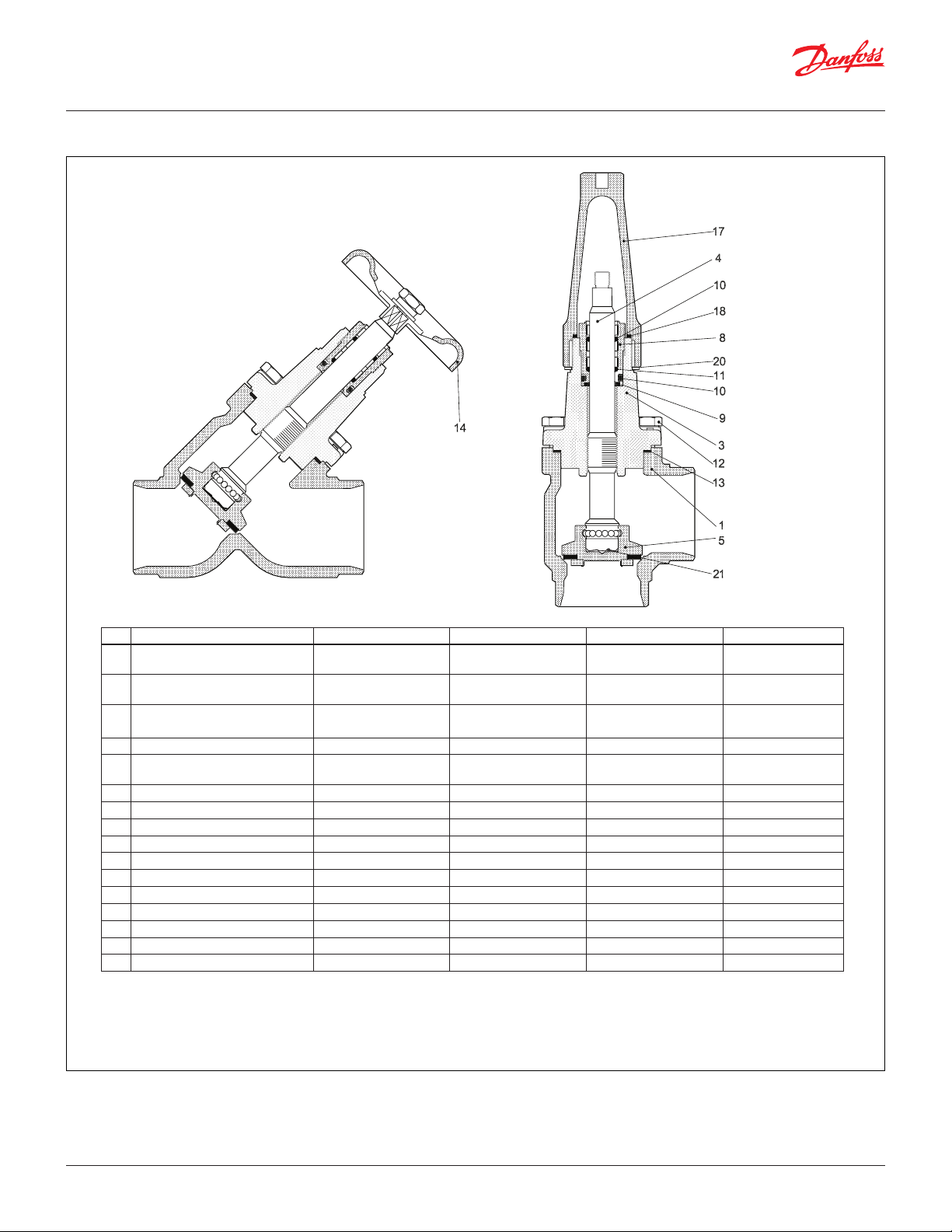
Material specification
SVA-L SS 15 – 40 (½ – 1 ½ in.)
Danfoss
s
No. Part Material EN ISO ASTM
1 Housing Stainless steel GX5CrNi19-10
AISI 304
EN10213-4
2 Bonnet, Flange Stainless steel X5CrNi18-10
AISI 304
EN10088
3 Bonnet, Insert Stainless steel X8CrNiS18-9
AISI 303
DIN 17440
4 Spindle
Stainless steel X8CrNiS18-9
Type 17, 683/13 AISI 303
DIN 17440
5 Cone Steel
8 Packing gland Stainless steel X8CrNiS18-9
10088
Type 17
683/13
AISI 303
9 Packing washer Aluminium
10 O-ring Cloroprene (Neoprene)
11 Spring loaded Teflon ring PTFE
12 Bolts Stainless steel A2-70 A2-70 Type 308
13 Gasket Fiber, Non-asbestos
14 Handwheel Steel
17 Cap Aluminium
18 Gasket for cap Nylon
20 Identification ring Stainless steel
21 Disk spring Steel
© Danfoss | DCS (ms) | 2020.01
AI235186440137en-US1101 | 6
Page 7
Data sheet | Stainless Steel Valves 15 (½ in.) - 125 ( 5 in.)
M148B0039_1
M148B0036_1
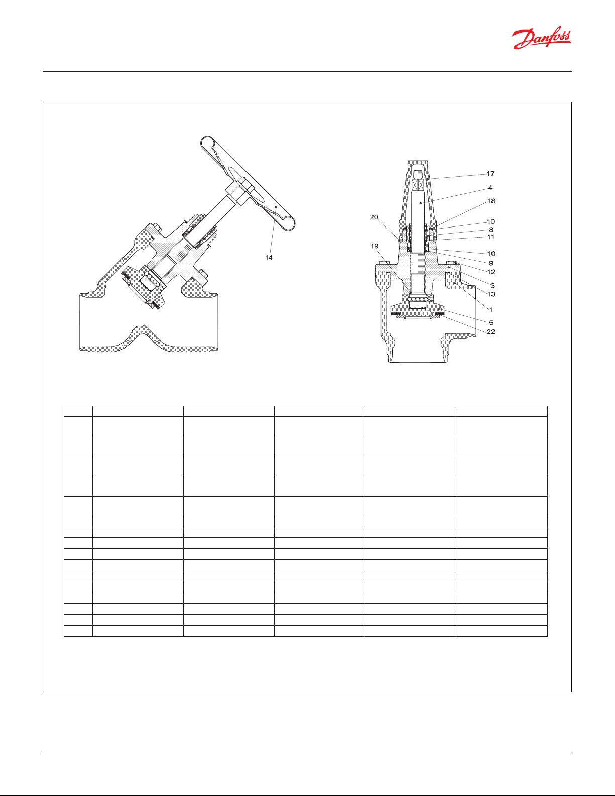
Material specification
SVA-S SS 50 – 65 (2 – 2 ½ in.)
Danfoss
Danfoss
No. Part Material EN ISO ASTM
1 Housing Stainless steel GX5CrNi19-10
AISI 304
EN10213-4
3 Valve bonnet Stainless steel GX5CrNi19-10
AISI 304
EN10213-4
4 Spindle
Stainless steel X8CrNiS18-9
Type 17, 683/13 AISI 303
DIN 17440
5 Cone Steel
8 Packing gland Stainless steel X8CrNiS18-9
10088
Type 17
683/13
AISI 303
9 Packing washer Aluminium
10 O-ring Cloroprene (Neoprene)
11 Spring loaded Teflon ring PTFE
12 Bolts Stainless steel A2-70 A2-70 Type 308
13 Gasket Fiber, Non-asbestos
14 Handwheel Steel
17 Cap Aluminium
18 Gasket for cap Nylon
19 Locking nut Steel
20 Identification ring Stainless steel
21 Disk spring Steel
© Danfoss | DCS (ms) | 2020.01
AI235186440137en-US1101 | 7
Page 8
Data sheet | Stainless Steel Valves 15 (½ in.) - 125 ( 5 in.)
Danfoss
M148B0096_1
M148B0006_1
Material specification
SVA-S SS 80 – 125 (3 – 5 in.)
Danfoss
No. Par t Material EN ISO ASTM
1 Housing Stainless steel GX5CrNi19-10
AISI 304
EN10213-4
3 Valve bonnet Stainless steel GX5CrNiMo19-11-2
AISI 304
EN10213-4
4 Spindle
Stainless steel X5CrNi18-10
Type 17, 683/13 AISI 303
DIN 17440
5 Cone
Cone seal
8 Packing gland Stainless steel X8CrNiS18-9
Steel
Teflon (PTFE)
10088
Type 17
R 683/13
AISI 303
9 Packing washer Aluminium
10 O-ring Cloroprene (Neoprene)
11 Spring loaded Teflon ring PTFE
12 Bolts Stainless steel A2-70 A2-70 Type 308
13 Gasket Fiber, Non-asbestos
14 Hand wheel Steel
17 Cap Aluminium
18 Gasket for cap Nylon (PA 6)
19 Soft backseat Teflon (PTFE)
20 Identification ring Stainless steel
22 Disk spring Steel
© Danfoss | DCS (ms) | 2020.01
AI235186440137en-US1101 | 8
Page 9
Data sheet | Stainless Steel Valves 15 (½ in.) - 125 ( 5 in.)
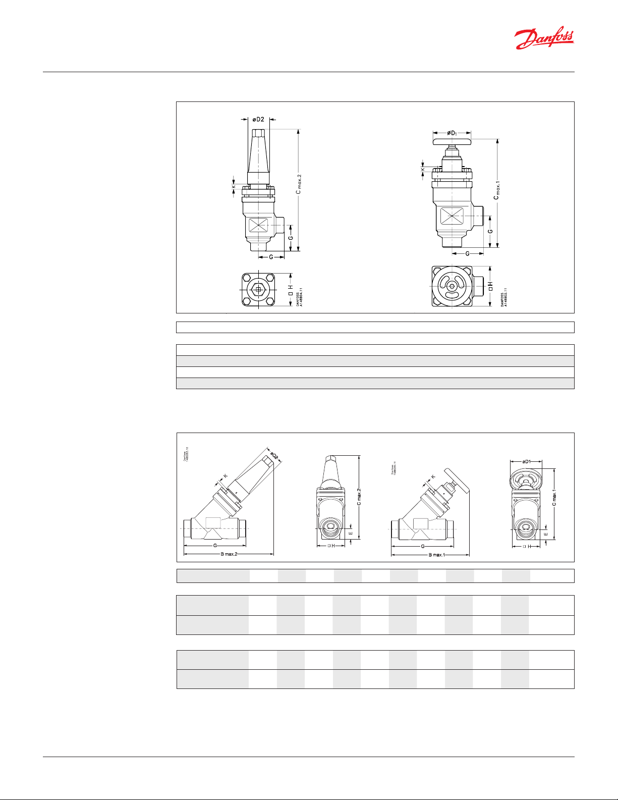
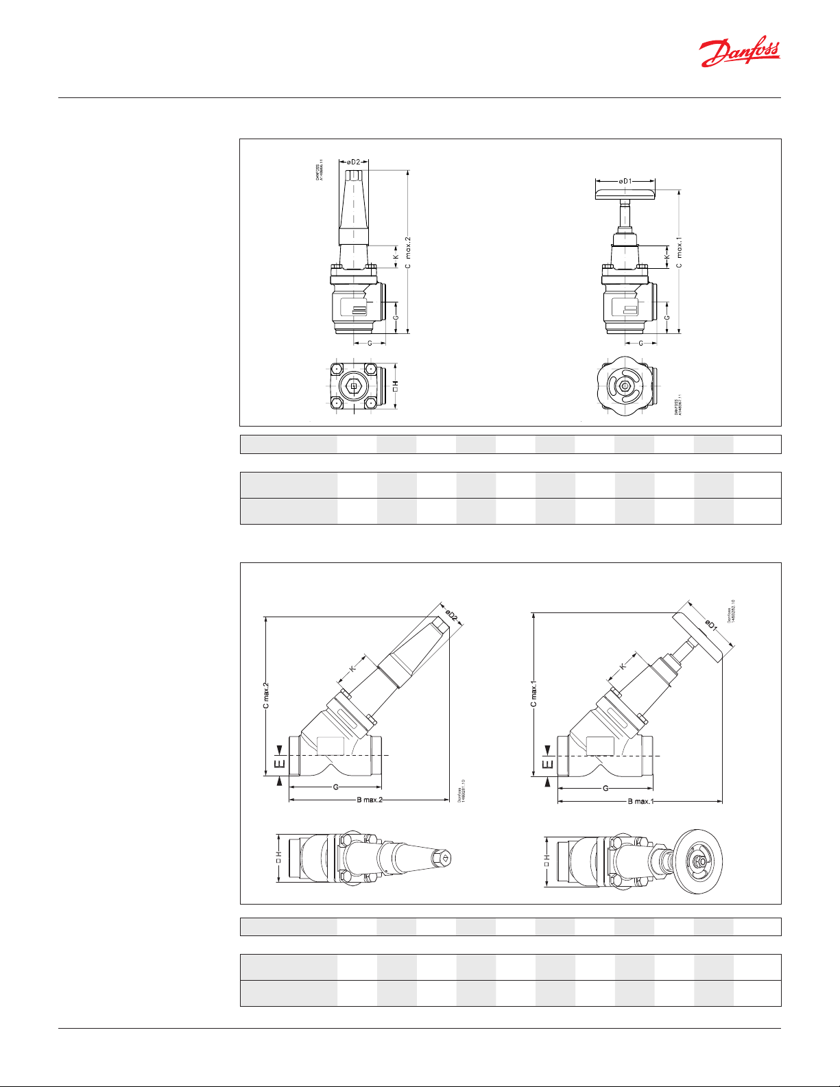
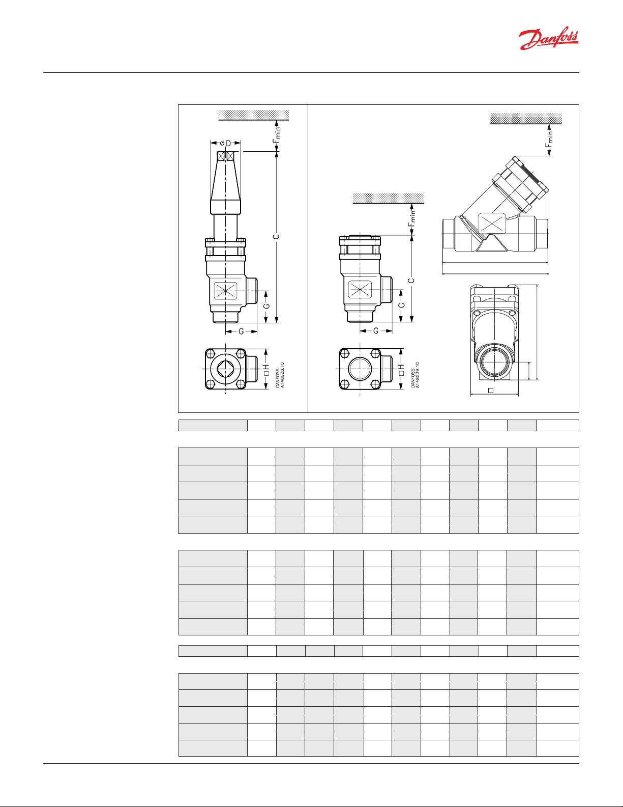
Dimensions and weights
SVA S SS 15 - 40 (½ – 1 ½ in. ) in angleway version with cap / hand wheel
SVA-xx x x ANG CAP
Valve size K C
max .1Cmax .2
G ØD1ØD
SVA-S SS
SVA-S SS 15 – 20 mm 4 178 189 45 60 38 60 1.4 kg
SVA-S SS 1/2 – 3/4" in. 0.16 7.00 7.44 1.77 2.36 1.5 2.36 3.1 lbs
SVA-S SS 25 – 40 mm 12 234 268 55 80 50 70 2.4 kg
SVA-S SS 1 – 11/2" in. 0.47 9.21 10.55 2.17 3.15 1.97 2.76 5.3 lbs
Specified weights are approximate values only.
SVA-xx x x ANG H-WHEEL
2
H
Weight
SVA-S/L SS 15 - 40 (½ – 1½ in. ) straightway version with cap / hand wheel
SVA-xx x x STR CAP
Valve size K C
max.1Cmax.2Bmax.1Bmax.2
SVA-xx x x STR H-WHEEL
E G ∅D1 ∅D
Weight
H
2
SVA-S SS
SVA-S SS 15 - 20 mm 4 146 141 160 156 20 120 60 38 60 2.0 kg
SVA-S SS (½ – ¾) in. 0.16 5.74 5.55 6.30 6.14 0.79 4.72 2.36 1.50 2.36 4.4 lb
SVA-S SS 25 – 40 mm 12 199 208 212 222 26 155 80 50 70 3.0 kg
SVA-S SS (1 – 1 ½) in. 0.47 7.83 8.19 8.35 8.74 1.02 6.10 3.15 1.97 2.76 6.6 lb
SVA-L SS
SVA-L SS 15 – 20 mm 63 188 184 202 198 20 120 60 38 60 2.0 kg
SVA-L SS (½ – ¾) in. 2.48 7.40 7.24 7.95 7.80 0.79 4.72 2.36 1.50 2.36 4.4 lb
SVA-L SS 25 – 40 mm 74 243 252 256 265 26 155 80 50 70 3.0 kg
SVA-L SS (1 – 1 ½) in. 2.91 9.57 9.92 10.08 10.43 1.02 6.10 3.15 1.97 2.76 6.6 lb
Specified weights are approximate values only.
© Danfoss | DCS (ms) | 2020.01
AI235186440137en-US1101 | 9
Page 10
Data sheet | Stainless Steel Valves 15 (½ in.) - 125 ( 5 in.)
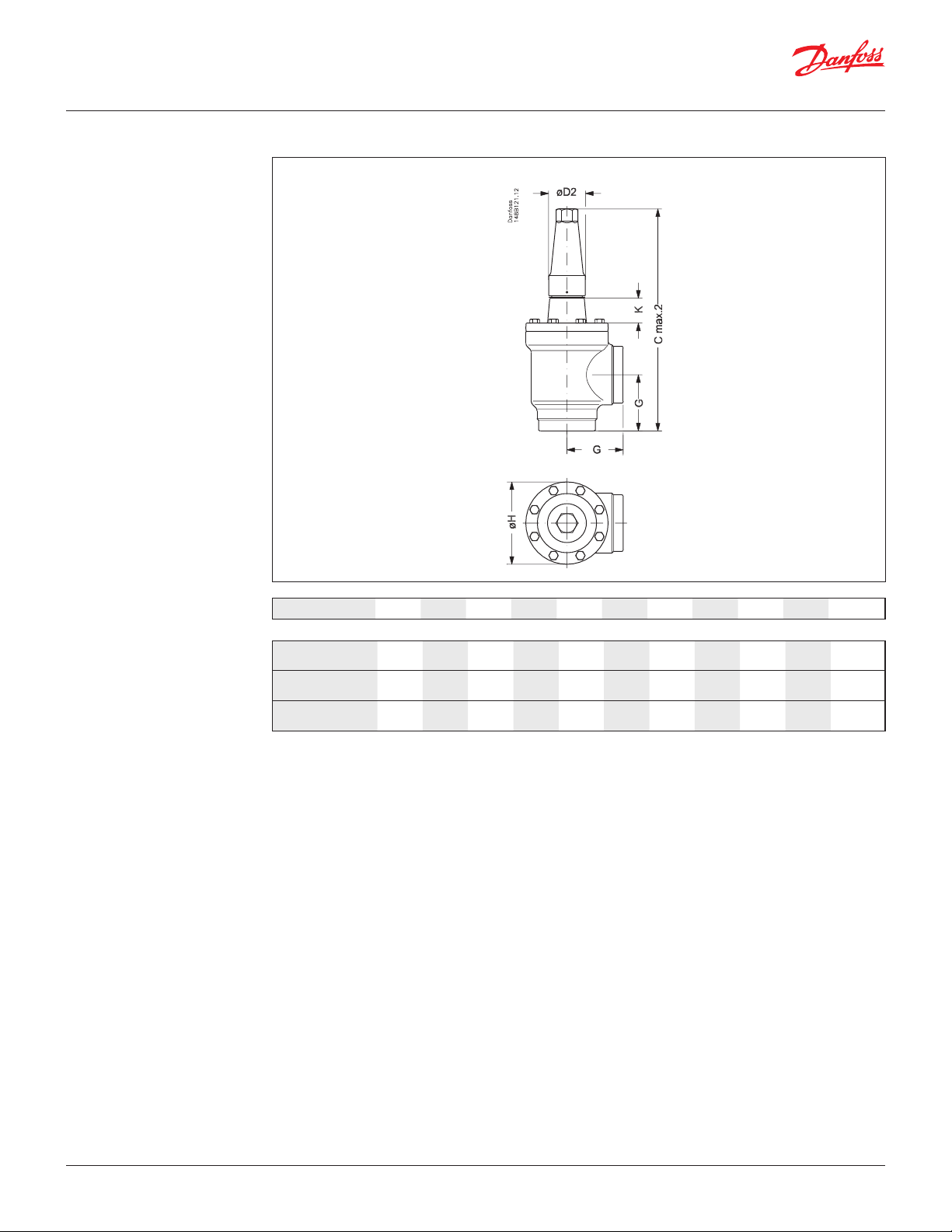
Dimensions and weights
SVA-S SS 50 – 65 (2 – 2 ½ in.) in angleway version with cap / hand wheel
SVA-xx x x ANG CAP
Valve size K C
max.1Cmax.2
SVA-xx x x ANG H-WHEEL
G ∅D1 ∅D2
H
Weight
SVA-S SS
SVA-S SS 50 mm 70 284 315 60 100 50 77 3.2 kg
SVA-S SS (2) in. 2.76 11.18 12.40 2.36 3.94 1.97 3.03 7.1 lb
SVA-S SS 65 mm 70 310 335 70 100 50 90 4.8 kg
SVA-S SS (2 ½) in. 2.76 12.20 13.19 2.76 3.94 1.97 3.54 10.6 lb
Specified weights are approximate values only.
SVA-S SS 50 – 65 (2 – 2 ½ in.) in straightway version with cap / hand wheel
SVA-xx x x STR CAP
SVA-xx x x STR H-WHEEL
© Danfoss | DCS (ms) | 2020.01
Valve size K B
max.1Bmax.2Cmax.1Cmax.2
E G ∅D1 ∅D
Weight
H
2
SVA-S SS
SVA-S SS 50 mm 70 259 259 257 257 32 148 100 50 77 4.2 kg
SVA-S SS (2) in. 2.76 10.20 10.20 10.12 10.12 1.26 5.83 3.94 1.97 3.03 9.3 lb
SVA-S SS 65 mm 70 284 280 284 280 40 176 100 50 90 6.3 kg
SVA-S SS (2 ½) in. 2.76 11.18 11.02 11.18 11.02 1.57 6.93 3.94 1.97 3.54 13.9 lb
Specified weights are approximate values only.
AI235186440137en-US1101 | 10
Page 11
Data sheet | Stainless Steel Valves 15 (½ in.) - 125 ( 5 in.)
Dimensions and weights SVA-S SS 80 – 125 (3 – 5 in.) angleway version with cap / hand wheel
SVA-xx x x ANG CAP
Valve size K C
SVA-S SS
SVA-S SS 80
SVA-S SS (3)mmin.
SVA-S SS 100
SVA-S SS (4)mmin.
SVA-S SS 125
SVA-S SS (5)mmin.
Specified weights are approximate values only.
76
3.00
90
3.54
90
3.54
max.2
388
15.28
437
17.20
533
20.98
G ∅D1∅D2 ∅H Weight
90
3.54
106
4.17
128
5.04
200
7.87582.28
250
9.84582.28
315
12.40742.91
129
5.08
156
6.14
193
7.60
9.7 kg
21.4 lb
15.3 kg
33.7 lb
28.1 kg
61.9 lb
© Danfoss | DCS (ms) | 2020.01
AI235186440137en-US1101 | 11
Page 12
Data sheet | Stainless Steel Valves 15 (½ in.) - 125 ( 5 in.)
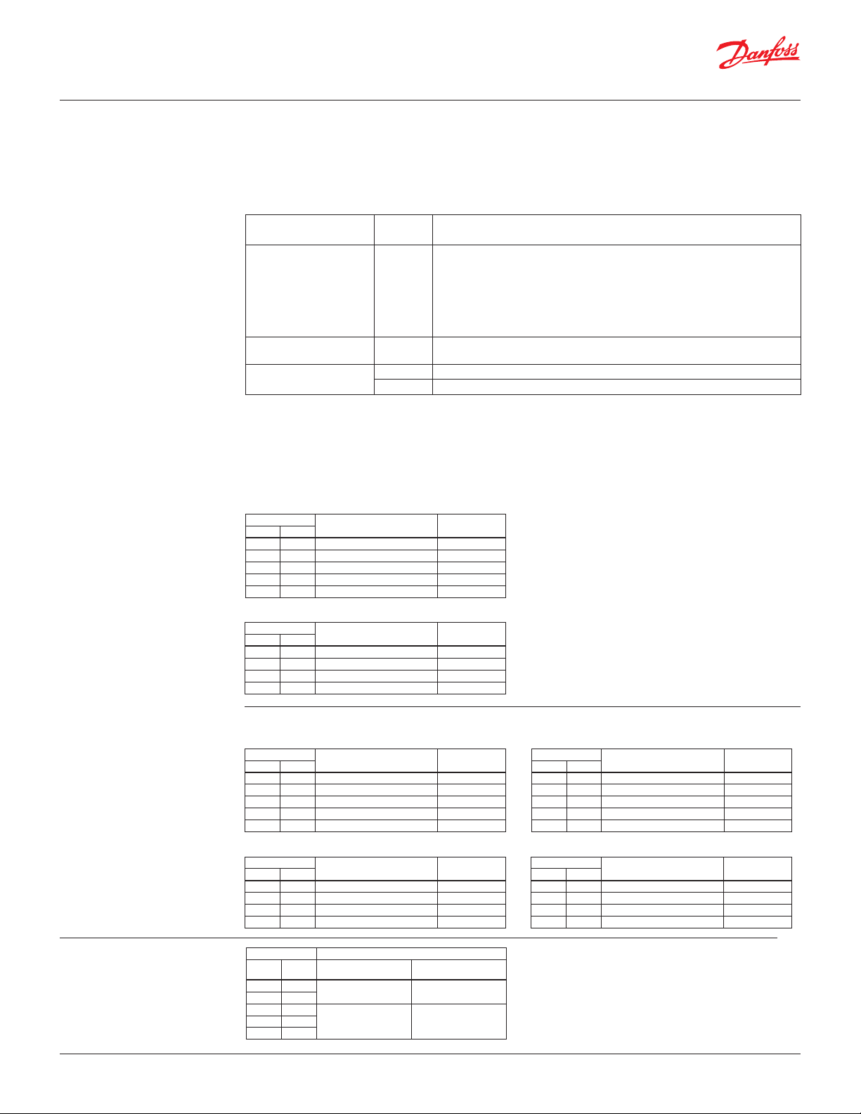
Ordering
Please note that the type codes only serve to
identify the valves, some of which may not form
part of the standard product range. For further
information please contact your local Danfoss Sales
Company.
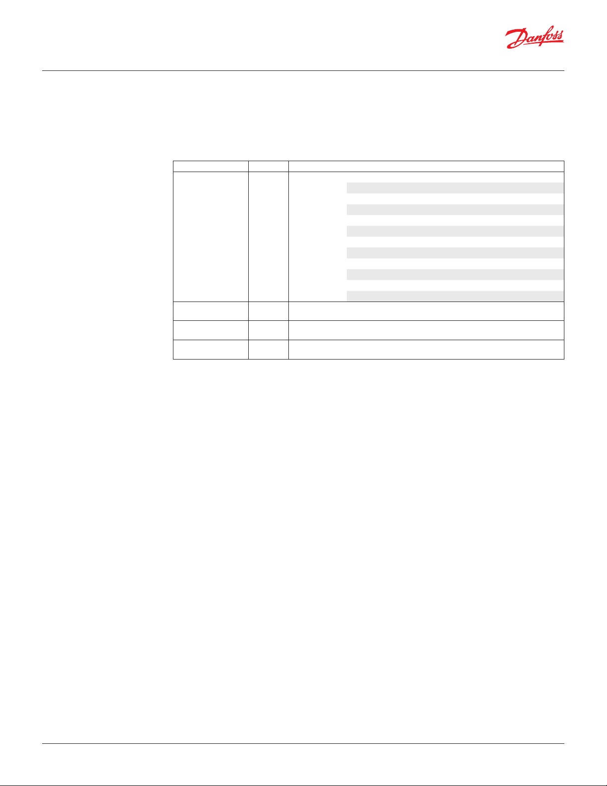
Type codes
Valve type SVA-S/L SS Shut-off valve
Nominal size in mm Available connections
(valve size measured
on the connection
diameter)
Connections D
Valve housing ANG
Other equipment H-WHEEL
15 DN 15 (½) x x
20 DN 20 (¾) x x
25 DN 25 (1) x x
32 DN 32 (1 ¼) x x
40 DN 40 (1 ½) x x
50 DN 50 (2) x x
65 DN 65 (2 ½) x x
80 DN 80 (3) x x
100 DN 100 (4) x x
125 DN 125 (5) x
A
STR
CAP
Butt-weld connection
Butt-weld connection
Angle flow
Straight flow
Hand wheel
Cap
D A
: DIN EN 10220
: ANSI B 36.19M
Important!
Where products need to be certified according
to specific certification societies or where higher
pressures are required, the relevant information
should be included at the time of order.
© Danfoss | DCS (ms) | 2020.01
AI235186440137en-US1101 | 12
Page 13
Data sheet | Stainless Steel Valves 15 (½ in.) - 125 ( 5 in.)
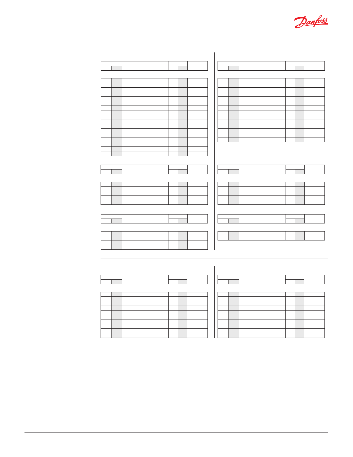
Ordering
Ordering SVA-S/L SS
Example:
SVA-S SS 20 DIN angleway with
hand wheel = 148B5377
Important!
Where products need to be certified
according to specific certification
societies or where higher pressures are
required, the relevant information should
be included at the time of order.
Size
mm in. bar psi
Type
MWP
Code
number
Butt-weld DIN (EN 10220)
15 ½ SVA-S SS 15 D ANG H-WHEEL 52 754 148B5289
15 ½ SVA-S SS 15 D ANG CAP 52 754 148B5290
20 ¾ SVA-S SS 20 D ANG H-WHEEL 52 754 148B5377
20 ¾ SVA-S SS 20 D ANG CAP 52 754 148B5378
25 1 SVA-S SS 25 D ANG H-WHEEL 52 754 148B5486
25 1 SVA-S SS 25 D ANG CAP 52 754 148B5487
32 1 ¼ SVA-S SS 32 D ANG H-WHEEL 52 754 148B5566
32 1 ¼ SVA-S SS 32 D ANG CAP 52 754 148B5567
40 1 ½ SVA-S SS 40 D ANG H-WHEEL 52 754 148B5646
40 1 ½ SVA-S SS 40 D ANG CAP 52 754 148B5647
50 2 SVA-S SS 50 D ANG H-WHEEL 52 754 148B5753
50 2 SVA-S SS 50 D ANG CAP 52 754 148B5754
65 2 ½ SVA-S SS 65 D ANG H-WHEEL 52 754 148B5847
65 2 ½ SVA-S SS 65 D ANG CAP 52 754 148B5848
80 3 SVA-S SS 80 D ANG CAP 50 725 148B5928
100 4 SVA-S SS 100 D ANG CAP 50 725 148B6032
125 5 SVA-S SS 125 D ANG CAP 50 725 148B6126
Size
mm in. bar psi
Type
MWP
Code
number
Butt-weld ANSI (B 36.19M SCHEDULE 40)
15 ½ SVA-S SS 15 A40 ANG CAP 52 754 148B5396
20 ¾ SVA-S SS 20 A40 ANG CAP 52 754 148B5395
25 1 SVA-S SS 25 A40 ANG CAP 52 754 148B6477
32 1 ¼ SVA-S SS 32 A40 ANG CAP 52 754 148B5595
40 1 ½ SVA-S SS 40 A40 ANG CAP 52 754 148B5683
Size
mm in. bar psi
Type
MWP
Code
number
Butt-weld ANSI (B 36.19M SCHEDULE 10)
50 2 SVA-S SS 50 D/A10 ANG CAP 52 754 148B5754
65 2 ½ SVA-S SS 65 A10 ANG CAP 52 754 148B6448
80 3 SVA-S SS 80 D/A10 ANG CAP 52 754 148B5928
100 4 SVA-S SS 100 A10 ANG CAP 52 754 148B6035
SVA-S SS StraightwaySVA-S SS Angleway
Size
mm in. bar psi
Type
Butt-weld DIN (EN 10220)
15 ½ SVA-S SS 15 D STR H-WHEEL 52 754 148B5291
15 ½ SVA-S SS 15 D STR CAP 52 754 148B5292
20 ¾ SVA-S SS 20 D STR H-WHEEL 52 754 148B5379
20 ¾ SVA-S SS 20 D STR CAP 52 754 148B5380
25 1 SVA-S SS 25 D STR H-WHEEL 52 754 148B5488
25 1 SVA-S SS 25 D STR CAP 52 754 148B5489
32 1 ¼ SVA-S SS 32 D STR H-WHEEL 52 754 148B5568
32 1 ¼ SVA-S SS 32 D STR CAP 52 754 148B5569
40 1 ½ SVA-S SS 40 D STR H-WHEEL 52 754 148B5648
40 1 ½ SVA-S SS 40 D STR CAP 52 754 148B5649
50 2 SVA-S SS 50 D STR H-WHEEL 52 754 148B5755
50 2 SVA-S SS 50 D STR CAP 52 754 148B5756
65 2 ½ SVA-S SS 65 D STR H-WHEEL 52 754 148B5849
65 2 ½ SVA-S SS 65 D STR CAP 52 754 148B5850
Size
mm in. bar psi
Type
Butt-weld ANSI (B 36.19M SCHEDULE 40)
15 ½ SVA-S SS 15 A40 STR CAP 52 754 148B5397
20 ¾ SVA-S SS 20 A40 STR CAP 52 754 148B5398
25 1 SVA-S SS 25 A40 STR CAP 52 754 148B5399
32 1 ¼ SVA-S SS 32 A40 STR CAP 52 754 148B5596
40 1 ½ SVA-S SS 40 A40 STR CAP 52 754 148B5684
Size
mm in. bar psi
Type
Butt-weld ANSI (B 36.19M SCHEDULE 10)
50 2 SVA-S SS 50 D/A10 STR CAP 52 754 148B5756
65 2 ½ SVA-S SS 65 A10 STR CAP 52 754 148B6449
MWP
MWP
MWP
number
number
number
Code
Code
Code
ANG = Angleway
STR = Straightway
CAP = Cap
H-WHEEL = Hand wheel
Size
mm in. bar psi
Type
MWP
number
Butt-weld DIN (EN 10220)
15 ½ SVA-L SS 15 D ANG H-WHEEL 52 754 148B6546
15 ½ SVA-L SS 15 D ANG CAP 52 754 148B6547
20 ¾ SVA-L SS 20 D ANG H-WHEEL 52 754 148B6550
20 ¾ SVA-L SS 20 D ANG CAP 52 754 148B6551
25 1 SVA-L SS 25 D ANG H-WHEEL 52 754 148B6554
25 1 SVA-L SS 25 D ANG CAP 52 754 148B6555
32 1 ¼ SVA-L SS 32 D ANG H-WHEEL 52 754 148B6558
32 1 ¼ SVA-L SS 32 D ANG CAP 52 754 148B6559
40 1 ½ SVA-L SS 40 D ANG H-WHEEL 52 754 148B6562
40 1 ½ SVA-L SS 40 D ANG CAP 52 754 148B6563
Code
SVA-L SS StraightwaySVA-L SS Angleway
Size
mm in. bar psi
Type
Butt-weld DIN (EN 10220)
15 ½ SVA-L SS 15 D STR H-WHEEL 52 754 148B6548
15 ½ SVA-L SS 15 D STR CAP 52 754 148B6549
20 ¾ SVA-L SS 20 D STR H-WHEEL 52 754 148B6552
20 ¾ SVA-L SS 20 D STR CAP 52 754 148B6553
25 1 SVA-L SS 25 D STR H-WHEEL 52 754 148B6556
25 1 SVA-L SS 25 D STR CAP 52 754 148B6557
32 1 ¼ SVA-L SS 32 D STR H-WHEEL 52 754 148B6560
32 1 ¼ SVA-L SS 32 D STR CAP 52 754 148B6561
40 1 ½ SVA-L SS 40 D STR H-WHEEL 52 754 148B6564
40 1 ½ SVA-L SS 40 D STR CAP 52 754 148B6565
MWP
number
Code
© Danfoss | DCS (ms) | 2020.01
AI235186440137en-US1101 | 13
Page 14
Data sheet | Stainless Steel Valves 15 (½ in.) - 125 ( 5 in.)
Pressure
Temperature
psi
bar
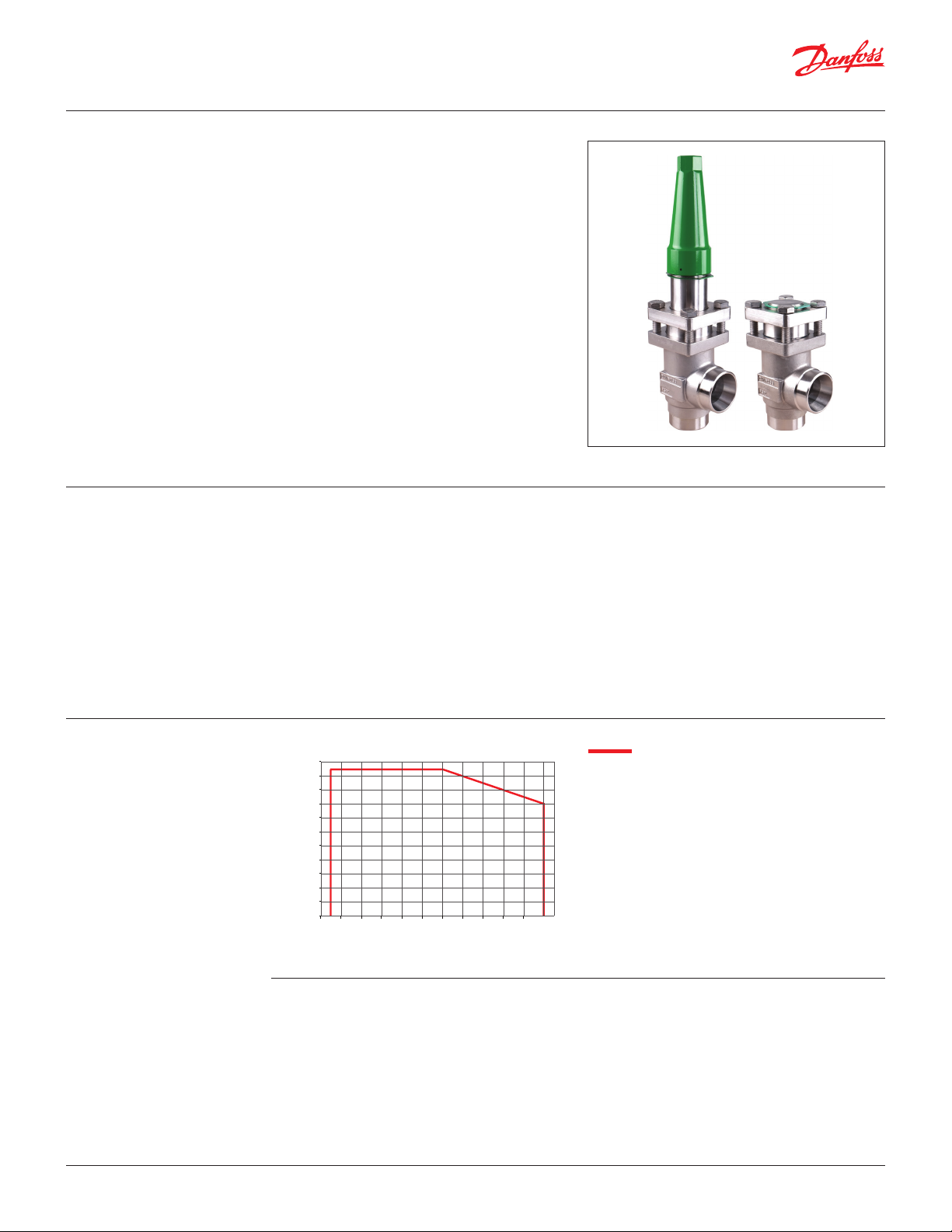
Hand-operated
regulating valves
REG-SA SS and REG-SB SS
Features
REG-SA SS and REG-SB SS
In certain specific areas such as outdoor
applications and corrosive atmospheres, such as
coastal installations, there is a need for high surface
protection to prevent failure due to corrosion.
Today's food safety standards often call for daily
treatment with detergents to protect against
bacteria growth, again producing a need for high
surface protection.
REG-SA SS and REG-SB SS are angle-way and
straight-way hand-operated regulating valves,
which act as normal stop valves in closed position.
The valves are designed to meet the strict
quality requirements on refrigerating
installations specified by the international
classification societies and are carefully
designed to present favourable flow
conditions and accurate linear characteristics.
The valves are equipped with vented cap and have
internal backseating enabling the spindle
seal to be replaced with the valve still under
pressure.
• Applicable to HCFC, HFC, R717 (Ammonia), R744
(CO2), Propane, Butane, Iso-Butane and Ethane.
R717 Heat Pump and Propylene applications
with replaced O-ring.
• Designed to give favourable flow conditions.
• Internal backseating enables replacement
of the spindle seal whilst the valve is active, i.e.
under pressure
• Housing is made of special cold resistant
stainless steel approved for low temperature
operations.
• Easy to disassemble for inspection and service.
• Butt-weld DIN and ANSI connections.
• Max. operating pressure:
52 bar g / 754 psig
• Tem perature range:
-60 – 150 °C / -76 – 302 °F.
• Compact and light valves for easy handling and
installation.
• Classification: DNV, CRN, BV, EAC etc.
To get an updated list of certification on the
products please contact your local Danfoss Sales
Company.
Pressure and
temperature range
Technical data • Refrigerants
798
55
725
50
653
45
580
40
508
35
435
30
363
25
Pressure
290
20
218
15
145
10
73
5
0
0
-70
-50-30 -101030507090 110 130 150
-94-58 -22145086 122 158 194 230 266 302
Temperature
˚C
˚F
• Temperature range
Applicable to HCFC, HFC, R717 (Ammonia), R744
(CO2), Propane, Butane, Iso-Butane and Ethane.
R717 Heat Pump and Propylene applications
with replaced O-ring.
For further information please contact your local
• Max working pressure
• Flow coefficients
Danfoss Sales Company.
© Danfoss | DCS (ms) | 2020.01
REG-SA SS/REG-SB SS DN15-DN40
-60 – 150 °C / -76 – 302 °F
52 bar g / 754 psi g
Flow coefficients for fully opened valves from
kv = 0.15 to 80 m3/h (Cv = 0.17 to 92.5 USgal/min).
AI235186440137en-US1101 | 14
Page 15
Data sheet | Stainless Steel Valves 15 (½ in.) - 125 ( 5 in.)
R
E
G
U
L
A
T
I
N
G
V
A
L
V
E
R
E
G
-
S
A
S
S
Design
Housing
Made of stainless steel approved for low
temperature operations.
Connections
Available with the following connections:
• Butt-weld DIN (EN 10220)
DN 15 - 40 (½ - 1½ in.)
• Butt-weld ANSI (B 36.19M)
DN 15 - 40 (½ - 1½ in.)
The cone
The valves are available in two different
versions – REG-SA SS with an A cone and REGSB SS with a B cone. The A cone is designed for
expansion lines, while the B cone is designed for
regulating purposes e.g. liquid lines.
The valve cone is designed to ensure perfect
regulation and provide an extensive regulating
area. Irrespective of the refrigerant used, it is easy
to obtain the correct capacity. A cone seal ring
provides perfect sealing at a minimum closing
momentum.
The valve cone can be turned on the spindle, thus
there will be no friction between the cone and the
seat when the valve is opened and closed.
Spindle
Made of polished stainless steel, ideal for
O-ring sealing. Furthermore, parts of the
spindle are heat treated to obtain
anti-abrasive/adhesive properties.
Packing gland - REG-SA SS and REG-SB SS
The stainless steel packing gland comprises
a spring loaded seal packing gland which
ensures a perfect tightness in the range:
-60 – 150 °C / -76 – 302 °F.
The packing glands are equipped with a scraper
ring to prevent penetration of dirt and ice into the
packing gland.
Installation
Install the valve with the spindle up or in horizontal
position. The flow must be directed towards the
cone.
The valve is designed to withstand high internal
pressure. However, the piping system in general
should be designed to avoid liquid traps and
reduce the risk of hydraulic pressure caused by
thermal expansion.
For further information refer to product instruction
for REG-SA SS and REG-SB SS.
Example of marking ring, REG-SA SS
Connections
DIN
ANSI
© Danfoss | DCS (ms) | 2020.01
Pressure Equipment Directive (PED)
REG-SA/SB SS valves are approved according to the European standard specified in the Pressure
Equipment Directive and are CE marked.
REG-SA SS and REG-SB SS valves
Nominal bore
Classified for Fluid group I
Category Article 3, paragraph 3 II
Size OD T
Butt-weld DIN (EN 10220)
15 mm 21.3 2.3
½ in. 0.839 0.091
20 mm 26.9 2.3
¾ in 1.059 0.091
25 mm 33.7 2.6
1 in. 1.327 0.103
32 mm 42.4 2.6
1¼ in. 1.669 0.102
40 mm 48.3 2.6
1½ in. 1.902 0.103
DN = < 25 mm (1 in.) DN32-40 mm (1¼ - 1½ in.)
Size OD T
Butt-weld ANSI B 36.19M, SCHEDULE 40
15 mm 21.3 2.8
½ in. 0.839 0.11
20 mm 26.9 2.9
¾ in 1.06 0.11
25 mm 33.7 3.5
1 in. 1.33 0.14
32 mm 42.4 3.6
1¼ in. 1.67 0.14
40 mm 48.3 3.7
1½ in. 1.9 0.15
AI235186440137en-US1101 | 15
Page 16
Data sheet | Stainless Steel Valves 15 (½ in.) - 125 ( 5 in.)
Computation and selection
Introduction
In refrigeration plants, regulating valves
are primarily used in liquid lines in order to
regulate the flow of refrigerant. The valves can,
however, also be used as expansion valves. From
a calculation point of view the two fields of
application are very different.
Normal flow is the term used to describe the
general case where the flow through the valve is
proportional to the square root of the pressure
drop across it and inversely proportional to the
density of the refrigerant (Bernouillis equation).
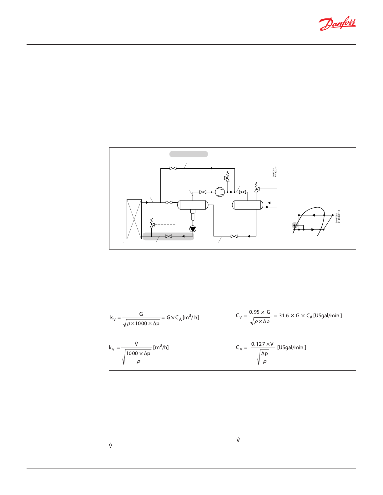
Location of valve in system (marked with grey)
Hot gas by-pass & defrost line
Dry suction line
Wet suction line
REG-SA/SB SS
This relationship between mass flow, pressure
drop and density satisfies the majority of all valve
applications with refrigerants and brines.
Normal flow is characterised by turbulent flow
through the valve without any phase change. The
following capacity curves are based on the above
mentioned assumption.
Application of the regulating valves outside
the normal flow area will reduce the capacity
of the valve considerably. In such cases it is
recommended to use "DIRcalc™" (Danfoss
Industrial Refrigeration calculation programme).
Discharge
line
Liquid line without phase change Liquid line with or without phase change
Sizing regulating valve for liquid flow
Liquid refrigerants: Use the liquid tables, fig. 6 - 10.
For other refrigerants and brines, "Normal flow"
(Turbulent flow); see below and use the flow
coefficient tables (fig. 1 - 2).
SI-units
Mass flow:
Volume flow:
kv [m3/h] Quantity [m3/h] of water flowing
Imperial units
Mass flow:
Volume flow:
Cv [US gal/min] Quantity [US gal/min] of water
through a valve at a pressure loss of
1 bar (according to VDE/VDI Norm
2173).
P1 [psi] Pressure before the valve
P1 [bar] Pressure before the valve
(upstream).
P2 [psi] Pressure after the valve
P2 [bar] Pressure after the valve
(downstream).
∆p [psi] Actual pressure loss across the
∆p [bar] Actual pressure loss across the valve
(P1–P2).
G [kg/h] Mass flow through the valve.
[m3/h] Volume flow through the valve.
G [lb/min] Mass flow through the valve.
[US gal/min] Volume flow through the valve.
ρ [lb/ft3] Density of the refrigerant before
ρ [kg/m3] Density of the refrigerant before the
valve.
CA Calculation factor (fig. 5).
CA Calculation factor (fig. 5).
flowing through a valve at a
pressure loss of 1 psi.
(upstream).
(downstream).
valve (P1–P2).
the valve
© Danfoss | DCS (ms) | 2020.01
AI235186440137en-US1101 | 16
Page 17

Data sheet | Stainless Steel Valves 15 (½ in.) - 125 ( 5 in.)
B
A
0% 25% 50%75% 100%
Turn of spindle
Opening
K
v
(Cv)
0
2
4
6
8
10
12
14
16
18
20
012345678910 11 12
(23.20)
(20.88)
(18.56)
(16.24)
(13.92)
(11.60)
(9.28)
(6.96)
(4.64)
(2.32)
B
A
0
0
0% 25% 50%75% 100%
Turn of spindle
Opening
K
v
(Cv)
0.5
1
1.5
2
2.5
3
3.5
4
4.5
5
123456789
(5.80)
(5.22)
(4.64)
(4.06)
(3.48)
(2.90)
(2.32)
(1.74)
(1.16)
(0.58)
Computation and selection
Flow coefficient
REG-SA SS 15 – 20 and REG-SB SS 15 – 20
Fig. 1
Flow coefficient
Fig. 2
© Danfoss | DCS (ms) | 2020.01
REG-SA SS 25 – 40 and REG-SB SS 25 – 40
AI235186440137en-US1101 | 17
Page 18

Data sheet | Stainless Steel Valves 15 (½ in.) - 125 ( 5 in.)
kg/h
kg/h
Computation and selection
(Continued)
Liquid R 717, density: 670 kg/m3 [42 lb/ft3]
(lb/min)
REG-SA SS 15 – 20 and REG-SB SS 15 – 20
8000
(294)
4000
(147)
0
1
2
3
4
5
6
7
8
9
Turn of spindle
A
Turn of spindle
B
∆P = 2 bar (29 psi)
∆P = 1.5 bar (22 psi)
∆P = 1 bar (14 psi)
∆P = 0.5 bar (7 psi)
0%
25%
50%
75%
100%
Opening
Fig. 3
(lb/min)
30000
(1103)
20000
(735)
10000
(368)
0
1
2
3
4
5
6
7
8
9
10
11
12
Turn of spindle
REG-SA SS 25 – 40 and REG-SB SS 25 – 40
A
∆P = 2 bar (29 psi)
∆P = 1.5 bar (22 psi)
∆P = 1 bar (14 psi)
∆P = 0.5 bar (7 psi)
0%
25%
50%
75%
100%
B
Opening
Fig. 4
© Danfoss | DCS (ms) | 2020.01
AI235186440137en-US1101 | 18
Page 19

Data sheet | Stainless Steel Valves 15 (½ in.) - 125 ( 5 in.)
Computation and selection
(Continued)
For choice of valve size and
connection see "Connections".
Calculation factor CA
Fig. 5
© Danfoss | DCS (ms) | 2020.01
AI235186440137en-US1101 | 19
Page 20

Data sheet | Stainless Steel Valves 15 (½ in.) - 125 ( 5 in.)
kg/h
Computation and selection
Example 1.
Refrigerant: R 717
Refrigerant flow: 2200 kg/h
Pressure drop:∆p = 0.5 bar
The above mentioned example is illustrated on
the following flow rate diagram and shows that
REG-SB SS 15 and 20 with cone B can be used. The
main rule is that nominal regulation range should
be below 85% opening degree. If the arrowline is
crossing 2 cone curves, the smaller cone should be
selected if opening degree
< 85%.
Flow rate diagram
(lb/min)
REG-SA SS 15 – 20 and REG-SB SS 15 – 20
8000
(294)
4000
(147)
2200
(81)
0
The example is only correct if the density of the
refrigerant is approx. 670 (kg/m3), and there must
be no build-up of flash gas in the valve.
∆P = 2 bar (29 psi)
∆P = 1.5 bar (22 psi)
∆P = 1 bar (14 psi)
∆P = 0.5 bar (7 psi)
1
2
3
4
5
6
7
8
9
Turn of spindle
0%
25%
50%
75%
Turn of spindle
A
B
100%
Opening
Fig. 6
© Danfoss | DCS (ms) | 2020.01
AI235186440137en-US1101 | 20
Page 21

Data sheet | Stainless Steel Valves 15 (½ in.) - 125 ( 5 in.)
0% 25% 50% 75% 100%
e
Opening
K
(Cv)
Computation and selection
Example 2.
Brine, density ρ: 1150 [kg/m3]
Brine flow G: 2,700 [kg/h]
Pressure drop ∆p: 0.5 [bar]
In this example it is not possible to use the
selection diagrams (fig. 3 and 4) as the refrigerant
in question is not included.
Calculation example:
Required kv-value
CA = 0.00132 (from fig. 18)
kv = CA × G
kv = 0.00132 × 2,700 [kg/h]
= 3.56 [m3/h]
Calculation factor C
Use the curves of the kv-values instead (fig. 1 - 2)
and calculate the required kv by means of the
formulas in the "Introduction" passage at the
beginning of this chapter. Alternatively calculate
the kv-values by means of the calculation factor CA
(fig. 7) and the flow rate diagram (in this example:
fig. 8) as per the following calculation example.
A
Density kg/m3
[lb/ft]
Fig. 7
Flow rate diagram
v
5
(5.80)
4.5
(5.22)
4
3.56 m3/h
(from
calculation
above)
REG-SB SS 15 and REG-SB SS 20
(4.64)
3.5
(4.06)
3
(3.48)
2.5
(2.90)
2
(2.32)
1.5
(1.74)
1
(1.16)
0.5
(0.58)
0
123456789
0
with cone B can be used.
B
A
Turn of spindl
Fig. 8
© Danfoss | DCS (ms) | 2020.01
AI235186440137en-US1101 | 21
Page 22

Data sheet | Stainless Steel Valves 15 (½ in.) - 125 ( 5 in.)
Danfoss
M148B0010_1
17
11
18
8
10
9
7
12
2
13
3A
4
1
21
5
Material specification
REG-SA SS and REG-SB SS 15 – 40
No. Part Material EN ISO ASTM
1 Housing
2
Bonnet, Flange Stainless steel X5CrNi18-10
3A
Bonnet, Insert Stainless steel
4 Spindle Stainless steel X8CrNiS 18-9, DIN 17440 Type 17, 683/13 AISI 303
5 Cone Steel
7 Packing washer Aluminium
8 Packing gland Stainless Steel X8CrNiS 18-9, 10088 Type 17, 683/13 AISI 303
9 O-ring Cloroprene (Neoprene)
10 Spring loaded Teflon ring PTFE
11 O-ring Cloroprene (Neoprene)
12 Bolts Stainless steel A2-70 A2-70 Type 308
13 Gasket Fiber, non asbestos
14 Bottom insert Steel
17 Seal cap Aluminium
18 Gasket f. seal cap Nylon
19 Locking nut Steel
20 Screw Steel
21 Disk spring Steel
Stainless steel GX5CrNi19-10
EN10213-4
EN10088
X8CrNiS18-9
DIN 17440
AISI 304
AISI 304
AISI 303
© Danfoss | DCS (ms) | 2020.01
AI235186440137en-US1101 | 22
Page 23

Data sheet | Stainless Steel Valves 15 (½ in.) - 125 ( 5 in.)
Dimensions and weights REG-SA SS and REG-SB SS 15 – 40 in angleway version
REG-SA SS and REG-SB SS 15 – 40
Valve size C G ∅D
REG-SA SS/SB SS 15 – 20
REG-SA SS/SB SS (½ – 3/4) mmin.
REG-SA SS/SB SS 25 – 40
REG-SA SS/SB SS (1 – 1 ½) mmin.
Specified weights are approximate values only.
182
7.17
237
9.33
45
1.77
55
2.17
REG-SA SS and REG-SB SS 10 – 65 in straightway version
REG-SA SS and REG-SB SS 15 – 40
38
1.50
50
1.97
H
60
2.36
70
2.76
Weight
1.4 kg
3.1 lb
2.4 kg
5.3 lb
© Danfoss | DCS (ms) | 2020.01
Valve size C B E G ∅D
REG-SA SS/SB SS 15 – 20
REG-SA SS/SB SS (½ – 3/4) mmin.
REG-SA SS/SB SS 25 – 40
REG-SA SS/SB SS (1 – 1 ½) mmin.
Specified weights are approximate values only.
145
5.71
200
7.87
155
6.10200.79
215
8.46261.02
120
4.72
155
6.10
H
38
1.50
50
1.97
60
2.36
70
2.76
AI235186440137en-US1101 | 23
Weight
2.0 kg
4.4 lb
3.0 kg
6.6 lb
Page 24

Data sheet | Stainless Steel Valves 15 (½ in.) - 125 ( 5 in.)
Ordering How to order
The table below is used to indentify the valve
required.
Please note that the type codes only serve to
identify the valves, some of which may not form
part of the standard product range. For further
information please contact your local Danfoss Sales
Company.
Type codes
Valve type REG SA SS
Nominal size in mm
(Valve size measured on
the connection diameter)
Connections D
Valve housing ANG Angle flow
Cone A Size:
Cone B Size:
REG-SB SS
DN 15
DN 20
DN 25
DN 32
DN 40
DN 15
DN 20
DN 25
DN 32
DN 40
Regulating Valves
Available connection types
15 DN 15 x x
20 DN 20 x x
25 DN 25 x x
32 DN 32 x x
40 DN 40 x x
Butt-weld connection
A
Butt-weld connection
STR Straight flow
Flow area [mm2]
36.5
36.5
178
178
178
Flow area [mm2]
115
115
531
531
531
D A
: DIN EN 10220
: ANSI B 36.19M
Example:
REG-SA SS (Cone B) 15 DIN
angleway = 148B5387
Important!
Where products need to be
certified according to specific
certification societies or where
higher pressures are required, the
relevant information should be
included at the time of order.
D = Butt-weld DIN
A = Butt-weld ANSI
ANG = Angleway
STR = Straightway
Complete REG-SA SS (Cone type A)
Butt-weld DIN (EN 10220)
Size Type Code no.
mm in.
Angleway - REG-SA SS with cone type A
15 ½ REG-SA SS 15 D ANG 148B5297
20 ¾ REG-SA SS 20 D ANG 148B5385
25 1 REG-SA SS 25 D ANG 148B5494
32 1 ¼ REG-SA SS 32 D ANG 148B5589
40 1 ½ REG-SA SS 40 D ANG 148B5674
Butt-weld ANSI (B 36.19M SCHEDULE 40)
Size Type Code no.
mm in.
Angleway - REG-SA SS with cone type A
15 ½ REG-SA SS 15 A40 ANG 148B6482
25 1 REG-SA SS 25 A40 ANG 148B6483
32 1 ¼ REG-SA SS 32 A40 ANG 148B6484
Butt-weld DIN (EN 10220)
Size Type Code no.
mm in.
Straightway - REG-SA SS with cone type A
15 ½ REG-SA SS 15 D STR 148B5298
20 ¾ REG-SA SS 20 D STR 148B5386
25 1 REG-SA SS 25 D STR 148B5495
32 1 ¼ REG-SA SS 32 D STR 148B5590
40 1 ½ REG-SA SS 40 D STR 148B5675
Butt-weld ANSI (B 36.19M SCHEDULE 40)
Size Type Code no.
mm in.
Straightway - REG-SA SS with cone type A
15 ½ REG-SA SS 15 A40 STR 148B5299
25 1 REG-SA SS 25 A40 STR 148B6485
32 1 ¼ REG-SA SS 32 A40 STR 148B6486
© Danfoss | DCS (ms) | 2020.01
AI235186440137en-US1101 | 24
Page 25

Data sheet | Stainless Steel Valves 15 (½ in.) - 125 ( 5 in.)
Ordering
D = Butt-weld DIN
A = Butt-weld ANSI
ANG = Angleway
STR = Straightway
Replacement kit (O-ring
replacement) for
R717 Ammonia Heat
Pump* and Propylene
applications (including
ID tag)
Complete REG-SB SS (Cone type B)
Butt-weld DIN (EN 10220)
Size Type Code no.
mm in.
Angleway - REG-SB SS with cone type B
15 ½ REG-SB SS 15 D ANG 148B5387
20 ¾ REG-SB SS 20 D ANG 148B5389
25 1 REG-SB SS 25 D ANG 148B5496
32 1 ¼ REG-SB SS 32 D ANG 148B5591
40 1 ½ REG-SB SS 40 D ANG 148B5676
Butt-weld ANSI (B 36.19M SCHEDULE 40)
Size Type Code no.
mm in.
Angleway - REG-SB SS with cone type B
20 ¾ REG-SB SS 20 A40 ANG 148B6487
40 1 ½ REG-SB SS 40 A40 ANG 148B5686
Size O-ring kit for
mm in.
10 /₈ 148B6084 148B6085
15 ½
20 ¾
25 1
40 1½
* Replacement kits for R717 Ammonia Heat Pump is
applicable for continuous operating temperature between
+100°C to 150°C (212°F to 302°F)
R717
Heat pump
148B6070 148B6077
148B6071 148B607832 1¼
R1270
Propylene
Butt-weld DIN (EN 10220)
Size Type Code no.
mm in.
Straightway - REG-SB SS with cone type B
15 ½ REG-SB SS 15 D STR 148B5388
20 ¾ REG-SB SS 20 D STR 148B5390
25 1 REG-SB SS 25 D STR 148B5497
32 1 ¼ REG-SB SS 32 D STR 148B5592
40 1 ½ REG-SB SS 40 D STR 148B5677
Butt-weld ANSI (B 36.19M SCHEDULE 40)
Size Type Code no.
mm in.
Straightway - REG-SB SS with cone type B
20 ¾ REG-SB SS 20 A40 STR 148B6488
25 1 REG-SB SS 25 A40 STR 148B6479
40 1 ½ REG-SB SS 40 A40 STR 148B5685
© Danfoss | DCS (ms) | 2020.01
AI235186440137en-US1101 | 25
Page 26
Data sheet | Stainless Steel Valves 15 (½ in.) - 125 ( 5 in.)
Pressure
Temperature
˚C
psi
bar
Check & stop valves and
check valves
SCA-X SS and CHV-X SS
Features
SCA-X SS and CHV-X SS
In certain specific areas such as outdoor
applications and corrosive atmospheres, such as
coastal installations, there is a need for high surface
protection to prevent failure due to corrosion.
Today's food safety standards often call for daily
treatment with detergents to protect against
bacteria growth, again producing a need for high
surface protection.
SCA-X SS are check valves with a built-in stop valve
function. CHV-X SS are check valves only.
The valves are designed to open at very low
differential pressures, allow favourable flow
conditions and are easy to disassemble for
inspection and service.
The valve cone has a built-in flexibility to ensure a
precise and tight closing towards the valve seat.
A well balanced dampening effect between the
piston and the cylinder gives an optimal protection
during low loads and against pulsations.
• Applicable to HCFC, HFC, R717 (Ammonia), R744
(CO2), Propane, Butane, Iso-Butane and Ethane.
R717 Heat Pump and Propylene applications
with replaced O-ring.
• Designed to give favourable flow conditions.
• Internal backseating enables replacement
of the spindle seal whilst the valve is active, i.e.
under pressure (SCA-SS)
• Housing is made of special cold resistant
stainless steel approved for low temperature
operations.
• Easy to disassemble for inspection and service.
• Butt-weld DIN and ANSI connections.
• Max. operating pressure:
52 bar g / 754 psig
• Tem perature range:
-60 – 150 °C / -76 – 302 °F.
• Compact and light valves for easy handling and
installation.
• Classification: DNV, CRN, BV, EAC etc.
To get an updated list of certification on the
products please contact your local Danfoss Sales
Company.
Pressure and
temperature range
Technical data • Refrigerants
798
55
725
50
653
45
580
40
508
35
435
30
363
25
Pressure
290
20
218
15
145
10
73
5
0
0
-70
-50-30 -101030507090 110 130 150
-94-58 -22145086 122 158 194 230 266 302
Temperature
Applicable to HCFC, HFC, R717 (Ammonia), R744
(CO2), Propane, Butane, Iso-Butane and Ethane.
R717 Heat Pump and Propylene applications
˚F
• Temperature range
• Max. working pressure
with replaced O-ring.
SCA-X SS/CHV-X SS DN15-DN40
-60 – 150 °C / -76 – 302 °F.
52 bar g / 754 psig.
For further information refer to the product
instruction for SCA-X SS/CHV-X SS.
© Danfoss | DCS (ms) | 2020.01
AI235186440137en-US1101 | 26
Page 27
Data sheet | Stainless Steel Valves 15 (½ in.) - 125 ( 5 in.)
S
S
Design Connections
Available with the following connections:
• Butt-weld DIN (EN 10220)
DN 15 – 40 (½ – 1 ½ in.)
• Butt-weld ANSI (B 36.19M)
DN 20 – 40 (¾ – 1 ½ in.)
Housing
Made of stainless steel approved for low
temperature operations.
Valve cone
Valve cone with built in metallic stop - prevents
damage to teflon ring in case of overtightening.
Damping chamber
The chamber is filled with refrigerants (gas or
liquid), which provides a damping effect when the
valve opens and closes.
Spindle (SCA-X SS)
Made of polished stainless steel, which is ideal for
O-ring sealing.
Packing Gland (SCA-X SS)
The “full temperature range” packing gland is the
standard for the entire SVL platform.
This ensures perfect tightness throughout the
whole temperature range:
-60 – 150 °C / -76 – 302 °F.
Pressure Equipment Directive (PED)
The SCA-X SS/CHV-X SS valves are approved
according to the European standard specified
in the Pressure Equipment Directive and are CE
marked.
For further details / restrictions - see the product
instruction.
Installation
The valve must be mounted vertically with the
cone downwards.
The valve is designed to resist very high internal
pressure. However, the piping system in general
should be designed to avoid liquid traps and
reduce the risk of hydraulic pressure caused by
thermal expansion.
For further information refer to installation
instructions for SCA-X SS/CHV-X SS.
If cold refrigeration oil having low viscosity enters
and settles in the damping chamber, problems
with the check valve may arise. Consequently, it
may be necessary to modify the valve for more
viscous liquids by enlarging the hole to the
damping chamber.
”
½
/
5
1
N
D
X
-
V
H
C
E
V
L
A
V
K
C
E
H
C
Example of marking ring, CHV-X SS
Connections
DIN
ANSI
SCA-X SS/CHV-X SS valves
Nominal bore
Classified for Fluid group I
Category Article 3, paragraph 3 II
Size OD T
Butt-weld DIN (EN 10220)
15 mm 21.3 2.3
½ in. 0.839 0.091
20 mm 26.9 2.3
¾ in 1.059 0.091
25 mm 33.7 2.6
1 in. 1.327 0.103
32 mm 42.4 2.6
1 ¼ in. 1.669 0.102
40 mm 48.3 2.6
1 ½ in. 1.902 0.103
DN = < 25 mm (1 in.) DN32-40 mm (1 ¼ – 1 ½ in.)
Size OD T
Butt-weld ANSI B 36.19M, SCHEDULE 40
20 mm 26.9 2.9
¾ in 1.06 0.11
25 mm 33.7 3.5
1 in. 1.33 0.14
32 mm 42.4 3.6
1 ¼ in. 1.67 0.14
40 mm 48.3 3.7
1 ½ in. 1.9 0.15
© Danfoss | DCS (ms) | 2020.01
AI235186440137en-US1101 | 27
Page 28
Data sheet | Stainless Steel Valves 15 (½ in.) - 125 ( 5 in.)
Danfoss
M148G0009_1
1
2
3
5
14
13
12
6
15
17
8
9
4
3
12
13
7
14
5
1
16
15
2
6
11
10
Danfoss
M148G0008_1
Material specification
12
2
3
13
14
5
6
1
SCA-X SS 15 - 40
No. Part Material DIN/EN ISO ASTM
1 Housing
2 Bonnet, Flange
3 Bonnet, Insert Stainless steel
4 Spindle
5 Cone Steel
6
O-ring Cloroprene (Neoprene)
7 Spindle extension Steel
8 Packing gland
O-rings
9 Packing washer Aluminium
10 Spring loaded seal Teflon (PTFE)
11 O-ring Cloroprene (Neoprene)
12 Bolts Stainless steel A2-70 A2-70 Type 308
13 Gasket Fiber, non-asbestos
14 Spring Steel
15 Identification ring Stainless steel
16 Seal cap gasket Nylon
17 Spindle seal cap Aluminium
Stainless steel GX5CrNi19-10
Stainless steel X5CrNi18-10
Stainless steel X8CrNiS18-9
Teflon (PTFE)
Stainless steel
Cloroprene (Neoprene)
CHV-X SS 15 - 40
CHV-X SS 15 - 40
AISI 304
EN10213-4
AISI 304
EN10088
X8CrNiS18-9
DIN 17440
Type 17, 17440 AISI 303
DIN 17440
15
Danfoss
148G237_02-2017
© Danfoss | DCS (ms) | 2020.01
AI235186440137en-US1101 | 28
Page 29
Data sheet | Stainless Steel Valves 15 (½ in.) - 125 ( 5 in.)
DA
148G238_02-201
Dimensions and weights
SCA-X SS/CHV-X SS 15 – 40 (½ – 1 ½ in.)
SCA-X SS 15 - 40
CHV-X SS 15 - 40
G
B
C
E
H
7
NFOSS
Specified weights are approximate
values only.
Valve size C G ∅D F
SCA-X SS 15 – 40
SCA-X SS 15 (½ in.)
SCA-X SS 20 (¾ in.)
SCA-X SS 25 (1 in.)
SCA-X SS 32 (1 ¼ in.)
SCA-X SS 40 (1 ½ in.)
mm 212 45 38 60 60
in. 8.35 1.77 1.50 2.36 2.36
mm 212 45 38 60 60
in. 8.35 1.77 1.50 2.36 2.36
mm 295 55 50 85 70
in. 11.61 2.17 1.97 3.35 2.76
mm 295 55 50 85 70
in. 11.61 2.17 1.97 3.35 2.76
mm 295 55 50 85 70
in. 11.61 2.17 1.97 3.35 2.76
CHV-X SS 15 – 40 Angleway
CHV-X SS 15 (½ in.)
CHV-X SS 20 (¾ in.)
CHV-X SS 25 (1 in.)
CHV-X SS 32 (1 ¼ in.)
CHV-X SS 40 (1 ½ in.)
Valve size C B E G F
mm 103
in.
mm 103 45 60 60
in. 4.06 1.77 2.36 2.36
mm 143 55 85 70
in. 5.63 2.17 3.35 2.76
mm 143 55 85 70
in. 5.63 2.17 3.35 2.76
mm 143 55 85 70
in. 5.63 2.17 3.35 2.76
4.06
45
1.77
CHV-X SS 15 – 40 Straightway
CHV-X SS 15 (½ in.)
CHV-X SS 20 (¾ in.)
CHV-X SS 25 (1 in.)
CHV-X SS 32 (1 ¼ in.)
CHV-X SS 40 (1 ½ in.)
mm 99 114 19 120 60 60 1.3kg
in. 3.90 4.49 0.75 4.72 2.36 2.36 2.87lb
mm 99 114 19 120 60 60 1.3kg
in. 3.90 4.49 0.75 4.72 2.36 2.36 2.87lb
mm 141 157 26 155 85 70 2.6kg
in. 5.55 6.18 1.02 6.10 3.35 2.76 5.73lb
mm 141 157 26 155 85 70 2.6kg
in. 5.55 6.18 1.02 6.10 3.35 2.76 5.73lb
mm 141 157 26 155 85 70 2.6kg
in. 5.55 6.18 1.02 6.10 3.35 2.76 5.73lb
60
2.36
min
2.36
min
H
60
H
Weight
1.6 kg
3.53 lb
1.6 kg
3.53 lb
3.2 kg
7.05 lb
3.2 kg
7.05 lb
3.2 kg
7.05 lb
1.2 kg
2.65 lb
1.2 kg
2.65 lb
2.3 kg
5.07 lb
2.3 kg
5.07 lb
2.3 kg
5.07 lb
Weight
© Danfoss | DCS (ms) | 2020.01
AI235186440137en-US1101 | 29
Page 30
Data sheet | Stainless Steel Valves 15 (½ in.) - 125 ( 5 in.)
Ordering
How to order
The table below is used to identify the valve
required.
Please note that the type codes only serve to identify the valves, some of wich may not form part of
the standard product range.
Valve type SCA-X SS
CHV-X SS
(valve size measured on the
connection diameter)
Connections D
Valve housing ANG Angle flow
Stop Check Valve
Check Valve
15 DN 15 x
20 DN 20 x x
25 DN 25 x x
32 DN 32 x x
40 DN 40 x x
Butt-weld connection
A
Butt-weld connection
STR Straight flow
Important!
Where products need to be certified according
to specific certification societies the relevant
information should be included at the time of
order.
SCA-X SS Angleway
Butt-weld DIN (EN 10220)
Size
mm in.
15 ½ SCA-X SS 15 D ANG 148B5293
20 ¾ SCA-X SS 20 D ANG 148B5381
25 1 SCA-X SS 25 D ANG 148B5490
32 1 ¼ SCA-X SS 32 D ANG 148B5585
40 1 ½ SCA-X SS 40 D ANG 148B5664
Butt-weld ANSI (B 36.19M SCHEDULE 40)
Size
mm in.
20 ¾ SCA-X SS 20 A40 ANG 148B6489
25 1 SCA-X SS 25 A40 ANG 148B6480
32 1 ¼ SCA-X SS 32 A40 ANG 148B6490
40 1 ½ SCA-X SS 40 A40 ANG 148B5687
Type Code No.
Type Code No.
For further information please contact your local
Danfoss Sales Company.
D A
: DIN EN 10220
: ANSI B 36.19M
ANG = Angleway
STR = Straightway
Replacement kit (O-ring
replacement) for
R717 Ammonia Heat
Pump* and Propylene
applications (including
ID tag)
© Danfoss | DCS (ms) | 2020.01
CHV-X SS Angleway
Butt-weld DIN (EN 10220)
Size
mm in.
15 ½ CHV-X SS 15 D ANG 148B5294
20 ¾ CHV-X SS 20 D ANG 148B5382
25 1 CHV-X SS 25 D ANG 148B5491
32 1 ¼ CHV-X SS 32 D ANG 148B5586
40 1 ½ CHV-X SS 40 D ANG 148B5665
Butt-weld ANSI (B 36.19M SCHEDULE 40)
Size
mm in.
20 ¾ CHV-X SS 20 A40 ANG 148B6491
25 1 CHV-X SS 25 A40 ANG 148B6481
32 1 ¼ CHV-X SS 32 A40 ANG 148B6492
40 1 ½ CHV-X SS 40 A40 ANG 148B5688
Size O-r ing kit for
mm in.
15 ½
20 ¾
25 1
40 1½
Type Code No.
Type Code No.
R717
Heat pump
148B6070 148B6077
148B6071 148B607832 1¼
R1270
Propylene
CHV-X SS Straightway
Butt-weld DIN (EN 10220)
Size
mm in.
15 ½ CHV-X SS 15 D STR 148B5678
20 ¾ CHV-X SS 20 D STR 148B5679
25 1 CHV-X SS 25 D STR 148B5680
32 1 ¼ CHV-X SS 32 D STR 148B6544
40 1 ½ CHV-X SS 40 D STR 148B6566
Type Code No.
Butt-weld ANSI (B 36.19M SCHEDULE 40)
Size
mm in.
20 ¾ CHV-X SS 20 A40 STR 148B6608
25 1 CHV-X SS 25 A40 STR 148B6609
32 1 ¼ CHV-X SS 32 A40 STR 148B6610
40 1 ½ CHV-X SS 40 A40 STR 148B6611
Type Code No.
* Replacement kits for R717 Ammonia Heat Pump is
applicable for continuous operating temperature between
+100°C to 150°C (212°F to 302°F)
AI235186440137en-US1101 | 30
Page 31
Data sheet | Stainless Steel Valves 15 (½ in.) - 125 ( 5 in.)
Pressure
Temperature
˚C
psi
bar
Strainers
FIA SS
Features
FIA SS
In certain specific areas such as outdoor
applications and corrosive atmospheres, such as
coastal installations, there is a need for high surface
protection to prevent failure due to corrosion.
Today's food safety standards often call for daily
treatment with detergents to protect against
bacteria growth, again producing a need for high
surface protection.
FIA SS strainers are a range of angle-way and
straight-way strainers which are carefully
designed to give favourable flow conditions.
The design makes the strainer easy to install, and
ensures quick strainer inspection and cleaning.
FIA SS strainers are used ahead of automatic
controls, pumps, compressors etc., for
initial plant start-up and where permanent
filtration of the refrigerant is required. The
strainer reduces the risk of undesirable system
breakdowns and reduces wear and tear on
plant components.
• Applicable to HCFC, HFC, R717 (Ammonia), R744
(CO2) and all flammable refrigerants.
• Designed to give favourable flow conditions.
• Housing is made of special cold resistant
stainless steel approved for low temperature
operations.
• Easy to disassemble for inspection and service.
• Butt-weld DIN and ANSI connections.
• Max. operating pressure:
52 bar g / 754 psig
• Tem perature range:
-60 – 150 °C / -76 – 302 °F.
• Compact and light valves for easy handling and
installation.
• Classification: DNV, CRN, BV, EAC etc.
To get an updated list of certification on the
products please contact your local Danfoss Sales
Company.
Pressure and
temperature range
Technical data • Refrigerants
798
55
725
50
653
45
580
40
508
35
435
30
363
25
Pressure
290
20
218
15
145
10
73
5
0
0
-70
-50-30 -101030507090 110 130 150
-94-58 -22145086 122 158 194 230 266 302
˚F
• Temperature range
Applicable to HCFC, HFC, R717 (Ammonia), R744
(CO2) and all flammable refrigerants.
For further information please see installation
• Max. working pressure:
guide for FIA SS.
© Danfoss | DCS (ms) | 2020.01
FIA SS DN15-DN65
-60 – 150 °C / -76 – 302 °F.
52 bar g / 754 psi g.
AI235186440137en-US1101 | 31
Page 32

Data sheet | Stainless Steel Valves 15 (½ in.) - 125 ( 5 in.)
S
S
D
Design
Connections
Available with the following connections:
• Butt-weld DIN (EN 10220)
DN 15 – 65 (½ – 2 ½ in.)
• Butt-weld ANSI (B 36.19M)
DN 15 – 65 (½ – 2 ½ in.)
Strainer Insert
A filter grid and filter net of stainless steel ensure
long element life. The filter net offers a very high
degree of cleanability.
Housing
Made of stainless steel approved for low
temperature operations.
Pressure Equipment Directive (PED)
FIA SS strainers are approved in accordance with
the European standard specified in the Pressure
Equipment Directive and are CE marked.
For further details / restrictions - see Installation
Instruction.
Installation / Maintenance
The strainer is designed to resist high internal
pressures. However, the piping system in general
should be designed to avoid liquid traps and
reduce the risk of hydraulic pressure caused by
thermal expansion.
Danfoss recommends replacement/cleaning of
the strainer when the differential pressure loss
>0.5 bar / 7.3 psi in the liquid line and >0.05 bar /
0.7 psi in the suction line. The max. permissible
differential pressure is 1 bar / 15 psi.
For further information refer to installation
instruction for FIA SS.
Identification:
”
½
/
5
1
N
A
I
F
R
E
T
L
I
F
Example of marking ring, FIA SS
Connections
DIN
ANSI
Install the strainer with the cover in downward
position.
FIA SS
Nominal bore DN ≤25 (1 in.) DN 32 – 65 mm (11/4 – 2 ½ in.)
Classified for Fluid group I
Category Article 3, paragraph 3 II
Size OD T
Butt-weld DIN (EN 10220)
15 mm 21.3 2.3
½ in. 0.839 0.091
20 mm 26.9 2.3
¾ in 1.059 0.091
25 mm 33.7 2.6
1 in. 1.327 0.103
32 mm 42.4 2.6
1 ¼ in. 1.669 0.102
40 mm 48.3 2.6
1 ½ in. 1.902 0.103
50 mm 60.3 2.9
2 in. 2.37 0.11
65 mm 76.1 2.9
2 ½ in. 3 0.11
Size OD T
Butt-weld ANSI (B 36.19M)
15 mm 21.3 2.8
½ in. 0.839 0.11
20 mm 26.9 2.9
¾ in 1.06 0.11
25 mm 33.7 3.5
1 in. 1.33 0.14
32 mm 42.4 3.6
1 ¼ in. 1.67 0.14
40 mm 48.3 3.7
1 ½ in. 1.9 0.15
50 mm 60.3 2.8
2 in. 2.37 0.11
65 mm 73 3.1
2 ½ in. 2.87 0.12
© Danfoss | DCS (ms) | 2020.01
AI235186440137en-US1101 | 32
Page 33

Data sheet | Stainless Steel Valves 15 (½ in.) - 125 ( 5 in.)
Selection of strainer size
Definition
Mesh is the number of threads per inch.
µ (microns) is the distance between two
threads (1µ = 1 /1000 mm).
The mesh aperture size of the strainer must
satisfy the requirements stated by the sup pliers
The following recommendations of aperture size
apply in general to refrigeration installations:
of the equipment to be protected.
All lines
First start up:.............................................................................................................. 50µ
(Use filter element with removable insert for FIA SS DN15-40 or
separate filter bag for FIA SS DN 50-65. 50µ insert should normally
be removed after the first 24 hours of operation)
Liquid Lines
Ahead of pumps: ..................................................................................................... 500µ [38 mesh]
After pumps: ............................................................................................................. 150µ [100 mesh] / 250µ [72 mesh]
In front of AKVA valves .......................................................................................... 100µ [150 mesh]
Protection of automatic regulation equipment
Generally ................................................................................................................... 150µ [100 mesh] / 250µ [72 mesh]
Sensitive equipment, e.g.
suction regulators with low temperature ...................................................... 250µ [72 mesh]
Suction Lines
Ahead of screw compressor ............................................................................... 250µ [72 mesh]
Ahead of piston compressor .............................................................................. 150µ [100 mesh]
Flow coefficient (DIN / ANSI)
Connection size (DN)
FIA SS
15 - 20
(1/2” – 3/4”)
25 - 40
(1” – 1 1/2”)
50 (2”)
65 (2 1/2”)
µ
mesh wire
mm
100 0.068 0.003 35 25 3.9 45 7.0
150 100 0.10 0.004 36 25 3.9 45 7.0
250 72 0.10 0.004 51 25 3.9 45 7.0
500 38 0.16 0.006 57.6 25 3.9 45 7.0
100 0.068 0.003 35 71 11 160 25.0
150 100 0.10 0.004 36 71 11 160 25.0
250 72 0.10 0.004 51 71 11 160 25.0
500 38 0.16 0.006 57.6 71 11 160 25.0
100 0.068 0.003 35 71 11 200 31.2
150 100 0.10 0.004 36 87 13.5 200 31.2
250 72 0.10 0.004 51 87 13.5 200 31.2
500 38 0.16 0.006 57.6 87 13.5 200 31.2
150 100 0.10 0.004 36 127 19.7 305 47.6
250 72 0.10 0.004 51 127 19.7 305 47.6
500 38 0.16 0.006 57.6 127 19.7 305 47.6
wire
in.
free
space
%
Plain elements Pleated elements
2
cm
screen area
2
in
cm
2
2
in
© Danfoss | DCS (ms) | 2020.01
Kv values
DN FIA SS angle - plain filter net FIA SS angle - pleated filter net
µ100 µ150 µ250 µ500 µ150 µ250 µ500
15 3.3 3.4 3.5 3.7 4.2
20 6.9 7.1 7.3 7.7 8.8
25 13.8 14.0 14.5 15.2 17.2 17.9
32 23.0 23.8 24.7 25.5 29.2 30.5
40 25.1 25.5 26.4 28.1 31.4 32.6
50 45.1 45.9 47.6 50.2 56.7 58.8 62.0
65 56.1 57.8 60.4 69.3 71.4 74.6
DN FIA SS straight - plain filter net FIA SS straight - pleated filter net
µ100 µ150 µ250 µ500 µ150 µ250 µ500
15 2.5 2.6 2.7 2.8 3.3
20 5.3 5.4 5.6 5.9 6.9
25 10.5 10.7 11.1 11.6 13.8 14.5
32 17.6 18.2 18.9 19.5 23.9 24.7
40 19.2 19.5 20.2 21.5 25.5 26.4
50 34.5 35.1 36.4 38.4 45.9 47.6 50.2
65 42.9 44.2 46.2 56.1 57.8 60.4
AI235186440137en-US1101 | 33
Page 34

Data sheet | Stainless Steel Valves 15 (½ in.) - 125 ( 5 in.)
Material specification
FIA SS 15 - 40 (½ in. - 1½ in.)
1
1
2
6
2
3
4
FIA SS 15 - 40 (½ in. - 1½ in.)
No. Part Material DIN ISO ASTM
1 Housing Stainless steel (FIA SS only) GX5CrNi19-10
2 Gasket Fibre, Non-asbestos
3 Cover Stainless steel (FIA SS only) GX5CrNi19-10
4 Bolts Stainless steel A2-70 A2-70 Type 308
5 Marking label Aluminium
6 Filter element Stainless steel
7 Pressure relief (screw) NPT ¼” Stainless steel
FIA SS 50 - 65 (2 in. - 2½ in.)
5
7
EN10213-4
EN10213-4
3
5
7
4 6
AISI 304
AISI 304
1
2
3
1
2
3
4
FIA SS 50 - 65 (2 in. - 2½ in.)
No. Part Material DIN ISO ASTM
1 Housing Stainless steel (FIA SS only) GX5CrNi19-10
2 Gasket Fibre, Non-asbestos
3 Cover Stainless steel (FIA SS only) GX5CrNi19-10
4 Bolts Stainless steel A2-70 A2-70 Type 308
5 Marking label Aluminium
6 Filter element Stainless steel
7 Pressure relief (screw) G ½” Stainless steel
8 Packing washer Aluminium
© Danfoss | DCS (ms) | 2020.01
6
8
5
7
EN10213-4
EN10213-4
4
7
8
5
6
AISI 304
AISI 304
AI235186440137en-US1101 | 34
Page 35

Data sheet | Stainless Steel Valves 15 (½ in.) - 125 ( 5 in.)
FIA SS 15 – 65 Dimensions and weights
StraightwayAngleway
© Danfoss | DCS (ms) | 2020.01
Angleway
Strainer size A C H F
FIA SS 15 – 20 mm 45 105 60 68 1.1 kg
(1/2" – 3/4") in. 1.77 4.13 2.36 2.68 2.4 lbs
FIA SS 25-40 mm 55 132 70 95 1.7 kg
(1" – 1 1/2") in. 2.17 5.20 2.76 3.74 3.7 lbs
FIA SS 50 mm 60 132 77 92 2.8 kg
(2") in. 2.36 5.20 3.03 3.62 6.2 lbs
FIA SS 65 mm 70 152 90 107 3.8 kg
(2 1/2") in. 2.76 5.98 3.54 4.21 8.4 lbs
min.
Weight
Straightway
Valve size A C C
FIA SS 15 – 20 mm 120 99 133 60 20 68 1.4 kg
(1/2" – 3/4") in. 4.72 3.90 5.24 2.36 0.79 2.68 3.1 lbs
FIA SS 25 – 40 mm 155 129 177 70 26 95 2.4 kg
(1" – 1 1/2") in. 6.10 5.08 6.97 2.76 1.02 3.74 5.3 lbs
FIA SS 50 mm 148 138 184 77 32 92 3.5 kg
(2") in. 5.83 5.43 7.24 3.03 1.26 3.62 7.7 lbs
FIA SS 65 mm 176 165 219 90 40 107 5.3 kg
(2 1/2") in. 6.93 6.50 8.62 3.54 1.57 4.21 11.7 lbs
min.
H E F
min.
Weight
AI235186440137en-US1101 | 35
Page 36

Data sheet | Stainless Steel Valves 15 (½ in.) - 125 ( 5 in.)
Ordering
The table below is used to identify the strainer
required. Please note that you have to order
FIA SS strainer without element, a strainer
element and accessories.
Size Type FIA SS
Without
Filter
Element
Filter
Element
100µ
150 mesh
Filter
Element
150µ
100 mesh
Example:
FIA SS 50 D ANG + FIA-X 50 150µStrainer
Element + Filter Bag = 148H5757 + 148H3130 +
148H3150
Filter
Element
250µ
72 mesh
Filter
Element
500µ
38 mesh
Pleated filter
element
150µ
100 mesh
Pleated filter
element
250µ
72 mesh
Pleated filter
element
500µ
38 meshmm in.
Butt-weld DIN (EN 10220) - Angleway
15 ½ FIA SS 15 D ANG 148B5295
20 ¾ FIA SS 20 D ANG 148B5383
25 1 FIA SS 25 D ANG 148B5492
40 1 ½ FIA SS 40 D ANG 148B5666
50 2 FIA SS 50 D ANG 148B5757 148H3157 148H3130 148H3138 148H3144 148H3179 148H3184 148H3189
65 2 ½ FIA SS 65 D ANG 148B5851 – 148H3131 148H3139 148H3145 148H3180 148H3185 148H3190
148H3122 148H3124 148H3126 148H3128 148H3303 148H3363 –
148H3123 148H3125 148H3127 148H3129 148H3304 148H3269 – 32 1 ¼ FIA SS 32 D ANG 148B5587
Butt-weld ANSI (B 36.19M SCHEDULE 10) - Angleway
65 2½ FIA SS 65 A10 ANG 148B6498 – 148H3131 148H3139 148H3145 148H3180 148H3185 148H3190
Butt-weld DIN (EN 10220) - Straightway
15 ½ FIA SS 15 D STR 148B5296
20 ¾ FIA SS 20 D STR 148B5384
25 1 FIA SS 25 D STR 148B5493
40 1 ½ FIA SS 40 D STR 148B5667
50 2 FIA SS 50 D STR 148B5758 148H3157 148H3130 148H3138 148H3144 148H3179 148H3184 148H3189
65 2 ½ FIA SS 65 D STR 148B5852 – 148H3131 148H3139 148H3145 148H3180 148H3185 148H3190
148H3122 148H3124 148H3126 148H3128 148H3303 148H3363 –
148H3123 148H3125 148H3127 148H3129 148H3304 148H3269 – 32 1 ¼ FIA SS 32 D STR 148B5588
Butt-weld ANSI (B 36.19M SCHEDULE 40) - Straightway
15 ½ FIA SS 15 A40 STR 148B6493
20 ¾ FIA SS 20 A40 STR 148B6494
25 1 FIA SS 25 A40 STR 148B6495
40 1 ½ FIA SS 40 A40 STR 148B6497
148H3122 148H3124 148H3126 148H3128 148H3303 148H3363 –
148H3123 148H3125 148H3127 148H3129 148H3304 148H3269 – 32 1 ¼ FIA SS 32 A40 STR 148B6496
Butt-weld ANSI (B 36.19M SCHEDULE 10) - Straightway
50 2 FIA SS 50 A10 STR 148B5758 148H3157 148H3130 148H3138 148H3144 148H3179 148H3184 148H3189
65 2 ½ FIA SS 65 A10 STR 148B6499 – 148H3131 148H3139 148H3145 148H3180 148H3185 148H3190
D = Butt-weld DIN
A = Butt-weld ANSI
ANG = Angleway
STR = Straightway
Accessories
Part Accessory for Code number
Filter element µ150 with removable
element µ50 for the first start up
Part Accessory for Code number
Filter bag
Part Accessory for Code number
Blind nut with gasket FIA SS 50 – 65 148H3450
FIA SS 15 – 20 148H3301
FIA SS 25 – 40 148H3302
FIA SS 50 148H3150
FIA SS 65 148H3151
© Danfoss | DCS (ms) | 2020.01
AI235186440137en-US1101 | 36
Page 37
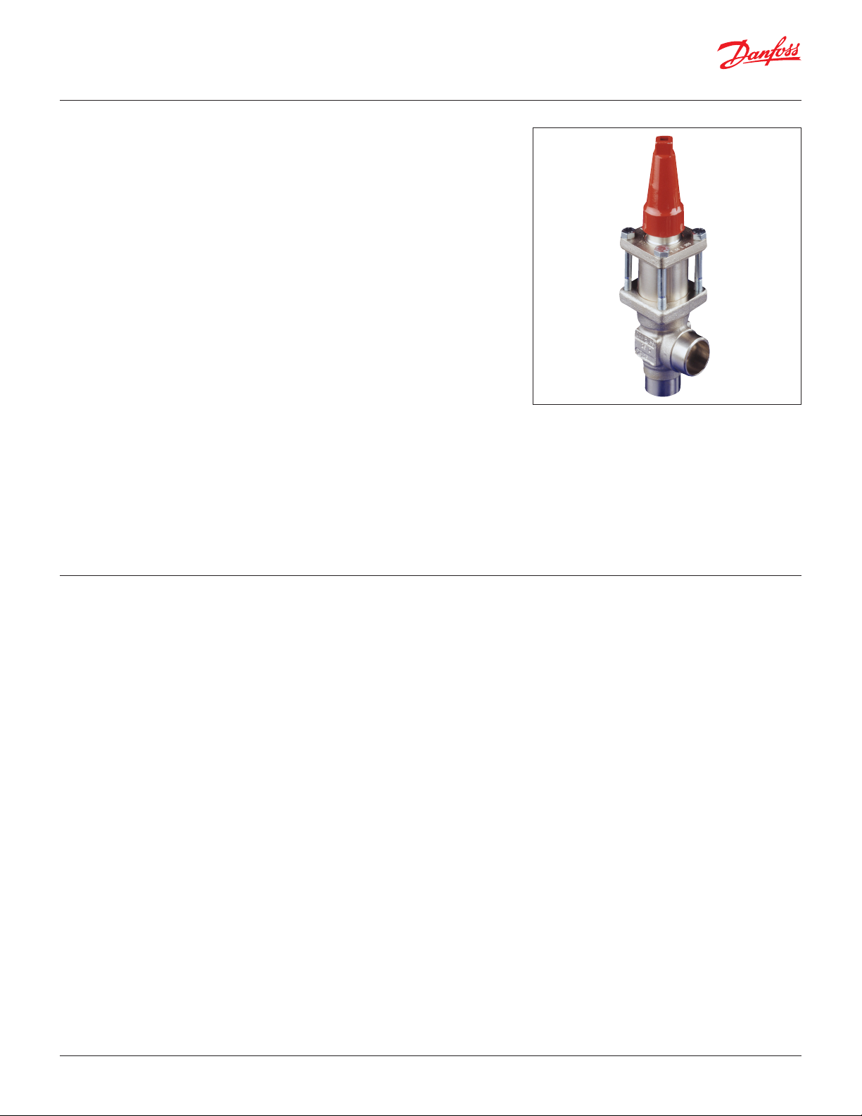
Data sheet | Stainless Steel Valves 15 (½ in.) - 125 ( 5 in.)
Pressure regulating valves
OFV-SS
Features
OFV-SS
OFV-SS are angle-way over flow valves, which
have ajustable opening pressure and cover
the differential pressure range (∆P): 2 – 8 bar /
29 – 116 psi. The valve can be closed manually,
e.g. during plant service and have backseating,
enabling the spindle seal to be replaced with the
valve still under pressure.
The valves are especially designed to prevent
fluttering due to low velocity and/or low density.
In consequence it is possible to apply the valves
with wide fluctuations in capacity demands,
i.e. from maximum performance to part load. A
flexible O-ring provides perfect sealing over the
seat.
• Applicable to HCFC, HFC, R717(Ammonia)
and R744 (CO2).
• Full temperature range packing gland
-50 – 150 °C / -58 – 302 °F
• Maximum operating pressure
52 bar / 754 psi g
• Three functions in one valve. The OFV valve
combines the functions of an overflow valve, a
check valve and a stop valve
• Low temperature stainless steel housing and
bonnet
• Low temperature packing gland
-60 – 150 °C / -76 – 302 °F
• Classification: DNV, CRN, BV, EAC etc.
To get an updated list of certification on the
products please contact your local Danfoss Sales
Company.
Technical data • Refrigerants
Applicable to HCFC, HFC, R717(Ammonia)
and R744 (CO2).
Flammable hydrocaarbons are not
recommended. For further information please
contact your local Danfoss Sales Company.
• Temperature range
-60 – 150 °C / -76 – 302 °F
• Pressure range
Maximum operating pressure:
52 bar / 754 psi g
• Set pressure (∆p): 2 – 8 bar / 29 – 116 psi.
© Danfoss | DCS (ms) | 2020.01
AI235186440137en-US1101 | 37
Page 38
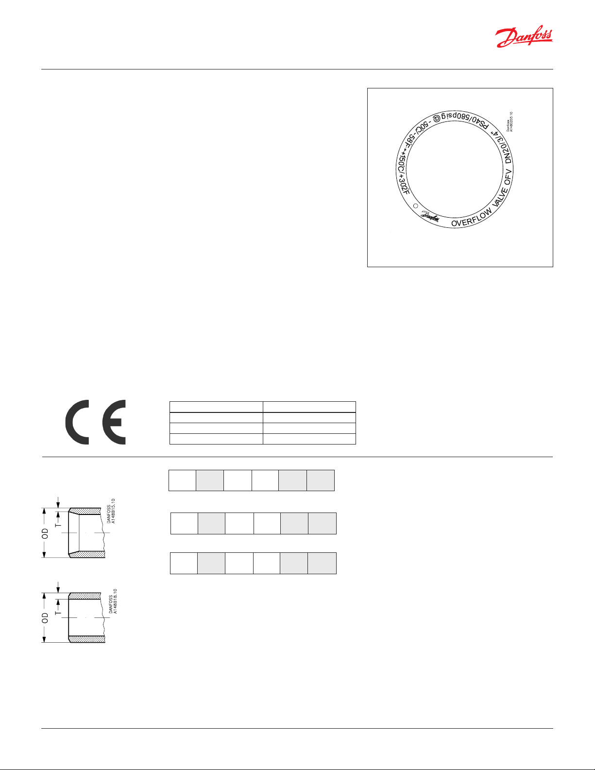
Data sheet | Stainless Steel Valves 15 (½ in.) - 125 ( 5 in.)
Design Connections
Available with the following connections:
• Welding DIN (EN 10220)
• Welding ANSI (B 36.19M)
Packing gland OFV-SS
The stainless steel packing gland comprises a
spring loaded seal packing gland which ensures a
perfect tightness in the range:
-50 – 150 °C / -76 – 302 °F.
The packing glands are equipped with a scraper
ring to prevent penetration of dirt and ice into the
packing gland.
Connections
DIN
ANSI
Pressure Equipment Directive (PED)
OFV valves are approved and CE-marked in
accordance with the Pressure Equipment Directive
- 97/23/EC.
For further details / restrictions - see Installation
Instruction
Installation
The valve is designed to resist very high internal
pressure, but as to the pipe system in general,
hydraulic pressure caused by thermal expansions
in entrapped refrigerants should be avoided. For
further information please see OFV installation
instruction.
OFV-SS
Nominal bore DN≤ 25 mm (1 in.)
Classified for Fluid group I
Category Article 3, paragraph 3
Size
Size
mm
in.ODmmTmmODin.
Butt-weld DIN (EN 10220)
20
¾
25
26.9
1
33.7
Butt-weld ANSI (B 36.19M)
20
¾126.9
25
33.7
2.3
2.6
2.9
3.5
1.059
1.327
1.06
1.33
T
in.
0.091
0.103
0.11
0.14
Example of Marking Ring, Valve type OFV-SS
© Danfoss | DCS (ms) | 2020.01
AI235186440137en-US1101 | 38
Page 39

Data sheet | Stainless Steel Valves 15 (½ in.) - 125 ( 5 in.)
Material specification
EN10088
EN10088
DIN 17440
3
/4 - 1")
AISI 304
AISI 304
Type 17, 683/13 AISI 303
OFV-SS 20 - 25 (
No. Par t Material DIN/EN ISO ASTM
1 Housing Stainless steel X5CrNi18-10
2 Bonnet, Flange Stainless steel X5CrNi18-10
3 Bonnet, Insert Stainless steel
4 Spindle Stainless steel X8CrNiS18-9
5 Cone Steel 9SMn28 Type 2 1213
8
Packing gland
9
Packing washer Non asbestos
12 Bolts Stainless steel A2-70 A2-70 Type 308
13 O-ring
14
Spring
16 Spring washer Steel Steel
17
Spindle seal cap
18
Seal cap gasket
20
Guide piece
21 O-ring Cloroprene (Neoprene)
22
Sealing ring
23 Distance piece Steel
24 O-ring Cloroprene (Neoprene)
Stainless steel
Cloroprene (Neoprene)
Steel
Aluminium
Nylon
Steel
PTFE (Teflon)
© Danfoss | DCS (ms) | 2020.01
AI235186440137en-US1101 | 39
Page 40

Data sheet | Stainless Steel Valves 15 (½ in.) - 125 ( 5 in.)
Dimensions and weights
OFV-SS 20 – 25
Valve size G C C
OFV 20 - 25
OFV 20 (¾ in.)
OFV 25 (1 in.)
Specified weights are approximate values only.
mm
in.
mm
in.
45
1.77
45
1.77
230
9.1
230
9.1
290
11.4
290
11.4
min
∅D
38
1.5
38
1.5
H
60
2.4
60
2.4
Weight
2.0 kg
2.0 kg
© Danfoss | DCS (ms) | 2020.01
AI235186440137en-US1101 | 40
Page 41

Data sheet | Stainless Steel Valves 15 (½ in.) - 125 ( 5 in.)
Ordering
How to order
The table below is used to identify the valve
required.
Please note that the type codes only serve to
identify the valves, some of which may not form
part of the standard product range.
For further information please contact your local
Danfoss Sales Company.
Type codes
Valve type OFV-SS Over Flow Valve
Nominal size in mm 2025DN 20
Connections DAButt-weld connection
Valve housing ANG Angle flow
DN 25
Butt-weld connection
Important!
Where products need to be certified according
to specific certification societies or where higher
pressures are required, the relevant information
should be included at the time of order.
Opening differential pressure
2 – 8 bar / 29 – 116 psi:
Size
mm in
20 ¾ OFV-SS 20 D ANG OVER FLOW VALVE 52BAR 148G3194
25 1 OFV-SS 25 D ANG OVER FLOW VALVE 52BAR 148G3195
25 1 OFV-SS 25 A ANG OVER FLOW VALVE 52BAR 148G3843
Type Code No.
: DIN EN 10220
: ANSI B 36.19M
© Danfoss | DCS (ms) | 2020.01
AI235186440137en-US1101 | 41
Page 42
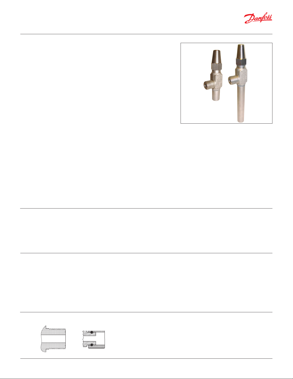
Data sheet | Stainless Steel Valves 15 (½ in.) - 125 ( 5 in.)
Gauge valve
SNV-SS
Features
SNV-SS
SNV-SS valves are designed to meet all industrial
refrigeration application requirements.
Designed as service valves they provide
favourable flow characteristics.
• Applicable to HCFC, non flammable HFC,
R717 (Ammonia) and R744 (CO2).
• Suitable for "heavy duty" industrial applications
having a very sturdy and safe design including
high pressures and wide temperature range.
• SNV-SS valves have backseating (metal to metal).
• Compact and light valve for easy handling and
installation
• No special flow direction required.
• Provide high flow characteristics.
• Each valve type is clearly marked with type and
size.
• Housing and bonnet material is (stainless steel
according to requirements of the Pressure
Equipment Directive and other international
classification authorities.
• Valve safety is enhanced with the spindle being
secured such that it cannot be unscrewed.
• Max. operating pressure:
52 bar g / 754 psig
Valves for higher operating pressure available on
request
• Full temperature range:
-60 – 150 °C / -76 – 302 °F
• Classification: DNV, CRN, BV, EAC etc.
To get an updated list of certification on the
products please contact your local Danfoss Sales
Company.
Technical data • Refrigerants
Applicable to HCFC, non flammable HFC,
R717 (Ammonia) and R744 (CO2). For further
information please see installation instruction
for SNV-SS.
For further information please contact your
local Danfoss Sales Company.
Design
Connections
Available with the following connections:
• G
Housing
Made of stainless steel, approved for low
temperature operations.
Spindle
Equipped with stainless steel spindle, which is
ideal for O-ring sealing.
Connections
2
G 1/
• Temperature range
-60 – 150 °C / -76 – 302 °F.
• Maximum working pressure
The valve is designed for: Maximum operating
pressure of 52 bar g / 754 psig.
Valves for higher operating pressure available
on request.
Installation
No special flow direction is required. The valve is
designed to withstand high internal pres sures.
However, the piping system in general should be
designed to avoid liquid traps and reduce the risk
of hydraulic pressure caused by thermal expansion.
For further in formation refer to installation
instruction for SNV-SS.
G 1/2”
© Danfoss | DCS (ms) | 2020.01
AI235186440137en-US1101 | 42
Page 43
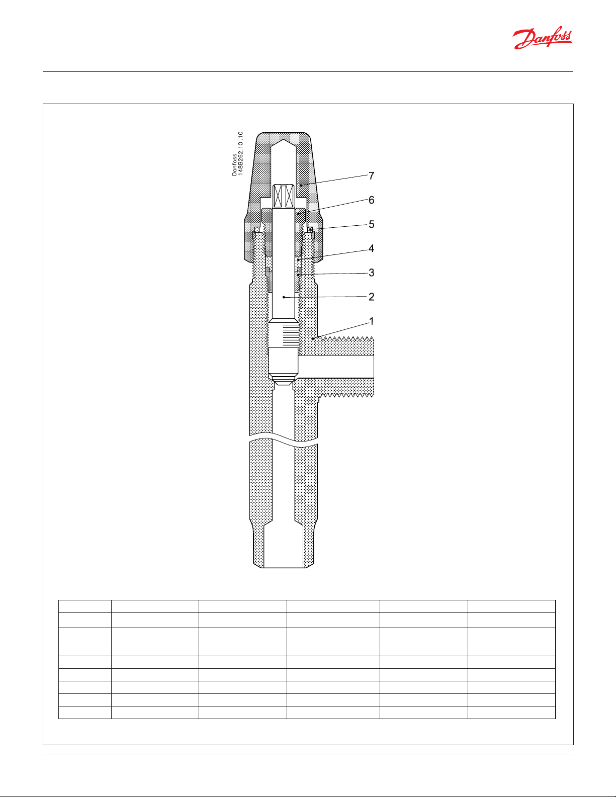
Data sheet | Stainless Steel Valves 15 (½ in.) - 125 ( 5 in.)
Material specification
SNV-SS (extended branch)
No. Part Material EN JIS ASTM
1 Housing Stainless steel (SNV-SS) XSCrNi18-10, 10088 AISI 304
2 Spindle Stainless steel X8CrNiS 18-9
3 Locking ring Steel
4 Sealing ring Teflon
5 Seal cap gasket Nylon
6 Gland nut Steel
7 Seal cap Steel
© Danfoss | DCS (ms) | 2020.01
EN 10088'
SUS 303 AISI 303
DIN 17440 (SNV-SS only)
AI235186440137en-US1101 | 43
Page 44

Data sheet | Stainless Steel Valves 15 (½ in.) - 125 ( 5 in.)
Dimensions and weights
SNV-SS
(extended branch)
Ordering
Type C G L Weight
SNV-SS
SNV-SS
Ext.branch
Specified weights are approximate values only.
mm 131 32 50 0.60 kg
in. 5.16 1.26 1.97 1.32 lb
mm 231 32 150 0.60 kg
in. 9.09 1.26 5.91 1.32 lb
SNV-SS Angle flow
Size Type designation Code number
G ½ W½L50 SNV-SS G1/2-W1/2 L50 148B4265
G ½ W½L150 SNV-SS G1/2-W1/2 L150 148B4266
G ½ W½L50 SNV-SS G1/2-W1/2 L50 - 65 bar 148B4581
G ½ W½L150 SNV-SS G1/2-W1/2 L150 - 65 bar 148B4582
3/8 FTP 3/8 MPT SNV-SS 3/8 FTP-3/8 MPT 148B3750
G ½ – SNV-SS G1/2 Manometer 148B6545
G ½ – Blind nut SS incl. gasket 148B4317
© Danfoss | DCS (ms) | 2020.01
AI235186440137en-US1101 | 44
Page 45
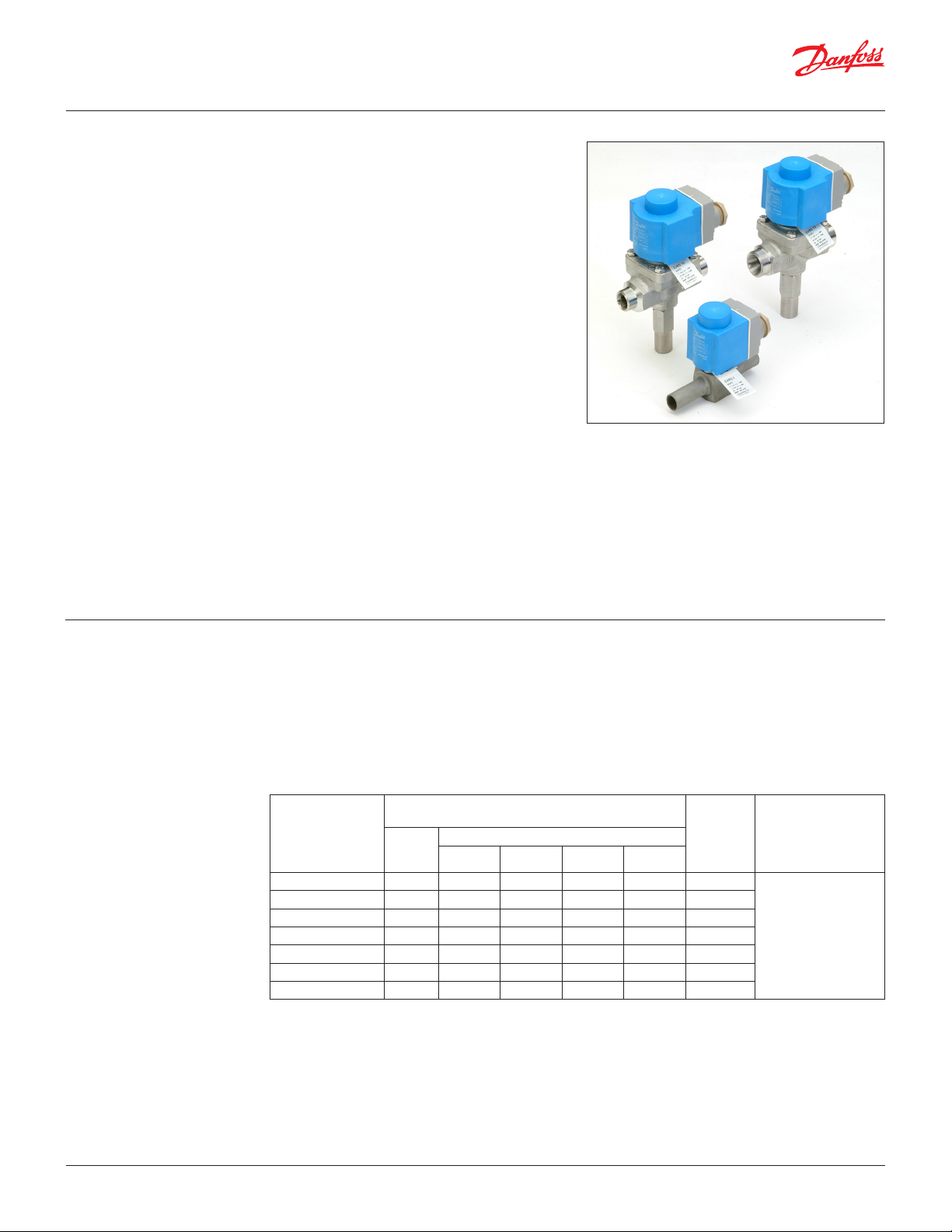
Data sheet | Stainless Steel Valves 15 (½ in.) - 125 ( 5 in.)
Solenoid valves
EVRS and EVRST
Features
EVRS and EVRST
EVRS and EVRST are valves made of stainless
steel.
EVRS 3 is direct operated.
EVRS 10, 15 and 20 are servo operated.
EVRST 10,15 and 20 are forced servo operated
valves used in liquid, suction, hot gas and oil
return lines with ammonia or fluorinated
refrigerants.
EVRS 3 and EVRST are designed for keeping open
at a pressure drop of 0 bar.
EVRS / EVRST 10, 15 and 20 are equipped with
spindel for manual opening.
EVRS and EVRST are supplied as components, i.e.
valve body and coil must be separately ordered.
• Stainless steel valve body and connections
• Max. working pressure 50 barg
• Applicable to HCFC, HFC, R717 (Ammonia) and
R744 (CO2).
• MOPD up to 38 bar with 20 watt a.c. coil
• Wide choice of a.c. and d.c. coils
• Designed for temperatures of media
up to 105 °C
• Manual stem on EVRS and EVRST 10, EVRST 15
and EVRST 20
• Classification: DNV, CRN, BV, EAC etc.
To get an updated list of certification on the
products please contact your local Danfoss Sales
Company.
Technical data Refrigerants
Applicable to HCFC, HFC, R717 (Ammonia) and
R744 (CO2).
Temperature of medium
-40 –105 °C for 10 or 12 watt coil. Max. 130 °C
during defrosting.
-40 – 80 °C for 20 watt coil.
Ambient temperature and enclosure for coil: See "Coils for solenoid valves", lit.no. DKRCC.PD.BS0.A
Type
EVRS 3 0.0 21 25 38 14 0.23
EVRS 10 0.05 21 25 38 18 1.5
EVRST 10 0.0 14 21 38 16 1.5
EVRS 15 0.05 21 25 38 18 2.7
EVRST 15 0.0 14 21 38 18 2.7
EVRS 20 0.05 21 25 38 13 4.5
EVRST 20 0.0 14 21 38 13 4.5
1
) MOPD for media in gas form is approx. 1 bar greater.
2
) The kv value is the water flow in m3/h at a pressure drop in the valve of 1 bar, ρ = 1000 kg/m3.
Opening differential pressure
∆p bar
Max. (MOPD) liquid 1)
10 W a.c. 12 W a.c. 20 W a.c. 20 W d.c.
kv value 2)
m3/h
Max. working pressure
PsMin.
50 barg
© Danfoss | DCS (ms) | 2020.01
AI235186440137en-US1101 | 45
Page 46
Data sheet | Stainless Steel Valves 15 (½ in.) - 125 ( 5 in.)
Technical data
(Continued)
Rated capacity1)
Type
Liquid Suction vapour Hot gas
R717 R22 R134a R404A R410A R717 R22 R134a R404A R410A R717 R22 R134a R404A R410A
EVRS 3 21.8 4.6 4.3 3.2 4.5 6.5 2.1 1.7 1.7 2.3
EVRS/EVRST 10 142.0 30.2 27.8 21.1 29.7 9.0 3.4 2.5 3.1 4.3 42.6 13.9 11.0 11.3 14.9
EVRS/EVRST 15 256.0 54.4 50.1 38.0 53.5 16.1 6.2 4.4 5.5 7.7 76.7 24.9 19.8 20.3 26.7
EVRS/EVRST 20 426.0 90.6 83.5 63.3 89.1 26.9 10.3 7.3 9.2 12.0 128.0 41.5 32.9 33.9
1
) Rated liquid and suction vapour capacity is based on evaporating temperature t
drop across valve ∆p = 0.15 bar.
Rated hot gas capacity is based on condensing temperature tc = 40 °C, pressure drop across valve ∆p = 0.8 bar, hot gas temperature th = 60 °C, and
subcooling of refrigerant ∆t
sub
= 4 K.
kW
= -10 °C, liquid temperature ahead of valve tl = 25 °C, and pressure
e
44.5
Type
R 744 Rated capacity kW 2)
Liquid Suction
EVRS 3 6.65 –
EVRS / EVRST 10 43.3 6.9
EVRS / EVRST 15 78.0 12.4
EVRS / EVRST 20 130.0 20.7
2
) Rated liquid and suction vapour capacity is based on evaporating temperature t
ahead of the vale tl = -8 °C and pressure drop across the valve p = 0.15 bar
For other condition please refer to DIR-Calc or contact your local Danfoss office.
= -40 °C, liquid temperature
e
© Danfoss | DCS (ms) | 2020.01
AI235186440137en-US1101 | 46
Page 47
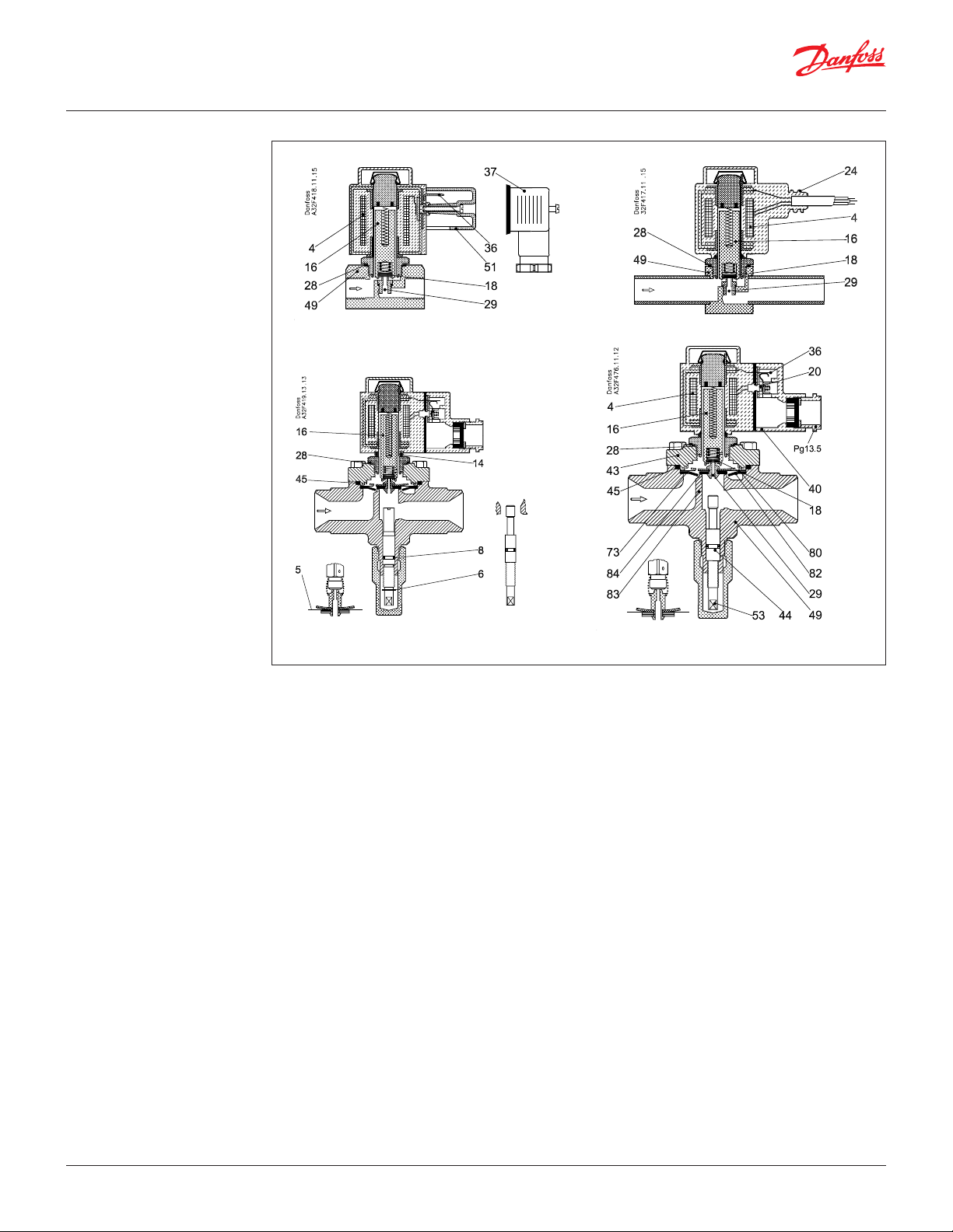
Data sheet | Stainless Steel Valves 15 (½ in.) - 125 ( 5 in.)
Design/Function
4. Coil
16. Armature
18. Pilot valve plate
20. Earth terminal
24. Connection for flexible
steel hose
28. Gasket
29. Pilot orifice
36. DIN plug
40. Terminal box
43. Valve cover
44. O-ring
45. Valve cover gasket
49. Valve body
51. Cover
53. Manual operating spindle
73. Equalization hole
80. Diaphragm
82. Support washer
83. Valve seat
84. Main valve plate
EVRS 3, pipe thread
EVRS / EVRST 10 and 15
The solenoid valve design is based on three
different principles:
1. Direct operation
2. Servo operation
3. Forced servo operation
1. Direct operation
EVRS 3 is directly operated. The valve opens direct for
full flow when the armature (16) moves up into the
magnetic field of the coil. This means that the valve
operates with a min. differential pressure of 0 bar.
The valve plate (18) made of teflon and is fitted direct
to the armature (16).
Inlet pressure acts from above on the armature and
with it the valve plate. Thus, inlet pressure, spring
force and the weight of the armature act to close the
valve when the coil is currentless.
EVRS 3, weld
EVRST EVRS
EVRS / EVRST 20
When current is applied to the coil the armature is
drawn up into the magnetic field and opens the pilot
orifice. This relieves the pressure above the diaphragm
because the space above the diaphragm becomes
connected to the outlet side of the valve.
The differential pressure between inlet and outlet
sides then presses the diaphragm away from the
main orifice which opens to full flow.
Thus a certain minimum differential pressure is
necessary to open the valve and keep it open. For
EVRS 10, 15 and 20 valves this differential pressure
is 0.05 bar.
When current is switched off, the pilot orifice closes.
Then the pressure above the diaphragm rises, via
the equalization holes (73) in the diaphragm, to the
inlet pressure and causes the diaphragm to close
the main orifice.
© Danfoss | DCS (ms) | 2020.01
2. Servo operation
EVRS 10, 15 and 20 are servo operated with a "floating"
diaphragm (80). The pilot orifice (29), which is of
stainless steel, is placed in the centre of the diaphragm.
The teflon pilot valve plate (18) is fitted direct to the
armature (16).
With the coil currentless, the main orifice and
pilot orifice are closed.
The pilot orifice and main orifice are held closed
by the weight of the armature, the armature spring
force and the differential pressure between inlet and
outlet sides.
3. Forced servo operation
EVRST 10, 15 and 20 are forced servo operated
solenoid valves.
Forced servo operation differs from servo operation
in that in a forced servo operated valve the armature
and the diaphragm are connected by a spring. Thus
the armature helps to lift the diaphragm (80) and keep
it lifted so that the pressure drop in the open valve
is the least possible. These types of valves therefore
require no differential pressure to keep them open.
AI235186440137en-US1101 | 47
Page 48

Data sheet | Stainless Steel Valves 15 (½ in.) - 125 ( 5 in.)
Material specification
EVRS 3, Pipe thread
EVRS / EVRST 10 and 15
Solenoid valves Standard
No. Description Type Material Analysis Mat.no. W.no. DIN EN
1 Valve housing
2 Welding tube EVRS 3 Stainless steel X2 CrNiMo 17-12-2 1.4404 17455
3 Cover EVRS (T) 10(15/20 Stainless steel X6 CrNi 18-9 1.4308 17455
4 Armature tube EVRS( T) 3/10/15/20 Stainless steel X2 CrNi 19-11 1.4306 10088
5 Armature tube nut EVRS(T) 3/10/15/20 Stainless steel X8 CrNi 19-11 1.4305 10088
6 Gasket EVRS(T) 3/10/15/20 Rubber Cr
7 Gasket armature tube EVRS(T ) 10/15/20 Al gasket Al 99.5 3.0255 10210
8 Screws EVRS( T) 10/15/20 Stainless steel A2-70 3506
9 Spindle for man. oper. EVRS(T) 10/15/20 Stainless steel X8 CrNiS 18-9 1.4305 10088
10 Gasket EVRS(T) 10/15/20 Rubber Cr
EVRS 3 Stainless steel X8 CrNiS 18-9 1.4305 10088
EVRS (T ) 10/15/20 Stainless steel X6 CrNi 18-9 1.4308 17455
EVRS 3, welded
EVRS / EVRST 20
© Danfoss | DCS (ms) | 2020.01
AI235186440137en-US1101 | 48
Page 49

Data sheet | Stainless Steel Valves 15 (½ in.) - 125 ( 5 in.)
Dimensions and weights
Coil with cable
EVRS 3, pipe thread
EVRS / EVRST 10 and 15
Coil with terminal box
EVRS 3, weld
Coil with DIN plugs
EVRS / EVRST 20
Coil with terminal box
Weight of coil
10 W: approx. 0.3 kg
12 and 20 W: approx. 0.5 kg
© Danfoss | DCS (ms) | 2020.01
L5 max.
Type
EVRS 3, pipe thread 75 85 0.7
EVRS 3, weld 75 85 0.6
EVRS / EVRST 10 75 85 1.2
EVRS / EVRST 15 75 85 1.3
EVRS / EVRST 20 75 85 2.0
10 W
mm mm kg
12 W
20 W
Weight
with coil
AI235186440137en-US1101 | 49
Page 50

Data sheet | Stainless Steel Valves 15 (½ in.) - 125 ( 5 in.)
Ordering Separate valve bodies
Max. working
Type
EVRS 3 50
EVRS 3 50 G 1/
EVRS 10 50
EVRST 10 50
EVRS 15 50
EVRST 15 50
EVRS 20 50 1 032F5437
EVRST 20 50 1 032F5438
Coils See "Coils for solenoid valves", lit.no. DKRCC.PD.BS0.A
pressure Ps
barg
Connection Code no.
Weld
in.
3
/
1
/
1
/
3
/
3
/
8
2
2
4
4
Pipe thread
ISO 228/1
4
With manual
032F3082
032F3083
032F3084
032F3085
stem
Without manual
stem
032F3080
032F3081
© Danfoss | DCS (ms) | 2020.01
AI235186440137en-US1101 | 50
Page 51

Data sheet | Stainless Steel Valves 15 (½ in.) - 125 ( 5 in.)
© Danfoss | DCS (ms) | 2020.01
AI235186440137en-US1101 | 51
Page 52

© Danfoss | DCS (ms) | 2020.01
AI235186440137en-US1101 | 52
 Loading...