

Page 1
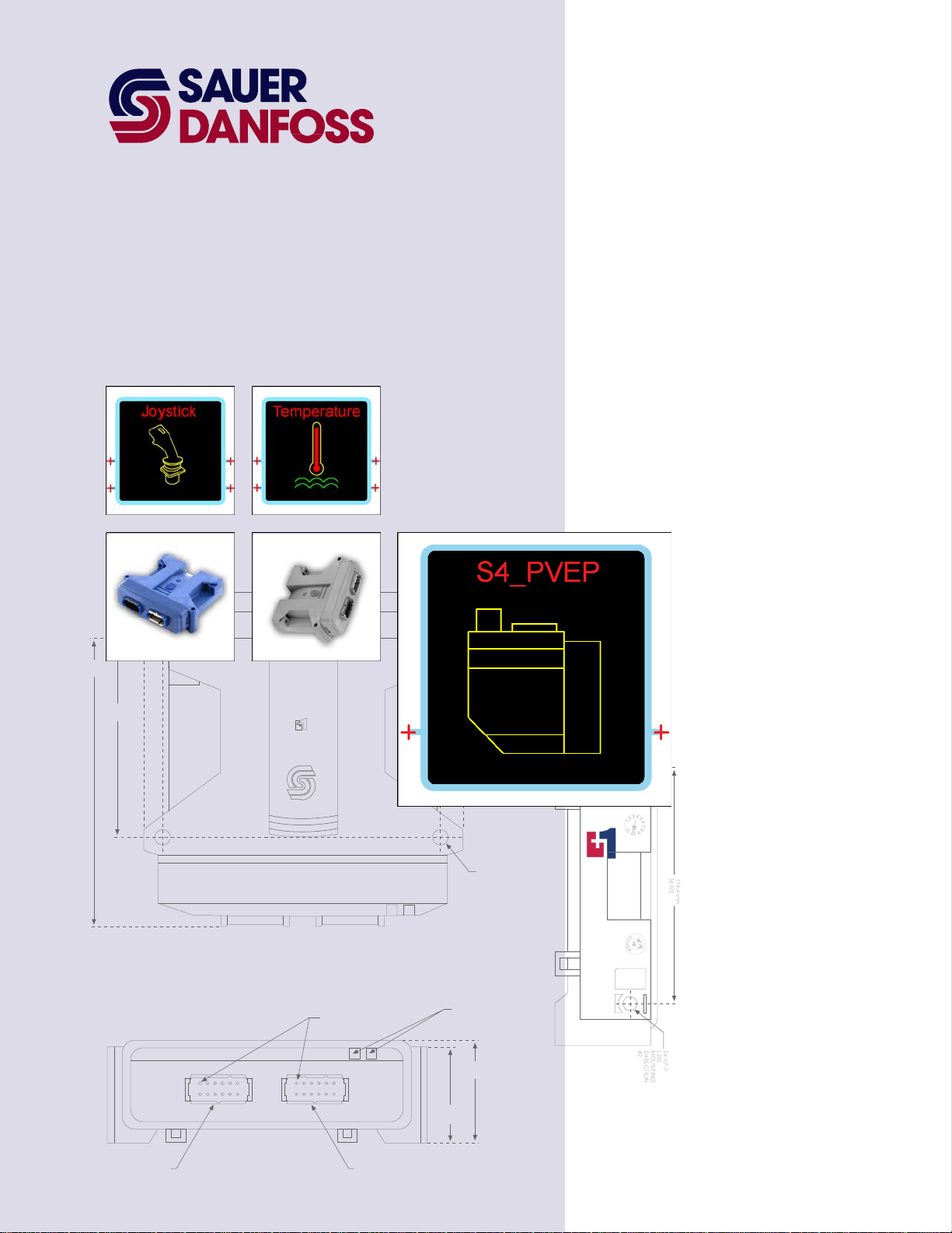
PLUS+1™ GUIDE
Software
PLUS+1 Compliant S4 PVEP Function Block User Manual
142.0 mm
[5.59]
97.0 mm
[3.82]
144.5 mm
5.69
158.2 mm
6.23
PIN #1
INDICATED
2x 25.2 mm
[1.0]
2x 7.0
[.28]
MOUNTING
DIRECTION
#2
LED INDICATO R
LIGHTS
TM
COMPLIANT
CONNECTOR MATES
WITH DEUTCH
CONNECTOR #D TM-06-125A
51.6 mm
47.1 mm
[1.85]
[2.03]
1
12
6
7
1
6
12
7
CONNECTOR MATES
WITH DEUTCH
CONNECTOR #DTM-06-125A
Page 2
PLUS+1 Compliant S4 PVEP Function Block
T
User Manual
About this Manual
Organization
and Headings
o help you quickly find information in this manual, the material is divided into sections,
topics, subtopics, and details, with descriptive headings set in red type. Section titles
appear at the top of every page in large red type.
In the PDF version of this document, clicking an item underlined in blue italic type jumps
you to the referenced page in the document.
Special Text Formatting Controls and indicators are set in bold black type.
Table of Contents
A Table of Contents (TOC) appears on the next page. In the PDF version of this document,
the TOC entries are hyperlinked.
Revision History
Revision Date Comment
Rev CA November 2012
©2012 Sauer-Danfoss. All rights reserved.
Sauer-Danfoss accepts no responsibility for possible errors in catalogs, brochures and other printed material.
Sauer-Danfoss reserves the right to alter its products without prior notice. This also applies to products already
ordered provided that such alterations can be made without affecting agreed specifications.
All trademarks in this material are properties of their respective owners.
PLUS+1, GUIDE, and Sauer-Danfoss are trademarks of the Sauer-Danfoss Group. The PLUS+1 GUIDE, PLUS+1
2
Compliant, and Sauer-Danfoss logotypes are trademarks of the Sauer-Danfoss Group.
11020634 · Rev CA · November 2012
Page 3

PLUS+1 Compliant S4 PVEP Function Block
User Manual
Contents
S4_PVEP Function Block .................................................................................................................................... 4
Overview ......................................................................................................................................................... 4
Inputs ............................................................................................................................................................... 4
Outputs ............................................................................................................................................................ 5
About Function Block Connections...................................................................................................... 6
Status and Fault Logic ............................................................................................................................... 7
About Threshold and Maximum Values ............................................................................................. 8
Setup Inputs .................................................................................................................................................. 9
MC Controller—Input Configuration ................................................................................................. 10
How to Configure a DigIn .............................................................................................................. 10
How to Configure a DigAn ............................................................................................................ 11
How to Configure a MFIn ............................................................................................................... 12
MC Controller—Output Configuration ............................................................................................. 13
How to Configure a MFOut ........................................................................................................... 13
How to Configure a DigOut .......................................................................................................... 14
SC Controller—Input Configuration .................................................................................................. 15
How to Configure a DigAn ............................................................................................................ 15
How to Configure a MFIn ............................................................................................................... 16
SC Controller—Output Configuration .............................................................................................. 17
How to Configure a MFOut ........................................................................................................... 17
How to Configure a DigOut .......................................................................................................... 18
How to Power Two or More S4_PVEP-Type Valve Actuators from a Single DigOut ........ 19
11020634 l Rev CA l November 2012
3
Page 4
PLUS+1 Compliant S4 PVEP Function Block
User Manual
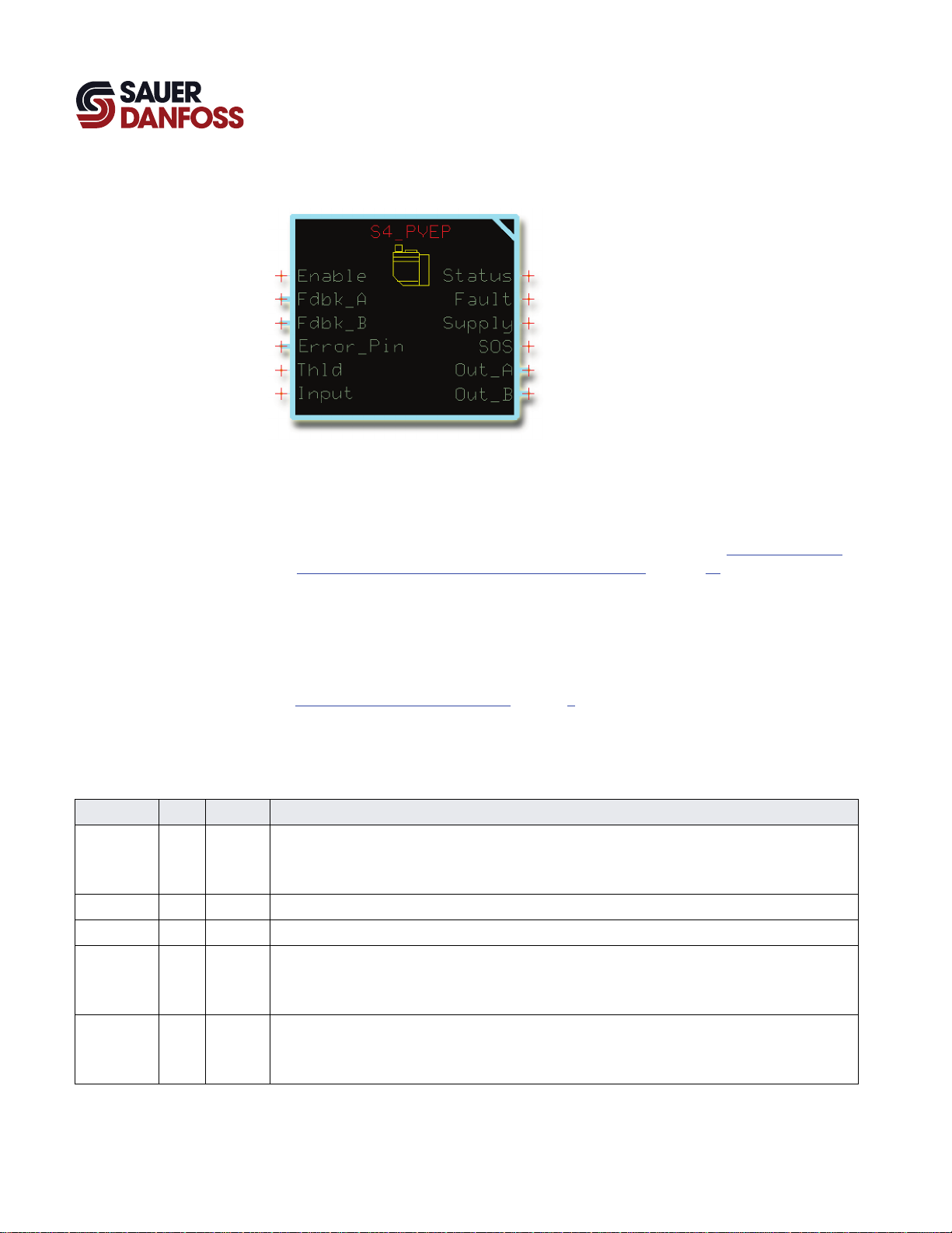
Overview
S4_PVEP Function Block
This function block controls the output of a Sauer-Danfoss PVEP valve actuator.
If you need to:
• Power two or more PVEP-type actuators from a single DigOut, see How to Power Two
or More PVEP-Type Valve Actuators from a Single DigOut on page 19.
• Power two or more PVEP-type actuators from a single MFOut on an MC controller,
you must use a PVE_Power_MF function block for power management.
For more information about this function block, refer to the Plus+1 Compliant PVE
Power MF Function Block User Manual (Sauer-Danfoss part 11007213).
See About Function Block Connections on page 6 for more about this function block’s
signals and connections.
Inputs
Function Block Inputs
Input Type Range Description
Enable BOOL —— Enables the function block’s Output.
– T = Enables the Output.
– F = Disables the Output.
Fdbk_A BOOL —— Reports the status of the MFOut used by the function block’s Out_A.
Fdbk_B BOOL —— Reports the status of the MFOut used by the function block’s Out_B.
Error_Pin —— —— Monitors the input from the valve actuator’s Error_Pin.
The valve actuator outputs a T if an error occurs in the actuator.
By default, a T turns off the function block’s Output.
Thld U16 0–8000 Sets the threshold values of Output produced by Input commands of –1 and +1.
Set as a percentage of upper and lower range of the Output.
10000 = 100.00%.
4
11020634 l Rev CA l November 2012
Page 5
PLUS+1 Compliant S4 PVEP Function Block
User Manual
S4_PVEP Function Block
Function Block Outputs
Function Block Inputs
Input Type Range Description
Input S16 ±10000 Specifies the requested Out_A and Out_B.
– +10000 = Commands the full travel of the valve actuator spool in Direction B.
– 0 = Commands the valve actuator or spool to a neutral position.
– –10000 = Commands the full travel of the valve actuator spool in Direction A.
Outputs
Output Type Range Description
Status U16 —— Reports the status of the function block.
This output follows the standard bitwise scheme described in the Basic Function Blocks Library User’s Manual (Sauer-
Danfoss part 10103408).
Fault U16 —— Reports function block faults.
This output follows the standard bitwise scheme described in the Basic Function Blocks Library User’s Manual (Sauer-
Danfoss part 10103408).
Supply BOOL —— Controls the MFOut or DigOut that supplies power to the Power pin on a valve actuator.
AND the Supply output with the SOS output when you use a single MFOut or DigOut to supply power to two or
more valve actuators.
– T = Requests power on.
– F = Requests power off.
SOS BOOL —— Not required when you control a just one valve actuator.
AND the SOS output with the Supply output when you use a single MFOut or DigOut to supply power to two or
more valve actuators.
– T = Requests power on.
– F = Requests power off.
Out_A U16 0-8000 Outputs a bus with an OutputValue signal that commands the valve actuator in the Out_A direction.
Out_B U16 0-8000 Outputs a bus with an OutputValue signal that commands the valve actuator in the Out_B direction.
11020634 l Rev CA l November 2012
5
Page 6
PLUS+1 Compliant S4 PVEP Function Block
User Manual
S4_PVEP Function Block
Function Block Connections
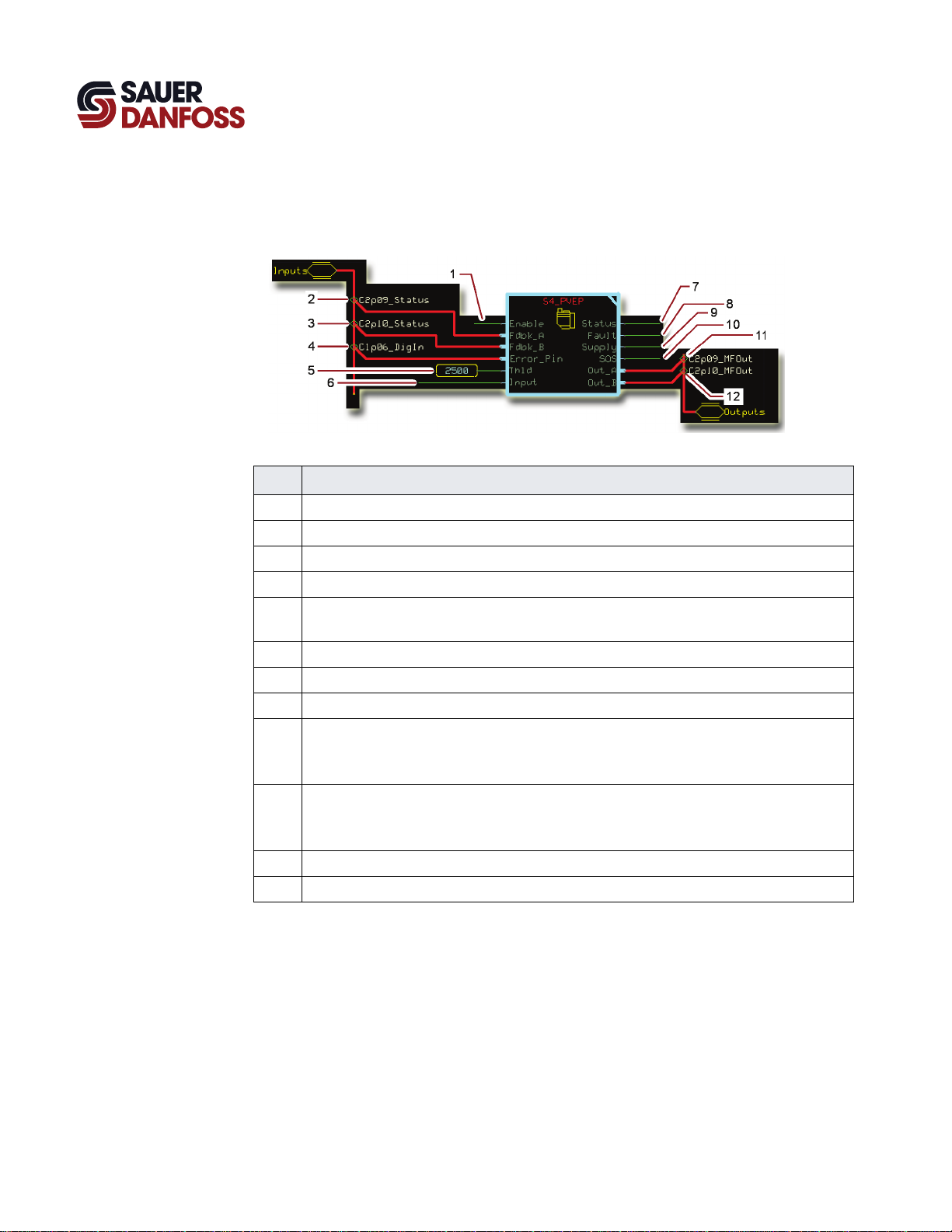
About Function Block Connections
Item Description
1 A T input enables the function block’s Out_A and Out_B.
2 Reports the status of the MFOut used by the Out_A.
3 Reports the status of the MFOut used by the Out_B.
4 Reports the status of the Error_Pin on the valve actuator.
5 Sets the threshold values produced by an Input of ±1. The Thld value is a percentage of the upper and
6 Input for an S16 signal that commands Out_A and Out_B.
7 Reports the status of the function block.
8 Reports function block faults.
9 Powers the valve actuator.
10 AND this output with the Supply output when you use a single MFOut or DigOut to supply power to
11 Commands the valve actuator in the Out_A direction.
12 Commands the valve actuator in the Out_B direction.
lower Out_A and Out_B ranges.
AND this output with the SOS output when you use a single MFOut or DigOut to supply power to two
or more valve actuators.
two or more valve actuators.
No connection is needed when you control a just one valve actuator.
6
11020634 l Rev CA l November 2012
Page 7

PLUS+1 Compliant S4 PVEP Function Block
User Manual
S4_PVEP Function Block
Status Logic
Fault Logic
Status and Fault Logic
Status Bit* Reported While
Parameters are corrupt. 3 Thld < –10000 or > +10000.
*Position of set bit in a 16 bit fault or status code. Bit 1 is the least significant bit. Bit 16 set to 1 identifies a standard Sauer-Danfoss status code or fault
code.
Out_A and Out_B each output an OutputValue signal that goes from 0 to 8000. These
signals command the PVEP actuator in the Out_A and Out_B directions.
Fault Cause Bit* Response Correction
Input value too low. Input < –10000. 1
Input value too high. Input > +10000. 2
Short circuit.
Input is out of range.
Hardware.
*Position of set bit in a 16 bit status or fault code. Bit 1 is the least significant bit. Bit 16 set to 1 identifies a standard Sauer-Danfoss status code or
fault code.
PinStatus = 2 on Fdbk_A or
Fdbk_B bus.
Input <–10000 or
Input > +10000
T input to Error_Pin indicates
error in a PVEP actuator.
4
Out_A or Out_B
held at the value
5 Fix the Input
commanded by
the Input.
6
Fix the Input
Check for short circuit or low resistance between output
pin and ground
Set the Input = 0 and repower the PVEP. For more
information on fault monitoring for the PVEP, see page 5 in
520L0950 Electro-Hydraulic Actuator type PVEP/PVEP-F
Tech Note.
11020634 l Rev CA l November 2012
7
Page 8

PLUS+1 Compliant S4 PVEP Function Block
User Manual
S4_PVEP Function Block
About Threshold and Maximum Values
The following illustration shows plots of Out_A and Out_B between their threshold and
maximum values.
• The maximum output value of Out_A and Out_B is 8000.
• As soon as the Input is –1, Out_A jumps to its threshold value of 2500.
• As soon as the Input is +1, Out_B jumps to its threshold value 2500.
• When the Input is –10000, Out_A reaches its maximum duty cycle of 8000.
• When the Input is +10000, Out_B reaches its maximum duty cycle of 8000.
8
11020634 l Rev CA l November 2012
Page 9

PLUS+1 Compliant S4 PVEP Function Block
User Manual
S4_PVEP Function Block
Setup Inputs
Setup Inputs
As needed, enter the function block to change the FaultReaction and SuppTimeAtNeu
(Supply Time at Neutral) responses.
Output Type Range Description
FaultReaction BOOL —— An error at the valve actuator causes the function block’s Error_Pin input to go T.
The value set here determines the function block’s response to a T on its Error_Pin input.
– T = The function block disables its Output.
– F = The function block does not disable its Output.
SuppTimeAtNeu S16 0-30000 The amount of time that Supply stays on after the function block’s output return to neutral.
– –1 = Supply is always on.
– 1000 = 1000 ms.
11020634 l Rev CA l November 2012
9
Page 10

PLUS+1 Compliant S4 PVEP Function Block
User Manual
S4_PVEP Function Block
MC Controller—Input Configuration
Valve actuators have an Error_Pin output. You can route this output to the function
block’s Error_Pin input through a DigIn, a DigAn, or a MFIn.
How to Configure a DigIn
You must configure a DigIn to accept the signals from the valve actuator’s Error_Pin.
1. In the GUIDE template, enter the Inputs page.
2. Enter the DigIn that receives the input from the valve actuator’s Error_Pin.
3. Make the changes that are shown in the preceding figure.
10
11020634 l Rev CA l November 2012
Page 11

PLUS+1 Compliant S4 PVEP Function Block
User Manual
S4_PVEP Function Block
How to Configure a DigAn
You must configure a DigAn to accept the signals from the valve actuator’s Error_Pin.
1. In the GUIDE template, enter the Inputs page.
2. Enter the DigAn that receives the input from the valve actuator’s Error_Pin.
3. Make the changes that are shown in the preceding figure.
11020634 l Rev CA l November 2012
11
Page 12

PLUS+1 Compliant S4 PVEP Function Block
User Manual
S4_PVEP Function Block
How to Configure a MFIn
You must configure a MFIn to accept the signals from the valve actuator’s Error_Pin.
1. In the GUIDE template, enter the Inputs page.
2. Enter the MFIn that receives the input from the valve actuator’s Error_Pin.
3. Make the changes that are shown in the preceding figure.
12
11020634 l Rev CA l November 2012
Page 13

PLUS+1 Compliant S4 PVEP Function Block
User Manual
S4_PVEP Function Block
MC Controller—Output Configuration
You route this function block’s:
• Out_A and Out_B to a MFOut.
• Supply output to a DigOut.
How to Configure a MFOut
You must configure a MFOut to accept the signals from the function block’s Output.
1. In the GUIDE template, enter the Outputs page.
2. Enter the MFOut that receives the function block’s Out_A or Out_B.
3. Make the changes that are shown in the preceding figure.
11020634 l Rev CA l November 2012
13
Page 14

PLUS+1 Compliant S4 PVEP Function Block
User Manual
S4_PVEP Function Block
How to Configure a DigOut
You must configure a DigOut to accept the signals from the function block’s Supply
output.
1. In the GUIDE template, enter the Outputs page.
2. Enter the DigOut that receives the function block’s Supply output.
3. Make the changes that are shown in the preceding figure.
14
11020634 l Rev CA l November 2012
Page 15

PLUS+1 Compliant S4 PVEP Function Block
User Manual
S4_PVEP Function Block
SC Controller—Input Configuration
Valve actuators have an Error_Pin output. You can route this output to the function
block’s Error_Pin input through either a DigAn or a MFIn.
How to Configure a DigAn
You must configure a DigAn to accept the signals from the valve actuator’s Error_Pin.
1. In the GUIDE template, enter the Inputs page.
2. Enter the DigAn that receives the input from the valve actuator’s Error_Pin.
T Not all DigAn inputs have a Direction configuration. The DigAn input that you modify
may not have a Direction configuration.
3. Make the changes that are shown in the preceding figure.
11020634 l Rev CA l November 2012
15
Page 16

PLUS+1 Compliant S4 PVEP Function Block
User Manual
S4_PVEP Function Block
How to Configure a MFIn
You must configure a MFIn to accept the signals from the valve actuator’s Error_Pin.
1. In the GUIDE template, enter the Inputs page.
2. Enter the MFIn that receives the input from the valve actuator’s Error_Pin.
3. Make the changes that are shown in the preceding figure.
16
11020634 l Rev CA l November 2012
Page 17

PLUS+1 Compliant S4 PVEP Function Block
User Manual
S4_PVEP Function Block
SC Controller—Output Configuration
You route this function block’s:
• Out_A and Out_B to a MFOut.
• Supply output to a DigOut.
How to Configure a MFOut
You must configure a MFOut to accept the signals from the function block’s Output.
1. In the GUIDE template, enter the Outputs page.
2. Enter the MFOut that receives the function block’s Out_A or Out_B.
3. Make the changes that are shown in the preceding figure.
11020634 l Rev CA l November 2012
17
Page 18

PLUS+1 Compliant S4 PVEP Function Block
User Manual
S4_PVEP Function Block
How to Configure a DigOut
You must configure a DigOut to accept the signals from the function block’s Supply
output.
1. In the GUIDE template, enter the Outputs page.
2. Enter the DigOut that receives the function block’s Supply output.
3. Make the changes that are shown in the preceding figure.
18
11020634 l Rev CA l November 2012
Page 19

PLUS+1 Compliant S4 PVEP Function Block
User Manual
S4_PVEP Function Block
Function Block Connections
How to Power Two or More PVEP-Type Valve Actuators from a Single DigOut
Use the following figure as a guide if you want to power two or more PVE-type valve
actuators from a single DigOut.
Item Description
1 Commands.
2 All Supply outputs route to an OR component.
3 All SOS outputs route to an AND component.
4 This AND output goes T when all Supply outputs are T and at least one SOS output is T.
5 To the Power pins on all valve actuators.
6 To the Output pin on a valve actuator.
T You must use a PVE_Power_MF function block if you want to power two or more PVEP-
type valve actuators from a single MFOut on an MC controller. See the Plus+1 Compliant
PVE Power MF Function Block User Manual (Sauer-Danfoss part 11007213).
11020634 l Rev CA l November 2012
19
Page 20

p
Products we offer:
Bent Axis Motors
Closed Circuit Axial Piston Pumps
and Motors
Displays
Electrohydraulic Power Steering
Electrohydraulics
Hydraulic Power Steering
Integrated Systems
Joysticks and Control Handles
Microcontrollers and Software
Open Circuit Axial Piston Pumps
Orbital Motors
PLUS+1™ GUIDE
Proportional Valves
Sensors
Steering
Sauer-Danfoss is a global manufacturer and supplier of highquality hydraulic and electronic components. We specialize in
providing state-of-the-art technology and solutions that excel in
the harsh operating conditions of the mobile off-highway market.
Building on our extensive applications expertise, we work closely
with our customers to ensure exceptional performance for a broad
range of off-highway vehicles.
We help OEMs around the world speed up system development,
reduce costs and bring vehicles to market faster.
Sauer-Danfoss—Your Strongest Partner in Mobile Hydraulics.
Go to www.sauer-danfoss.com for further product information.
Wherever off-highway vehicles are at work, so is Sauer-Danfoss.
We offer expert worldwide support for our customers, ensuring the
best possible solutions for outstanding performance. And with an
extensive network of Global Service Partners, we also provide
comprehensive global service for all of our components.
Transit Mixer Drives
Members of the Sauer-Danfoss Group:
Comatrol
www.comatrol.com
Schwarzmüller-Inverter
www.schwarzmueller-inverter.com
Turolla
www.turollaocg.com
Hydro-Gear
www.hydro-gear.com
Sauer-Danfoss-Daikin
www.sauer-danfoss-daikin.com
Please contact the Sauer-Danfoss re
Local address:
Sauer-Danfoss Inc.
3500 Annapolis Lane North
Minneapolis, MN 55447, USA
Phone: +1 763 509-2000
Fax: +1 763 559-5769
Sauer-Danfoss (US) Company
2800 East 13th Street
Ames, IA 50010, USA
Phone: +1 515 239-6000
Fax: +1 515 239-6618
Sauer-Danfoss GmbH & Co. OHG
Postfach 2460, D-24531 Neumünster
Krokamp 35, D-24539 Neumünster,
Germany
Phone: +49 4321 871-0
Fax: +49 4321 871 122
resentative nearest you.
Sauer-Danfoss ApS
DK-6430 Nordborg, Denmark
Phone: +45 7488 4444
Fax: +45 7488 4400
Sauer-Danfoss-Daikin LTD
Shin-Osaka TERASAKI 3rd Bldg. 6F
1-5-28 Nishimiyahara, Yodogawa-ku
Osaka 532-0004, Japan
Phone: +81 6 6395 6066
Fax: +81 6 6395 8585
11020634 l Rev CA l November 2012
www.sauer-danfoss.com
 Loading...