

Page 1
MAKING MODERN LIVING POSSIBLE
Electrical Installation
S42 Pump
3-Position (FNR) Electric Control
powersolutions.danfoss.com
Page 2

Electrical Installation S42 3-Position (FNR) Electric Control
Revision history Table of revisions
Date Changed Rev
September 2015 Converted to Danfoss layout BA
May 2010 First edition AA
2 L1011710 • Rev BA • September 2015
Page 3

Electrical Installation S42 3-Position (FNR) Electric Control
Contents
Literature references
S42 3-Position (FNR) Electric Control literature references...............................................................................................4
Latest version of technical literature.........................................................................................................................................4
Product overview
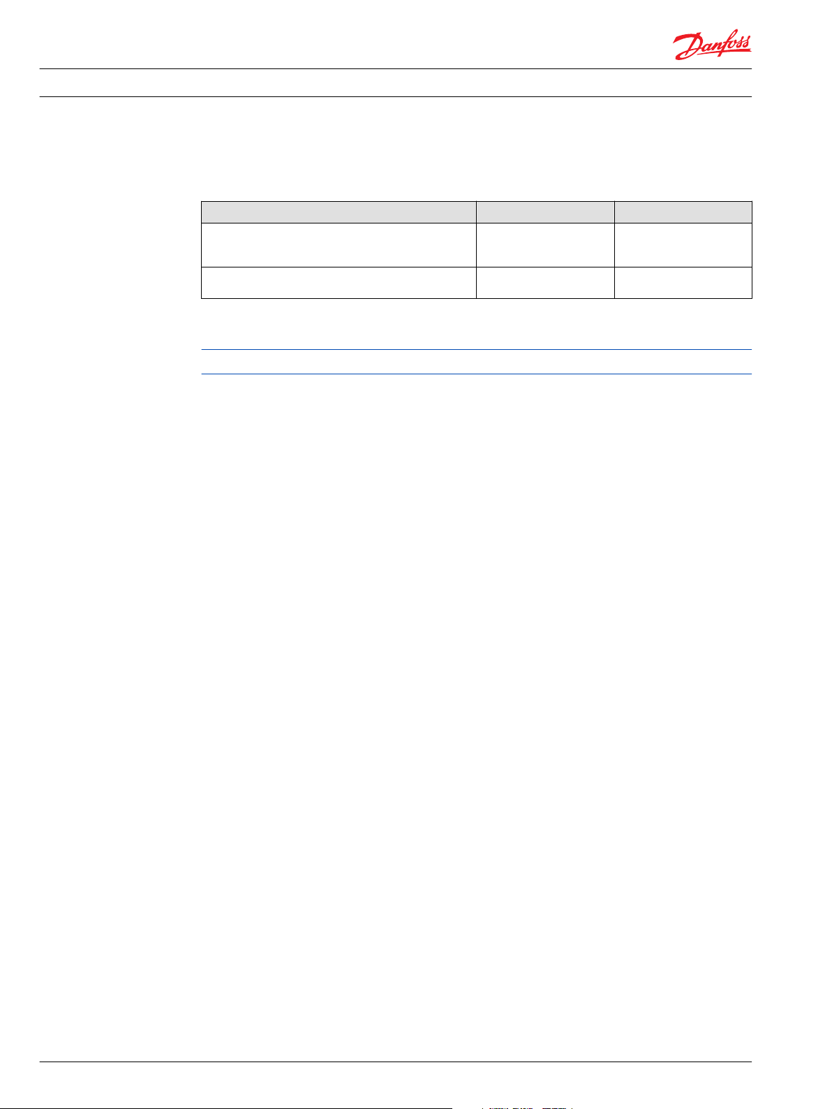
Product image................................................................................................................................................................................... 5
Nomenclature....................................................................................................................................................................................5
Theory of operation.........................................................................................................................................................................6
Hydraulic schematics...................................................................................................................................................................... 6
Electrical specifications.................................................................................................................................................................. 6
Electrical installation
Pinout....................................................................................................................................................................................................7
Pin compatibility...............................................................................................................................................................................7
Input/output matrix........................................................................................................................................................................ 8
Mating connector.............................................................................................................................................................................8
L1011710 • Rev BA • September 2015 3
Page 4
Electrical Installation S42 3-Position (FNR) Electric Control
Literature references
S42 3-Position (FNR) Electric Control literature references
Literature title Description Literature number
S42 Axial Piston Pumps Technical Information Complete product electrical
FNR Control Function Blocks User Manual Compliant function block
Latest version of technical literature
Danfoss product literature is online at: http://powersolutions.danfoss.com/literature/
and mechanical
11022637
specifications
11022881
set-up information
4 L1011710 • Rev BA • September 2015
Page 5
S42
Rotation
Y C D E F Q R G S T U H J K L M N P
Electrical Installation
Product overview
Product image
Nomenclature
S42 3-Position (FNR) Electric Control
S42 3-Position (FNR) Electric Control
Code D options
Option Description
F2NN FNR, bolt-on, 12V, DIN connectors, 41 and 51cc
F4NN FNR, bolt-on, 24V, DIN connectors, 41 and 51cc
F5NN FNR, bolt-on, 12V, AMP Jr connectors, 41 and 51cc
F6NN FNR, integral valves in housing, 12V, DIN connectors, 28 and 32cc
F7NN FNR, integral valves in housing, 24V, DIN connectors, 28 and 32cc
F8NN FNR, integral valves in housing, 12V, AMP Jr connectors, 28 and 32cc
Only certain control options for the S42 pump utilize the 3 Position Control (FNR). Please refer to the
pump's nomenclature to determine if the pump is equipped with the proper option. The nomenclature
can be found on the pump's nametag. For nomenclature details, refer to S42 Axial Piston Pumps Technical
Information, 11022637.
L1011710 • Rev BA • September 2015 5
Page 6
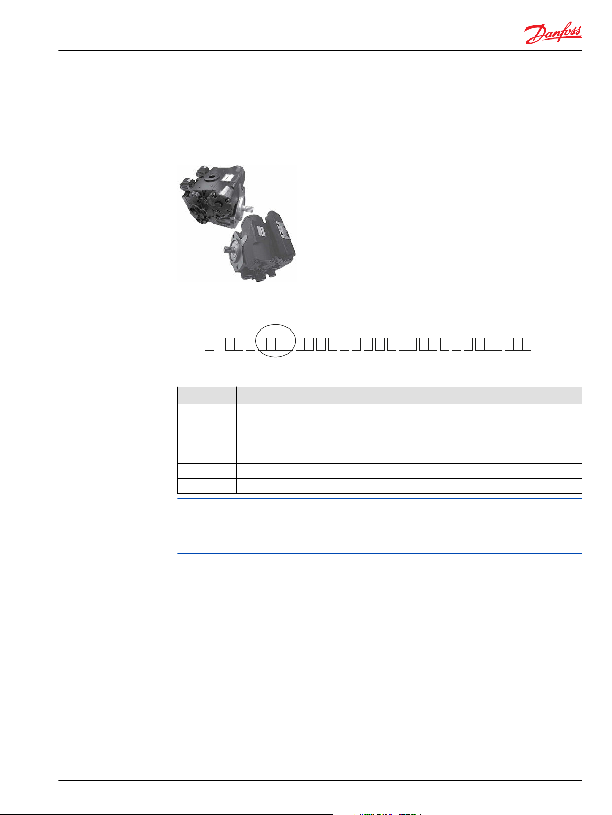
100 %
0
100 %
Voltage Vdc
Displacement
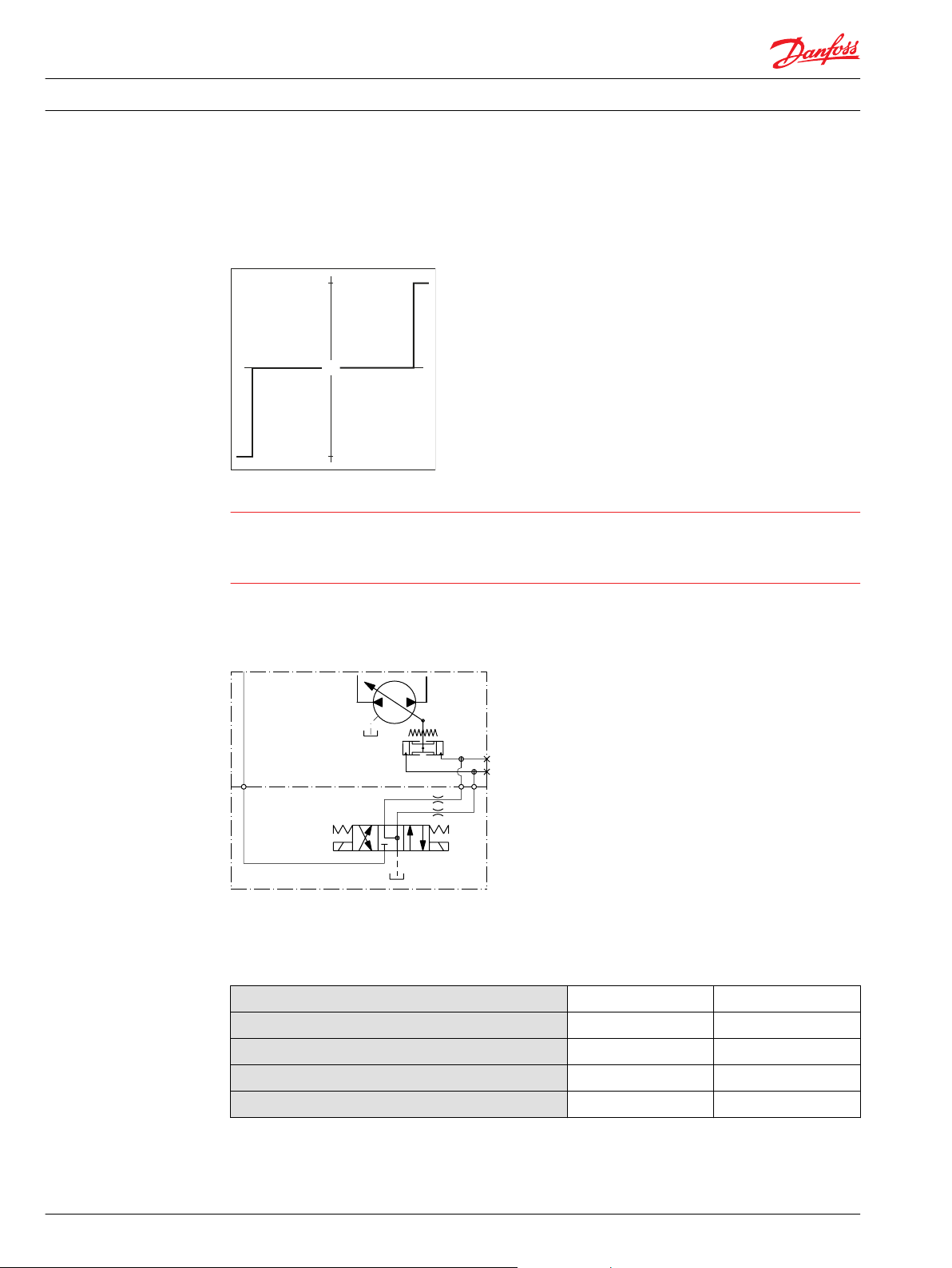
W
M5
M4
a
b
Electrical Installation S42 3-Position (FNR) Electric Control
Product overview
Theory of operation
The 3 Position Control (FNR) control uses an electric input signal to switch the pump to a full stroke
position.
FNR pump displacement versus electrical signal
Warning
Unintended vehicle or machine movement hazard. The loss of hydrostatic drive line power, in any mode
of operation (forward, neutral, or reverse) may cause the system to lose hydrostatic braking capacity. You
must provide a braking system, redundant to the hydrostatic transmission, sufficient to stop and hold the
vehicle or machine in the event of hydrostatic drive power loss.
Hydraulic schematics
Electrical specifications
FNR hydraulic schematic
S42 FNR electrical specifications
Voltage
Minimum supply voltage
Maximum supply voltage
Rated power
Coil resistance at 20ºC [70ºF]
12 V 24V
9.5 Vdc 19 Vdc
14.6 Vdc 27 Vdc
30 W 30 W
4.8 Ω 19.2 Ω
6 L1011710 • Rev BA • September 2015
Page 7
2 1
1 2
W
Electrical Installation
Electrical installation
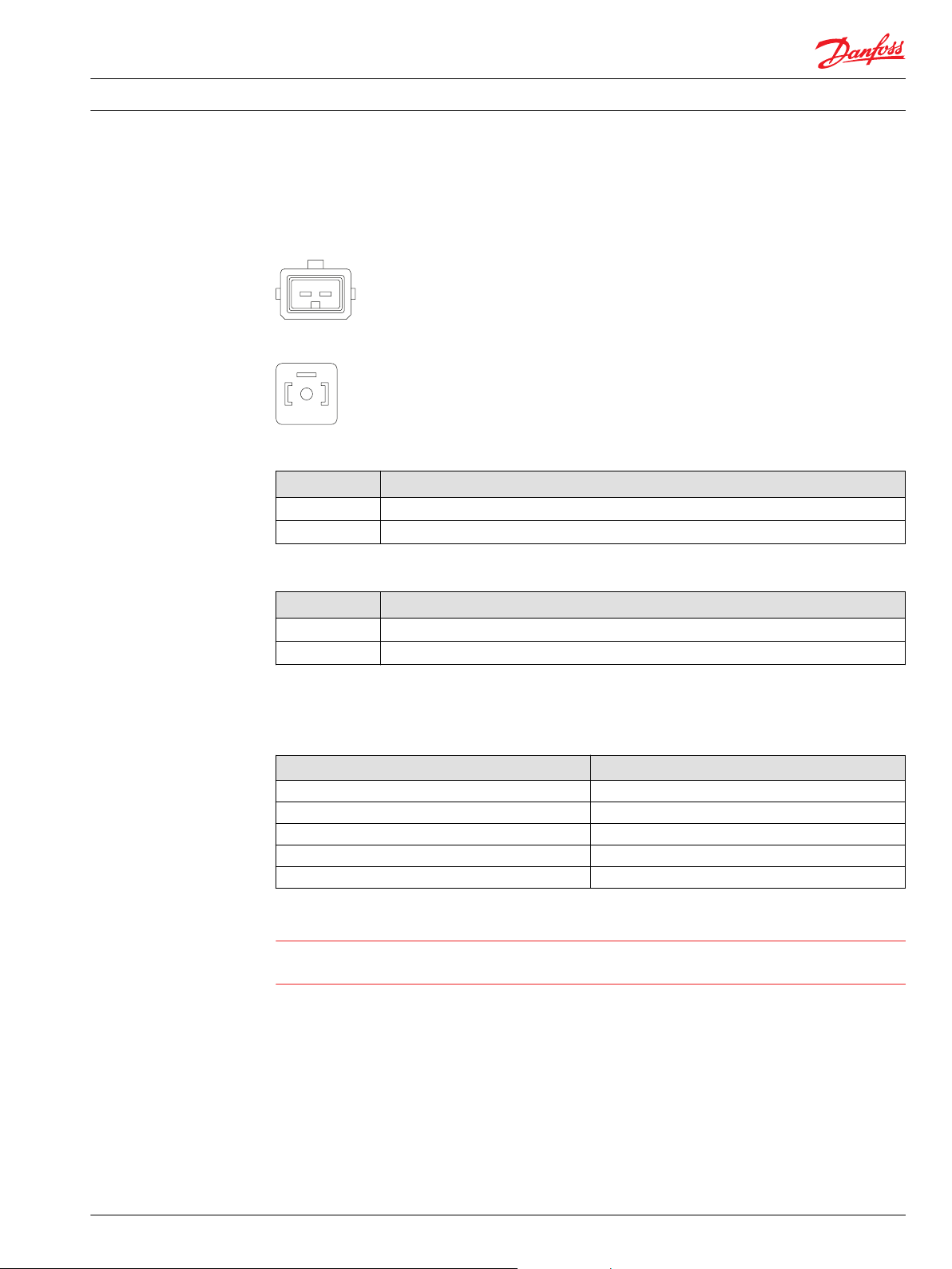
Pinout
S42 3-Position (FNR) Electric Control
AMP Junior Power Timer connector pin location
DIN 43650 connector pin location
Pinout
Pin Description
1, A Voltage signal
2, B Ground
Pin compatibility
Alternative Pinout
Pin Description
1, A Ground
2, B Voltage signal
PLUS+1® module pin type
Pin Function
1, 2, A, B DOUT
1, 2, A, B DOUT/PVG Power
1, 2, A, B PWMOUT/DOUT/PVG Power supply
1, 2, A, B PWMOUT/DOUT/PVGOUT
1, 2, A, B Power ground
Warning
Unintended vehicle or machine movement hazard. Verify the wiring harness to ensure the correct PLUS
+1® pin is properly connected to each control pin.
L1011710 • Rev BA • September 2015 7
Page 8
B
A
B
A
Solenoid b
Solenoid a
Solenoid b
Solenoid a
Electrical Installation S42 3-Position (FNR) Electric Control
Electrical installation
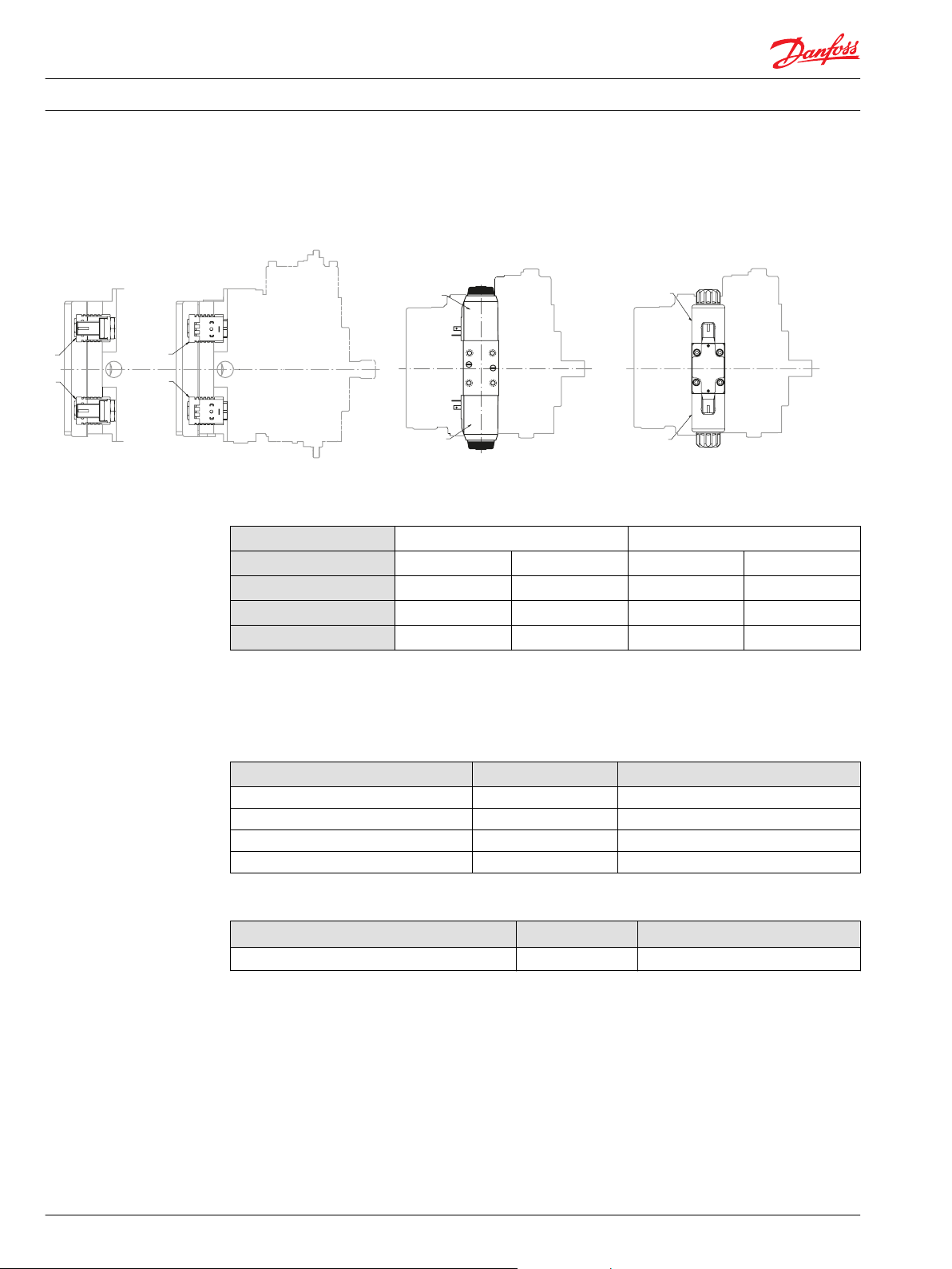
Input/output matrix
28/32cc 3-position FNR Control; 41/51cc 3-position FNR Control DIN Connector; 41/51cc 3-position FNR Control Amp Jr Connector
Pump output flow direction versus control signal
Shaft rotation
Coil energized
Port A flow
Port B flow
Servo port pressurized
*
For coil location, refer to installation drawings in the S42 Axial Piston Pumps Technical Information, 11022637
*
CW CCW
A B A B
Out In In Out
In Out Out In
M4 M5 M4 M5
Mating connector
AMP Junior Power Timer mating connector parts list
Description Quantity Danfoss ordering number
Connector 1 K19816
Connector seal 2 K19818
Connector terminals 2 K27158
Mating connector kit 1 K19815
DIN connector parts list
Description Quantity Danfoss ordering number
Connector/mating connector kit
1 K09129
8 L1011710 • Rev BA • September 2015
Page 9

Electrical Installation S42 3-Position (FNR) Electric Control
L1011710 • Rev BA • September 2015 9
Page 10

Electrical Installation S42 3-Position (FNR) Electric Control
10 L1011710 • Rev BA • September 2015
Page 11

Electrical Installation S42 3-Position (FNR) Electric Control
L1011710 • Rev BA • September 2015 11
Page 12

Danfoss
Power Solutions GmbH & Co. OHG
Krokamp 35
D-24539 Neumünster, Germany
Phone: +49 4321 871 0
Danfoss
Power Solutions ApS
Nordborgvej 81
DK-6430 Nordborg, Denmark
Phone: +45 7488 2222
Danfoss
Power Solutions (US) Company
2800 East 13th Street
Ames, IA 50010, USA
Phone: +1 515 239 6000
Danfoss
Power Solutions Trading
(Shanghai) Co., Ltd.
Building #22, No. 1000 Jin Hai Rd
Jin Qiao, Pudong New District
Shanghai, China 201206
Phone: +86 21 3418 5200
Products we offer:
Comatrol
www.comatrol.com
Schwarzmüller-Inverter
www.schwarzmuellerinverter.com
Turolla
www.turollaocg.com
Hydro-Gear
www.hydro-gear.com
Daikin-Sauer-Danfoss
www.daikin-sauer-danfoss.com
Bent Axis Motors
•
Closed Circuit Axial Piston
•
Pumps and Motors
Displays
•
Electrohydraulic Power
•
Steering
Electrohydraulics
•
Hydraulic Power Steering
•
Integrated Systems
•
Joysticks and Control
•
Handles
Microcontrollers and
•
Software
Open Circuit Axial Piston
•
Pumps
Orbital Motors
•
PLUS+1® GUIDE
•
Proportional Valves
•
Sensors
•
Steering
•
Transit Mixer Drives
•
Danfoss Power Solutions is a global manufacturer and supplier of high-quality hydraulic and
electronic components. We specialize in providing state-of-the-art technology and solutions
that excel in the harsh operating conditions of the mobile off-highway market. Building on
our extensive applications expertise, we work closely with our customers to ensure
exceptional performance for a broad range of off-highway vehicles.
We help OEMs around the world speed up system development, reduce costs and bring
vehicles to market faster.
Danfoss – Your Strongest Partner in Mobile Hydraulics.
Go to www.powersolutions.danfoss.com for further product information.
Wherever off-highway vehicles are at work, so is Danfoss. We offer expert worldwide support
for our customers, ensuring the best possible solutions for outstanding performance. And
with an extensive network of Global Service Partners, we also provide comprehensive global
service for all of our components.
Please contact the Danfoss Power Solution representative nearest you.
Danfoss can accept no responsibility for possible errors in catalogues, brochures and other printed material. Danfoss reserves the right to alter its products without notice. This also applies to
products already on order provided that such alterations can be made without changes being necessary in specifications already agreed.
All trademarks in this material are property of the respective companies. Danfoss and the Danfoss logotype are trademarks of Danfoss A/S. All rights reserved.
L1011710 • Rev BA • September 2015 www.danfoss.com
Local address:
©
Danfoss A/S, 2015
 Loading...