

Page 1
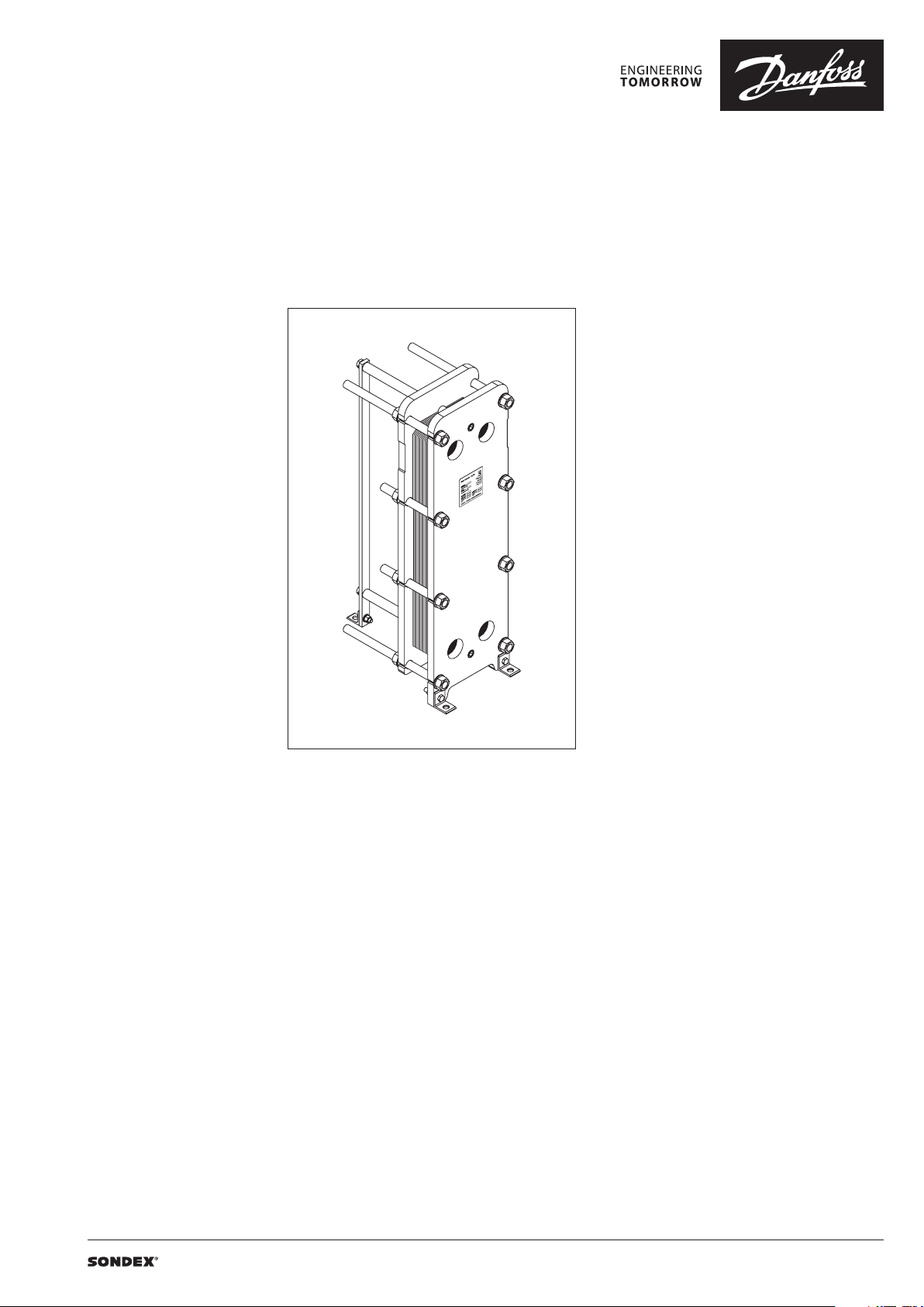
Data sheet
Gasketed Plate Heat Exchangers (DN 150 / 6”)
S41 / S41A / S42 / S62 / S62AE / S62TY / S63 / S79 / S86 / S86SE / S87 / S110 / S110SE
Description
SONDEX® gasketed plate heat exchangers are
the ideal choice for a wide range of applications
across numerous market segments.
We have the largest plate portfolio in the
world, and we customize each heat exchanger
to meet your exact requirements. Innovative
technologies and smart design make our
gasketed plate heat exchangers a stellar
investment.
Benefits:
• Individually customized solution that
perfectly matches your requirements and
lowers your energy consumption.
• High performance and a low pressure
drop eliminate unnecessary burdens on
your system and optimize overall system
performance.
• The design results in a compact solution with
a small footprint, simple installation, and easy
access for maintenance.
Common applications:
• HVAC industry
• Marine/offshore industry
• Dairy/food/beverage industry
• Sugar industry
• Biogas industry
• Pulp and paper industry
• Heavy industry
• Mining industry
• Petrochemical industry
• Chemical industry DN 150
Main data:
• Min. temperature −10 °C
• Max. temperature 180 °C
• Max. working pressure 16 / 25 bar (6 / 10 bar
on request)
• Water and different fluids, steam
• Connection size DN 150 or 6”
Approvals:
• Please contact your local Danfoss/SONDEX®
sales representative for an overview of the
available approvals in your region
Construction standard:
• EN13445 (PED 2014/68/EU)
• ASME sec VIII, Div. 1
| 2019.07 VD.JQ.O1.02 | 1
Page 2
Data sheet S41 / S41A / S42 / S62 / S62AE / S62TY / S63 / S79 / S86 / S86SE / S87 / S110 / S110SE (DN 150 / 6”)
Naming of units
S41A-IS16-21-TKTL89
3)
1)
1)
Type of heat exchanger:
TKTL89 - Plate grouping
21 - Number of plates in the heat exchanger
16 - Design pressure of the heat exchanger
IS - Frame type
2)
41A – Type of heat exchanger
S – Gasketed heat exchanger
41 - …
Letter A shows type of the attachment of gasket to plate:
e.g. 41 (without A) – SonderLock
41A (with A) – Hang-on
SE - SonderLock Energy Saving plate design
AE - Hang-on with smaller channel gap
TY - asymmetric channel design
2)
Description of frame types:
There are few different frame types which can be offered for different applications and duties.
IS – with suspension roller,
IG – without suspension roller,
FS – food/sanitary with suspension roller,
FG - food/sanitary,
ST – simple design of frame with threaded connections
3)
Channel grouping:
In this example, the heat exchanger combines TK and TL channels. The share of TL channels equals
89% of the total number of channels.
The number of channels is defined as “the number of plates - 1”.
TK - short thermal length
TM - medium thermal length
TL - long thermal length
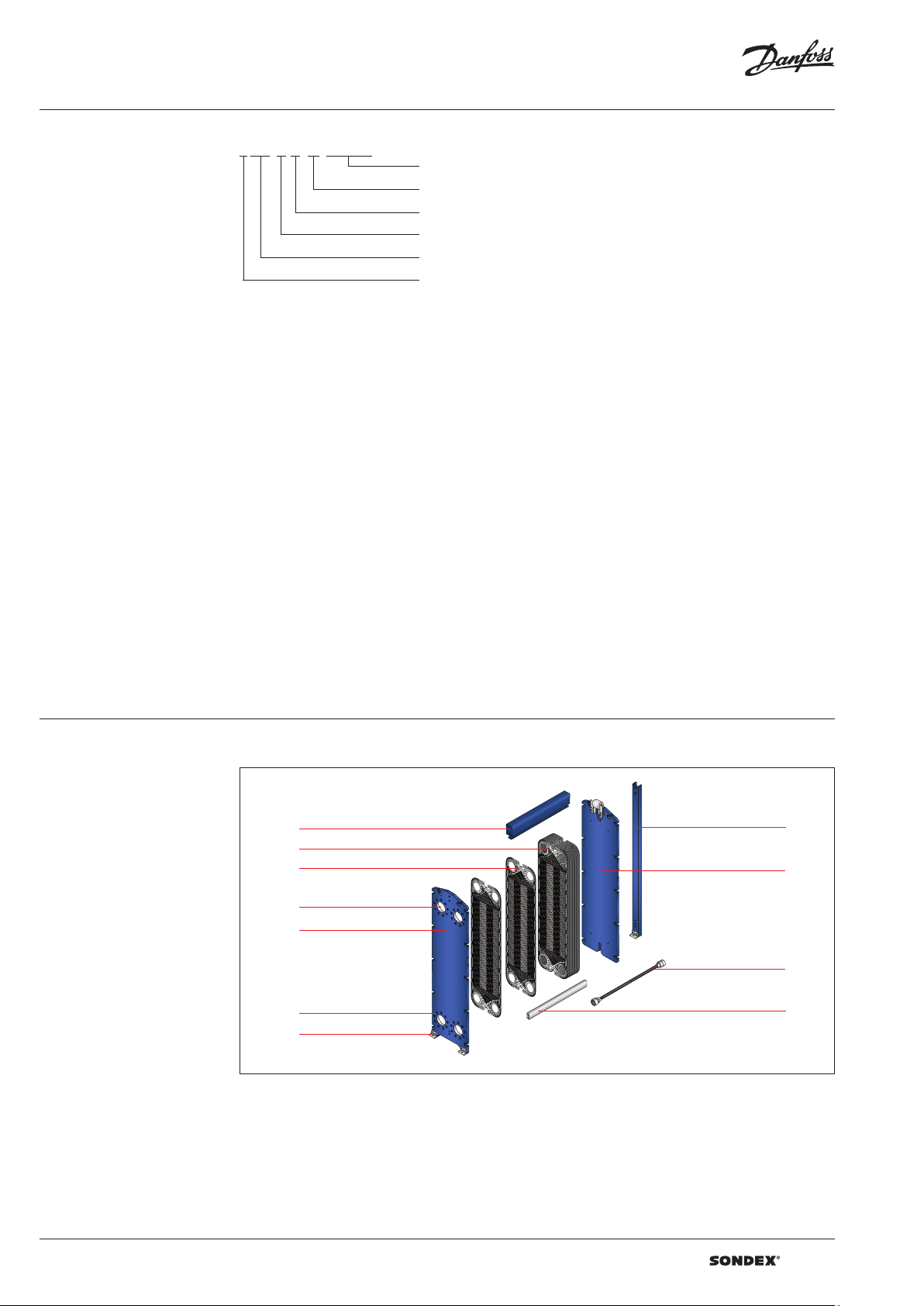
Heat exchanger design
Gasketed heat exchangers consist of
Carrying Bar
Plate Pack
Plate
Connections
Head
Flange Connections
Foundation Feet
Column
Follower
Tie Bolt
Guiding Bar
Anatomy of a SONDEX® plate heat exchanger - IS frame.
2 | VD.JQ.O1.02 | 2019.07
Page 3
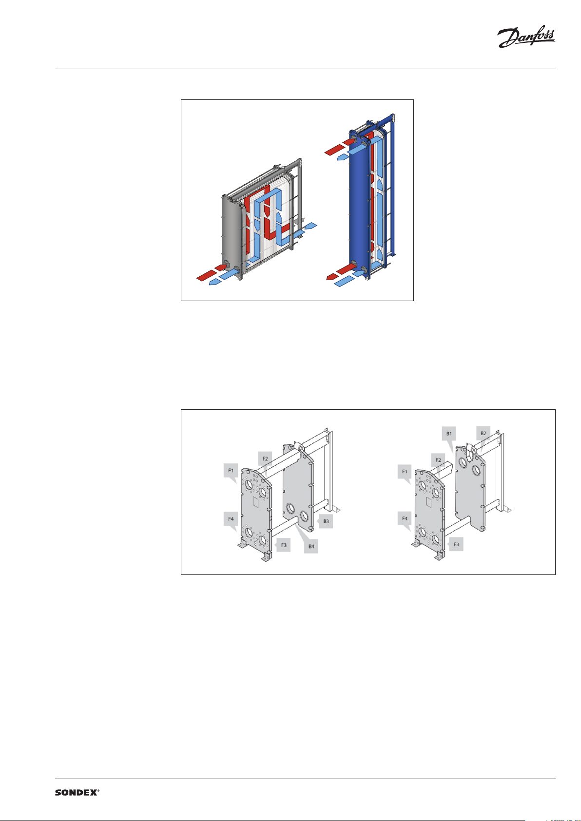
Data sheet S41 / S41A / S42 / S62 / S62AE / S62TY / S63 / S79 / S86 / S86SE / S87 / S110 / S110SE (DN 150 / 6”)
To the left: A multi-pass solution with connections
Heat exchanger design
(continued)
Multi-pass design
on the follower and the head.
To the right: A single-pass solution with
all connections on the head.
Connections
The heat exchanger may have connections on
both front and back end sides of the unit.
Connections on the front-end plate are marked
with F and connections on the back-end plate
are marked with B. The numbers 1, 2, 3 and 4
designate the position of the connection on the
end-plate from the top-left port clockwise.
VD.JQ.O1.02 | 3 | 2019.07
Page 4
Data sheet S41 / S41A / S42 / S62 / S62AE / S62TY / S63 / S79 / S86 / S86SE / S87 / S110 / S110SE (DN 150 / 6”)
SONDEX®
plate
range
Common
Technical data
Heat exchanger S41 / S41A / S42 / S62 / S62AE / S62TY / S63 / S79 / S86 / S86SE / S87 / S110 / S110SE
Typ e
Max. working
pressure
Max. operating
temperature
Min. operating
temperature
Flow medium Water and different fluids, steam
Volume / channel l 1.25 1.6 2.6 2.65/1.55 1. 6 3.1 2.5 2.7 1.6 4.06 3.2 1.98
Connection size DN 150/ 6"
Connection type
Plate material
Plate thickness mm
Gasket material
Gasket attachment t ype Hang-on; Sonder Lock
Liners in connections
Frame
Frame painting
specification
1)
Not available f or all frame variations
2)
SonderSaf e – double plate
S41 S41A S42 S62 S62TY
PN
(bar)
°C
• DN 150/6” flanges. Carbon steel, rubberlined or cladded with AISI 316L (other materials available
on request)
• DN 125 / 5” Dairy union (for food/sanitary industry frames only)
• DN 100 / 4” Dairy union (for food/sanitary industry frames only)
Stainless steel EN 1.440 4 (AISI 316L), EN 1.4301 (AISI 304), SMO254, Hastelloy C276, titanium Gr.1
Other materials available on request
0.4; 0.5; 0.6; 0.7 (ti)
2 x 0.4 SonderSafe plates
Other thicknesses available on request
NBR, EPDM, FKM
Other materials available on request
• Rubber NBR, EPDM, FKM
• Stainless steel EN 1.440 4 (AISI 316L), EN 1.4301 (AISI 304), SMO254, Hastelloy C276, titanium Gr.1
• Painted frame, color RAL 5010 (other colors available on request)
• Stainless steel frame, designed for the sanitary applications (e.g. food and dairy industries)
Painting available for corrosion categories C2L, C4M, C5M
1)
2)
S62AE
S63 S79 S86 S86SE S87 S 110 S110 SE
(6)1), (10)1), 16, 25
Up to 180
-10
Using the right plate for each individual duty
is very important, as it greatly impacts the
efficiency of the entire installation.
It is important that the length of the plates and
the type of pattern match the requirements of
individual thermal duty.
We have developed a wide plate portfolio to
provide the perfect plate and connection size for
any duty.
No application is too small or too big for us - we
provide the optimal technical solution every
time.
Our extensive SONDEX® plate portfolio
includes plates that lie outside the commonly
manufactured plate sizes to cover all thermal
duties optimally.
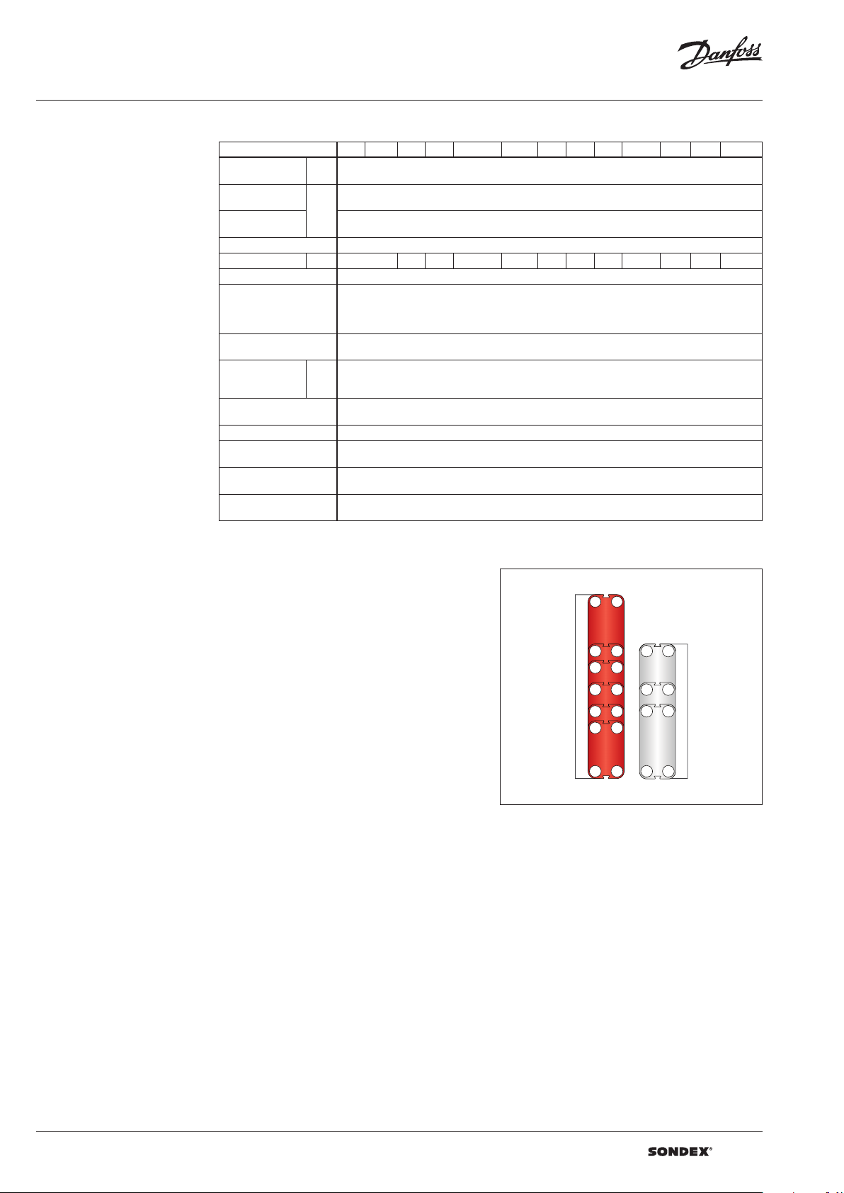
plate
range
4 | VD.JQ.O1.02 | 2019.07
Page 5
Data sheet S41 / S41A / S42 / S62 / S62AE / S62TY / S63 / S79 / S86 / S86SE / S87 / S110 / S110SE (DN 150 / 6”)
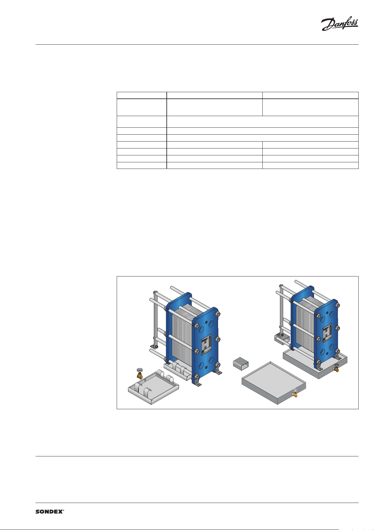
Accessories Insulation
Recommended applications:
The insulation jacket for the plate heat exchanger
is used in different applications with high
temperatures and cooling systems.
Application Heating Cooling
Material
Outer cap
Internal insulation 0.05 mm aluminium foil
Panel fixation Plastic rivets
Temperature 20 … 200 °C -50 … -80 °C
U-value 0.55 W/m2K 0.3 8 W/m2K
Insulation class 3
Heat loss 17.1 W/m
Please note:
Inlet and outl et temperatures in the exch anger have been based on 9 0/50 – 30/70 °C.
1)
The loss of he ating/cooling is stated per m2 surface on the insu lation jacket.
The bottom o f the heat exchanger is not insu lated and this fact has been e xcluded.
A possible loss of ve ntilation, largely dep endent on the mounting of the h eat exchanger, has not been take n into account either.
45 mm mineral wool
Not flammable
DIN EN 4102A2
1 mm aluminium
“Stucco” Embossed
1)
2
Drip trays
Recommended Applications:
The drip tray is available in two types. A “failsafe” solution which prevents water or liquid
from leaking onto the floor, or when the heat
exchangers is dismantled, or opened for
inspection and maintenance. And an insulated
drip tray for cooling applications, which
Materials
Drip tray consists of:
• 1 mm galvanized steel frame
• Hanging brackets in galvanized steel
• 60 mm Polyurethane insulation for cooling
applications
• Draining valve.
collects condensate formed outside of the plate
heat exchanger.
40 mm PU-foam
DIN 4102-1 B2
1)
4
-
Spare parts
Spare parts for gasketed heat exchangers, such
as plates, gaskets, frame parts can be ordered for
maintenance, repair, increasing heat exchanger
capacity, etc.
Selection and ordering Please contact your local SONDEX® or Danfoss
sales representative for the selection and / or
ordering of the heat exchangers, spare parts, and
accessories.
Please contact your local Danfoss or SONDEX®
sales representative to provide you with
information on spare parts available for gasketed
heat exchangers.
For contact information please visit
https://www.danfoss.com/en/contact-us.
VD.JQ.O1.02 | 5 | 2019.07
Page 6

Data sheet S41 / S41A / S42 / S62 / S62AE / S62TY / S63 / S79 / S86 / S86SE / S87 / S110 / S110SE (DN 150 / 6”)
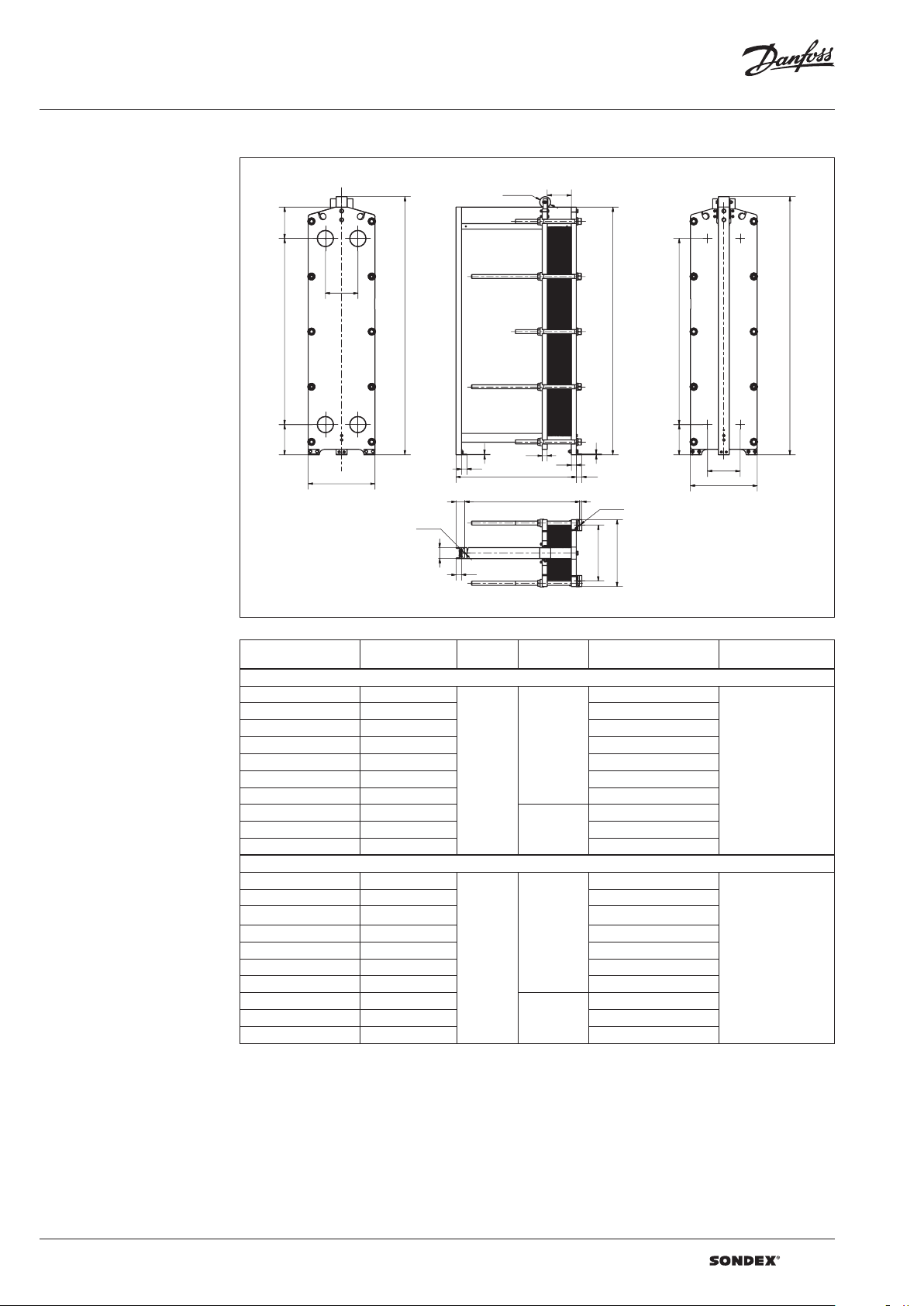
Dimensions
Non-sanitary applications
Any connection can be used for primary side in.
All the rest are made correspondingly.
S41 / S42 frames
296
285
F1
F2
890
F4
F3
50
275
W
80
100
Ø100 L1
5
L + 50
L - 50
Ø18
100
45 45
L
B1
B2
1450
B3
H
B4
7
50
20
540
Ø18
Drawing of S41 IS16 frame
Number of plates
L (frame length)
1)
(mm)
W
(mm)
H
(mm)
Weight max, empt y
(kg)
2)
Connection type
S41 / S41A IS16
3)
7 – 40
41 – 114
3)
115 -170
3)
171-20 7
208 - 300
301 - 392
393 - 485
486 - 670
671 - 855
866 - 1040
3)
3)
3)
3)
3)
3)
3)
695
875
1095 1099
1395 1269
1595 13 81
2095 1663
2595 19 42
640
25.20”
154 6
60.87 ”
3095 2222
4095
5095 3344
6095 3904
1746
68.70”
2783
DN 150 flange or 6”
S41 / S41A IS25
3)
7 – 38
3)
39 – 109
3)
110 – 163
3)
164 – 199
3)
200 – 288
3)
289 – 377
3)
378 - 466
3)
467 - 645
3)
646 - 824
825 - 1002
1)
the indicate d maximum number of pla tes is based on the minimum plate thi ckness allowable for the PN le vel of the unit;
2)
the maximum w eight of the empty unit with t he maximum allowable nu mber of plates;
3)
the indicated ma ximum number of plates is fo r units without intermedi ate frames. Adding an interm ediate frame reduces the
maximum all owable number of plates in t he unit;
*)
PNclass 10 bar is avai lable on request
3)
710
1214
1110 146 4
1410 1652
1610 177 9
2110 2090
2610 2402
640
25.20”
1550
61.02”
3110 2714
4110
5110 3967
6110 4592
175 4
69.06”
3341
DN 150 flange or 6”
6 | VD.JQ.O1.02 | 2019.07
Page 7

Data sheet S41 / S41A / S42 / S62 / S62AE / S62TY / S63 / S79 / S86 / S86SE / S87 / S110 / S110SE (DN 150 / 6”)
Dimensions (continued)
Non-sanitary applications
S41 / S42 frames
296
F1
F2
F4 F3
W
Ø100
L1
285
B1
B2
H
890
50
275
5
45
45
L
1450
B4
B3
50
L + 50
80
100
Ø18
L - 50
20
W
540
100
Ø18
Drawing of S42 IS16 frame
Number of plates
L (frame length)
1)
(mm)
W
(mm)
H
(mm)
Weight max, empt y
(kg)
2)
Connection type
S42 IS16
3)
7 – 31
32 – 89
3)
90 -133
134 -162
163 – 234
235 – 307
308 – 379
380 – 524
525 – 669
670 – 814
3)
3)
3)
3)
3)
3)
3)
3)
695
875
1095 1042
1395 118 2
1595 1275
2095 1507
2595 1740
640
25.20”
154 6
60.87 ”
3095 1971
4095
5095 2901
6095 3365
1746
68.70”
2436
DN 150 flange or 6”
S42 IS25
3)
7 – 30
3)
31 – 87
3)
88 – 130
3)
131 – 159
3)
160 – 230
3)
231 – 302
3)
303 – 373
3)
374 – 516
3)
517 – 659
3)
660 - 802
1)
the indicate d maximum number of pla tes is based on the minimum plate thi ckness allowable for the PN le vel of the unit;
2)
the maximum w eight of the empty unit with t he maximum allowable nu mber of plates;
3)
the indicated ma ximum number of plates is fo r units without intermedi ate frames. Adding an interm ediate frame reduces the
maximum all owable number of plates in t he unit;
*)
PNclass 10 bar is avai lable on request
710
1192
1110 140 2
1410 155 9
1610 1666
2110 1926
2610 219 0
640
25.20”
1550
61.02”
3110 2452
4110
5110 3502
6110 4027
175 4
69.06”
2977
DN 150 flange or 6”
VD.JQ.O1.02 | 7 | 2019.07
Page 8

Data sheet S41 / S41A / S42 / S62 / S62AE / S62TY / S63 / S79 / S86 / S86SE / S87 / S110 / S110SE (DN 150 / 6”)
Dimensions (continued)
Sanitary applications
S62 / S63 frames
296
296
F1
1292
F4
255
730
Ø100
F2
L1
608
B1
B2
H
60
F3
40
40
L - 50
89 /117
min/max
550
L
W
B4
B3
480
60
Drawing of S62 FS10 frame
Number of plates
L (frame length)
1)
(mm)
W
(mm)
H
(mm)
Weight max, empt y
(kg)
2)
Connection type
S62 FS10
3)
7 – 114
115 – 207
208 – 300
301 – 392
393 – 485
486 – 670
3)
3)
3)
3)
3)
110 0
1167
160 0 148 8
2100 1807
2600 2125
800
31. 50”
2059-2099
(81.06-82.64”)
4)
3100 2445
4100 3082
DN 125 dairy union
S62 AE FS10
3)
7 – 140
141 – 254
255 – 368
369 – 481
482 – 595
596 – 822
3)
3)
3)
3)
3)
110 0
1251
160 0 1625
2100 2001
2600 2373
800
31. 50”
20592099
81.0682.64”
4
3100 274 8
4100 3495
DN 125 dairy union
S63 FS10
3)
7 - 96
3)
97 – 175
3)
176 – 253
3)
254 - 331
3)
332 – 409
3)
410 – 565
1)
the indicate d maximum number of pla tes is based on the minimum plate thi ckness allowable for the PN le vel of the unit;
2)
the maximum w eight of the empty unit with t he maximum allowable nu mber of plates;
3)
the indicated ma ximum number of plates is fo r units without intermedi ate frames. Adding an interm ediate frame reduces the
maximum all owable number of plates in t he unit;
4)
the height of the h eat exchanger can be mod ified with special adj ustable feet.
*)
PNclass 10 bar is avai lable on request
110 0
1120
160 0 140 4
2100 1685
2600 1966
800
31. 50”
20592099
81.0682.64”
4
3100 2247
4100 2809
DN 125 dairy union
8 | VD.JQ.O1.02 | 2019.07
Page 9

Data sheet S41 / S41A / S42 / S62 / S62AE / S62TY / S63 / S79 / S86 / S86SE / S87 / S110 / S110SE (DN 150 / 6”)
Dimensions (continued)
Non-sanitary applications
S62 / S63 frames
285
F1 F2
1292
275
296
W
Ø100
1852
1854
F3F4
5
50
50
L
L + 50
80
L - 50
L1
B2
B1
1852
B3 B4
H
7
4545
50
296
W
20
Ø18
508
608
Ø18
Drawing of S62 IS16 frame
Number of plates
1)
L (frame length)
(mm)
W
(mm)
H
(mm)
Weight max,
2)
empty
(kg)
Connection type
S62 (S63) IS16
7 - 403) (7 - 33)
41 - 1123) (34 - 95)
113 - 1673) (96 - 141)
168 - 2033) (142 - 172)
204 - 2943) (173 - 249)
295 - 3853) (250 - 326)
386 - 4763) (327 - 403)
477 - 6583) (4 04 - 556)
659 - 8403) (557 - 710)
841 - 10213) (711 - 864)
3)
3)
3)
3)
3)
3)
3)
3)
3)
3)
695
1107 (1084)
1095 1387 (1333)
1395 160 0 (1517 )
1595 1740 (1640)
2095 2093 (194 8)
2595 2447 (2257)
608
23.94”
194 8
76. 69”
3095 2800 (2565)
4095
5095 4212 (3794)
6095 4916 (4 410)
2148
84. 57”
3505 (3177 )
DN 150 flange or 6”
S62 (S63) IS25
7 - 443) (7 - 31)
45 - 1313) (32 - 91)
132 - 1963) (92 - 137)
197 - 2403) (139 - 167)
241 - 3483) (168 - 243)
349 - 4573) (244 - 318)
458 - 5663) (319 - 394)
567 - 7833) (395 - 546)
784 - 10013) (547 - 697)
1002 - 12183) (395 - 546)
1)
the indicate d maximum number of pla tes is based on the minimum plate thi ckness allowable for the PN le vel of the unit;
2)
the maximum w eight of the empty unit with t he maximum allowable nu mber of plates;
3)
the indicated ma ximum number of plates is fo r units without intermedi ate frames. Adding an interm ediate frame reduces the
maximum all owable number of plates in t he unit;
*)
PNclass 6/10 bar is avail able on request
3)
3)
3)
3)
3)
3)
3)
3)
3)
3)
710
156 6 (1517)
1110 1947 (1794)
1410 2232 (2006)
1610 2425 (2145)
2110 2899 (2497)
2610 3376 (28 44)
640
25.20”
1952
76. 85”
3110 3854 (3195)
4110
5110 5760 (4596)
6110 6 712 (529 9)
2156
84.88”
4805 (3898)
DN 150 flange or 6”
VD.JQ.O1.02 | 9 | 2019.07
Page 10

Data sheet S41 / S41A / S42 / S62 / S62AE / S62TY / S63 / S79 / S86 / S86SE / S87 / S110 / S110SE (DN 150 / 6”)
Dimensions (continued)
Non-sanitary applications
S62AE / S62TY frames
296
F1
F2
1292 285275
F4
F3
W
Ø100 L1
B2
B1
1852
50
50
60
L
60
1852
B3 B4
50
296
W
H
L + 50
80
L - 50
100
20
Ø18
W
540
Ø18
Drawing of S62AE IS16 frame
Number of plates
1)
L (frame length)
(mm)
W
(mm)
H
(mm)
Weight max, empt y
(kg)
2)
Connection type
S62 AE IS16
3)
7 – 48
3)
49 – 137
3)
138 - 204
3)
205 - 248
249 – 360
361 – 471
472 – 582
583 – 804
805 – 1026
1027 – 1248
3)
3)
3)
3)
3)
3)
695
113 4
1095 1469
1395 1721
1595 1887
2095 2307
2595 2725
640
25.20”
194 8
76.6 9”
3095 3143
4095
5095 4813
6095 5648
2148
84. 57”
3977
DN 150 flange or 6”
S62AE IS25
3)
7 – 44
3)
45 – 131
3)
132 – 196
3)
197 – 240
3)
241 – 348
3)
349 – 457
3)
458 – 566
3)
567 – 783
784 – 1001
1002 - 1218
1)
the indicate d maximum number of pla tes is based on the minimum plate thi ckness allowable for the PN le vel of the unit;
2)
the maximum w eight of the empty unit with t he maximum allowable nu mber of plates;
3)
the indicated ma ximum number of plates is fo r units without intermedi ate frames. Adding an interm ediate frame reduces the
maximum all owable number of plates in t he unit;
*)
PNclass 6/10 bar is avail able on request
3)
3)
710
114 8
1110 1529
1410 1815
1610 2008
2110 2481
2610 2958
640
25.20”
1952
76. 85”
3110 3437
4110
5110 5343
6110 6295
2156
84.88”
4387
DN 150 flange or 6”
10 | VD.JQ.O1.02 | 2019.07
Page 11

Data sheet S41 / S41A / S42 / S62 / S62AE / S62TY / S63 / S79 / S86 / S86SE / S87 / S110 / S110SE (DN 150 / 6”)
Dimensions (continued)
Non-sanitary applications
S79 frames
1570 285275
Ø100
F1
F2
H
F4
F3
2132
5
296
50
50
W
L1
B1
B2
2130
B3
50
50
L
7
296
W
1570 269275
B4
L + 50
L - 50 2050
Ø18
Ø18
W
100
508
50
Drawing of S79 IS16 frame
Number of plates
1)
L (frame length)
(mm)
W
(mm)
H
(mm)
Weight max, empt y
(kg)
2)
Connection type
S79 I S10
3)
7 – 42
43 – 116
117 - 172
173 - 209
210 – 301
3)
3)
3)
3)
685
897
1085 117 9
1385 1392
1585 1533
2085 1884
608
23.94”
2226
8 7.6 4”
DN 150 flange or 6”
302 – 394 2585 2238
3)
395 – 487
3085 2592
S79 I S16
3)
7 – 39
3)
40 – 111
3)
112 – 166
3)
167 – 202
3)
203 – 293
3)
294 - 384
3)
385- 475
1)
the indicate d maximum number of pla tes is based on the minimum plate thi ckness allowable for the PN le vel of the unit;
2)
the maximum w eight of the empty unit with t he maximum allowable nu mber of plates;
3)
the indicated ma ximum number of plates is fo r units without intermedi ate frames. Adding an interm ediate frame reduces the
700
1218
110 0 1550
140 0 1801
160 0 1966
2100 2384
608
23.94”
2226
8 7.6 4”
2600 2801
3100 3219
DN 150 flange or 6”
maximum all owable number of plates in t he unit;
VD.JQ.O1.02 | 11 | 2019.07
Page 12

Data sheet S41 / S41A / S42 / S62 / S62AE / S62TY / S63 / S79 / S86 / S86SE / S87 / S110 / S110SE (DN 150 / 6”)
Dimensions (continued)
Non-sanitary applications
S86 / S87 frames
285275
F1
296
1694
L1Ø100
B2
F2
H
2254
F3F4
45
W
50
80 L - 50
45
50L
20
Ø18
1694
275
B1
H
B3
B4
296
W
Ø18
W
100
50
508
Drawing of S37 FG10 frame
Number of plates
1)
L (frame length)
(mm)
W
(mm)
H
(mm)
Weight max, empt y
(kg)
2)
Connection type
S86 (S86SE) IS16
7 – 40 (7 - 44)
41 – 112 (45 - 124)
113 – 167 (125 - 184)
168 – 203 (185 - 224)
204 – 294 (225 - 324)
295 – 385 (325 - 424)
386 – 476 (425 - 524)
477 – 658 (525 - 724)
659 – 840 (725 - 924)
841 – 1021 (925 - 1124)
3)
3)
3)
3)
3)
3)
3)
3)
3)
3)
695
1657 (1373)
1095 1707 (17 55)
1395 1973 (2042)
1595 2148 (22 33)
2095 258 9 ( 2711)
2595 3030 (3188)
608
23.94”
2350
”
3095 3472 (3666)
4095
5095 5237 (5577)
6095 611 6 (6 522 )
2550
”
4354 (4622)
DN 150 flange or 6”
S86 (S86SE) IS25
7 – 36 (7 - 40)
37 – 108 (41 - 118)
109 – 161 (119 - 177)
162 – 197 (178 - 216)
198 – 286 (217 - 314)
287 – 375 (315 - 412)
376 – 465 (413 - 510)
466 – 643 (511 - 706)
644 – 822 (707 - 902)
823 – 1000 (903 - 1099)
1)
the indicate d maximum number of pla tes is based on the minimum plate thi ckness allowable for the PN le vel of the unit;
2)
the maximum w eight of the empty unit with t he maximum allowable nu mber of plates;
3)
the indicated ma ximum number of plates is fo r units without intermedi ate frames. Adding an interm ediate frame reduces the
maximum all owable number of plates in t he unit;
*)
PNclass 6/10 bar is available o n request
3)
3)
3)
3)
3)
3)
3)
3)
3)
3)
710
1880 (189 9)
1110 2286 (2334)
1410 258 4 (2661)
1610 2787 (2879)
2110 3289 (3424)
2610 3790 (3969)
640
25.20”
2354
92.68”
3110 4297 (4514)
4110 5301 (5604)
5110
6110 7312 (7789)
2558
100.71”
6309 (669 4)
DN 150 flange or 6”
12 | VD.JQ.O1.02 | 2019.07
Page 13

Data sheet S41 / S41A / S42 / S62 / S62AE / S62TY / S63 / S79 / S86 / S86SE / S87 / S110 / S110SE (DN 150 / 6”)
Dimensions (continued)
Sanitary applications
S86 / S87 frames
296
F1
F2
296
1694
F4
F3
255
730
Ø100
L1
40 40
L - 50
L
550
608
B1
B2
2395
B3
H
B4
480
116 /15 6
min/max
W
60
Drawing of S86 FS10 frame
Number of plates
L (frame length)
1)
(mm)
W
(mm)
H
(mm)
Weight max, empt y
(kg)
2)
Connection type
S86 FS10
3)
7 – 114
3)
115 – 207
3)
208 - 300
3)
301 - 392
3)
393 – 485
3)
486 – 670
1)
the indicate d maximum number of pla tes is based on the minimum plate thi ckness allowable for the PN le vel of the unit;
2)
the maximum w eight of the empty unit with t he maximum allowable nu mber of plates;
3)
the indicated ma ximum number of plates is fo r units without intermedi ate frames. Adding an interm ediate frame reduces the
maximum all owable number of plates in t he unit;
4)
the height of the h eat exchanger can be mod ified with special adj ustable feet.
*)
PNclass 10 bar is avai lable on request
110 0
620
160 0 1120
2100 1620
2600 2120
800
31. 50”
102. 80104 .37”
26112651
4
3100 2620
4100 3620
DN 125 dairy union
VD.JQ.O1.02 | 13 | 2019.07
Page 14
Data sheet S41 / S41A / S42 / S62 / S62AE / S62TY / S63 / S79 / S86 / S86SE / S87 / S110 / S110SE (DN 150 / 6”)
Dimensions (continued)
Non-sanitary applications
S86 / S87 frames
285
F1
1694
275
Ø100
F2
H
F3F4
5
50
W
80
L1
B2
B1
2254
45
L
7
45
50
20L - 50
Ø18
1694
275
296
W
H
Ø18
100
50
W
508
Drawing of S87 IS16 frame
Number of plates
1)
L (frame length)
(mm)
W
(mm)
H
(mm)
Weight max, empt y
(kg)
2)
Connection type
S87 IS16
3)
7 – 33
34 – 95
96 - 141
142 - 172
173 – 249
250 – 326
327 – 403
404 – 556
557 – 710
711 – 864
3)
3)
3)
3)
3)
3)
3)
3)
3)
695
1328
1095 1637
1395 18 66
1595 2020
2095 2404
2595 2788
608
23.94”
2350
92.52”
3095 317 2
4095
5095 4703
6095 5471
2550
(100.39” )
3935
DN 150 flange or 6”
S87 IS25
3)
7 – 31
3)
32 – 91
3)
92 – 137
3)
138 – 167
3)
168 – 243
3)
244 – 318
3)
319 – 394
3)
395 – 546
3)
547 – 697
3)
698 - 849
1)
the indicate d maximum number of pla tes is based on the minimum plate thi ckness allowable for the PN le vel of the unit;
2)
the maximum w eight of the empty unit with t he maximum allowable nu mber of plates;
3)
the indicated ma ximum number of plates is fo r units without intermedi ate frames. Adding an interm ediate frame reduces the
maximum all owable number of plates in t he unit;
*)
PNclass 10 bar is avai lable on request
710
1855
1110 2203
1410 2467
1610 26 41
2110 3079
2610 35 12
640
25.20”
2534
99.76”
3110 3951
4110
5110 5699
6110 6575
2558
100.71”
4827
DN 150 flange or 6”
14 | VD.JQ.O1.02 | 2019.07
Page 15

Data sheet S41 / S41A / S42 / S62 / S62AE / S62TY / S63 / S79 / S86 / S86SE / S87 / S110 / S110SE (DN 150 / 6”)
Dimensions (continued)
Non-sanitary applications
S110 frames
2852094275
F1
F4
296
Ø100
F2
L1
2654
F3
7
5
50
W
45
L
45
50
L1
B2
B1
H
2094
B3
B4
275
W
L + 50
80
100
L - 50
20
Ø18
W
508
Ø18
Drawing of S110 IS16 frame
Number of plates
1)
L (frame length)
(mm)
W
(mm)
H
(mm)
Weight max, empt y
(kg)
2)
Connection type
S110 (S110SE) IS16
7 – 403) (7 - 43) 695
1628 (1643)
41 – 1123) (44 - 123) 1095 20 63 ( 2117)
113 – 1673) (124 - 183) 1395 2395 (2473)
168 – 2033) (184 - 223) 1595 2613 (2710)
204 – 2943) (224 - 323) 2095 3163 (3304)
295 – 3853) (324 - 423) 2595 3712 (3898)
608
23.94”
2750
108.27 ”
DN 150 flange or 6”
386 – 4763) (424 - 523) 3095 4262 (4491)
477 – 6583) (524 - 723) 4095
659 – 8403) (724 - 923) 5095 6 460 (6865)
841 – 10213) (924 - 1123) 6095 7554 (8052)
2950
116.14 ”
5361 (5678)
S110 (S110 SE ) IS 25
7 – 363) (7 – 39) 710
2045 (2062)
37 – 1083) (40 - 117) 1110 2548 (2600)
109 – 1613) (118 - 176) 1410 2919 (300 6)
162 – 1973) (177 - 215) 1610 3171 (327 5)
198 – 2863) (216 - 313) 2 110 3794 (3950)
287 – 3753) (314 - 411) 2610 4416 (4 625)
640
25.20”
2750
108.27 ”
DN 150 flange or 6”
376 – 4653) (412 - 509) 3110 504 4 (5299)
466 – 6433) (510 - 705) 4110
644 – 8223) (706 - 901) 5110 7541 (7999)
823 – 10003) (902 - 1098) 6110 8789 (9355)
1)
the indicate d maximum number of pla tes is based on the minimum plate thi ckness allowable for the PN le vel of the unit;
2)
the maximum w eight of the empty unit with t he maximum allowable nu mber of plates;
3)
the indicated ma ximum number of plates is fo r units without intermedi ate frames. Adding an interm ediate frame reduces the
maximum all owable number of plates in t he unit;
*)
PNclass 10 bar is avai lable on request
2958
116.4 7”
6289 (6649)
VD.JQ.O1.02 | 15 | 2019.07
Page 16

Data sheet S41 / S41A / S42 / S62 / S62AE / S62TY / S63 / S79 / S86 / S86SE / S87 / S110 / S110SE (DN 150 / 6”)
Dimensions (continued)
Sanitary applications
S110 frame s
29 7.5
2094
256.5
296
F1
F2
Ø100
L1
2646, 5
F3F4
730
W
L - 51.5
L
43
550
min/max
118.5/156. 5
43
W
643
B2
B1
H
B3
B4
480
60
Drawing of S110 FS10 frame
Number of plates
L (frame length)
1)
(mm)
W
(mm)
H
(mm)
Weight max, empt y
(kg)
2)
Connection type
S110 FS10
3)
7 – 114
3)
115 – 206
3)
207 - 299
3)
300 - 392
3)
393 – 484
3)
485 – 669
1)
the indicate d maximum number of pla tes is based on the minimum plate thi ckness allowable for the PN le vel of the unit;
2)
the maximum w eight of the empty unit with t he maximum allowable nu mber of plates;
3)
the indicated ma ximum number of plates is fo r units without intermedi ate frames. Adding an interm ediate frame reduces the
maximum all owable number of plates in t he unit;
4)
the height of the h eat exchanger can be mod ified with special adj ustable feet.
*)
PNclass 10 bar is avai lable on request
110 3
1677
1603 2121
2103 2568
2603 3015
803
[31. 61”]
286 3.5-2901. 5
[112 .74 -114. 23 ”]
4)
3103 3458
4103 4349
DN 125 dairy union
| DHS-SRMT/SI | 2019.0716 | VD.JQ.O1.02
 Loading...