

Page 1
Instruction
Instruction
Pump instruction
PAHT G pumps
PAHT/PAHT G 20-32 and
PAHT G 20/25/32 and
PAHT G 50/63/70/80/90
PAHT/PAHT G 50-90
danfoss.high-pressurepumps.com
hpp.danfoss.com
Page 2

Instruction Pump instruction PAHT G 20-32 and PAHT G 50-90
Table of Contents
1. Identication ...........................................................................3
2. System design ..........................................................................3
2.1 Closed water hydraulic systems, water recirculated ......................................3
2.2 Closed-system design ..................................................................3
2.3 Open-ended systems, water supply from tank ...........................................4
2.4 Open-ended systems with direct water supply...........................................4
2.5 Open-system design ....................................................................4
2.6 guidelines for calculation of pressure losses ...........................................6
3. Building up the pump unit ..............................................................6
3.1 Mounting...............................................................................6
3.2 Direction of rotation ....................................................................7
3.3 Orientation .............................................................................7
3.4 Protection from too high system pressures ..............................................7
3.5 Connections ............................................................................8
3.5.1 PAHT G 20-32 ...........................................................................8
3.5.2 PAHT G 50-90...........................................................................8
4. Initial start-up ...........................................................................9
5. Operation...............................................................................9
5.1 Water quality ...........................................................................9
5.2 Temperature............................................................................9
5.3 Pressure ................................................................................9
5.4 Dry running............................................................................10
5.5 Disconnection .........................................................................10
5.6 Storage ................................................................................10
5.6.1 Water hydraulic systems, water recirculated.............................................10
5.6.2 Open-ended systems with water supply from tank. .....................................10
5.6.3 Open-ended systems with direct water supply. .........................................10
6. Service.................................................................................10
7. Recommended service intervals........................................................11
7.1 General information....................................................................11
7.2 Inspection of pump parts ..............................................................11
7.3 How to inspect the pump ..............................................................11
2
180R9381 | AN077186502937en-000401 | Instruction PAHT G 20-90 | 08.2020
Page 3
Instruction Pump instruction PAHT G 20-32 and PAHT G 50-90
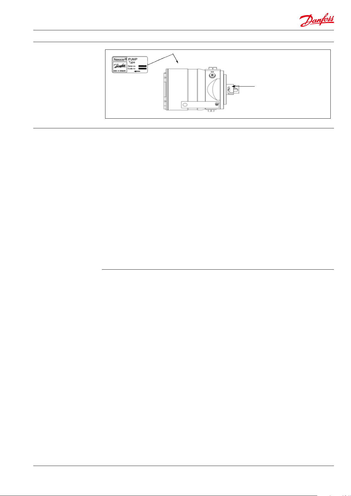
1. Identication
PAHT G
Protective cap must be removed
and thrown away before usage.
2. System design
Systems can be either:
• Water hydraulic systems, in which the water
is recirculated back to tank.
• Open-ended systems with water supply
from a tank.
• Open-ended systems with direct watersupply (boosted pressure).
The design of the system must ensure that
selfemptying of the pump during standstill is
avoided.
The minimum boost pressure is 2 barg (29 psig)
and the maximum peak pressure is 20 barg
(290 psig). The recommended normal boost
pressure is 2-6 barg (29-87 psig) (3-7 barg
[43.5-101.5 psig] abs).
2.2 Closed-system design
A Inlet line:
Dimension the inlet line to obtain minimum pressure loss (large ow, minimum
pipe length, minimum number of bends/
connections, and ttings with small
pressure losses).
B Inlet filter:
Install the inlet lter (1) in front of the tank
(2). Place the tank above pump and pump
inlet. Please consult the Danfoss lter data
sheet for guidance on how to select the
right lter.
C Monitoring pressure switch:
Install the monitoring pressure switch (3) in
front of the lter (1). Set the maximum inlet
pressure to 2 barg (29.0 psig). The monitoring pressure switch will stop the pump (5) if
inlet pressure is higher than 2 barg
(29.0 psig), indicating that the lter element
must be changed.
D Monitoring temperature switch:
Install the monitoring temperature switch
(4) in the tank. Set the temperature value
according to technical data, item 4. The
monitoring temperature stops the pump if
inlet temperature is higher than the set
value.
If it is unknown what the peak inlet pressure can
be, then there should be a 15 barg (218 psig)
safety relief valve on the inlet side of the pump.
Note: All mentioned pressures refer to
measures in the respective pump gauge ports.
The inlet pressure of the pump must never
exceed the outlet pressure. This may typically
occur in boosted or open-ended systems with
supply direct from the tap and where a bypass
valve is activated.
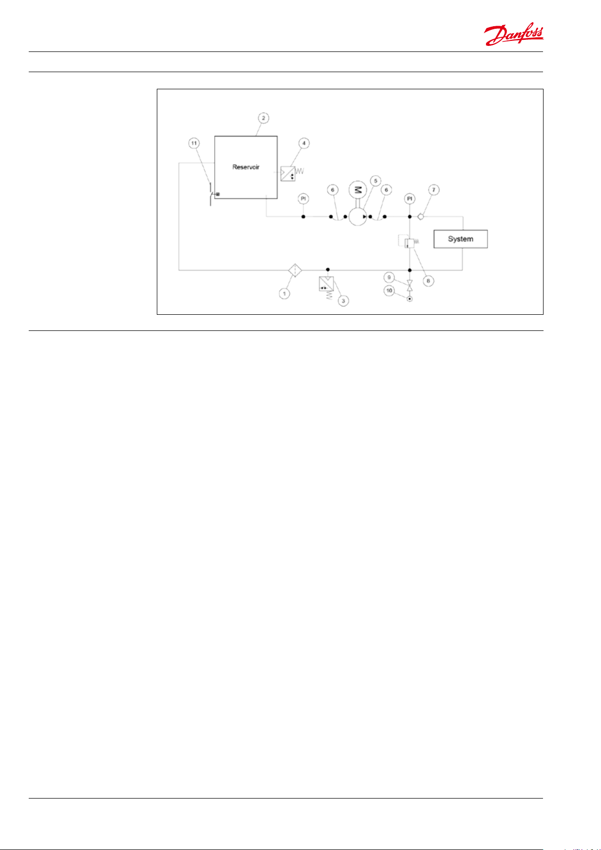
2.1 Closed water hydraulic systems, water
recirculated
(The numbers 1- 3 refer to the drawing below ).
In order to eliminate the risk of cavitation, always
ensure a minimum inlet pressure of 0 barg
(0 psig) (1 barg [14.5 psig] abs) by observing the
following guidelines:
E Hoses:
Always use exible hoses (6) to minimize
vibrations and noise.
F Inlet pressure:
In order to eliminate the risk of cavitation
and other pump damage, pump inlet
pressure must be maintained according to
specications described in item 4, technical
data.
G Non-return valve (7):
Should be installed after the outlet to
prevent pump backspin, which may ruin
the pump.
H Pressure relief valve:
As the Danfoss PAHT pump begins to
create pressure and ow immediately after
start-up regardless of any counter pressure,
a pressure relief valve (8) should be
installed to prevent system damage.
I System water filling:
To ensure proper ltration of new water
(10) supplied to the system, always use the
lling valve (9).
J Minimum level switch:
Install the minimum level switch (11) above
the outlet of the reservoir. The level switch
must stop the pump if the water in the
reservoir is below the switch, which
indicates that the reservoir is empty.
180R9381 | AN077186502937en-000401 | Instruction PAHT G 20-90 | 08.2020
3
Page 4
Instruction Pump instruction PAHT G 20-32 and PAHT G 50-90
2.3 Open-ended systems, water supply from
tank
(The numbers 1-3 refer to the drawing below ).
In order to eliminate the risk of cavitation, always
ensure a minimum inlet pressure of 0 barg
(0 psig) (1 barg (14.5 psig) abs) by observing the
following guidelines:
1) Place the tank above the pump (water level
in the tank should always be above the
pump).
2) Place the inlet lter before the tank.
2.4 Open-ended systems with direct water
supply
The pump is supplied with water direct from the
water supply or from a booster pump.
Recomended normal boost pressure is 2-6 barg
(29-87 psig) (3-7 barg [43.5-101.5 psig] abs).
The inlet line connection must be properly
tightened, as possible entrance of air will cause
cavitation.
2.5 Open-system design
A Inlet line:
Dimension the inlet line to obtain minimum pressure loss (large ow, minimum
pipe length, minimum number of bends/
connections, and ttings with small
pressure losses).
B Inlet filter:
Install the inlet lter (1) in front of the PAHT
pump (2). Please consult the Danfoss lter
data sheet for guidance on how to select
the right lter.
C Monitoring pressure switch:
Install the monitoring pressure switch (3)
between the lter and the pump inlet. Set
the minimum inlet pressure according to
specications described in item 4, technical
data. The monitoring pressure switch stops
the pump if inlet pressure is lower than the
set minimum pressure.
D Monitoring temperature switch:
Install the monitoring temperature switch
(4) between the lter and the pump, on
either side of the monitoring pressure
switch. Set the temperature value according to technical data, item 4. The monitoring temperature switch stops the pump if
inlet temperature is higher than the set
value.
E Hoses:
Always use exible hoses (5) to minimize
vibrations and noise.
F Inlet pressure:
In order to eliminate the risk of cavitation
and other pump damage, pump inlet
pressure must be maintained according to
specications described in item 4, technical
data.
G Non-return valve (6):
Should be installed after the outlet to
prevent pump backspin, which may ruin
the pump.
H Pressure relief valve:
As the Danfoss PAHT pump begins to
create pressure and ow immediately after
start-up regardless of any counter pressure,
a pressure relief valve (7) should be
installed to prevent system damage.
Note: If a non-return valve is mounted in the
inlet line, a low-pressure relief valve is also
required between the non-return valve (8) and
the pump to protect against high-pressure
peaks.
4
180R9381 | AN077186502937en-000401 | Instruction PAHT G 20-90 | 08.2020
Page 5

Instruction Pump instruction PAHT G 20-32 and PAHT G 50-90
1 4 5 5 6
M
2
PI
8
2.6 General guidelines for calculation of pressure losses
In smooth pipes and hoses
PI
SYSTEM
73
In 90° bends
180R9381 | AN077186502937en-000401 | Instruction PAHT G 20-90 | 08.2020
5
Page 6
Instruction Pump instruction PAHT G 20-32 and PAHT G 50-90
2.4 General comments on
Filtration
A good ltration is vital to ensure a long and
trouble free life of the pump.
When selecting a lter or strainer, please note
that lter materials should be compatible with
water, i.e. should neither corrode or dissolve. Also
be aware of the electrochemical series of the
applied materials.
• Main lter must have a neness of 10 µm
abs. β10 >5000.
• The pressure loss across the lter should be
monitored.
Please contact Danfoss High Pressure Pumps for
further lter details.
Water tank
Must be made of corrosion-proof material such
as stainless steel or plastic and must be sealed to
prevent entrance of impurities from the environment.
Automatic pressure equalization between tank
and surroundings must be ensured.
Inlet from the water supply (the return line) and
inlet to the pump should be placed in opposite
ends of the tank to calm and deaerate the water,
and to ensure optimum opportunity for particles
to settle.
Pump suction line should be placed relatively
high above the tank bottom in order to prevent
settled particles from being led into the pump.
We recommend a separation (“wall”) to separate
the inlet from the outlet end of the tank.
In
Out
Monitoring
It is recommended to continuously monitor the
following conditions:
• Water level (if a tank is used)
• Filter contamination
• Pressure (inlet side of the pump)
• Temperature (inlet side of the pump)
3. Building up the pump
unit
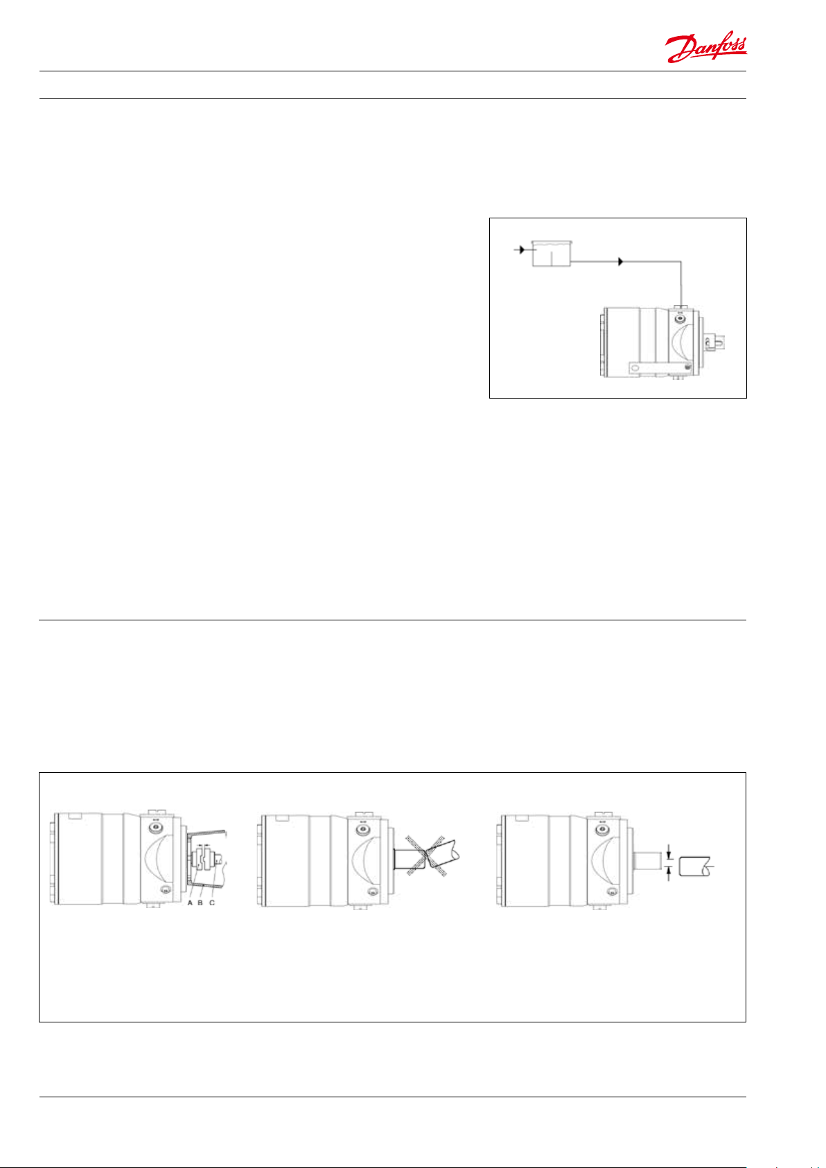
3.1 Mounting
If alternative mounting is desired, please contact
Danfoss High Pressure Pumps.
Choose proper tolerances to ensure an easy
mounting of the elastic coupling without use of
tools.
min. 3 mm
A: Elastic coupling
B: Bell housing
C: Motor shaft
Please take care to observe the recommended
length tolerances of the chosen coupling, as an
axial force on the pump shaft will prevent the
pump from generating pressure (and over time
damage the pump).
max 0.25 mm
max. 0.01 in ch
6
180R9381 | AN077186502937en-000401 | Instruction PAHT G 20-90 | 08.2020
Page 7

Instruction Pump instruction PAHT G 20-32 and PAHT G 50-90
3.2 Direction of rotation
The direction of rotation is indicated by means of
an arrow at the label of the pump.
CCW (counter clock wise)
3.3 Orientation
The pump can be mounted/orientated in any
horizontal position and it can be mounted/
orientated in the vertical position with the shaft
upwards. The pump cannot be vertically
mounted/orientated with the shaft facing
downwards.
CW (clock wise)
3.4 Protection from too high system
pressures
The valve should be placed as close to the pump
as possible.
The pump should be protected against too high
pressure by means of a pressure relief valve or a
bypass/unloading valve placed on the pressure
side.
In
Out
180R9381 | AN077186502937en-000401 | Instruction PAHT G 20-90 | 08.2020
The opening characteristics of the valve must not
result in peak pressures higher than 200 barg
(2900 psig).
In
Out
7
Page 8

Instruction Pump instruction PAHT G 20-32 and PAHT G 50-90
3.5 Connections 3.5.1 PAHT G 20-32
C
I
O
I Inlet
D Drain (vertically mount)
O Outlet
C Bleeding
XI Gauge port inlet*
XO Gauge port oulet*
Parallel key:
PAHT G 20/25/32: 8 × 7 × 32, DIN 6885
XO
C
* There are two 1/4” ports on the inlet side for
optional mounting of ie switches for low pressure
and temperature.
There is one 1/4” port on the outlet for optional
mounting of i.e. pressure transducer.
XI
XI
PAHT G 20/25/32
Outlet (O) Inlet (I) Bleeding (C) Gauge 1/4” ports
Thread, ISO
Max tighten torque
* Recommended torque values refer to steel washers containing a rubber sealing element.
3/4” BSPP with
16 mm long thread
90 Nm*
(66 lb(f)ft)
1 1/4” BSPP with
20 mm long thread
150 Nm*
(110 l b(f)f t)
M6 (width
across at = 5mm)
4 Nm*
(3 lb(f )ft)
3.5.2 PAHT G 50-90
DD
I Inlet
O Outlet
C Bleeding
D Drain (vertically mount)
XI Gauge port inlet*
XO Gauge port oulet*
PAHT G 50/63/70/80/90:
10 × 8 × 45.2 DIN 6885
XI
C
I
O
XO
C
XI
* There are two 1/4” ports on the inlet side for
optional mounting of ie switches for low pressure
and temperature.
There is one 1/4” port on the outlet for optional
mounting of i.e. pressure transducer.
1/4” BSPP with
15 mm long thread
15 Nm*
(11 lb(f )ft)
8
180R9381 | AN077186502937en-000401 | Instruction PAHT G 20-90 | 08.2020
Page 9

Instruction Pump instruction PAHT G 20-32 and PAHT G 50-90
PAHT G 50/63/70/80/90
Outlet (O) Inlet (I) Bleeding (C) Gauge 1/4” ports
Thread, ISO
Max tighten torque
* Recommended torque values refer to steel washers containing a rubber sealing element.
1” BSPP with
24 mm long thread
120 Nm*
(89 lb(f)ft)
1 ½” BSPP with
24 mm long thread
180 Nm*
(133 lb(f )ft)
M6 (width
across at = 5mm)
4 Nm*
(3 lb(f )ft)
1/4” BSPP with
15 mm long thread
15 Nm*
(11 lb(f )ft)
4. Initial
start-up
Before start-up, loosen the top bleeding plug “C”.
When water appears from the bleeding plug,
retighten the plug.
In
Out
WARNING!
Make sure that the direction of rotation of the
electric motor corresponds to the direction of
rotation of the pump.
The piping/hose between inlet lter and pump
must be ushed prior to initial start up of the
pump to ensure that impurities are removed.
C
5. Operation
5.1 Water quality
Water of drinking water quality, conrming to
the EEC directive 98/83/EC and without abrasive
sediments, demineralized water, de-ionised
water, softened water and RO water.
Please contact Danfoss High Pressure Pumps
sales organization in case of doubt.
5.2 Temperature
Fluid temperature:
Min. +3° C / 37,4° F to max. +50° C / 122° F
Ambient temperature:
Min. 0° C / 32° F to max. 50° C / 122° F
Storage temperature:
Min. -40° C / -40° F to max. +70° C / 158° F
To protect the pump from too high uid
temperature, a temperature switch of 50° C
(122° F) should be mounted on the inlet side. If
the whole pump ow is bypassed over the relief
valve, then the uid tempe-rature will go up
relatively fast.
5.3 Pressure
The inlet pressure must be between min. 0 barg
( 0 psig) and max. 6 barg (87 psig). The use of the
pump outside this range can damage the pump.
Short term inlet pressure peaks must not exceed
20 barg (290 psig). It is recommended that the
normal boost pressure is 2-6 barg (29-87 psig)
(3-7 barg [43.5-101.5 psig] abs).
If it is unknown what the peak inlet pressure can
be, then there should be a 15 barg (218 psig)
safety relief valve on the inlet side of the pump.
Max. pressure on the pump’s outlet line should
be limited at 160 barg (2320 psig) continuously.
Short-term pressure peaks (e.g. in connection
with closing of a valve) of up to 200 barg
(2900 psig) are acceptable.
It is recommended to have a check valve on the
outlet side of the pump to protect the pump
from high pressure going backwards into the
pump when it is turned o. Especially, when
using exible hose or more pumps are installed
in the same system.
180R9381 | AN077186502937en-000401 | Instruction PAHT G 20-90 | 08.2020
9
Page 10

Instruction Pump instruction PAHT G 20-32 and PAHT G 50-90
5.4 Dry running
When running, the pump must always be
connected to the water supply in order to avoid
damage if it should run dry.
In systems with water tank it is recommended to
build in a level gauge in the tank to avoid the risk
of running dry.
In systems with a boost pump, it is strongly
recommended to have a low pressure switch
mounted on the water inlet side set at minimum
2 barg (29 psig).
5.5 Disconnection
If the inlet line is disconnected from the water
supply, the pump will be emptied of water
through the disconnected inlet line. When
starting up again, follow the bleeding procedure
described under section 4: Initial start up.
5.6 Storage
When preparing the pump for long-term storage
or for temperatures below the freezing point,
ush the pump with an anti-freeze medium type
monopropylene glycol to prevent internal
corrosion or frost in the pump. If DI water with
conductivity level below 20 µS/cm is used, you
can drain the pump without adding any other
media. Just make sure that all uid is drained.
For further information on anti-freeze media,
please contact the Danfoss High Pressure Pumps
sales organization.
Recommended procedure:
5.6.1 Water hydraulic systems, water recirculated
1. Disconnect the power pack from the
system.
2. Empty the tank of water. Fill up the tank
with anti-freeze medium to a level well
above the suction line.
3. Start up the power pack and, for a couple
of minutes, in a closed loop system let the
anti-freeze medium run back to tank
through the pressure relief valve or the
bypass valve.
4. Empty the tank of the anti-freeze medium.
Empty the pump through the lower
bleeding plug.
The pump is now protected against internal
corrosion and frost.
5.6.2 Open-ended systems with water supply
from tank.
1. Empty the tank of water and empty the
pump housing through the lower bleeding
plug. When the pump is empty, retighten
the plug.
2. Through the upper bleeding plug, ll the
pump housing with anti-freeze medium.
Pour anti-freeze medium into the tank.
Connect a hose to the outlet of the pump
and lead the other end of the hose back to
tank.
3. Quickly start and stop the pump. Make
sure that the pump does not run dry.
The pump is now protected against internal
corrosion and frost.
5.6.3 Open-ended systems with direct water
supply.
1. Disconnect the water supply to the pump.
2. Through the lower bleeding plug, empty
the pump housing of water and close it
again.
3. Connect the pump to a tank of eg. 25 litre
(6 gal.) of anti-freeze additive. Connect a
hose to the inlet port of the pump and via
another hose return the ow from the
outlet port port to the tank with anti-freeze
additives.
4. Quickly start and stop the pump. Make
sure that the pump does not run dry.
The pump is now protected against internal
corrosion and frost.
6. Service The Danfoss PAHT G pumps are designed for
10
long periods of service-free operation to provide
customers with low maintenance and life cycle
costs. Provided that the pumps are installed and
operated according to Danfoss specications, the
Danfoss PAHT G pumps typically run up to 8,000
hours between service routines. However, the
service schedule for your PAHT G pump may vary
according to the application and other factors.
The life of a pump may be greatly shortened if
Danfoss recommendations concerning system
design and operation are not followed.
In our experience, poor filtration is the number
one cause of pump damage.
180R9381 | AN077186502937en-000401 | Instruction PAHT G 20-90 | 08.2020
Other factors that aect pump performance and
lifetime include:
• running the pump at speeds outside
specications
• supplying the pump with water at temperatures higher than recommended
• running the pump at inlet pressures
outside specications
• running the pump at outlet pressures
outside the specications.
Page 11

Instruction Pump instruction PAHT G 20-32 and PAHT G 50-90
7. Recommended service
intervals
7.1 General information
This guideline provides information on the
recommended service intervals for the PAHT/
PAHT G pumps. The recommendation is based
upon good engineering practice and on
experience gained from operation even under
extreme conditions.
The recommendation is for guidance only.
7.2 Inspection of pump parts
Danfoss recommends to inspect the pumps after
8,000 hours. Typical signs of wear are seen on the
contact/sliding surfaces in the pumps. If the
pumps must run for additional 8,000 hours, the
following parts will have to be inspected:
• Pistons
• Retainer plate, ball and bearing
• Valve plate
• Port plate
• Sealings
If there are any wear marks on the parts they
need to be replaced.
If service inspection due to the application is
complicated, the plant operator can decide to
extend the service interval by evaluating the
following deviations:
• Sound - does the pump have any unusual
sounds?
• Electric motor power consumption and
speed compared with measurement made
in the past.
• Pressure/ow according to measurements
made in the past?
We advise that the above mentioned parameter
during the extended service interval is inspected
for every 500-2,000 hours beyond therecommended service intervals. The pump must in any
case be inspected after maximum 16,000 hours
or 2 years.
7.3 How to inspect the pump
Service manuals are available on the internet
hpp.danfoss.com
180R9381 | AN077186502937en-000401 | Instruction PAHT G 20-90 | 08.2020
11
Page 12

Danf
already on order pro
All trademarks in this material are property of the respec
Danfoss A/S
High Pressure Pumps
DK-6430 Nordborg
Denmark
oss can accept no responsibility for possible errors in catalogues, brochures and other printed material. Danfoss reserves the right to alter its products without notice. This also applies to products
vided that such alterations can be made without subsequential changes being necessary eady agreed.
tive companies. Danfoss and the Danfoss logotype are trademarks of Danfoss A/S. All rights reserved.
© Danfoss | DCS (im) | 2020.08
180R9381 | AN077186502937en-000401
 Loading...