

Page 1
Data sheet
Data sheet
PAHT C pumps
PAHT C 2-6.3 pumps
PAHT C 2 - 6.3
ATEX PAHT C pumps
ATEX PAHT C pump
hpp.danfoss.com
hpp.danfoss.com
Page 2

Data sheet | PAHT C 2-6.3 pumps
Table of Contents
1. Introduction ....................................................................... 2
2. Benefits ...........................................................................3
3. Application examples .............................................................. 3
4. Technical data ..................................................................... 4
4.1 PAHT C 2-6.3....................................................................... 4
5. Flow............................................................................... 5
5.1 PAHT C 2-6.3 typical flow curves at max pressure (measured in water) ................5
6. Motor requirements ............................................................... 6
7. Installation ........................................................................7
7.1 Filtration .......................................................................... 7
7.2 Noise ............................................................................. 7
7.3 Open-system design ...............................................................8
7.4 Closed-system design ..............................................................9
8. Dimensions and connections ......................................................10
8.1 PAHT C 2-6.3......................................................................10
9. Service ...........................................................................11
1. Introduction
The Danfoss range of PAHT C is specifically
designed for use with technical water mixed with
chemicals or media other than water with low
viscosity.
Danfoss PAHT pumps are positive displacement
pumps, with axial pistons that move a fixed
amount of water in each cycle. Flow is proportional to the number of input shaft revolutions
(rpm). Unlike centrifugal pumps, they produce
the same flow at a given speed independently
of the discharge pressure.
The range of PAHT C pumps is based on the
standard PAHT pump series. The PAHT C pumps
are made with more resistant sealing. These
pumps are primarily used in gas turbine water
wash applications or other cleaning applications.
This data sheet is valid for PAHT C pumps both
non ATEX and ATEX certified. ATEX certified
pumps are indicated by Ex in the type
designation example PAHT C 2 Ex.
2
521B1374 | DKCFN.PD.012.4D.02 | 06.2017
Page 3
Data sheet | PAHT C 2-6.3 pumps
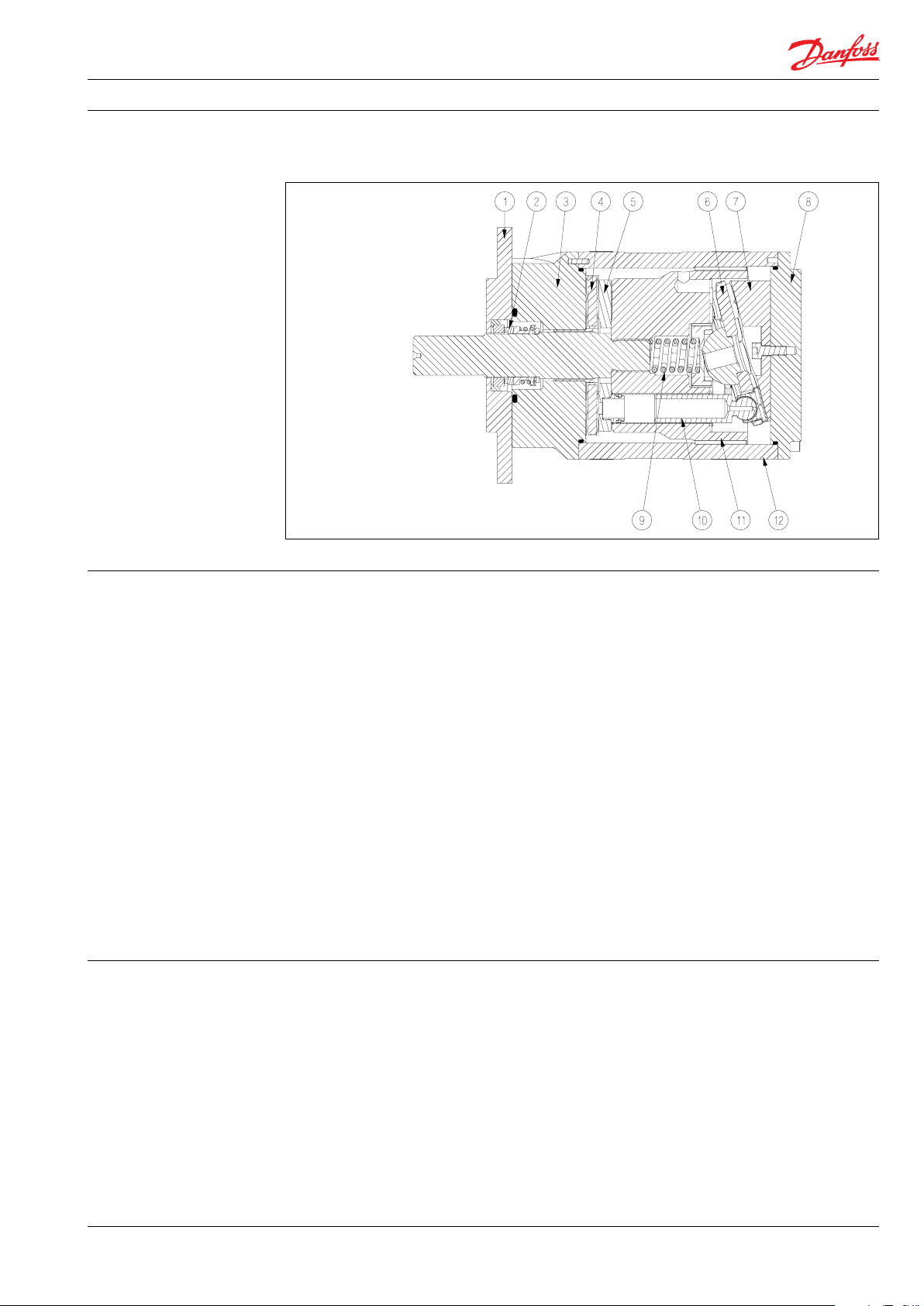
Below sectional drawing is an example of a PAHT pump.
1: Mounting flange
2: Shaft seal
3: Connecting flange
4: Port plate
5: Valve plate
6: Retainer plate
7: Swash plate
8: End cap
9: Spring
10: Pis ton
11: Cylinder barrel
12: Housing with bearing
2. Benefits • Zero risk of lubricant contamination:
- Oil lubricants are replaced with the
pumped medium, water, so there is no
contamination risk from the pump.
• Low maintenance costs:
- Efficient design and all-stainless steel
construction ensure exceptionally long
lifetime. When Danfoss specifications
are met, service intervals of up to 8,000
hours can be expected. Service is easy,
and can be carried out on site due to
the simple design and few parts.
• Low energy costs:
- The highly efficient axial piston design
provides the lowest energy consumption of any comparable pump on the
market.
• Easy installation:
- The lightest and most compact design
available.
- High resistant sealing material available
3. Application examples • High-pressure cleaning as used in the
manufacturing of flat-panel displays and
many other electronic products.
• High-pressure cleaning as used in the
manufacturing of parts for the automobile
industry.
- Pump can be installed horizontally or
vertically.
- No pulsation dampeners necessary due
to extremely low-pressure pulsation.
- Powered by electric motors or combustion engines.
- Suitable for both boosted inlet
pressure and water supply from a tank.
- No need for cooling circuits due to very
high mechanical efficiency.
• Certified quality:
- Fulfills the stringent hygiene requirements, VDI 6022, HACCP.
- Certificates:
ISO 9001, ISO 14001
ATEX available on PAHT C,
API available on request
• Reduction of NOx emissions in
gas turbines by cleaning with water wash.
521B1374 | DKCFN.PD.012.4D.02 | 06.2017
3
Page 4
Data sheet | PAHT C 2-6.3 pumps
4. Technical data 4.1 PAHT C 2-6.3
Pump size 2 3.2 4 6.3
Code number PAHT C 180B1030 180B1031 180B1032 180B1033
Code number ATEX PAHT C 18 0B1130 18 0B1131 180 B1132 18 0B1133
Housing material AISI 304 AISI 304 AISI 304 AISI 304
Sealing material FFKM FFKM FFKM FFKM
Geometric
displacement
Pressure
Min. outlet
pressure
Max. outlet
pressure
Inlet pressure,
continuous
Max. inlet
pressure, peak
Speed
Min. speed rpm 1000 1000 1000 1000
Min. speed,
continuous
Max. speed rpm 3000 3000 3000 3000
Typical flow - Flow curves available in section 5
1000 rpm at
max. pressure
1500 rpm at
max. pressure
1200 rpm at
max. pressure
1800 rpm at
max. pressure
Typical motor size
1500 rpm at
max. pressurekW50 Hz
1800 rpm at
max. pressurehp60 Hz
Torque at max.
outlet pressure
Media
temperature
Ambient
temperature
Sound pressure
3)
level
Weight
cm³/rev 2 3.2 4 6.3
in³/rev 0.12 0.20 0.24 0.38
barg 30 30 30 30
psig 435 435 435 435
barg 100 100 100 100
psig 1450 1450 1450 1450
barg 0-4 0-4 0-4 0-4
psig 0-58 0-58 0-58 0-58
1)
barg 4 4 4 4
psig 58 58 58 58
rpm 1000 1000 1000 1000
l/min 0.7 2.0 3.0 5.5
l/min 1.7 3.6 5.0 8.6
gpm 0.3 0.7 1.0 1.8
gpm 0.6 1.2 1.6 2.7
Nm 4.4 6.7 8.1 12. 4
lbf-ft 3.2 4.9 6.0 9.2
°C 2-50 2-50 2-50 2-50
°F 37-122 37-122 37-12 2 37-122
°C 0-50 0-50 0-50 0-50
°F 32-122 32-122 32-12 2 32-122
dB(A) 76 76 76 76
kg 4.4 4.4 4.4 4.4
lbs 9.7 9.7 9.7 9.7
2)
0.75 1.1 1. 5 2.2
1.0 1. 5 2.0 3.0
1)
1% per minute peak, 10% per minute during start up.
2)
Values measured in water, might differ in other media.
3)
Measurements according to EN ISO 3744: 2010 / dB(A) [L
Measured at max pressure and rpm for a motor pump unit.
4
521B1374 | DKCFN.PD.012.4D.02 | 06.2017
] values are calculated.
PA, 1m
Page 5
Data sheet | PAHT C 2-6.3 pumps
l/min
1000
1250
1500
1750
2000
2500
2250
2750
3000
20
18
16
14
12
10
8
6
4
2
0 rpm
PAHT C 2.0
PAHT C 3.2
PAHT C 4.0
PAHT C 6.3
1000
1250
1500
1750
2000
2500
2250
2750
3000
gpm
5. Flow The flow (Q
calculated with the following equation:
Q
= Q
eff
(th)
The theoretical flow can be calculated with the
following equation:
V x n
Q
=
(th)
1000
) at various pressure (p
eff
– [(Q
– Q (p
(th)
)) x (p / p
max
) can be
max
)]
max
At zero pressure the true flow equals the
theoretical flow Q
: Theoretical flow (l/min / gpm)
Q
(th)
Q (p
): Flows at max. pressure (l/min and
max
p
p: Pressure (barg / psig)
gpm), see 4.1-4.4
: Max pressure (barg / psig)
max
V: Displacement (cm
.
(th)
3
/ rev.)
n: Motor speed (rpm)
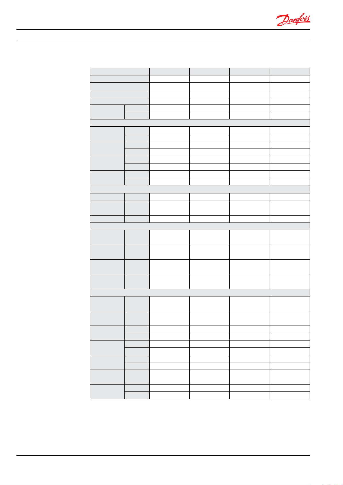
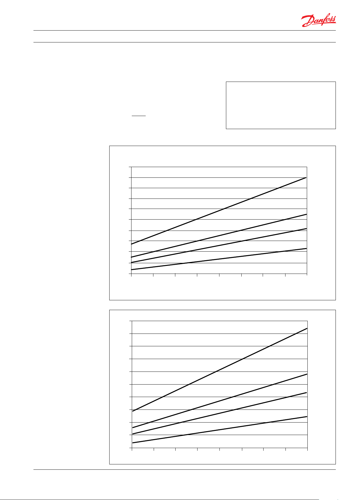
5.1 PAHT C 2-6.3 typical flow curves at max pressure (measured in water)
20
18
16
14
12
10
8
6
4
2
0 rpm
PAHT C 6.3
PAHT C 4.0
PAHT C 3.2
PAHT C 2.0
5.0
4.5
4.0
3.5
3.0
2.5
2.0
1.5
1.0
0.5
0
PAHT C 6.3
PAHT C 4.0
PAHT C 3.2
PAHT C 2.0
rpm
521B1374 | DKCFN.PD.012.4D.02 | 06.2017
5
Page 6

Data sheet | PAHT C 2-6.3 pumps
6. Motor requirements
The required motor power can be calculated by
using the following equation:
n x V x p
P =
600.000 x η
P: Power (kW)
M: Torque (Nm)
η: Mechanical efficiency
p: Pressure (barg)
n: Motor speed (rpm)
V: Displacement (cm
3
/rev.)
From the flow curves in item 5, you can determine the rpm of the pump at the desired flow.
The required torque is calculated as follows:
V x p
M =
62.8 x η
To determine the correct motor size, both the
power and torque requirement must be verified.
The mechanical efficiency of the pump, at max
pressure, is as follows:
PAHT C 2, 3.2, 4, 6.3 0.8
6
521B1374 | DKCFN.PD.012.4D.02 | 06.2017
Page 7

Data sheet | PAHT C 2-6.3 pumps
7. Installation See the figure below for instructions on how to
mount the pump and connect it to an electric
motor or combustion engine.
A CB D
A: Pump
B: Bell housing
C: Coupling
D: Motor
If alternative mounting is required, please
contact your Danfoss sales representative for
further information.
Note: Do not add any axial or radial loads to the
pump shaft.
7.1 Filtration
Proper filtration is crucial for the performance,
maintenance and warranty of your pump.
Protect your pump, and the application in which
it is installed, by always ensuring that filtration
specifications are met, and by always changing
filter cartridges according to schedule.
Since water has very low viscosity, Danfoss PAHT
pumps have been designed with very narrow
clearances in order to control internal leakage
rates and improve component performance. To
minimize wear on the pump, it is therefore
essential to filter inlet water properly.
The main filter must have a filtration efficiency
of 99.98% at 10 μm. We strongly recommend
that you always use precision depth filter
cartridges rated 10 μm abs. β
≥ 5,000.
10
Please note that we do not recommend bag
filters or string-wound filter cartridges, which
typically have only 50% filtration efficiency. This
means that out of 100,000 particles that enter
such filters, 50,000 particles pass right through
them; compare this to precision depth filters that
are 99.98% efficient, and only allow 20 of the
same 100,000 particles to pass through.
For more information on the importance of
proper filtration, including explanation of
filtration principles, definitions, and guidance on
how to select the right filter for your pump,
please consult our Filtration information and
specifications (Danfoss document number
521B10 09).
7.2 Noise
Since the pump unit is mounted on a frame, the
overall noise level can only be determined for a
complete system. To minimize vibrations and
noise throughout the system, it is therefore very
important to mount the pump unit correctly on a
frame with dampers and to use flexible hoses
rather than metal pipes where possible.
The noise level is influenced by:
• Pump speed:
High rpm makes more fluid/structureborne pulsations/vibrations than low rpm.
• Discharge pressure:
High pressures make more noise than low
pressures.
• Pump mounting:
Rigid mounting makes more noise than
flexible mounting because of the structureborne vibrations. Be sure to use dampers
when mounting.
• Connections to pump:
Pipes connected directly to the pump make
more noise than flexible hoses because of
structure-borne vibrations.
• Variable frequency drives (VFDs):
Motors regulated by VFDs can produce
more noise if the VFD does not have the
right settings.
521B1374 | DKCFN.PD.012.4D.02 | 06.2017
7
Page 8

Data sheet | PAHT C 2-6.3 pumps
7.3 Open-system design
A Inlet line:
Dimension the inlet line to obtain minimum pressure loss (large flow, minimum
pipe length, minimum number of bends/
connections, fittings with small pressure
losses and restrictions).
B Inlet filter:
Install the inlet filter (1) in front of the PAHT
pump (2). Please consult the Danfoss filter
data sheet for guidance on how to select
the right filter.
C Monitoring pressure switch:
Install the monitoring pressure switch (3)
between the filter and the pump inlet. Set
the minimum inlet pressure according to
specifications described in item 4, technical
data. The monitoring pressure switch stops
the pump if inlet pressure is lower than the
set minimum pressure.
D Monitoring temperature switch:
Install the monitoring temperature switch
(4) between the filter and the pump, on
either side of the monitoring pressure
switch. Set the temperature value according to technical data, item 4. The monitoring temperature switch stops the pump if
inlet temperature is higher than the set
value.
E Hoses:
Always use flexible hoses (5) to minimize
vibrations and noise.
F Inlet pressure:
In order to eliminate the risk of cavitation
and other pump damage, pump inlet
pressure must be maintained according to
specifications described in item 4, technical
data.
G Non-return valve (6):
Should be installed after the outlet to
prevent pump backspin, which may ruin
the pump.
H Pressure relief valve:
As the Danfoss PAHT pump begins to
create pressure and flow immediately after
start-up regardless of any counter pressure,
a pressure relief valve (7) should be
installed to prevent system damage.
I Drain:
Always install a proper drain (8) in order to
safely drain the fluid to avoid
vaporization and to ensure a safe drain,
without human contact before inspection
and/or service.
Note: If a non-return valve is mounted in the
inlet line, a low-pressure relief valve is also
recommended between the non-return valve
and the pump to protect against high-pressure
peaks.
4
2
1
PI
M
PI
System
3
5
5
8
7
6
8
521B1374 | DKCFN.PD.012.4D.02 | 06.2017
Page 9

Data sheet | PAHT C 2-6.3 pumps
7.4 Closed-system design
A Inlet line:
Dimension the inlet line to obtain minimum pressure loss (large flow, minimum
pipe length, minimum number of bends/
connections, fittings with small pressure
losses and restrictions).
B Inlet filter:
Install the filter (1) in front of the tank (2).
Please consult the Danfoss filter data sheet
for guidance on how to select the right
filter.
C Monitoring pressure switch:
Install the monitoring pressure switch (3) in
front of the filter (1). Set the maximum inlet
pressure to 2 barg (29.0 psig). The monitoring pressure switch will stop the pump (5) if
inlet pressure is higher than 2 barg (29.0
psig), indicating that the filter element
must be changed.
D Monitoring temperature switch:
Install the monitoring temperature switch
(4) in the tank. Set the temperature value
according to technical data, item 4. The
monitoring temperature stops the pump if
inlet temperature is higher than the set
value.
E Hoses:
Always use flexible hoses (6) to minimize
vibrations and noise.
F Inlet pressure:
In order to eliminate the risk of cavitation
and other pump damage, pump inlet
pressure must be maintained according to
specifications described in item 4, technical
data.
G Non-return valve (7):
Should be installed after the outlet to
prevent pump backspin, which may ruin
the pump.
H Pressure relief valve:
As the Danfoss PAHT pump begins to
create pressure and flow immediately after
start-up regardless of any counter pressure,
a pressure relief valve (8) should be
installed to prevent system damage.
I System water filling:
To ensure proper filtration of new water
(10) supplied to the system, always use the
filling valve (9).
J Minimum level switch:
Install the minimum level switch (11) above
the outlet of the reservoir. The level switch
must stop the pump if the water in the
reservoir is below the switch, which
indicates that the reservoir is empty.
K Drain:
Always install a proper drain (12) in order
to safely drain the fluid to avoid
vaporization and to ensure a safe drain,
without human contact before inspection
and/or service.
2
11
Reservoir
4
5
M
6 6 7
PI
PI
System
12
9
1
3
10
8
521B1374 | DKCFN.PD.012.4D.02 | 06.2017
9
Page 10

Data sheet | PAHT C 2-6.3 pumps
8. Dimensions and
connections
8.1 PAHT C 2-6.3
10
521B1374 | DKCFN.PD.012.4D.02 | 06.2017
Page 11

Data sheet | PAHT C 2-6.3 pumps
9. Service Danfoss PAHT C pumps are designed for long
periods of service-free operation to ensure low
maintenance and life cycle costs. Provided that
the pump is installed and operated according to
Danfoss specifications, Danfoss PAHT C pumps
typically run 8,000 hours between service
(Validated in water). However, the service
schedule for your PAHT C pump may vary according to the application and other factors. Some
chemicals might change the surface tension
which the pumps are relying on and therefore
decrease the service intervals.
The life of a pump may be greatly shortened if
Danfoss recommendations concerning system
design and operation are not followed.
In our experience, poor filtration is the number
one cause of pump damage.
Other factors that affect the pump performance
and lifetime include:
- Running the pump speeds outside
specifications
- Supplying the pump with temperatures
higher than recommended
- Running the pump at inlet pressures
outside specifications
- Running the pump at outlet pressures
outside the specifications
We recommend that you inspect your pump
after 8,000 hours of operation even if it is
running without any noticeable problems.
Replace any worn parts if necessary, including
pistons and shaft seals, to keep your pump
running efficiently and to prevent breakdown. If
worn parts are not replaced, then our guidelines
recommend more frequent inspection.
Make sure to install a proper drain to avoid any
spill of fluid into the surroundings, drain the
whole pump before servicing and wear necessary safety equipment.
Read the Service Instruction before servicing the
pump.
521B1374 | DKCFN.PD.012.4D.02 | 06.2017
11
Page 12

Danfoss A/S
High Pressure Pumps
Nordborgvej 81
DK-6430 Nordborg
Denmark
© Danfoss | DCS (im) | 2017.06
521B1374 | DKCFN.PD.012.4D.02 | 12
 Loading...