

Page 1
Service guide
PAHT / PAHT G pumps
PAHT 50-90 / PAHT G 50-90
Disassembling and assembling
hpp.danfoss.com
Page 2
Service guide | Disassembling and assembling PAHT and PAHT G 50-90
Table of Contents 1. Introduction .............................................................................................................................................................. 2
2. Disassembling the pump ..................................................................................................................................... 2
3. Inspection .................................................................................................................................................................. 9
4. Assembly ..................................................................................................................................................................10
5. Spare parts list for PAHT 50-90 .........................................................................................................................18
6. Exploded view for PAHT 50-90 .........................................................................................................................19
7. Spare parts list for PAHT G 50-90 .....................................................................................................................20
8. Exploded view for PAHT G 50-90 .....................................................................................................................21
9. Tool sets ....................................................................................................................................................................22
1. Introduction
NOTE: If the pump is disassembled within the warranty period, the pump is no longer covered
by the warranty.
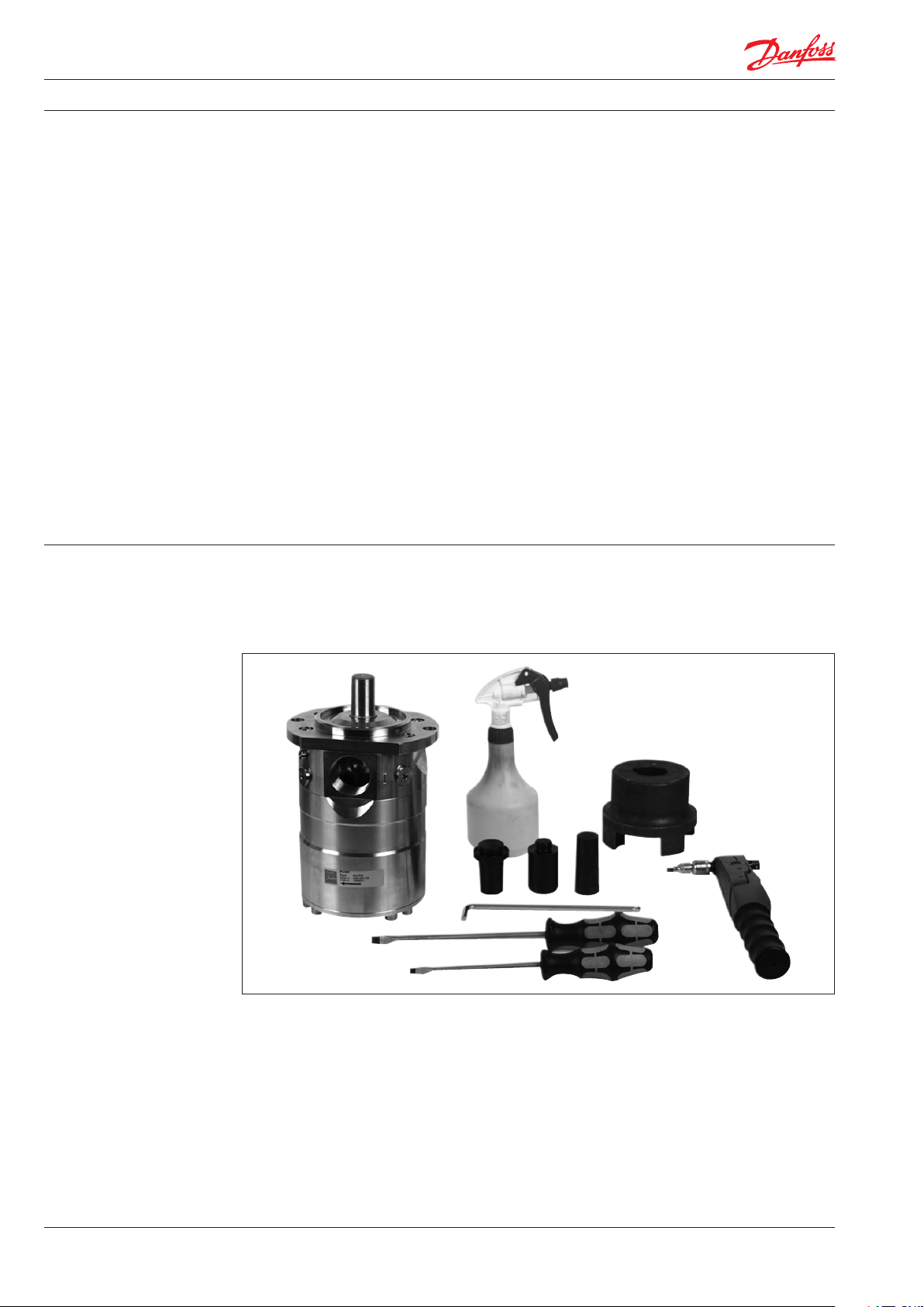
Tools required for dismantling the pump
2
180R9172 | 521B1092 | DKCFN.PI.012.D4.02 | 06.2017
Page 3
Service guide | Disassembling and assembling PAHT and PAHT G 50-90
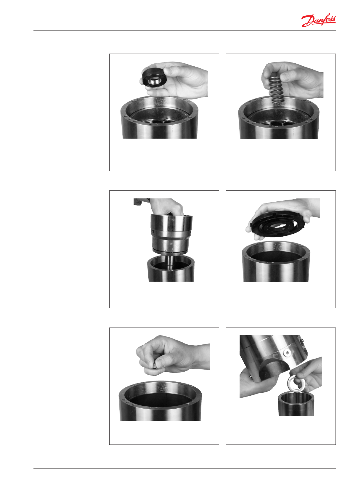
2. Disassembling the
pump
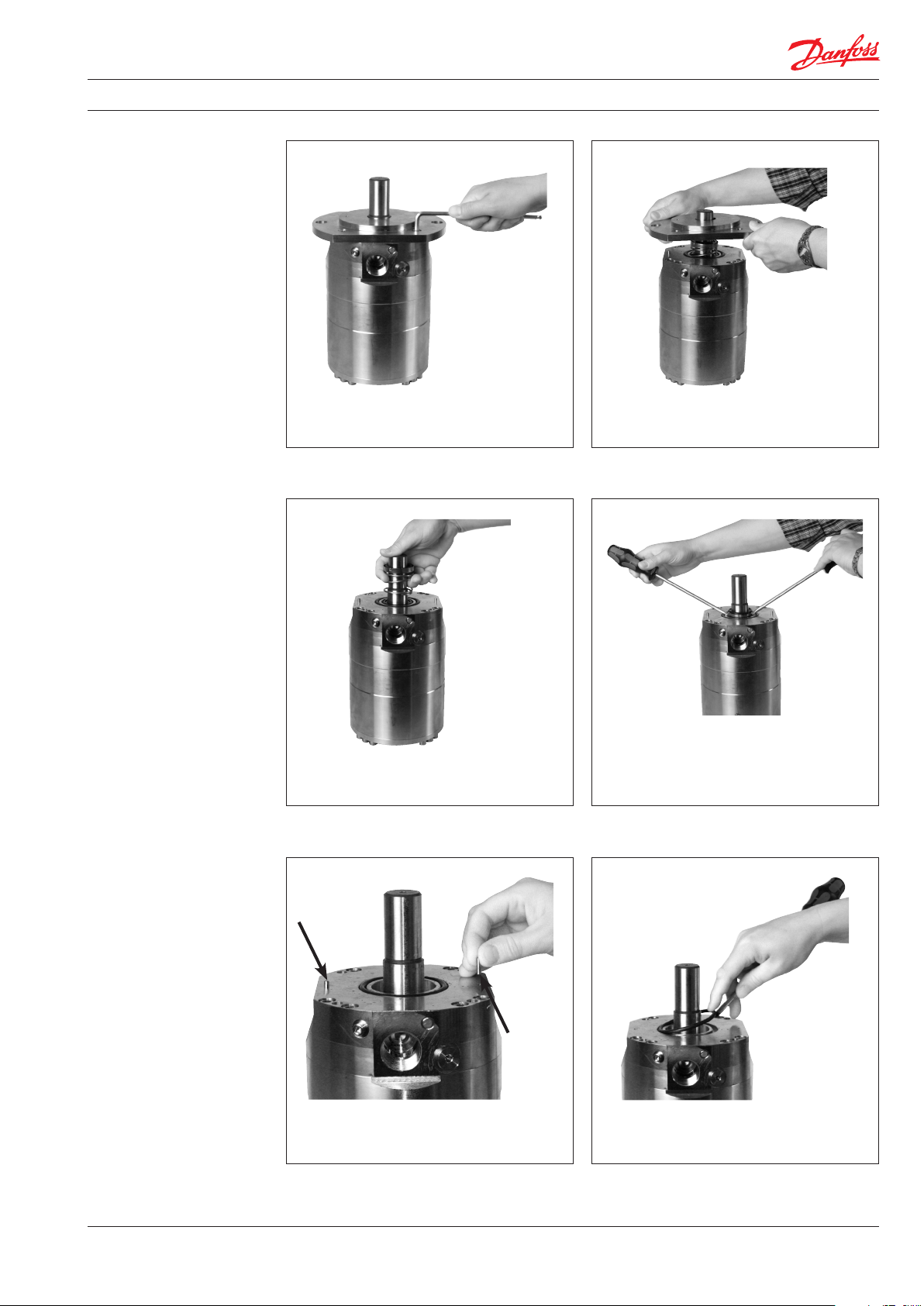
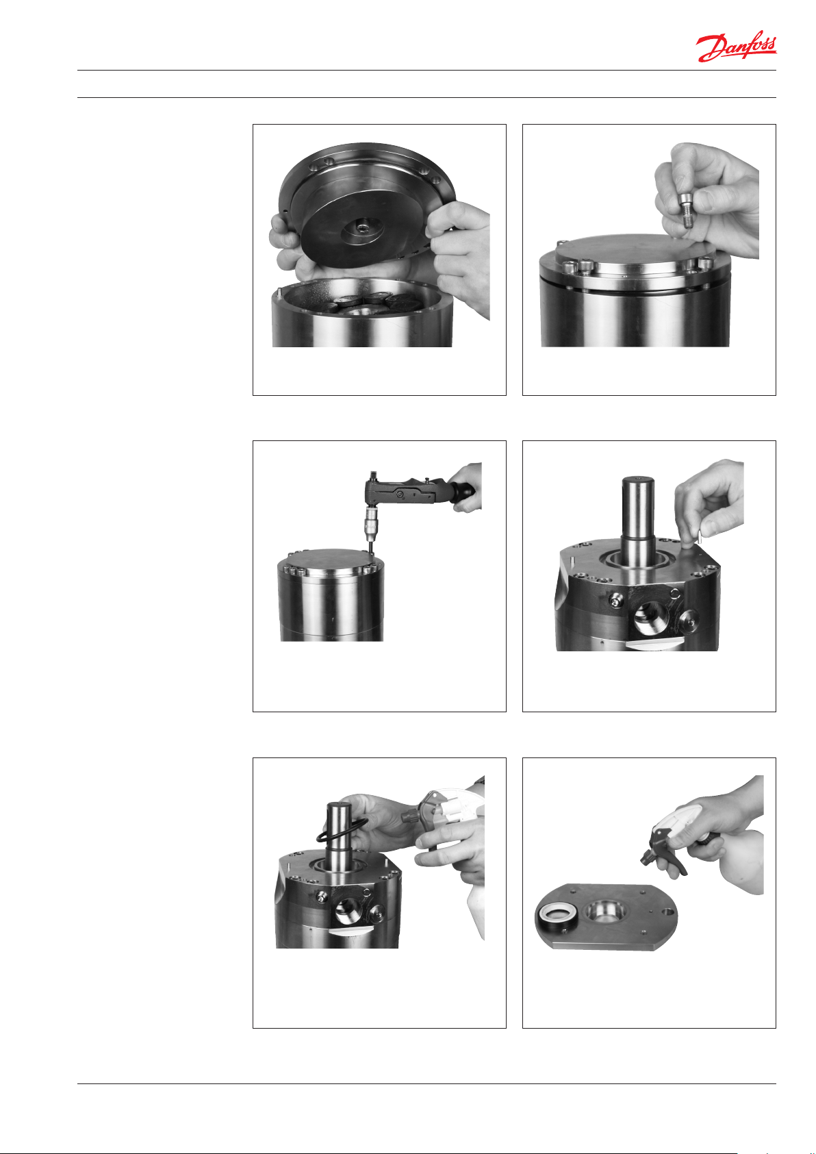
2. Remove mounting ange.1. Loosen and remove 4 screws.
4. Remove shaft sealing.
Caution: Avoid to scratch the sealing
3. Remove spring.
surface on the shaft.
5. Remove 2 guide pins. 6. Remove O-ring.
180R9172 | 521B1092 | DKCFN.PI.012.D4.02 | 06.2017
3
Page 4
Service guide | Disassembling and assembling PAHT and PAHT G 50-90
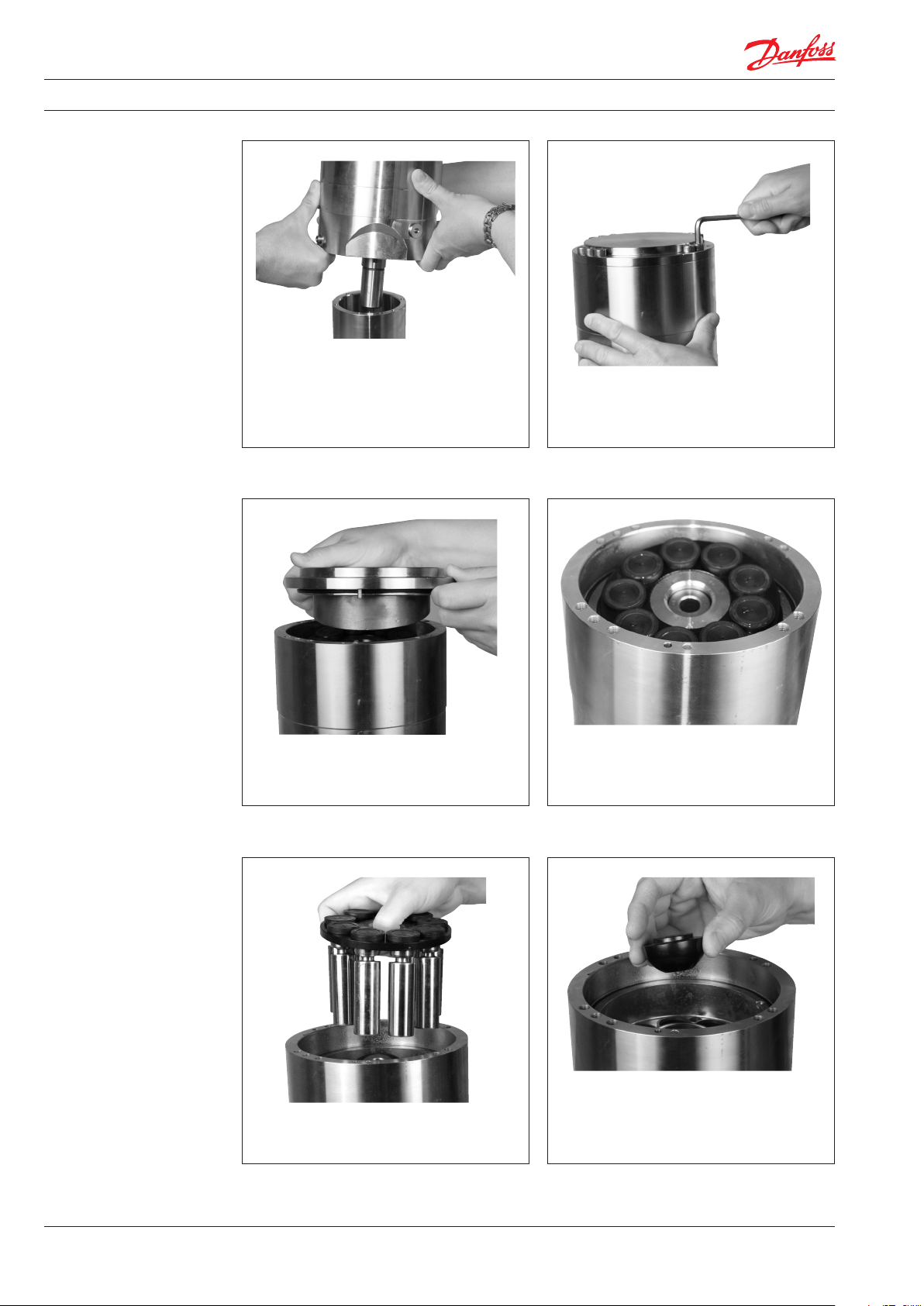
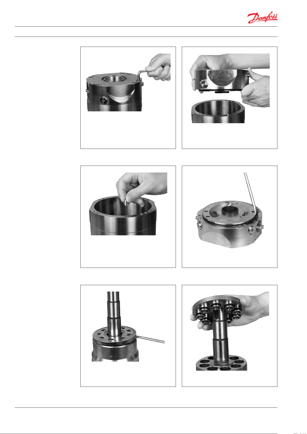
7. Turn pump upside down. 8. Loosen and remove 10 screws.
9. Remove cover.
11. Remove retainer ball10. Remove pistons and retainer plate.
4
180R9172 | 521B1092 | DKCFN.PI.012.D4.02 | 06.2017
Page 5
Service guide | Disassembling and assembling PAHT and PAHT G 50-90
13. Remove spring12. Remove retainer
14. Remove cylinder barrel. 15. Remove port plate.
17. Turn pump upside down and remove 2
washers.16. Remove 1 guide pin.
180R9172 | 521B1092 | DKCFN.PI.012.D4.02 | 06.2017
5
Page 6
Service guide | Disassembling and assembling PAHT and PAHT G 50-90
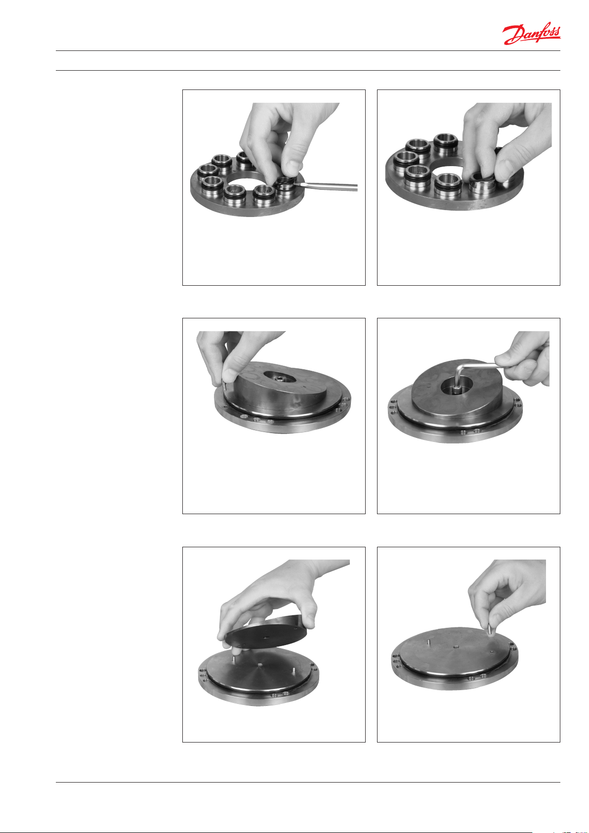
18. Loosen and remove 6 screws. 19. Remove port ange.
21. Remove O-ring from port ange.20. Remove 1 guide pin.
22. Loosen thrust plate from cylinder barrel. 23. Remove thrust plate.
6
180R9172 | 521B1092 | DKCFN.PI.012.D4.02 | 06.2017
Page 7
Service guide | Disassembling and assembling PAHT and PAHT G 50-90
25. Remove backup rings from thrust plate.24. Remove O-rings from thrust plate.
27. Loosen and remove screw from swash
plate.26. Remove 1 guide pin from end cover plate.
29. Remove 2 guide pins from end cover plate.28. Remove swash plate.
180R9172 | 521B1092 | DKCFN.PI.012.D4.02 | 06.2017
7
Page 8
Service guide | Disassembling and assembling PAHT and PAHT G 50-90
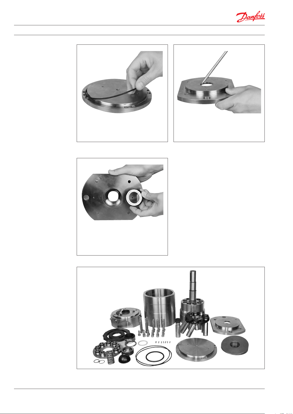
30. Remove O-ring from end cover plate.
Pump disassembled
31. Remove shaft sealing from mounting
ange.
8
180R9172 | 521B1092 | DKCFN.PI.012.D4.02 | 06.2017
Page 9

Service guide | Disassembling and assembling PAHT and PAHT G 50-90
3. Inspection
Valve and thrust plate
Valve and thrust plate
2. Hold a ruler against surface of plate and
check tightness against a light source.
3. Check that both O-rings and back-up rings
1. Neither valve plate nor thrust plate must
show any sign of wear.
are not broken and do not show severe
wear.
Swash plate Pistons
4. Check that surface of swash plate is
smooth and without any large
scratches (depth more than 0.1 mm).
7. Hold a ruler against surfaces of piston
shoes to check that the surfaces are even
and smooth and without any scratches.
It is acceptable that the (black) treated
surfaces of the pistons are partly worn.
5. Play in ball and socket joint must not
exceed 0.1 mm.
6. Thickness of piston shoes must be at least
4.4 mm.
8. Check bushes in cylinderbarrel for wear
and scratches.
9. Check main bearing for wear and scratches.
180R9172 | 521B1092 | DKCFN.PI.012.D4.02 | 06.2017
9
Page 10

Service guide | Disassembling and assembling PAHT and PAHT G 50-90
4. Assembly
WARNING:
Do not use silicone when assembling the
pump. Do not reuse disassembled O-rings;
they might be damaged. Always use new
O-rings.
1. Lubrication:
• To prevent seizing-up, lubricate all
threads with PTFE lubrication type.
• O-rings inside pump may be lubricated
only with clean ltered water.
• O-rings for port ange, mounting ange
and ushing valve must be lubricated.
• It is important to lubricate ALL parts to
be assembled with clean ltered water
(Especially all PEEK parts).
Important:
It is essential that the pump is serviced in
conditions of absolute cleanliness. All parts
must be absolute clean before mounting.
1. Tools required for assembly of the pump.
2. Parts needed for assembly of the pump.
4. Mount O-ring in port ange.3. Mount 1 guide pin in housing.
10
180R9172 | 521B1092 | DKCFN.PI.012.D4.02 | 06.2017
Page 11

Service guide | Disassembling and assembling PAHT and PAHT G 50-90
5. Mount port ange on housing. Use pin as
guide.
6. Mount 6 screws (M8x55).
8. Turn pump upside down.7. Tighten screws to 30Nm.
9. Mount 1 guide pin inside the housing on
the back side of the port plate.
180R9172 | 521B1092 | DKCFN.PI.012.D4.02 | 06.2017
10. Mount port plate. Be aware of orientation/
guide pin.
11
Page 12

Service guide | Disassembling and assembling PAHT and PAHT G 50-90
12. Mount O-rings on the thrust plate.11. Mount backup rings on the thrust plate.
13. Spray with water on cylinder barrel and
thrust plate.
14. Mount thrust plate on cylinder barrel.
15. Press thrust plate into cylinder barrel. 16. Mount cylinder barrel in housing.
12
180R9172 | 521B1092 | DKCFN.PI.012.D4.02 | 06.2017
Page 13

Service guide | Disassembling and assembling PAHT and PAHT G 50-90
18. Mount retainer on top of the spring.17. Mount spring.
20. Place retainer plate on top of retainer ball.19. Spray with water and mount retainer ball.
22. Spray with water and mount O-ring on
end cover.21. Spray with water and mount pistons.
180R9172 | 521B1092 | DKCFN.PI.012.D4.02 | 06.2017
13
Page 14

Service guide | Disassembling and assembling PAHT and PAHT G 50-90
24. Mount swash plate.23. Mount 2 guide pins on endcover.
26. Tighten screw to 30Nm.25. Mount screw (M8x20).
27. Mount 1 guide pin on housing. 28. Spray piston shoes with water.
14
180R9172 | 521B1092 | DKCFN.PI.012.D4.02 | 06.2017
Page 15
Service guide | Disassembling and assembling PAHT and PAHT G 50-90
29. Mount endcover on the housing. 30. Mount 10 screws (M8x20).
31. Tighten 10 screws to 30Nm.
33. Spray with water and mount O-ring.
32. Turn pump upside down and mount 2
guide pins.
34. Spray shaft sealing with water before
mounting.
180R9172 | 521B1092 | DKCFN.PI.012.D4.02 | 06.2017
15
Page 16

Service guide | Disassembling and assembling PAHT and PAHT G 50-90
36. Use tool and press shaft sealing into place.35. Mount shaft sealing.
38. Mount metal ring.37. Mount transparent ring.
39. Mount spring. 40. Mount special tool on shaft.
16
180R9172 | 521B1092 | DKCFN.PI.012.D4.02 | 06.2017
Page 17

Service guide | Disassembling and assembling PAHT and PAHT G 50-90
41. Spray with water.
43. Mount mounting ange.
42. Mount sealing (smallest diameter pointing
down).
44. Mount 4 screws.
45. Tighten screws to 30Nm. 46. Finished.
180R9172 | 521B1092 | DKCFN.PI.012.D4.02 | 06.2017
17
Page 18

Service guide | Disassembling and assembling PAHT and PAHT G 50-90
5. Spare parts list for
PAHT 50-90
Pos. Qnt. Designation Material
1 1 Housing AISI 316
2 2 Pin ø4 x 14 AISI 304 x
5 10 Screw M8 x 16 AISI 304 x
9 1 O-ring ø135 x 3 NBR x
11 1 End cover CW AISI 316
31 1 Swash plate AISI 431 x x x x x
32 1 Screw M8 x 20 AISI 304 x x x x x
34 2 Pin ø4 x 14 AISI 304 x x x x x
61 1 Cylinder barrel AISI 431 x
62 1 Spring 1.4462 x
64 1 Retainer ball AISI 431 x
65 1 Retainer plate AISI 304 x
66 9 Piston AISI 431/ PEEK x
67 1 Key 8 x 7 x 32 AISI 316Ti x
70 1 Washer Polypropylen x
71 1 Retainer AISI 304 / PEEK x
91 1 Port plate AISI 304 / PEEK x x
92 1 Valve plate AISI 431 x x
93 9 Back up ring PTFE x x
94 9 O-ring ø18,3 x 2,4 NBR x x
121 1 Port ange AISI 316
122 1 O-ring ø135 x 3 NBR x
123 1 O-ring Ø65 x 5 NBR x
124 1 Shaft sealing AISI 304 / NBR x
125 1 End cover AISI 316
126 1 Pin ø6 x 10 AISI 304 x x
127 6 Screw M8 x 70 AISI 304 x
128 4 Screw M8 x 55 AISI 304 x
1 Service instruction x x x x x x x x x x
180B4196 - Seal set
(PAHT 50-90)
180B4195 - Cylinder barrel set
(PAHT 50-90)
180B4192 - Valve plate set
(PAHT 50-70)
180B4193 - Valve plate set
(PAH T 80-90)
180B4194 - Piston set
(PAHT 50-90)
180B4252 - Swash plate set
(PAHT 50)
180B4255 - Swash plate set
(PAH T 63)
180B4258 - Swash plate set
(PAH T 70)
180B4253 - Swash plate set
(PAH T 80)
180B4256 - Swash plate set
(PAH T 90)
18
180R9172 | 521B1092 | DKCFN.PI.012.D4.02 | 06.2017
Page 19

Service guide | Disassembling and assembling PAHT and PAHT G 50-90
6. Exploded view
for PAHT 50-90
180R9172 | 521B1092 | DKCFN.PI.012.D4.02 | 06.2017
19
Page 20

Service guide | Disassembling and assembling PAHT and PAHT G 50-90
7. Spare parts list for
PAHT G 50-90
Pos. Qnt. Designation Material
1 1 Housing AISI 316
2 2 Pin ø4 x 14 AISI 304 x
5 10 Screw M8 x 16 AISI 304 x
9 1 O-ring ø135 x 3 NBR x
11 1 End cover CW AISI 316
31 1 Swash plate AISI 431 x x x x x
32 1 Screw M8 x 20 AISI 304 x x x x x
34 2 Pin ø4 x 14 AISI 304 x x x x x
61 1 Cylinder barrel AISI 431 x
62 1 Spring 1.4462 x
64 1 Retainer ball AISI 431 x
65 1 Retainer plate AISI 304 x
66 9 Piston AISI 431 / PEEK x
67 1 Key 8 x 7 x 32 AISI 316Ti x
70 1 Washer Polypropylen x
71 1 Retainer AISI 304 / PEEK x
91 1 Port plate AISI 304 / PEEK x x
92 1 Valve plate AISI 431 x x
93 9 Back up ring PTFE x x
94 9 O-ring ø18,3 x 2,4 NBR x x
121 1 Port ange AISI 316
122 1 O-ring ø135 x 3 NBR x
123 1 O-ring Ø65 x 5 NBR x
124 1 Shaft sealing AISI 304 / NBR x
125 1 End cover AISI 316
126 1 Pin ø6 x 10 AISI 304 x x
127 6 Screw M8 x 70 AISI 304 x
128 4 Screw M8 x 55 AISI 304 x
1 Service instruction x x x x x x x x x x
180B4341 - Seal set
(PAHT G 50-90)
180B4339 - Cylinder barrel set
(PAHT G 50-90)
180B4340 - Valve plate set
(PAHT G 50-70)
180B4344 - Valve plate set
(PAHT G 80-90)
180B4343 - Piston set
(PAHT G 50-90)
180B4326 - Swash plate set
(PAHT G 50)
180B4327 - Swash plate set
(PAHT G 63)
180B4328 - Swash plate set
(PAHT G 70)
180B4329 - Swash plate set
(PAHT G 80)
180B4330 - Swash plate set
(PAHT G 90)
20
180R9172 | 521B1092 | DKCFN.PI.012.D4.02 | 06.2017
Page 21

Service guide | Disassembling and assembling PAHT and PAHT G 50-90
8. Exploded view
for PAHT G 50-90
180R9172 | 521B1092 | DKCFN.PI.012.D4.02 | 06.2017
21
Page 22

Service guide | Disassembling and assembling PAHT and PAHT G 50-90
9. Tool sets
Qnt. Designation
1 Shaft bush, topedo x
1 Press tool 1 x
1 Press tool 2 x
180Z0237 - Tool set
(PAH / PAHT / PAHT G 50-90)
22
180R9172 | 521B1092 | DKCFN.PI.012.D4.02 | 06.2017
Page 23

Service guide | Disassembling and assembling PAHT and PAHT G 50-90
180R9172 | 521B1092 | DKCFN.PI.012.D4.02 | 06.2017
23
Page 24

Danfoss A/S
Nordborgvej 81
DK-6430 Nordborg
Denmark
© Danfoss | DCS (im) | 2017.06
180R9172 | 521B1092 | DKCFN.PI.012.D4.02 | 24
 Loading...