

Page 1
Data sheet
Data sheet
PAH pumps
PAH 2/4/6.3, PAH 10/12.5,
PAH 2/4/6.3, PAH 10/12.5,
PAH 20/25/32 and
PAH 20/25/32 and
PAH 50/63/70/80/100
PAH 50/63/70/80/100 pumps
danfoss.high-pressurepumps.com
hpp.danfoss.com
Page 2

Data sheet PAH 2/4/6.3, PAH 10/12.5, PAH 20/25/32 and PAH 50/63/70/80/100 pumps
Table of Contents
Contents
1. Introduction ............................................................................2
2. Benets.................................................................................3
3. Application examples ...................................................................3
4. Technical data ..........................................................................4
4.1 PAH 2-12.5 ..............................................................................4
4.2 PAH 20-32 ..............................................................................5
4.3 PAH 50-100 .............................................................................6
5. Flow ....................................................................................7
5.1 PAH 2-6.3 typical ow curves at max pressure ...........................................7
5.2 PAH 10-12.5 typical ow curves at max pressure..........................................8
5.3 PAH 20-32 typical ow curves at max pressure ...........................................9
5.4 PAH 50-100 typical ow curves at max pressure .........................................10
6. Motor requirements....................................................................11
7. Installation.............................................................................12
7.1 Filtration ..............................................................................12
7.2 Noise ..................................................................................12
7.3 Open-system design ...................................................................13
7.4 Closed-system design .................................................................14
8. Dimensions and connections...........................................................15
8.1 PAH 2-6.3 ..............................................................................15
8.2 PAH 10-12.5 ............................................................................16
8.3 PAH 20-25 .............................................................................17
8.4 PAH 50-100 ............................................................................18
1. Introduction
9. Service.................................................................................19
The data sheet is valid for PAH pumps both non
ATEX and ATEX certied. The ATEX certied
versions are indicated with Ex in the designation.
The Danfoss range of PAH high-pressure pumps
is designed to supply water ow under highpressure for a varity of tap water applications.
Danfoss PAH pumps are positive displacement
pumps, with axial pistons that move a xed
amount of water in each cycle. Flow is proportional to the number of input shaft revolutions
(rpm). Unlike centrifugal pumps, they produce
the same ow at a given speed no matter what
the discharge pressure.
All components are designed to provide long
service life with a constantly high eciency and
minimum service required.
In the following all pumps are named PAH.
2 | AI073186502976en-001801
© Danfoss | DCS (im) | 2021.11
Page 3
Data sheet PAH 2/4/6.3, PAH 10/12.5, PAH 20/25/32 and PAH 50/63/70/80/100 pumps
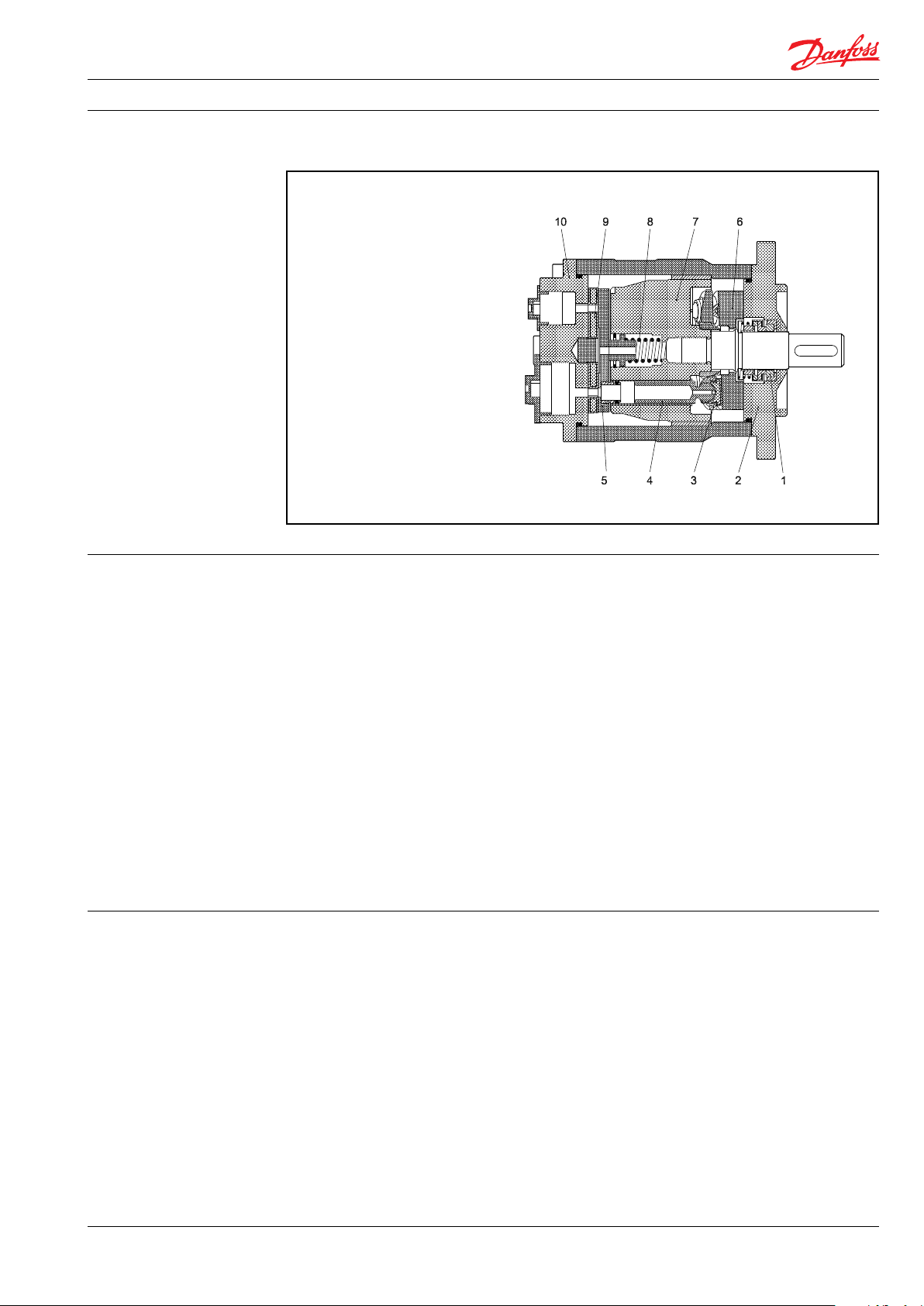
Below sectional drawing is an example of a PAH pump.
1: Shaft sealing
2: Mounting ange/
housing with bearing
3: Retaining ring
4: Piston/shoe
5: Valve trust plate
6: Swash plate
7: Cylinder barrel8:
8: Spring
9: Port plate
10: Connecting ange
2. Benets • Zero risk of lubricant contamination:
- Oil lubricants are replaced with the
pumped medium, water, so there is no
contamination risk from the pump.
• Low maintenance costs:
- Ecient design and all-stainless steel
construction ensure exceptionally long
lifetime. When Danfoss specications
are met, service intervals of up to 8,000
hours can be expected. Service is easy,
and can be carried out on site due to
the simple design and few parts.
• Low energy costs:
- The highly ecient axial piston design
provides the lowest energy consumption of any comparable pump on the
market.
• Easy installation:
- The lightest and most compact design
available.
3. Application examples • Stationary and mobile hydraulic systems
• High-pressure systems
• Fire ghting
- Pump can be installed horizontally or
vertically.
- No pulsation dampeners necessary due
to extremely low-pressure pulsation.
- Powered by electric motors or combustion engines.
- Suitable for both boosted inlet
pressure and water supply from a tank.
- No need for cooling circuits due to very
high mechanical eciency.
• Certied quality:
Certicates:
ISO 9001, ISO 14001, ITF 16949
ATEX available on request
ABS and DNV GL certications on
request
• Flushing and cleaning processes
• Humidication systems
© Danfoss | DCS (im) | 2021.11© Danfoss | DCS (im) | 2021.11
AI073186502976en-001801 | 3
Page 4
Data sheet PAH 2/4/6.3, PAH 10/12.5, PAH 20/25/32 and PAH 50/63/70/80/100 pumps
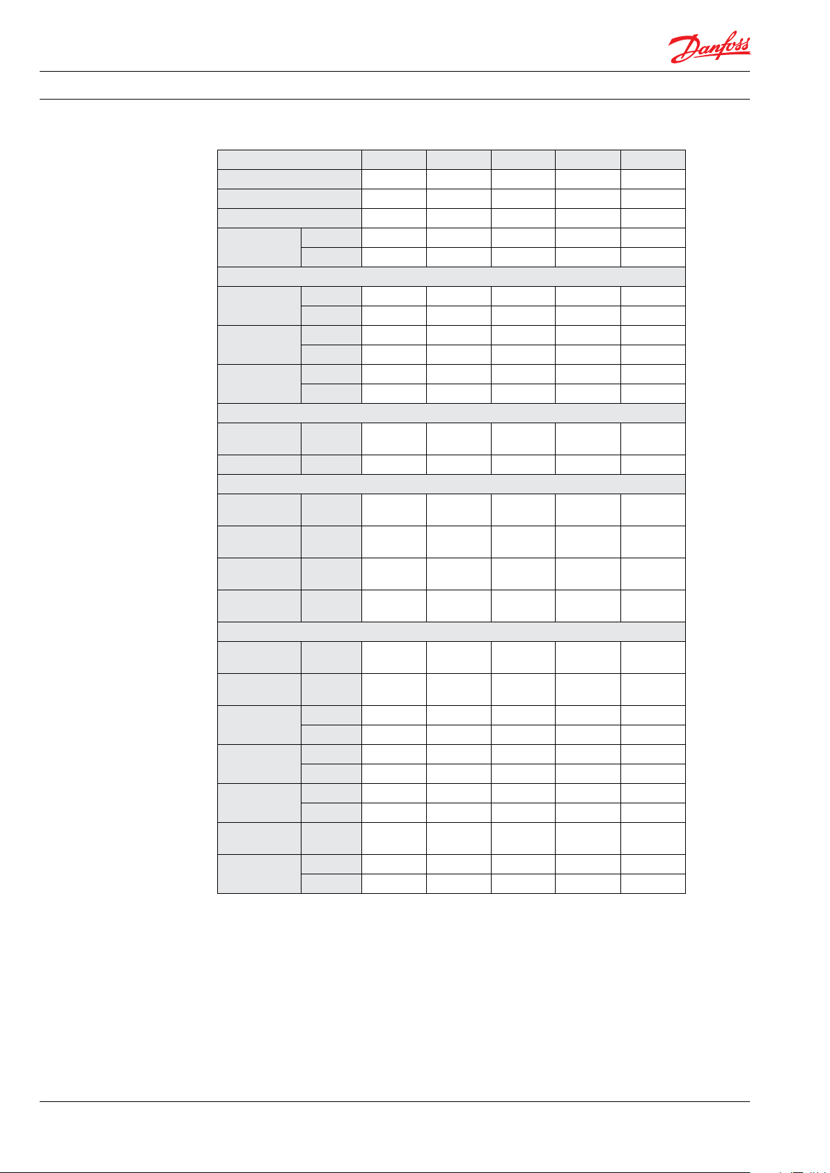
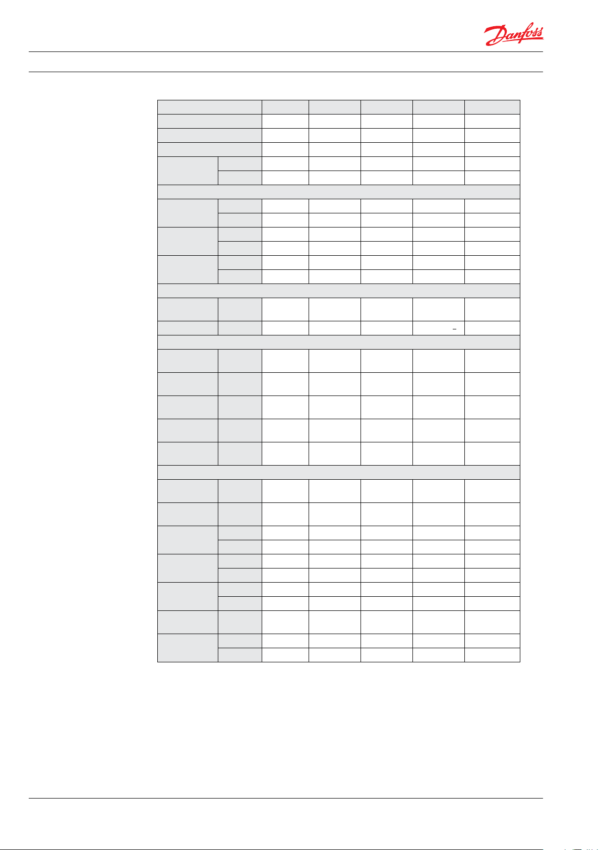
4. Technical data 4.1 PAH 2-12.5
Pump size 2 4 6.3 10 12 .5
Code number 180B0 024 18 0B0022 180B0023 180B0008 180B0007
Code number ATEX
Housing material AISI 304 AISI 304 AISI 304 AISI 304 AISI 304
Geometric
displacement
Pressure
Min. outlet
pressure
Max. outlet
pressure
Inlet pressure,
continuous
Speed
Min. speed,
continuous
Max. speed rpm 1800 1800 1800 1800 1800
Typical ow - Flow curves available in section 5
1000 rpm at
max. pressure
1500 rpm at
max. pressure
1200 rpm at
max. pressure
1800 rpm at
max. pressure
Typical motor size
1500 rpm at
max. pressure
1800 rpm at
max. pressure
Torque at max.
spec.
Media
temperature
Ambient
temperature
Sound
pressure level
Weight kg 4.4 4.4 4.4 7.7 7.7
For certied pumps specications on inlet and outlet pressure is stated on the 3.1 inspection certicate and may
vary from generic specications stated above.
2)
180B 6124 180B 6122 180B612 3 180B6108 180B6107
cm³/rev 2 4 6.3 10 12 .5
in³/rev 0.12 0.24 0.38 0.60 0.75
barg 30 30 30 30 30
psig 435 435 435 435 435
barg 140 140 140 160 160
psig 2030 2030 2030 2320 2320
barg 0-4 0-4 0-4 0-4 0-4
psig 0-58 0-58 0-58 0-58 0-58
rpm 700 700 700 700 700
l/min 1.0 3.2 5.6 8.4 11.0
l/min 2.0 5.2 8.7 13.4 17.2
gpm 0.4 1. 0 1.8 2.7 3.5
gpm 0.7 1.7 2.8 4.3 5.5
kW
hp
0.9 1.7 2.6 4.5 5.6
1.5 2.7 4.2 7.3 9.0
Nm 5.9 10.9 16.7 29.0 35.8
lbf-ft 4.4 8.0 12. 3 21.4 26.4
°C 2-50 2-50 2-50 2-50 2-50
°F 36 -122 36 -122 36 -122 3 6-122 36 -122
°C 0-50 0-50 0-50 0-50 0-50
°F 32-12 2 32-12 2 32-122 32-122 32-12 2
dB(A) 76 76 76 75 75
1)
lbs 9.7 9.7 9.7 17.0 17.0
4 | AI073186502976en-001801
1)
Measurements according to EN ISO 3744: 2010 / dB(A) [L
Measured at max pressure and rpm for a motor pump unit.
2)
Category 2, Zone 1 or Category 3, Zone 2.
] values are calculated.
PA, 1m
© Danfoss | DCS (im) | 2021.11
Page 5
Data sheet PAH 2/4/6.3, PAH 10/12.5, PAH 20/25/32 and PAH 50/63/70/80/100 pumps
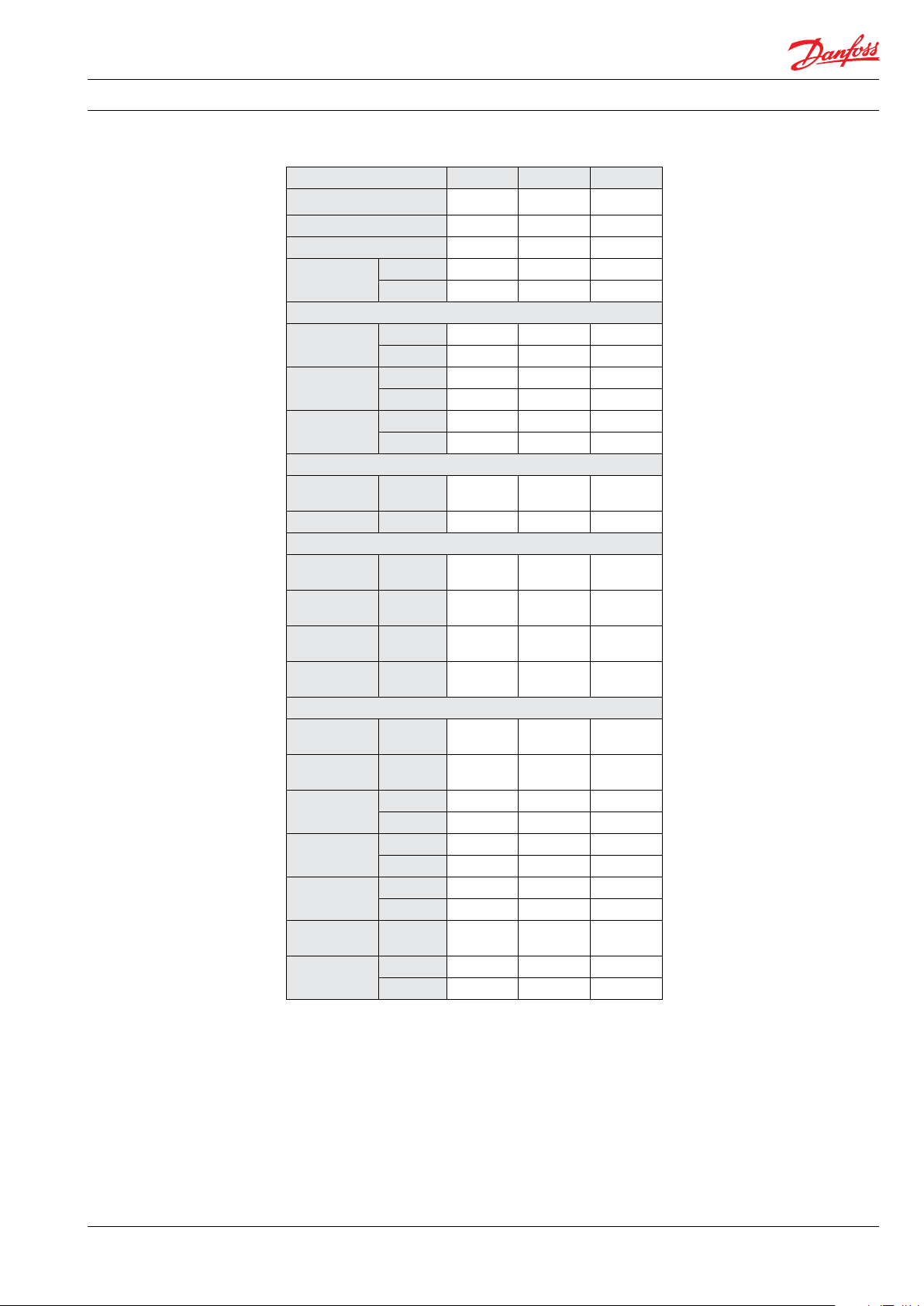
4.2 PAH 20-32
Pump size 20 25 32
Code number 18 0B0079 180 B0036 180 B0037
Code number ATEX
3)
Housing material AISI 304 AISI 304 AISI 304
Geometric
displacement
cm³/rev 20 25 32
in³/rev 1.22 1.53 1.95
Pressure
Min. outlet
pressure
Max. outlet
pressure
Inlet pressure,
continuous
barg 30 30 30
psig 435 435 435
barg 80 160 160
psig 1160 2321 2321
barg 0-4 0-4 0-4
1)
psig 0-58 0-58 0-58
Speed
Min. speed,
continuous
rpm 700 700 700
Max. speed rpm 1800 1800 1800
Typical ow - Flow curves available in section 5
1000 rpm at
max pressure
1500 rpm at
max pressure
1200 rpm at
max. pressure
1800 rpm at
max. pressure
l/min 18.8 22.5 29.7
l/min 28.9 35.2 45.9
gpm 5.9 7. 2 9.4
gpm 9.1 11.1 14.5
Typical motor size
1500 rpm at
kW
max. pressure
1800 rpm at
hp
max. pressure
Torque at max.
spec.
Media
temperature
Ambient
temperature
Sound
pressure level
Nm 28.0 68.5 88.1
lbf-ft 20.7 50.2 65.0
°C 2-50 2-50 2-50
°F 36 -122 36 -122 36 -122
°C 0-50 0-50 0-50
°F 32-12 2 32-12 2 32-122
dB(A)
2)
Weight kg 16 16 16
lbs 35 35 35
For certied pumps specications on inlet and outlet pressure is stated on the 3.1 inspection certicate and may
vary from generic specications stated above.
180B6179 18 0B6136 18 0B6137
4.4 10.8 13.8
7.1 17. 3 22.3
79 79 79
1)
Above 1800 rpm inlet pressure 2-6 barg
2)
Measurements according to EN ISO 3744: 2010 / dB(A) [L
Measured at max pressure and rpm for a motor pump unit.
3)
Category 2, Zone 1 or Category 3, Zone 2.
© Danfoss | DCS (im) | 2021.11© Danfoss | DCS (im) | 2021.11
] values are calculated.
PA, 1m
AI073186502976en-001801 | 5
Page 6
Data sheet PAH 2/4/6.3, PAH 10/12.5, PAH 20/25/32 and PAH 50/63/70/80/100 pumps
4.3 PAH 50-100
Pump size 50 63 70 80 100
Code number 180B0047 180B0040 180B00 42 18 0B0 041 180B0 076
Code number ATEX
Housing material AISI 304 AISI 304 AISI 304 AISI 304 AISI 304
Geometric
displacement
Pressure
Min. outlet
pressure
Max. outlet
pressure
Inlet pressure,
continuous
Speed
Min. speed,
continuous
Max. speed rpm 1800
Typical ow - Flow curves available in section 5
1000 rpm at
max. pressure
1500 rpm at
max. pressure
1200 rpm at
max. pressure
1800 rpm at
max. pressure
2400 rpm at
max. pressure
Typical motor size
1500 rpm at
max. pressure
1800 rpm at
max. pressure
Torque at max.
spec.
Media
temperature
Ambient
temperature
Sound
pressure level
Weight kg 31 31 31 31 31
For certied pumps specications on inlet and outlet pressure is stated on the 3.1 inspection certicate and may
vary from generic specications stated above.
1)
Measurements according to EN ISO 3744: 2010 / dB(A) [L
Measured at max pressure and rpm for a motor pump unit.
2)
Category 2, Zone 1 or Category 3, Zone 2.
3)
If PAH 63/70/80 run 1800 - 2400 rpm the following conditions apply:
Inlet pressure 2 -4 barg, outlet pressure max. 140 barg for a maximum of 500 hours in between service
inspection
4)
Pump operation, with full service life of 8000 hours, is max 80 barg (1160 psig) and 1500 rpm. Under following conditions,
PAH 100 can handle outlet pressures up to 160 barg (2321 psig):
- at maximum 1500 rpm up to 500 hours operation in between service inspection. Maximum ow is 143 l/min (37 gmp)
- at maximum 1800 rpm up to 250 hours operation in between service inspection. Maximum ow is 173 l/min (45 gpm)
2)
180 B6147 180B6140 180B6142 180B6141 180B6176
cm³/rev 50 63 70 80 100
in³/rev 3.05 3.84 4.27 4.88 6.00
barg 30 30 30 30 30
psig 435 435 435 435 435
barg 80 160 16 0 16 0 80/160
psig 1160 2321 2321 2321 116 0/ 2321
barg 0-4 0-4 0-4 0-4 0-4
psig 0-58 0-58 0-58 0-58 0-58
rpm
700 700 700 700 700
1800/24003)1800/24003)1800/24003)1500/1800
l/min 47.0 56.2 63.4 73.9 96.7
l/min 72.1 8 7.9 98.5 114 .1 146.9
gpm 14.8 17. 9 20.1 23.4 30.4
gpm 22.7 27. 8 31.1 35.9 45.8
l/min - 145 162 187 -
kW
hp
10.6 26.8 29.8 34.0 4 4.1
17.1 43.1 47. 9 54.8 71.0
Nm 67. 8 170.8 189.7 216.8 281.1
lbf-ft 50.0 126.0 14 0.0 160.0 207.3
°C 2-50 2-50 2-50 2-50 2-50
°F 36 -122 36-122 36 -122 36-122 36-122
°C 0-50 0-50 0-50 0-50 0-50
°F 32-12 2 32-122 32-122 32-122 32-122
dB(A) 80 80 80 80 81
1)
lbs 68 68 68 68 68
] values are calculated.
PA, 1m
4)
4)
4)
6 | AI073186502976en-001801
© Danfoss | DCS (im) | 2021.11
Page 7

Data sheet PAH 2/4/6.3, PAH 10/12.5, PAH 20/25/32 and PAH 50/63/70/80/100 pumps
l/min
1100
1300
1500
1700
1800
12
10
8
6
4
2
0 rpm
PAH 2.0
PAH 4.0
PAH 6.3
l/min
700
900
1100
1300
1500
1700
1800
gpm
5. Flow The ow (Q
calculated with the following equation:
Q
= Q
e
(th)
The theoretical ow can be calculated with the
following equation:
V x n
Q
=
(th)
1000
) at various pressure (p
e
– [(Q
– Q (p
(th)
max
)) x (p / p
) can be
max
)]
max
At zero pressure the true ow equals the
theoretical ow Q
: Theoretical ow (l/min / gpm)
Q
(th)
Q (p
): Flows at max. pressure (l/min and
max
p
p: Pressure (barg / psig)
gpm), see 4.1-4.4
: Max pressure (barg / psig)
max
V: Displacement (cm
.
(th)
3
/ rev.)
n: Motor speed (rpm)
5.1 PAH 2-6.3 typical ow curves at max pressure
12
PAH 6.3
10
8
6
4
2
PAH 4.0
PAH 2.0
0 rpm
700
3
2.5
2
1.5
1
0.5
0 rpm
700
900
PAH 6.3
PAH 4.0
PAH 2.0
900
© Danfoss | DCS (im) | 2021.11© Danfoss | DCS (im) | 2021.11
AI073186502976en-001801 | 7
Page 8

Data sheet PAH 2/4/6.3, PAH 10/12.5, PAH 20/25/32 and PAH 50/63/70/80/100 pumps
l/min
1100
1300
1500
1700
1800
PAH 12.5
19
23
21
17
15
13
11
9
7
5
3
l/min
gpm
1100
900
1300
1500
1700
1800
700
rpm
PAH 12.5
PAH 10
PAH 12.5
5.2 PAH 10-12.5 typical ow curves at max pressure
23
21
19
17
15
13
11
9
7
5
3
700
6
5
4
3
2
900
PAH 10
rpm
PAH 10
8 | AI073186502976en-001801
1
0
700
900
rpm
© Danfoss | DCS (im) | 2021.11
Page 9

Data sheet PAH 2/4/6.3, PAH 10/12.5, PAH 20/25/32 and PAH 50/63/70/80/100 pumps
PAH 20
PAH 25
PAH 32
l/min
950
60
50
40
30
20
10
0 rpm
PAH 20
PAH 25
PAH 32
l/min
700
950
1200
1450
1700
1800
PAH 25
PAH 32
gpm
950
5.3 PAH 20-32 typical ow curves at max pressure
60
50
40
30
20
10
0 rpm
700
15
12.5
10
7.5
5
2.5
0 rpm
700
PAH 20
© Danfoss | DCS (im) | 2021.11© Danfoss | DCS (im) | 2021.11
AI073186502976en-001801 | 9
Page 10

Data sheet PAH 2/4/6.3, PAH 10/12.5, PAH 20/25/32 and PAH 50/63/70/80/100 pumps
5.4 PAH 50-100 typical ow curves at max pressure
180,00
160,00
140,00
120,00
100,00
Flow [l/min]
Flow [GPM]
80,00
60,00
40,00
20,00
0,00
50,00
45,00
40,00
35,00
30,00
25,00
20,00
15,00
10,00
5,00
0,00
Speed [RPM]
PAH 10 0
PAH 5 0
PAH 10 0
PAH 5 0
PAH 8 0
PAH 7 0
PAH 6 3
PAH 8 0
PAH 7 0
PAH 6 3
10 | AI073186502976en- 001801
Speed [RPM]
If PAH 63/70/80 run 1800 - 2400 rpm the following
conditions apply:
Inlet pressure 2 -4 barg, outlet pressure max. 140 barg
for a maximum of 500 hours in between service
inspection.
Pump operation, with full service life of 8000 hours, is
max 80 barg (1160 psig) and 1500 rpm. Under following
conditions, PAH 100 can handle outlet pressures up to
160 barg (2321 psig):
- at maximum 1500 rpm up to 500 hours operation in
between service inspection. Maximum ow is 143 l/
min (37 gmp)
- at maximum 1800 rpm up to 250 hours operation in
between service inspection. Maximum ow is 173 l/
min (45 gpm)
© Danfoss | DCS (im) | 2021.11
Page 11

Data sheet PAH 2/4/6.3, PAH 10/12.5, PAH 20/25/32 and PAH 50/63/70/80/100 pumps
6. Motor requirements
The required motor power can be calculated by
using the following equation:
n x V x p
P =
600.000 x η
P: Power (kW)
M: Torque (Nm)
η: Mechanical eciency
p: Pressure (barg)
n: Motor speed (rpm)
V: Displacement (cm
3
/rev.)
From the ow curves in item 5, you can determine the rpm of the pump at the desired ow.
The required torque is calculated as follows:
V x p
M =
62.8 x η
To determine the correct motor size, both the
power and torque requirement must be veried.
The mechanical eciency of the pump, at max
pressure, is as follows:
PAH 2, 4, 6.3 0.82
PAH 10, 12.5 0.9
PAH 20, 25, 32, 50, 63, 70, 80, 100 0.95
© Danfoss | DCS (im) | 2021.11© Danfoss | DCS (im) | 2021.11
AI073186502976en-001801 | 11
Page 12

Data sheet PAH 2/4/6.3, PAH 10/12.5, PAH 20/25/32 and PAH 50/63/70/80/100 pumps
7. Installation See the gure below for instructions on how to
mount the pump and connect it to an electric
motor or combustion engine.
A: Flexible coupling
B: Bell housing
C: Motor shaft
If alternative mounting is required, please
contact your Danfoss sales representative for
further information.
Note: Do not add any axial or radial loads to the
pump shaft.
7.1 Filtration
Proper ltration is crucial for the performance,
maintenance and warranty of your pump.
Protect your pump, and the application in which
it is installed, by always ensuring that ltration
specications are met, and by always changing
lter cartridges according to schedule.
Since water has very low viscosity, Danfoss PAH
pumps have been designed with very narrow
clearances in order to control internal leakage
rates and improve component performance. To
minimize wear in the pump, it is therefore
essential to lter inlet water properly.
The main lter must have a ltration eciency
of 99.98% at 10 μm. We strongly recommend
that you always use precision depth lter
cartridges rated 10 μm abs. β
≥ 5,000.
10
Please note that we do not recommend bag
lters or string-wound lter cartridges, which
typically have only 50% ltration eciency. This
means that out of 100,000 particles that enter
such lters, 50,000 particles pass right through
them; compare this to precision depth lters that
are 99.98% ecient, and only allow 20 of the
same 100,000 particles to pass through.
For more information on the importance of
proper ltration, including explanation of
ltration principles, denitions, and guidance on
how to select the right lter for your pump,
please consult our Filtration information and
specications (Danfoss document number
521B1009).
7.2 Noise
Since the pump unit is mounted on a frame, the
overall noise level can only be determined for a
complete system. To minimize vibrations and
noise throughout the system, it is therefore very
important to mount the pump unit correctly on a
frame with dampers and to use exible hoses
rather than metal pipes where possible.
The noise level is inuenced by:
• Pump speed:
High rpm makes more uid/structureborne pulsations/vibrations than low rpm.
• Discharge pressure:
High pressures make more noise than low
pressures.
• Pump mounting:
Rigid mounting makes more noise than
exible mounting because of the structureborne vibrations. Be sure to use dampers
when mounting.
• Connections to pump:
Pipes connected directly to the pump make
more noise than exible hoses because of
structure-borne vibrations.
• Variable frequency drives (VFDs):
Motors regulated by VFDs can produce
more noise if the VFD does not have the
right settings.
12 | AI073186502976en-001801
© Danfoss | DCS (im) | 2021.11
Page 13

Data sheet PAH 2/4/6.3, PAH 10/12.5, PAH 20/25/32 and PAH 50/63/70/80/100 pumps
7.3 Open-system design
A Inlet line:
Dimension the inlet line to obtain minimum pressure loss (large ow, minimum
pipe length, minimum number of bends/
connections, ttings with small pressure
losses and restrictions).
B Inlet lter:
Install the inlet lter (1) in front of the PAH
pump (2). Please consult the Danfoss lter
data sheet for guidance on how to select
the right lter.
C Monitoring pressure switch:
Install the monitoring pressure switch (3)
between the lter and the pump inlet. Set
the minimum inlet pressure according to
specications described in item 4, technical
data. The monitoring pressure switch stops
the pump if inlet pressure is lower than the
set minimum pressure.
D Monitoring temperature switch:
Install the monitoring temperature switch
(4) between the lter and the pump, on
either side of the monitoring pressure
switch. Set the temperature value according to technical data, item 4. The monitoring temperature switch stops the pump if
inlet temperature is higher than the set
value.
E Hoses:
Always use exible hoses (5) to minimize
vibrations and noise.
F Inlet pressure:
In order to eliminate the risk of cavitation
and other pump damage, pump inlet
pressure must be maintained according to
specications described in item 4, technical
data.
G Non-return valve (6):
Should be installed after the outlet to
prevent pump backspin, which may ruin
the pump.
H Pressure relief valve:
As the Danfoss PAH pump begins to create
pressure and ow immediately after
start-up regardless of any counter pressure,
a pressure relief valve (7) should be
installed to prevent system damage.
Note: If a non-return valve is mounted in the
inlet line, a low-pressure relief valve is also
recommended between the non-return valve
(8) and the pump to protect against high-pressure peaks.
1 4 5 5 6
PI
8
M
2
PI
SYSTEM
73
© Danfoss | DCS (im) | 2021.11© Danfoss | DCS (im) | 2021.11
AI073186502976en-001801 | 13
Page 14

Data sheet PAH 2/4/6.3, PAH 10/12.5, PAH 20/25/32 and PAH 50/63/70/80/100 pumps
PI
System
PI
M
1
2
3
4
5 5
7
6
7.4 Closed-system design
A Inlet line:
Dimension the inlet line to obtain minimum pressure loss (large ow, minimum
pipe length, minimum number of bends/
connections, ttings with small pressure
losses and restrictions).
B Inlet lter:
Install the lter (1) in front of the tank (2).
Please consult the Danfoss lter data sheet
for guidance on how to select the right
lter.
C Monitoring pressure switch:
Install the monitoring pressure switch (3) in
front of the lter (1). Set the maximum inlet
pressure to 2 barg (29.0 psig). The monitoring pressure switch will stop the pump (5) if
inlet pressure is higher than 2 barg (29.0
psig), indicating that the lter element
must be changed.
D Monitoring temperature switch:
Install the monitoring temperature switch
(4) in the tank. Set the temperature value
according to technical data, item 4. The
monitoring temperature stops the pump if
inlet temperature is higher than the set
value.
E Hoses:
Always use exible hoses (6) to minimize
vibrations and noise.
F Inlet pressure:
In order to eliminate the risk of cavitation
and other pump damage, pump inlet
pressure must be maintained according to
specications described in item 4, technical
data.
G Non-return valve (7):
Should be installed after the outlet to
prevent pump backspin, which may ruin
the pump.
H Pressure relief valve:
As the Danfoss PAH pump begins to create
pressure and ow immediately after
start-up regardless of any counter pressure,
a pressure relief valve (8) should be
installed to prevent system damage.
I System water lling:
To ensure proper ltration of new water
(10) supplied to the system, always use the
lling valve (9).
J Minimum level switch:
Install the minimum level switch (11) above
the outlet of the reservoir. The level switch
must stop the pump if the water in the
reservoir is below the switch, which
indicates that the reservoir is empty.
2
11
4
Reservoir
5
M
6 6 7
PI
PI
System
9
1
3
10
8
14 | AI073186502976en-001801
© Danfoss | DCS (im) | 2021.11
Page 15

Data sheet PAH 2/4/6.3, PAH 10/12.5, PAH 20/25/32 and PAH 50/63/70/80/100 pumps
8. Dimensions and
connections
8.1 PAH 2-6.3
© Danfoss | DCS (im) | 2021.11© Danfoss | DCS (im) | 2021.11
AI073186502976en-001801 | 15
Page 16

Data sheet PAH 2/4/6.3, PAH 10/12.5, PAH 20/25/32 and PAH 50/63/70/80/100 pumps
8.2 PAH 10-12.5
16 | AI073186502976en- 001801
© Danfoss | DCS (im) | 2021.11
Page 17

Data sheet PAH 2/4/6.3, PAH 10/12.5, PAH 20/25/32 and PAH 50/63/70/80/100 pumps
8.3 PAH 20-25
© Danfoss | DCS (im) | 2021.11© Danfoss | DCS (im) | 2021.11
AI073186502976en-001801 | 17
Page 18

Data sheet PAH 2/4/6.3, PAH 10/12.5, PAH 20/25/32 and PAH 50/63/70/80/100 pumps
8.4 PAH 50-100
18 | AI073186502976en- 001801
© Danfoss | DCS (im) | 2021.11
Page 19

Data sheet PAH 2/4/6.3, PAH 10/12.5, PAH 20/25/32 and PAH 50/63/70/80/100 pumps
9. Service Danfoss PAH pumps are designed for long
periods of service-free operation to ensure low
maintenance and life cycle costs. Provided that
the pump is installed and operated according to
Danfoss specications, Danfoss PAH pumps
typically run 8,000 hours between service.
However, the service schedule for your Danfoss
PAH pump may vary according to the application
and other factors.
The life of a pump may be greatly shortened if
Danfoss recommendations concerning system
design and operation are not followed.
In our experience, poor ltration is the number
one cause of pump damage.
Other factors that aect pump performance and
lifetime include:
• running the pump at speeds outside
specications
• supplying the pump with water at temperatures higher than recommended
• running the pump at inlet pressures
outside specications
• running the pump at outlet pressures
outside the specications.
We recommend that you inspect your pump
after 8,000 hours of operation even if it is
running without any noticeable problems.
Replace any worn parts if necessary, including
pistons and shaft seals, to keep your pump
running eciently and to prevent breakdown. If
worn parts are not replaced, then our guidelines
recommend more frequent inspection.
© Danfoss | DCS (im) | 2021.11© Danfoss | DCS (im) | 2021.11
AI073186502976en-001801 | 19
Page 20

© Danfoss | DCS (im) | 2021.11
AI073186502976en- 001801 | 20
 Loading...