

Page 1
Data Sheet
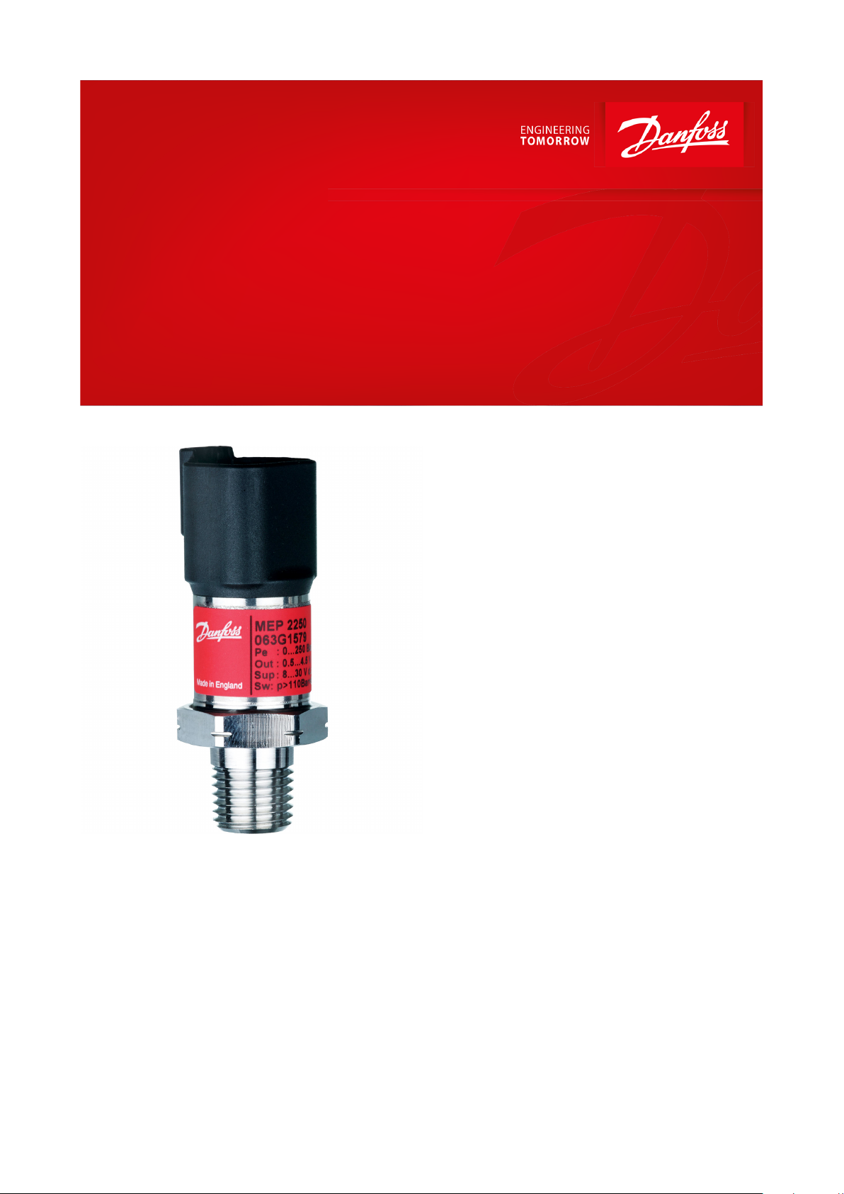
Pressure transmitter
Type MEP
For use in mobile hydraulic, industrial hydraulic and air compressor applications
MEP 2200 and MEP 2250 versions:
• For use in mobile hydraulic applications
• Dual output
Output 1: Switch output
• Hysteresis 1% FS
• Time constant 1 ms
Output 2: Analogue output
• Ratiometric or absolute voltage output
MEP 2600 and MEP 2650 versions:
• For use in mobile hydraulic, industrial
hydraulic and air compressor applications
• Single output
Output 1: Switch output
• Hysteresis 1 – 8% FS
• Time constant 8 – 512 ms
• Immunity towards VFD
The series are available in 2 versions:
• MEP 2200, MEP 2600 – without integrated
pulse-snubber
• MEP 2250, MEP 2650 – with integrated pulsesnubber
The integrated pulse-snubber oers a high
degree of protection against cavitations and
liquid hammer. The well thought out design
results in excellent vibration stability and an
exceptional robustness. The high degree of EMI
protection equips the electronic pressure
switch to meet most requirements.
AI197986426634en-000601
Page 2
P
P
Pulse-snubber
Pressure transmitter, Type MEP
Features
• Designed for use in severe OEM applications
• Excellent long term stability with zero drift
• No leakages due to fully welded design
• Wetted parts made of stainless steel
• For medium and ambient temperatures up to 125 °C
• Dual output versions with switch function and an analogue output signal:
0 – 5 V, 1 – 5 V, 1 – 6 V, 0 – 10 V, 10 – 90% ratiometric voltage as additional output
• Switch versions with customized hysteresis and time constant
• A wide range of pressure and electrical connections
• EMC protection up to 100 V/m
• Thermal overload protected
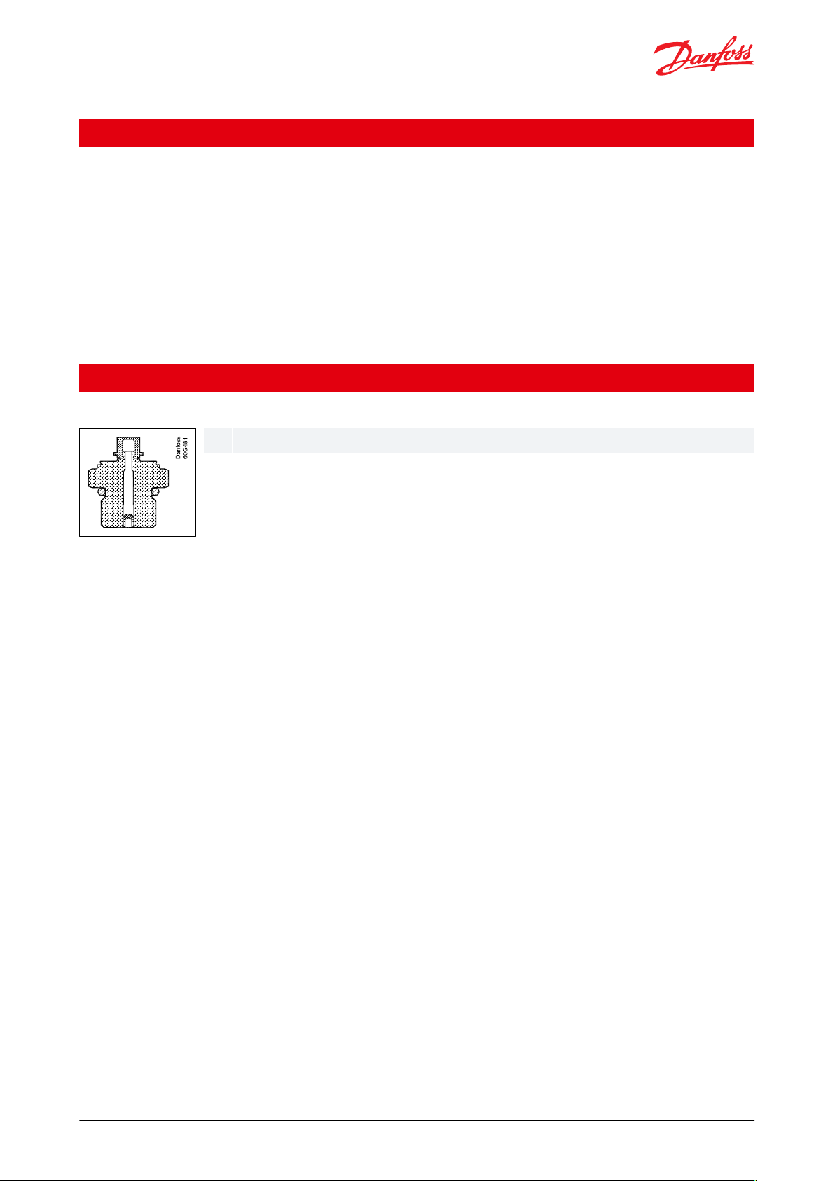
Application
Figure 1: Pulse-snubber
The pulse-snubber protects the sensor element in the event of cavitation, liquid hammer and pressure peaks, which
may occur in liquid lled systems with changes in ow velocity, e.g. fast closing of a valve or pump starts and stops.
The problem may occur on the inlet and outlet side, even at rather low operating pressures. The media viscosity has
only little eect on the response time.
Even at viscosities up to 100 cSt, the response time will not exceed 4 ms.
© Danfoss | Climate Solutions | 2021.03 AI197986426634en-000601 | 2
Page 3
Type
MEP 2200 and MEP 2250
MEP 2600 and MEP 2650
Dual output (Switch and Analogue - output)
Switch output (Switch - output)
Switch Hysteresis
~ 1% FS
(1)
1 – 8% FS
Switch Time delay
1 ms
8 – 512 mS
Accuracy
(incl. non-linearity, hysteresis and repeatability)
2% FS
2% FS (1 – 5% Hysteresis)
3% FS (6 – 8% Hysteresis)
Thermal accuracy
< ± 0.15% FS / 10K
< ± 0.15% FS / 10K
Features
Values
Nominal pressure
[bar]
1016254060
100
160
250
400
500
600
1000
(2)
1600
(2)
2200
(2)
Overload pressure
30488080140
200
320
500
800
1400
1400
2000
2500
3000
Burst pressure
400
640
800
800
1400
2000
1600
2500
4000
> 4000
> 4000
> 4000
> 4000
> 4000
Features
Values
Nominal pressure [bar]
1016254060
100
160
250
400
500
600
Overload pressure
3048120
120
210
300
480
750
1200
2100
2100
Burst pressure
400
640
800
800
1400
2000
1600
2500
4000
> 4000
> 4000
Type
MEP 2200 and MEP 2250
MEP 2600 and MEP 2650
Dual output (Switch and Analogue - output)
Switch output (Switch - output)
Max. load
(3)
500 mA
500 mA
Electrical connector types
See Electrical connections
See Electrical connections
Max. inrush load
1.6 A
600 mA
Supply voltage
8 – 32 V
Over/reverse voltage
± 36 V
± 33 V
Nom. output signal (Short-circuit protected)
NPN and PNP
NPN
0 – 5, 1 – 5, 1 – 6 V
0 – 10 V
10 – 90% ratiometric
Supply voltage [UB], polarity protected
8 – 32 V
12 – 32 V
–
Supply – current consumption
4.5 mA
4.5 mA
4.5 mA
Output inpedance
≤ 90 Ω
≤ 90 Ω
≤ 90 Ω
Load [RL] (connected to 0 V)
RL ≥ 10 kΩ
RL ≥ 10 kΩ
RL ≥ 5 kΩ
Load [RL] (connected to + V)
Not possible
Not possible
RL ≥ 5 kΩ
Features
Values
Media temperature range
- 40 – 125 °C
Ambient temperature range
-40 – 125 °C
Compensated temperature range
- 40 – 125 °C
Transport temperature range
-55 – 150 °C
EMC – Emission
EN 61326-2-3: 2013
EMC Directive
2014/30/EU
EMC – Immunity RF eld
100 V/m, 26 Mhz – 1 GHz
EN 61326-2-3 Cable < 30 m
3 V/m, 1.4 GHz – 2.7 GHz
Pressure transmitter, Type MEP
Product specication
Technical data
Table 1: Performance (EN 60770)
(1)
(1)
For detailed information please contact Danfoss.
For detailed information please contact Danfoss.
Table 2: Overload and burst pressure – without pulse-snubber
(2)
(2)
Only available wih M12 × 11.5 P high pressure port, type FC06. Please contact Danfoss.
Only available wih M12 × 11.5 P high pressure port, type FC06. Please contact Danfoss.
Table 3: Overload and burst pressure – with integrated pulse-snubber
Table 4: Electrical specications
(3)
(3)
For inductive load limits, please contact Danfoss.
For inductive load limits, please contact Danfoss.
Table 5: Secondary output reference for MEP 2200 and 2250
Table 6: Technical data
© Danfoss | Climate Solutions | 2021.03 AI197986426634en-000601 | 3
Page 4

Features
Values
Electrical performance comply with
ISO 7637 pulse 1 – 4 V (MEP 26XX)
ISO 7637-2 / ISO 16750 (MEP 22XX) (pulse 5b <45 V)
Vibration stability
20 g, 10 – 2000 Hz, sinus
EN 60068-2-6
Shock resistance
100 g
EN 60068-2-27
Enclosure (depending on electrical connection)
see page 8
Materials
Wetted parts
17 – 4 PH
Enclosure
AISI 304 or plastic
Pressure connection
17 – 4 PH
Electrical connection
See Electrical connections
Code no.
Switch state change – NC and NO
NPN and PNP connection
Code 1
Normally open (NO)
(1)
Switch state
Set point
Hysteresis 1% FS
bar
high
low
Danfoss
60G498
NPN – dual output
NPN / Switch to ground
+ Supply
Load
- Supply
Pressure signal
(absolute and ratio
metric mode)
Danfoss
60G499
Code 2
Normally closed (NC)
(2)
Switch state
Set point
Hysteresis 1% FS
bar
high
low
Danfoss
60G500
NPN – dual output
NPN / Switch to ground
+ Supply
Load
- Supply
Pressure signal
(absolute and ratio
metric mode)
Danfoss
60G499
Code 3
Normally open (NO)
(1)
Switch state
Set point
Hysteresis 1% FS
bar
high
low
Danfoss
60G498
PNP – dual output
PNP / Switch to supply
+ Supply
Load
- Supply
Pressure signal
(absolute voltage)
Danfoss
60G501
Code 4
Normally closed (NC)
(2)
Switch state
Set point
Hysteresis 1% FS
bar
high
low
Danfoss
60G500
PNP – dual output
PNP / Switch to supply
+ Supply
Load
- Supply
Pressure signal
(absolute voltage)
Danfoss
60G501
Pressure transmitter, Type MEP
Table 7: Mechanical conditions
Conguration codes
MEP 2200 and MEP 2250
Table 8: Conguration codes for MEP 2200 and MEP 2250
(1)
NO:
© Danfoss | Climate Solutions | 2021.03 AI197986426634en-000601 | 4
Page 5

Code no.
Switch state change – NC and NO
NPN and PNP connection
Code 5
Normally open (NO)
(1)
Switch state
Set point
Hysteresis 1% FS
bar
high
low
Danfoss
60G498
NPN – switch output
NPN / Switch to ground
+ Supply
Load
- Supply
Danfoss
60G502
Code 6
Normally closed (NC)
(2)
Switch state
Set point
Hysteresis 1% FS
bar
high
low
Danfoss
60G500
NPN – switch output
NPN / Switch to ground
+ Supply
Load
- Supply
Danfoss
60G502
Code 7
Normally open (NO)
(1)
Switch state
Set point
Hysteresis 1% FS
bar
high
low
Danfoss
60G498
PNP – switch output
PNP / Switch to supply
+ Supply
Load
- Supply
Danfoss
60G503
Code 8
Normally closed (NC)
(2)
Switch state
Set point
Hysteresis 1% FS
bar
high
low
Danfoss
60G500
PNP – switch output
PNP / Switch to supply
+ Supply
Load
- Supply
Danfoss
60G503
Pressure transmitter, Type MEP
At rising pressure (P0 - P
Max
) when reaching the set point the switch will connect the applied load
(switch state change from low to high).
At falling pressure (P
Max
- P0) when reaching the set point + hysteresis the switch will disconnect the applied load
(switch state change from high to low).
(2)
NC:
At rising pressure (P0 - P
Max
) when reaching the set point the switch will disconnect the applied load
(switch state change from high to low).
At falling pressure (P
Max
- P0) when reaching the set point + hysteresis the switch will connect the applied load
(switch state change from low to high).
MEP 2600 and MEP 2650
Table 9: Conguration codes for MEP 2600 and MEP 2650
(1)
At rising pressure (P0 - P
(switch state change from low to high).
At falling pressure (P
(switch state change from high to low).
(2)
© Danfoss | Climate Solutions | 2021.03 AI197986426634en-000601 | 5
NO:
NC:
Max
) when reaching the set point the switch will connect the applied load
Max
- P0) when reaching the set point + hysteresis the switch will disconnect the applied load
Page 6

Type code
C1C3C7
M12 × 1
EN60947-5-2
Deutsch DT04-4P
Deutsch DT04-3P
NOTE:
The diameter of all housings is
19 mm.
18.3 9.7
M12X1P
38
1.9
21
25
3.4
38
Type code
BD08
PT04
AC04/AF04
AC02/AF02
GB04
Recommended
torque
18 – 20 Nm
2 – 3 turns after
fnger tightend
2 – 3 turns after
fnger tightend
2 – 3 turns after
fnger tightend
30 – 35 Nm
7⁄16 – 20 UNF-2A
1⁄4 – 19 Pt
1⁄4 – 18 NPT / NPTF
1⁄8 – 27 NPT / NPTF
G 1⁄4 A DIN 3852-E
Type code
C1C3C7
Key
Danfoss
60G505
1 4
2 3
Danfoss
60G506
A
B
C
M12x1 EN60947-5-2
Deutsch DT04-4P
Deutsch DT04-3P
Enclosure
IP67
IP67
IP67
Material
SS, PBT 30%
GFR
Gold (Au) plated
Glass lled PBT 30%
GFR
Gold (Au) plated
Glass lled PBT 30%
GFR
Tin (Sn) plated
Electrical connections, MEP 22XX
Pin 1: + supply
Pin 2: pressure output
Pin 3: ÷ supply
Pin 4: switch output
Pin 1: ÷ supply
Pin 2: + supply
Pin 3: switch output
Pin 4: pressure output
Pin A: + supply
Pin B: ÷ supply
Pin C: switch output
Electrical connections, MEP 26XX
Pin 1: + supply
Pin 2: switch output
Pin 3: ÷ supply
Pin 4: N/A buried
Pin A: + supply
Pin B: ÷ supply
Pin C: switch output
Pressure transmitter, Type MEP
At rising pressure (P0 - P
Max
) when reaching the set point the switch will disconnect the applied load
(switch state change from high to low).
At falling pressure (P
Max
- P0) when reaching the set point + hysteresis the switch will connect the applied load
(switch state change from low to high).
Dimensions / Combinations
Table 10: Dimensions / Combinations
Table 11: Dimensions / Combinations with recommended torque
NOTE:
HEX is 22 mm across ats.
Electrical connections
Table 12: Electrical connections
© Danfoss | Climate Solutions | 2021.03 AI197986426634en-000601 | 6
Page 7

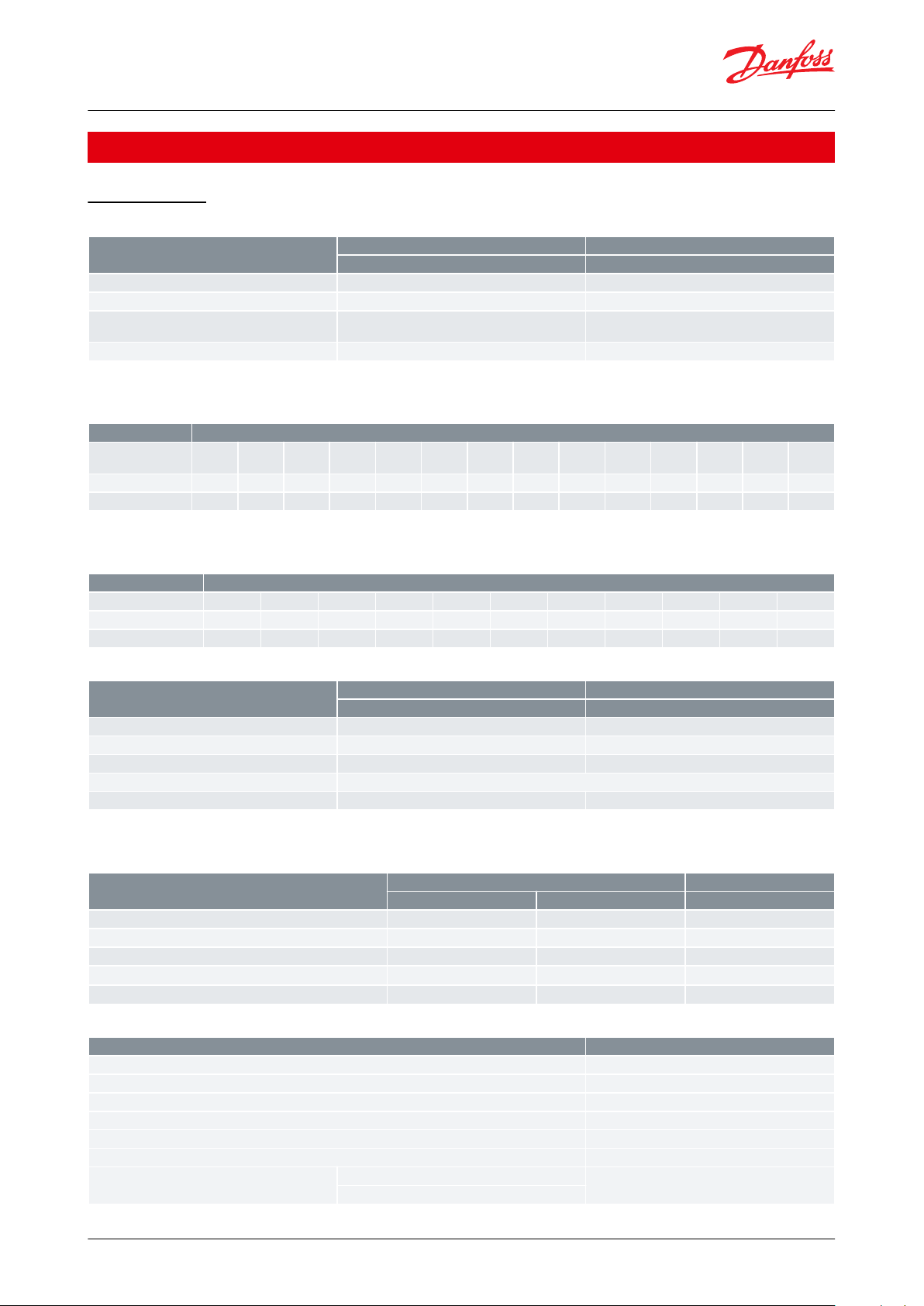
Ordering standard for dual output version type MEP 2200 and MEP 2250
MEP 22..
-
Gasket
Defined type
of pressure connection
Pressure connection (Hex 22)
Standard 0 0 BD08 7/16 – 20 UNF-2A
1)
With pulse-snubber 5 0 AC04/AF04 1/4 – 18 NPT/NPTF
AC02/AF02 1/8 – 27 NPT/NPTF
Measuring range GB04 G 1/4 A DIN 3852-E
1)
0 – 10 bar 2 0 PT04 1/4 – 19 PT
0 – 16 bar 2 2
0 – 25 bar 2 4 Electrical connection
0 – 40 bar 2 6 C 1 M12 x 1 EN60947-5-2
0 – 60 bar 2 8 C 3 Deutsch plug DT04-4P
0 – 100 bar 3 0
0 – 160 bar 3 2
C 7 Deutsch DT04-3P
0 – 250 bar 3 4
0 – 400 bar 3 6 Time constant
0 – 600 bar 3 8 0 1 ms
Hysteresis
Configuration code 1 1% FS
See page 4 1
See page 4 2 Secondary output signal
See page 4 3 2 0 – 5 V
See page 4 4 3 1 – 5 V
4 1 – 6 V
5 0 – 10 V
6 Ratiometric, 10 – 90% (NPN only)
0 No secondary output required
Switch point
To be entered in [bar]
x x x
1)
Incl. Viton gasket. Min. medium temperature is -25 °C
-
Pressure transmitter, Type MEP
Ordering
Dual output version, type MEP 2200 and MEP 2250
Figure 2: MEP 2200 and MEP 2250
© Danfoss | Climate Solutions | 2021.03 AI197986426634en-000601 | 7
Page 8

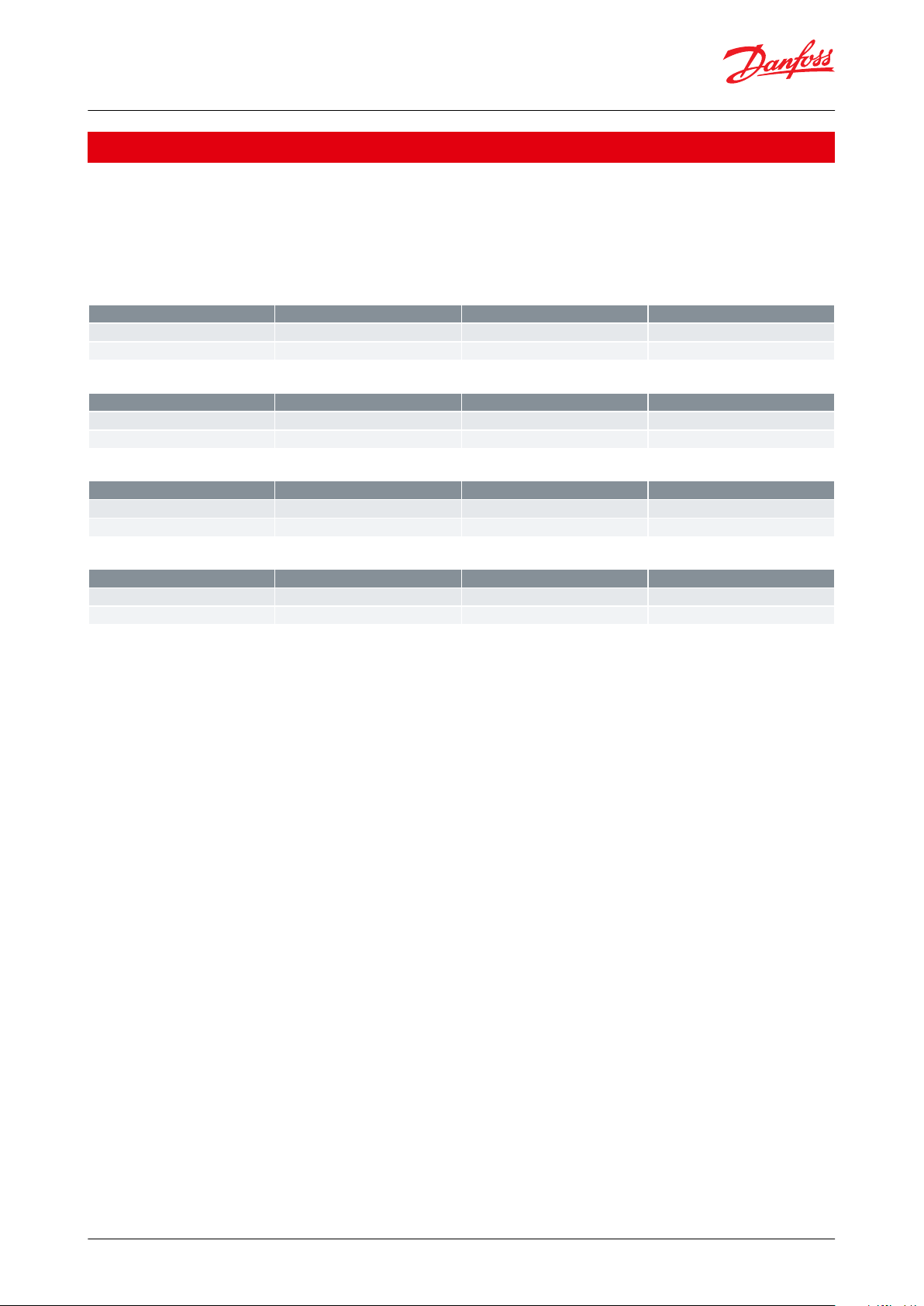
Ordering standard for switch version type MEP 2600 and MEP 2650
MEP 26..
-
Gasket
Defined type
- of pressure connection
Standard 0 0 Pressure connection (Hex 22)
With pulse-snubber 5 0 BD08 7/16 – 20 UNF-2A
1)
AC04/AF04 1/4 – 18 NPT/NPTF
Measuring range AC02/AF02 1/8 – 27 NPT/NPTF
0 – 10 bar 2 0 GB04 G 1/4 A DIN 3852-E
1)
0 – 16 bar 2 2 PT04 1/4 – 19 PT
0 – 25 bar 2 4
0 – 40 bar 2 6 Electrical connection
0 – 60 bar 2 8 C 1 M12 x 1 EN60947-5-2
0 – 100 bar 3 0 C 7 Deutsch DT04-3P
0 – 160 bar 3 2
0 – 250 bar 3 4 Time constant
0 – 400 bar 3 6 1 8 mS
0 – 600 bar 3 8 2 16 mS
3 32 mS
4 64 mS
Configuration code 5 128 mS
See page 5 5 6 256 mS
See page 5 6 7 512 mS
See page 5 7
See page 5 8 Hysteresis
1 1% FS
Switch point 2 2% FS
To be entered in [bar]
x x x
3 3% FS
4 4% FS
Secondary output signal 5 5% FS
Not available 0 6 6% FS
7 7% FS
8 8% FS
1)
Incl. Viton gasket. Min. medium temperature is -25 °C
Pressure transmitter, Type MEP
Switch version type MEP 2600 and MEP 2650
Figure 3: MEP 2600 and MEP 2650
© Danfoss | Climate Solutions | 2021.03 AI197986426634en-000601 | 8
Page 9
File name
Document type
Document topic
Approval authority
063R1015
EU Declaration
EMCD/ROHS
Danfoss
063R1012
Manufacturers Declaration
China RoHS
Danfoss
File name
Document type
Document topic
Approval authority
063R1015
EU Declaration
EMCD/ROHS
Danfoss
063R1012
Manufacturers Declaration
China RoHS
Danfoss
File name
Document type
Document topic
Approval authority
063R1015
EU Declaration
EMCD/ROHS
Danfoss
063R1012
Manufacturers Declaration
China RoHS
Danfoss
File name
Document type
Document topic
Approval authority
063R1015
EU Declaration
EMCD/ROHS
Danfoss
063R1012
Manufacturers Declaration
China RoHS
Danfoss
Pressure transmitter, Type MEP
Certicates, declarations, and approvals
The list contains all certicates, declarations, and approvals for this product type. Individual code number may have
some or all of these approvals, and certain local approvals may not appear on the list.
Some approvals may change over time. You can check the most current status at danfoss.com or contact your local
Danfoss representative if you have any questions.
Table 13: MEP 2200
Table 14: MEP 2250
Table 15: MEP 2600
Table 16: MEP 2650
© Danfoss | Climate Solutions | 2021.03 AI197986426634en-000601 | 9
Page 10

Online support
Danfoss oers a wide range of support along with our products, including digital product information, software,
mobile apps, and expert guidance. See the possibilities below.
The Danfoss Product Store
The Danfoss Product Store is your one-stop shop for everything product related—no matter where
you are in the world or what area of the cooling industry you work in. Get quick access to essential
information like product specs, code numbers, technical documentation, certications, accessories,
and more.
Start browsing at store.danfoss.com.
Find technical documentation
Find the technical documentation you need to get your project up and running. Get direct access to
our ocial collection of data sheets, certicates and declarations, manuals and guides, 3D models
and drawings, case stories, brochures, and much more.
Start searching now at www.danfoss.com/en/service-and-support/documentation.
Danfoss Learning
Danfoss Learning is a free online learning platform. It features courses and materials specically
designed to help engineers, installers, service technicians, and wholesalers better understand the
products, applications, industry topics, and trends that will help you do your job better.
Create your Danfoss Learning account for free at www.danfoss.com/en/service-and-support/learning.
Get local information and support
Local Danfoss websites are the main sources for help and information about our company and
products. Find product availability, get the latest regional news, or connect with a nearby expert—all
in your own language.
Find your local Danfoss website here: www.danfoss.com/en/choose-region.
Danfoss can accept no responsibility for possible errors in catalogues, brochures and other printed material. Danfoss reserves the right to alter its
products without notice. This also applies to products already on order provided that such alterations can be made without subsequential
changes being necessary in specications already agreed. All trademarks in this material are property of the respective companies. Danfoss and
the Danfoss logotype are trademarks of Danfoss A/S. All rights reserved.
© Danfoss | Climate Solutions | 2021.03 AI197986426634en-000601 | 10
 Loading...