

Page 1
User Manual
PLUS+1® GUIDE Software
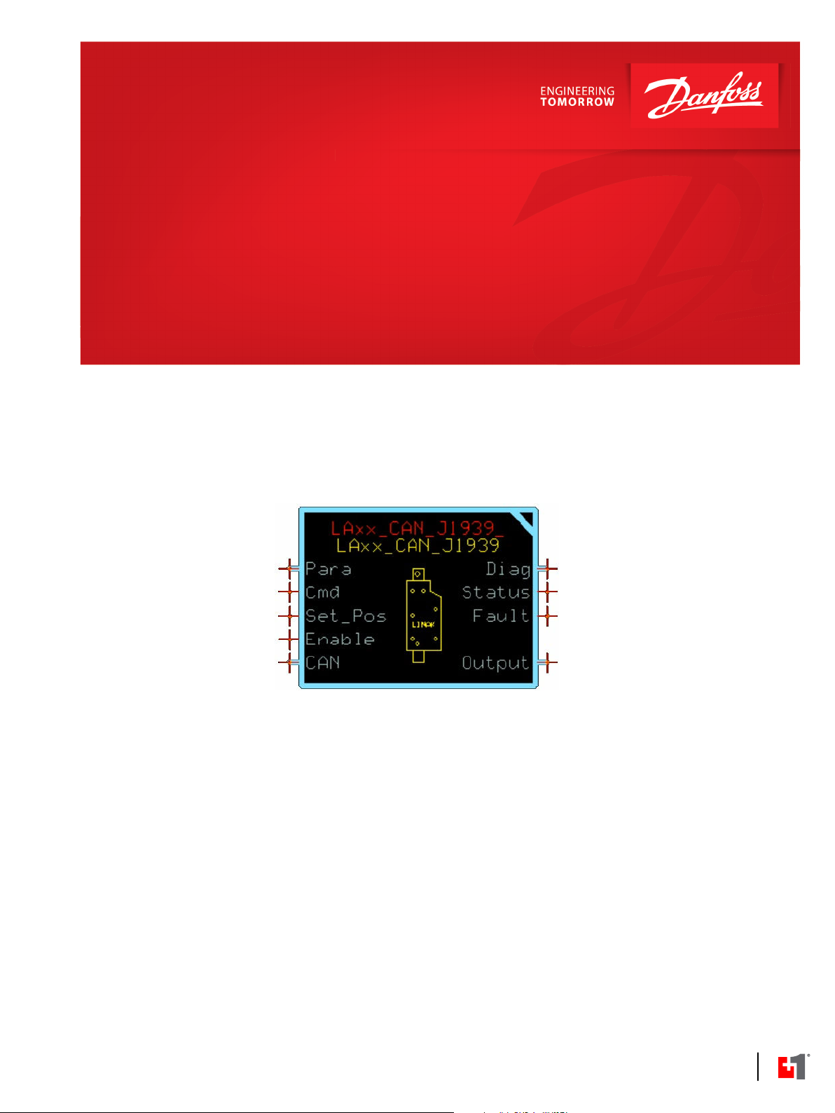
LAxx_CAN_J1939 Function Block
www.danfoss.com
Page 2

User Manual
PLUS+1® Compliant LAxx_CAN_J1939 Function Block
Revision history Table of revisions
Date Changed Rev
October 2020 Updated Outputs table 0102
June 2020 First edition 0101
2 | © Danfoss | October 2020 AQ334581384770en-000102
Page 3

User Manual
PLUS+1® Compliant LAxx_CAN_J1939 Function Block
Contents
LAxx_CAN_J1939 Function Block
Linear Actuators (LAs) Acronyms ...............................................................................................................................................4
Inputs....................................................................................................................................................................................................4
Parameters..........................................................................................................................................................................................5
Outputs................................................................................................................................................................................................ 7
Diagnostic Signals............................................................................................................................................................................9
Status Logic......................................................................................................................................................................................10
Fault Logic........................................................................................................................................................................................ 11
Use BusLink to Adjust Device Parameters.............................................................................................................................11
Parameter Settings...................................................................................................................................................................11
ECU_J1939_Src_Addr........................................................................................................................................................ 11
LA_J1939_Src_Addr........................................................................................................................................................... 11
LA_Cmd_PDU_Prio.............................................................................................................................................................11
LA_Status_Fdbk_TO...........................................................................................................................................................12
LA_Command_Tm..............................................................................................................................................................12
LA_Max_Current..................................................................................................................................................................12
LA_Max_Speed.................................................................................................................................................................... 12
LA_Start_Ramp_Tm............................................................................................................................................................12
LA_Stop_Ramp_Tm............................................................................................................................................................12
LA_Pos_Hyst......................................................................................................................................................................... 12
LA_Err_Code_Rst.................................................................................................................................................................12
LA_Toggle_Tm.....................................................................................................................................................................12
LA_Toggle_Cnt.................................................................................................................................................................... 13
LA_Curr_Fltr_Tm................................................................................................................................................................. 13
LA_Spd_Fltr_Tm.................................................................................................................................................................. 13
Identical Function Blocks Need Different Namespace Values to Successfully Compile...................................... 13
Change Namespace Value.....................................................................................................................................................13
Customizable Service Screens...................................................................................................................................................14
LAxx_CAN_J1939 Main Screen............................................................................................................................................14
Parameters Service Tool Screen.......................................................................................................................................... 16
Diagnostic Service Tool Screen............................................................................................................................................17
Error Counters Service Tool Screen....................................................................................................................................18
©
Danfoss | October 2020 AQ334581384770en-000102 | 3
Page 4
User Manual
PLUS+1® Compliant LAxx_CAN_J1939 Function Block
LAxx_CAN_J1939 Function Block
The LAxx_CAN_J1939 function block can be used as a device driver for linear actuators with CAN
interface.
Linear Actuators (LAs) Acronyms
Acronyms used in this manual are described.
Item Description
ECU Electronic Control Unit
ESS End-Stop-Switch
IC Integrated Controller
LA Linear Actuator
OC Over Current
PDU Protocol Data Unit
PI Proportional Integral Controller
PRPS Piston Rod Position Sensor
PWM Pulse Width Modulation
SA Source Address
SMPS Switched Mode Power Supply
TO Time Out
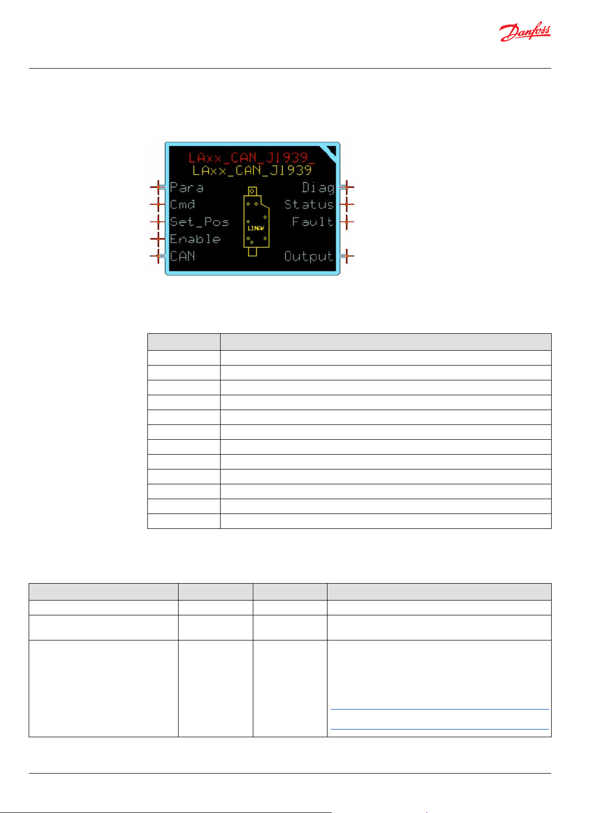
Inputs
Inputs to the LAxx_CAN_J1939 function block are described.
Item Type Range Description [Unit]
Para BUS —— Contains parameters for the function block.
Loop_Tm U16 0-65535 Processing time of one program loop.
[ms]
Cmd S8 -1-3 Input command.
-1: Retract.
0: Stop.
1: Extend.
2: Run to position.
3: Reset.
If Cmd is set to 2 (Run to Position) the input signal Set_Pos is
used to set the desired piston rod position.
4 | © Danfoss | October 2020 AQ334581384770en-000102
Page 5
User Manual
PLUS+1® Compliant LAxx_CAN_J1939 Function Block
LAxx_CAN_J1939 Function Block
Item Type Range Description [Unit]
Set_Pos U16 0- 64255 Desired piston rod position.
This input signal is used if Cmd is set to 2 (Run to position).
[0.1 mm]
Enable BOOL T/F Enables the function of the P1C LAxx_CAN_J1939 block.
T: Enabled.
F: Disabled.
CAN.Port PORT
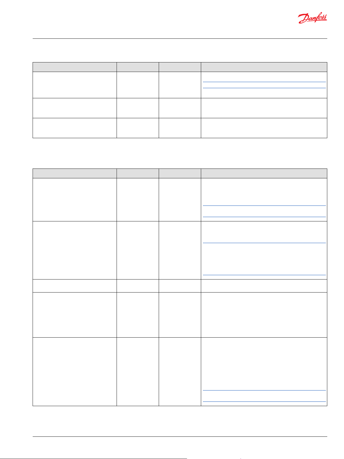
Parameters
The LAxx_CAN_J1939 function block's operating characteristics are set by para bus input signals.
Item Type Range Description [Unit]
ECU_J1939_Src_Addr
U8
—— Determines which physical CAN port of the hardware to receive
data from. This variable can be found in the CAN sub-bus if
using the Main Template.
0-253
Unique number associated with the actual instance of the P1C
block. The value is the source address (SA) placed in outgoing
J1939 messages transmitted from the P1C block instance to the
appropriate LA.
The P1C instance communicates to the LA with the source
address (SA) specified in the parameter LA_J1939_Src_Addr.
LA_J1939_Src_Addr
LA_CMD_PDU_Prio
LA_Status_Fdbk_TO
LA_Command_Tm
U8
U8
U16
U16
0-253
0-7 CAN/J1939 PDU priority for the command message being sent
5-10000
0-10000
Unique number associated with the LA this P1C block is
communicating with. The value is the SA placed in outgoing
J1939 messages transmitted from the LA to the ECU.
The LA communicates to P1C with SA specified in the
parameter ECU_J1939_Src_Addr. The value must be unique in
the CAN/J1939 network, and it must be set in the LA either by
the BusLink Configuration and Diagnostic tool or by connecting
of address pins to power supply voltage. See LINAK SAE J1939
CAN bus User Manual for more details.
from the ECU to the LA.
Time-out value for reception of Proprietary B / J1939 messages
from the LA. This status message contains:
Actual piston rod position.
•
Actual current.
•
Status flags.
•
Error code.
•
[ms]
Transmission period for Proprietary A / J1939 messages. This
status message contains:
Desired piston rod position.
•
Maximum current.
•
Maximum speed.
•
Start ramping time.
•
Stop ramping time.
•
[ms]
If the parameter is set to zero, command message transmission
from the ECU to the LA is stopped.
©
Danfoss | October 2020 AQ334581384770en-000102 | 5
Page 6

User Manual
PLUS+1® Compliant LAxx_CAN_J1939 Function Block
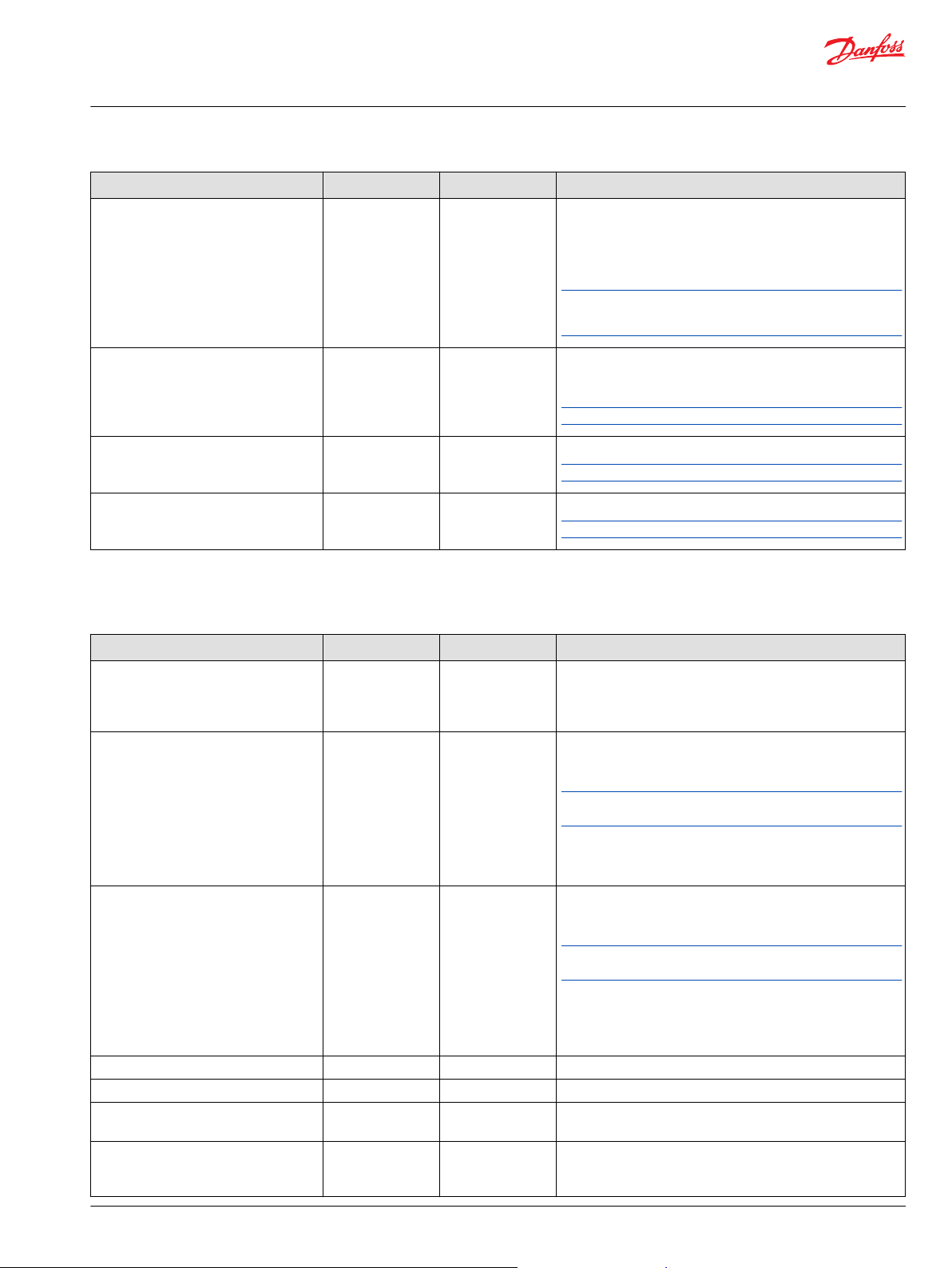
LAxx_CAN_J1939 Function Block
Item Type Range Description [Unit]
LA_Max_Current
U16
0-62500
Maximum allowed current limitation.
The Maximum Current Level (Max_Current_Lvl) being sent to
the LA is calculated as follows:
Max_Current_Lvl = ROUND(LA_Max_Current / 250).
[mA]
If LA_Max_Current is equal to 0 the default value for maximum
current memorized in LA is used. The default value must be set
by BusLink Configuration and Diagnostic tool. In this case
Max_Current_Lvl is set to 251.
LA_Max_Speed
LA_Start_Ramp_Tm
LA_Stop_Ramp_Tm
LA_Pos_Hyst
U16
U16
U16
U16
0 to 10000
0-5000
0-5000
0-10000
Maximum allowed speed limitation.
The Maximum Speed Level (Max_Speed_Lvl) being sent to
Linear Actuator is calculated as follows:
Max_Speed_Lvl = ROUND(LA_Max_Speed / 50).
Maximum piston rod speed is affected by means of PWM duty
cycle limitation. 10000 is associated with full speed (100%), 0 is
associated with stop state (0%).
[0.01%]
If LA_Max_Speed is equal to 0 the default value for maximum
speed memorized in LA is used. The default value must be set
by BusLink Configuration and Diagnostic tool. In this case
Max_Speed_Lvl is set to 251.
Soft start ramping time.
The soft start ramping time level (Start_Ramp_Tm_Lvl) being
sent to LA is calculated as follows:
Start_Ramp_Tm_Lvl = ROUND(LA_Start_Ramp_Tm / 20).
[ms]
Soft stop ramping time.
The soft stop ramping time level (Stop_Ramp_Tm_Lvl) being
sent to LA is calculated as follows:
Stop_Ramp_Tm_Lvl = ROUND(LA_Stop_Ramp_Tm / 20).
[ms]
Position hysteresis for the piston rod.
If ABS(Set_Pos – Rod_Pos) < LA_Pos_Hyst then the piston rod
is stopped and Cmd 0 (Stop) is transmitted one time to the LA.
[0.1 mm]
The parameter is used when Cmd is equal to 2 (Run to Position).
LA_Err_Code_Rst
U8
0-10
Reset level for faults.
All faults below this level are automatically reset by means of
transmission of the command Cmd equal to 3 (Reset).
Error codes are:
0: No error.
1: Hall error. Lowest priority.
2: Over voltage.
3: Under voltage.
4: Fail to maintain CAN keep alive signal.
5: ESS error.
6: Power on block state.
7: Temperature error.
8: Heartbeat error (internal).
9: SMPS error (internal). Highest priority.
Each Error Code is reset if this parameter is set to 10.
6 | © Danfoss | October 2020 AQ334581384770en-000102
Page 7
User Manual
PLUS+1® Compliant LAxx_CAN_J1939 Function Block
LAxx_CAN_J1939 Function Block
Item Type Range Description [Unit]
LA_Toggle_Tm
U16
10-2500
This parameter is used in Toggle Mode.
Maximum toggle duration for commands if overcurrent occurs
(“Retract” -> “Extend” -> “Retract” ->… or “Extend” -> “Retract” > “Extend” ->…).
[ms]
The initial direction of the piston rod movement in toggle mode
is dependent on the last command being sent to the Linear
Actuator.
LA_Toggle_Cnt
LA_Curr_Fltr_Tm
LA_Spd_Fltr_Tm
U8
U16
U16
0-100
0-1000
0-1000
This parameter is used in Toggle Mode.
Maximum number of attempts for toggle if an overcurrent
event occurred.
If the value is set to 0, then the toggle mode is not activated.
Time constant for current filtering (debounce).
Current is filtered with an exponential filter.
Time constant for speed filtering (debounce).
Piston rod speed is filtered with an exponential filter.
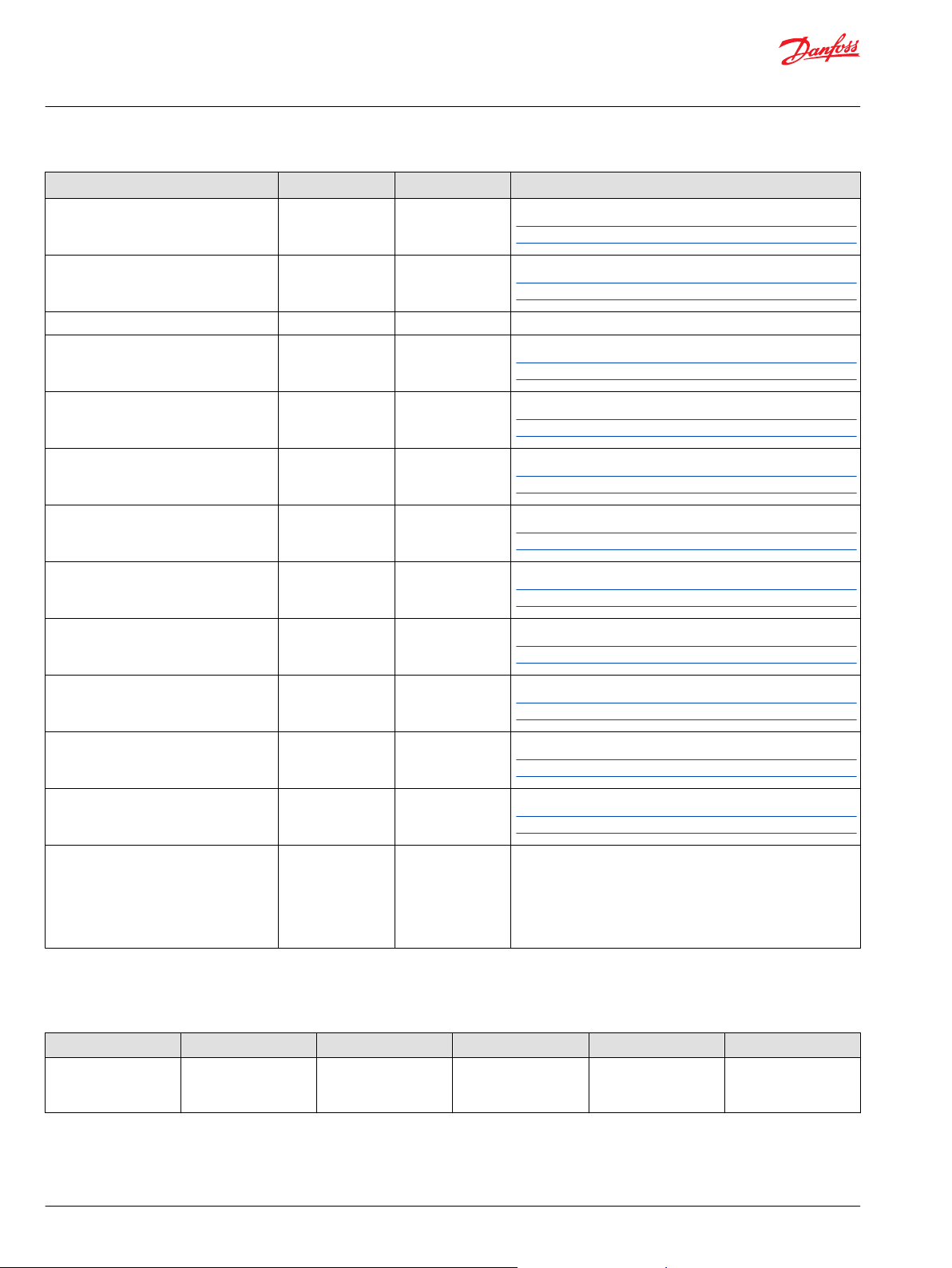
Outputs
Outputs of the LAxx_CAN_J1939 function block are described.
Item Type Range Description [Unit]
Diag
Status
Fault
Output
Rod_Pos
BUS —— This bus provides diagnostic values for troubleshooting.
In addition, all inputs, parameters, and output signals are
contained inside of the bus. See the description for diagnostic
signals in the Diagnostic Signals topic.
U16
U16
BUS ——
BUS ——
Pos
U16
Flt
BOOL T/F Actual piston rod position fault flag.
0, 0x8008
0, 0x8001, 0x8002
0-64255
This signal indicates if a parameter fault is declared.
It is a bitwise code where multiple items can be reported at a
time.
Input data types must exactly match the indicated type to
successfully compile.
The following status codes are provided:
0x0000: No fault.
0x8008: At least one parameter is out of range.
This signal indicates if an input fault is declared.
It is a bitwise code where multiple items can be reported at a
time.
Input data types must exactly match the indicated type to
successfully compile.
The following fault codes are provided:
0x0000: No fault.
0x8001: An input value is too low.
0x8002: An input value is too high.
Bus with the output signals.
Bus with piston rod position feedback signals.
Actual piston rod position feedback.
[0.1 mm]
T: Fault.
F: No fault.
©
Danfoss | October 2020 AQ334581384770en-000102 | 7
Page 8

User Manual
PLUS+1® Compliant LAxx_CAN_J1939 Function Block
LAxx_CAN_J1939 Function Block
Item Type Range Description [Unit]
Status
Rod_Spd
Mtr_Curr
Err_Code
In_State
BUS ——
OC
BOOL T/F Actual Overcurrent status flag.
ESS
U8
Run_Dir
U8
Flt
BOOL T/F Actual status fault flag.
BUS ——
Spd
U16 0-10000 Actual relative piston rod speed.
Flt
BOOL T/F Actual relative piston rod speed fault.
BUS ——
Curr U16 0-62500
Flt
BOOL T/F Actual DC motor current fault flag.
BUS ——
EC
U8
Flt
BOOL T/F Actual error code fault flag.
BUS ——
In_1
U8
0-3
0-3
0-9
0-3
Bus with status feedback signals.
T: Active.
F: Not active.
ESS state flag.
0: Transition state.
1: Full retracted.
2: Full extended.
3: Fault.
Actual piston rod run direction status.
0: Stopped.
1: Running in (retraction).
2: Running out (extension).
3: Fault.
T: Fault.
F: No fault.
Bus with piston rod speed signals.
Speed is relative to nominal speed, for example, 5000 means
50% of nominal speed.
[0.01%]
T: Fault.
F: No fault.
Bus with DC motor current signals.
Actual DC motor current.
[mA]
T: Fault.
F: No fault.
Bus with error code signals.
Actual error code.
0: No error.
1: Hall error. Lowest priority.
2: Overvoltage
3: Undervoltage
4: Fail to maintain CAN keep alive signal.
5: ESS error.
6: Power on block state.
7: Temperature error.
8: Heartbeat error (internal).
9: SMPS error (internal). Highest priority.
T: Fault.
F: No fault.
Bus with input level state signals.
Actual input 1 level state.
0: 0 – 25% of Vcc.
1: 25 – 50% of Vcc.
2: 50 – 75% of Vcc.
3: 75 – 100% of Vcc.
8 | © Danfoss | October 2020 AQ334581384770en-000102
Page 9

User Manual
PLUS+1® Compliant LAxx_CAN_J1939 Function Block
LAxx_CAN_J1939 Function Block
Item Type Range Description [Unit]
Diagnostic Signals
In_2
U8
In_3
U8
Flt
BOOL T/F Actual input level state fault flag.
The diagnostic bus contains signals for input, parameter, and output signals.
Input, parameter, and output signals are described in previous topics.
0-3
0-3
Actual input 2 level state.
0: 0 – 25% of Vcc.
1: 25 – 50% of Vcc.
2: 50 – 75% of Vcc.
3: 75 – 100% of Vcc.
Actual input 3 level state.
0: 0 – 25% of Vcc.
1: 25 – 50% of Vcc.
2: 50 – 75% of Vcc.
3: 75 – 100% of Vcc.
T: Fault.
F: No fault.
Item Type Range Description [Unit]
Tx
Pos_Cmd
Max_Current_Lvl
Max_Speed_Lvl
Start_Ramp_Tm_Lvl
Stop_Ramp_Tm_Lvl
Send_Cnt
OverRun_Cnt
Pend_Cnt
BUS ——
U16 0-64259 Desired position command transmitted to the LA by CAN J1939.
U8 0-251
U8 0-251
U8 0-250
U8 0-250
U32 0-0xFFFFFFFF Actual count for commands sent.
U32 0-0xFFFFFFFF Actual Transmission Overrun count.
U32 0-0xFFFFFFFF Actual Transmission Pending count.
Bus with signals related to data transmission (Tx).
0 to 64255: Desired position (in 0.1mm).
64256: Clear error code register.
64257: Command run out (Extension).
64258: Command run in (Retraction).
64259: Command stop.
Maximum allowed current level. See parameter
LA_Max_Current for more details.
Maximum allowed speed level. See parameter LA_Max_Speed
for more details.
Soft start ramping time level. See parameter
LA_Start_Ramp_Tm for more details.
Soft stop ramping time level. See parameter
LA_Stop_Ramp_Tm for more details.
Count rolls over to 0.
Count rolls over to 0.
Count rolls over to 0.
Rst_Cnt
Rx
Data_Flt_Cnt
©
Danfoss | October 2020 AQ334581384770en-000102 | 9
U32 0-0xFFFFFFFF Actual count for Reset command. The counter is incremented
when the LA gets an error and it must be automatically reset.
See parameter LA_Err_Code_Rst for more details.
Count rolls over to 0.
BUS ——
U32 0-0xFFFFFFFF Actual reception data fault count.
Bus with signals related to data reception (Rx).
Count rolls over to 0.
Page 10
User Manual
PLUS+1® Compliant LAxx_CAN_J1939 Function Block
LAxx_CAN_J1939 Function Block
Item Type Range Description [Unit]
Msg_Cnt
U32 0-0xFFFFFFFF Actual count of received messages.
Count rolls over to 0.
Err_Cnt
Rx_TO_Cnt
Cnt_Hall_Error
Cnt_Over_Voltage_Error
Cnt_Under_Voltage_Error
Cnt_CAN_Bus_Comm_Error
Cnt_ESS_Error
Cnt_Pwr_On_BS_Error U32 0-0xFFFFFFFF Actual count for Power on Block State errors.
Cnt_Temperature_Error U32 0-0xFFFFFFFF Actual count for Temperature errors.
U32 0-0xFFFFFFFF Actual count for timeout events for received messages.
Counter rolls over to 0.
BUS ——
U32 0-0xFFFFFFFF Actual count for Hall sensor errors.
U32 0-0xFFFFFFFF Actual count for Overvoltage errors.
U32 0-0xFFFFFFFF Actual count for Undervoltage errors.
U32 0-0xFFFFFFFF Actual count for CAN bus communication errors.
U32 0-0xFFFFFFFF Actual count for End Stop Switch (ESS) errors.
Bus with signals related to error counter signals.
Count rolls over to 0.
Count rolls over to 0.
Counter rolls over to 0.
Count rolls over to 0.
Count rolls over to 0.
Count rolls over to 0.
Count rolls over to 0.
Cnt_Heartbeat_Error U32 0-0xFFFFFFFF Actual count for Heartbeat (internal) errors.
Count rolls over to 0.
Cnt_SMPS_Error U32 0-0xFFFFFFFF Actual count for Switched-Mode Power Supply (SMPS) errors.
Count rolls over to 0.
Cmd_Act
S8 -1-3 Internal actual command.
-1: Retract. Run in.
0: Stop.
1: Extend. Run out.
2: Run-to-position.
3: Reset.
Status Logic
The status code indicates whether the parameters used in the function are within their valid range.
Condition Hex
Status 0x8008 1000 0000 0000 1000 At least one of the
*
Bit 16 set to 1 identifies a standard Danfoss status or fault code.
*
Binary Cause Response Correction
parameters is out of
range.
Status code.
Transmission is
disabled.
Correct parameter
values.
10 | © Danfoss | October 2020 AQ334581384770en-000102
Page 11
User Manual
PLUS+1® Compliant LAxx_CAN_J1939 Function Block
LAxx_CAN_J1939 Function Block
Fault Logic
The fault code indicates whether the inputs of the function are within their valid range.
Condition Hex
An input is too low. 0x8001 1000 0000 0000 0001 Cmd is less than -1. Fault code.
An input is too high.
*
Bit 16 set to 1 identifies a standard Danfoss status or fault code.
Use BusLink to Adjust Device Parameters
*
0x8002
Binary Cause Response Correction
Transmission is
disabled.
1000 0000 0000 0010
Cmd is greater than 3
or Set_Pos is greater
than 64255.
Fault code.
Transmission is
disabled.
Use the BusLink Configuration and Diagnostic tool to initially configure the LAxx device with J1939
option.
Connect the LAxx device to your PC through the USB2LIN interface and start LINAK BusLink Configuration
and Diagnostic tool.
For details on how to connect your device to USB2LIN interface, refer to the user manual of BusLink
Configuration and Diagnostic.
Correct Cmd value.
Correct Cmd or
Set_Pos input value.
Adjust the following device parameters as desired.
Default CAN Address (J1939 Source Address)
•
Current Limit Inwards
•
Current Limit Outwards
•
Maximum speed
•
Parameter Settings
An overview about how to adjust parameters for the PLUS+1® compliance block is provided.
ECU_J1939_Src_Addr
Set the ECU_J1939_Src_Addr parameter.
The parameter must be unique in J1939 network. Each LAxx_CAN_J1939 block instance communicates
with exactly one Linear Actuator (1:1).
LA_J1939_Src_Addr
Set LA_J1939_Src_Addr parameter to the value of the CAN address set by BusLink or by connecting
address pins (pin 1, pin 2, pin 3) to power supply voltage.
The parameter must be unique in J1939 network. Each Linear Actuator instance communicates with
exactly one LAxx_CAN_J1939 Compliance Block (1:1). The default value is 0x80 (128).
LA_Cmd_PDU_Prio
Set LA_Cmd_PDU_Prio parameter to desired value
0 is highest priority, 7 is lowest priority.
PDUs with a higher priority win arbitration over J1939 messages. The default value is 6.
©
Danfoss | October 2020 AQ334581384770en-000102 | 11
Page 12

User Manual
PLUS+1® Compliant LAxx_CAN_J1939 Function Block
LAxx_CAN_J1939 Function Block
LA_Status_Fdbk_TO
Set LA_Status_Fdbk_TO parameter to the expected period of feedback messages and add the time of a
possible jitter.
For instance, if the expected time for feedback messages is 200 ms and possible jitter is 50 ms, set the
parameter to 250 ms. The default value is 250 ms.
LA_Command_Tm
Set the LA_Command_Tm parameter to the desired transmission period that is sufficient for LAxx device
and the application.
The default value is 200 ms.
LA_Max_Current
Set the LA_Max_Current parameter to the maximum current allowed for the LAxx device.
If you want to use pre-defined parameter adjusted by BusLink tool, set the value to 0. The default value is
0 mA (use of pre-defined setting).
LA_Max_Speed
Set the LA_Max_Speed parameter to the maximum speed allowed for the LAxx device.
If you want to use pre-defined parameter adjusted by the BusLink tool, set the value to 0. The default
value is 0 mA (use of pre-defined setting).
LA_Start_Ramp_Tm
Set the LA_Start_Ramp_Tm parameter to the desired ramping time for piston rod acceleration.
A too-small value can cause overcurrent. The default value is 200 ms.
LA_Stop_Ramp_Tm
Set LA_Stop_Ramp_Tm parameter to the desired ramping time for piston rod deceleration.
A too-small value can cause overcurrent. The default value is 200 ms.
LA_Pos_Hyst
Set the LA_Pos_Hyst parameter to the desired hysteresis.
The parameter is used if Cmd is equal to 2 (Run-to-Position). Set the value to 0 if you do not intend to use
the hysteresis. The default value is 10, which corresponds to 1 mm.
LA_Err_Code_Rst
Set the LA_Err_Code_Rst parameter to the desired level of automatic error code reset.
Set the value to 0 if you do not intend to use automatic error code reset function. The default value is 5.
The following error codes are automatically reset by use of the default value:
•
Overvoltage.
•
Undervoltage.
•
Fail to maintain CAN keep-alive signal.
LA_Toggle_Tm
Set the LA_Toggle_Tm parameter to the desired time.
The parameter is used if an Overcurrent event occurs. The piston rod moving direction is changed after
the value specified in this parameter. The default value is 100 ms.
12 | © Danfoss | October 2020 AQ334581384770en-000102
Page 13

User Manual
PLUS+1® Compliant LAxx_CAN_J1939 Function Block
LAxx_CAN_J1939 Function Block
LA_Toggle_Cnt
Set the LA_Toggle_Cnt parameter to the desired maximum amount of piston rod moving direction
changes.
The parameter is used if an Overcurrent event occurs. The piston rod moving direction is changed
number of attempts specified in this parameter. The default value is 10.
LA_Curr_Fltr_Tm
Set the LA_Curr_Fltr_Tm parameter to the desired filter time constant for current measurement.
The default value is 100 ms.
LA_Spd_Fltr_Tm
Set the LA_Spd_Fltr_Tm parameter to the desired filter time constant for speed measurement.
The default value is 100 ms.
Identical Function Blocks Need Different Namespace Values to Successfully Compile
If you use the same function block more than once in an application, you must change each function
block’s namespace value to avoid compiler errors.
All function blocks contain Advanced Checkpoint with Namespace components that enable the PLUS+1
Service Tool to read block input and output values.
Some function blocks contain non-volatile memory components that store function block operating
parameters.
Both these components use memory names (“aliases”) to allocate memory. Identical memory names
cause compiler errors.
The namespace value adds a unique prefix to each component name to avoid errors. Keep each
namespace value short to save controller memory.
®
Change Namespace Value
To successfully compile your application, change the namespace value for function blocks that are used
more than once in an application.
©
Danfoss | October 2020 AQ334581384770en-000102 | 13
Page 14

User Manual
PLUS+1® Compliant LAxx_CAN_J1939 Function Block
LAxx_CAN_J1939 Function Block
1. In the PLUS+1® GUIDE menu bar, click the Query/Change button.
2. Click on the function block whose namespace you want to set to a unique value.
The Edit Page window opens.
3. In the Edit Page window, enter a meaningful Namespace value.
Namespace values are case-sensitive.
•
To save controller memory, use a short namespace value.
•
4. Press Enter.
5. Repeat these steps to enter unique namespace values for other identical function blocks.
Customizable Service Screens
This function block comes with pre-made service screens that you can customize when building your
Service Tool application.
The pre-made screens simplify the task of creating Service Tool applications. You can use the screens as
is. Or, you can choose screen components to place in your application.
Refer to the PLUS+1® GUIDE Service Tool Design Manual (Danfoss document number AQ152986485048)
for more information on how to create Service Tool screens.
LAxx_CAN_J1939 Main Screen This screen gives an overview of the LAxx_CAN_J1939 function block.
Item Description
Inputs ——
Enable Signal from the Enable input.
1: Function of LAxx_CAN_J1939 is enabled.
0: Function of LAxx_CAN_J1939 is disabled.
Command Input command.
-1: Retract.
0: Stop.
1: Extend.
2: Run-To-Position.
3: Reset.
Set Position Desired position.
14 | © Danfoss | October 2020 AQ334581384770en-000102
Page 15
User Manual
PLUS+1® Compliant LAxx_CAN_J1939 Function Block
LAxx_CAN_J1939 Function Block
Item Description
CAN Configuration Basic CAN configuration data.
ECU Source Address ECU Source Address, see ECU_J1939_Src_Addr parameter.
LA Source Address LA Source Address, see LA_J1939_Src_Addr parameter.
Outputs ——
Status Reports the status of the function block.
Fault Reports the faults of the function block.
Position Actual piston rod position.
Speed Actual piston rod speed.
Run Direction Piston rod traveling indicator.
0: Stop.
1: Running in (Retraction).
2: Running out (Extension).
3: Fault.
End-Stop-Switch Actual ESS status.
0: Stop.
1: Full retracted.
2: Full extended.
3: Fault.
Overcurrent Actual overcurrent status.
1: Overcurrent.
0: No overcurrent.
Current
Error Code Actual error code.
Input Status Actual input status of address pins.
Actual LA current.
0: No error.
1: Hall error. Lowest priority.
2: Overvoltage.
3: Undervoltage.
4: Fail to maintain CAN keep alive signal.
5: ESS error.
6: Power on block state.
7: Temperature error.
8: Heartbeat error (internal).
9: SMPS error (internal). Highest priority.
Pin #1 Actual input 1 level state.
0: 0 – 25% of Vcc.
1: 25 – 50% of Vcc.
2: 50 – 75% of Vcc.
3: 75 – 100% of Vcc.
Pin #2 Actual input 2 level state.
0: 0 – 25% of Vcc.
1: 25 – 50% of Vcc.
2: 50 – 75% of Vcc.
3: 75 – 100% of Vcc.
Pin #3 Actual input 3 level state.
0: 0 – 25% of Vcc.
1: 25 – 50% of Vcc.
2: 50 – 75% of Vcc.
3: 75 – 100% of Vcc.
©
Danfoss | October 2020 AQ334581384770en-000102 | 15
Page 16

User Manual
PLUS+1® Compliant LAxx_CAN_J1939 Function Block
LAxx_CAN_J1939 Function Block
Parameters Service Tool Screen This screen gives an overview of parameters for the LAxx_CAN_J1939 function block.
Item Description
Parameters ——
ECU Source Address ECU_J1939_Src_Addr parameter.
LA Source Address LA_J1939_Src_Addr parameter.
Status Feedback Timeout LA_Status_Fdbk_TO parameter.
Command Time LA_Command_TO parameter.
Position Hysteresis LA_Pos_Hyst parameter.
Error Code Reset LA_Err_Code_Rst parameter.
Toggle Time LA_Toggle_Tm parameter.
Toggle Count LA_Toggle_Cnt parameter.
Current Filter Time LA_Curr_Fltr_Tm parameter.
Speed Filter Time LA_Spd_Fltr_Tm parameter.
Maximum Current LA_Max_Current parameter.
Maximum Speed LA_Max_Speed parameter.
Start Ramping Time LA_Start_Ramp_Tm parameter.
Stop Ramping Time LA_Stop_Ramp_Tm parameter.
Corresponding Levels ——
Maximum Current Level Max_Curr_Lvl checkpoint.
Maximum Speed Level Max_Speed_Lvl checkpoint.
Start Ramping Time Level Start_Ramp_Tm_Lvl checkpoint.
Stop Ramping Time Level Stop_Ramp_Tm_Lvl checkpoint.
16 | © Danfoss | October 2020 AQ334581384770en-000102
Page 17

User Manual
PLUS+1® Compliant LAxx_CAN_J1939 Function Block
LAxx_CAN_J1939 Function Block
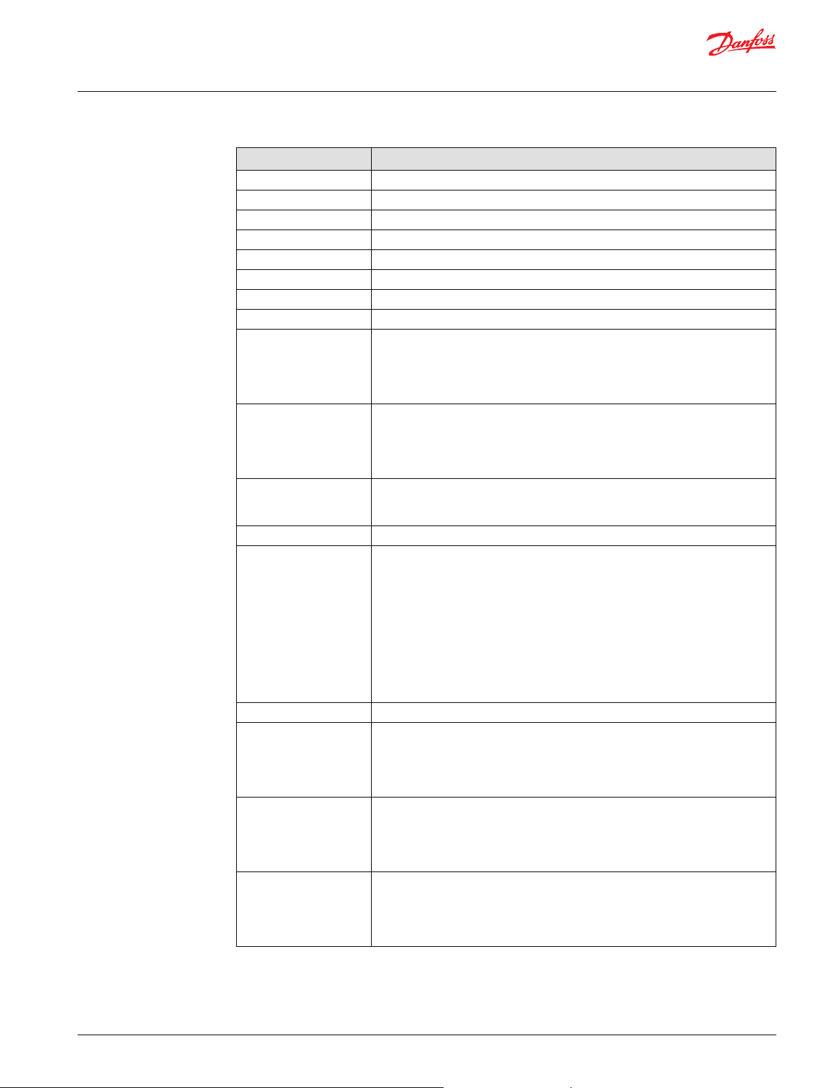
Diagnostic Service Tool Screen
This screen gives an overview of Diagnostic signals.
Item Description
Feedback Faults ——
Piston Rod Position Fault signal for piston rod position.
1: Fault.
0: No fault.
Piston Rod Speed Fault signal for piston rod speed.
1: Fault.
0: No fault.
Linear Actuator Status Fault signal for LA status.
1: Fault.
0: No fault.
Motor Current Fault signal for motor current.
1: Fault.
0: No fault.
Input Status Fault signal for input status (Input pin 1, pin 2, pin 3.)
1: Fault.
0: No fault.
Error Code Fault signal for error code.
1: Fault.
0: No fault.
Internal Signals ——
Actual Command Actual command used internally in the compliance block.
-1: Retract.
0: Stop.
1: Extend
2: Run to Position.
3: Reset.
Transmission (Tx)
counters
Tx Messages Number of transmitted commands.
——
Reset Number of reset commands.
©
Danfoss | October 2020 AQ334581384770en-000102 | 17
Page 18
User Manual
PLUS+1® Compliant LAxx_CAN_J1939 Function Block
LAxx_CAN_J1939 Function Block
Item Description
OverRun Number of overrun events.
Pend Number of pending events.
Reception (Rx) Counters ——
Rx Messages Number of received feedback messages.
Timeouts
Data Fault Number of occurred data faults (timeouts and data length faults).
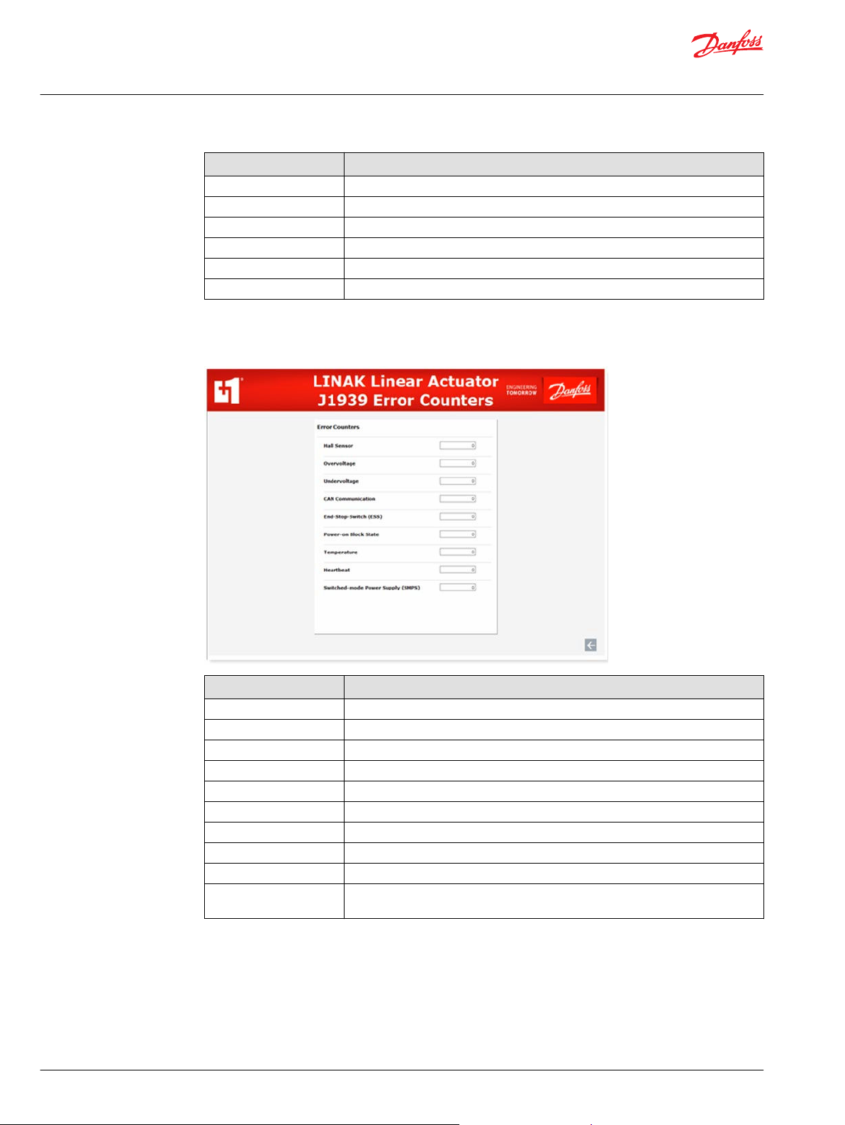
Error Counters Service Tool Screen
This screen gives an overview of Error Counter signals.
Number of occurred timeouts.
Item Description
Error Counters ——
Hall Sensor Error counter for Hall Sensor faults.
Overvoltage Error counter for Overvoltage faults.
Undervoltage Error counter for Undervoltage faults.
CAN Communication Error counter for CAN communication faults.
End-Stop-Switch (ESS) Error counter for ESS faults.
Power-on Block State Error counter for Power-on Block State faults.
Temperature Error counter for Temperature faults.
Heartbeat Error counter for Heartbeat faults.
Switched-mode Power
Supply (SMPS)
Error counter for SMPS faults.
18 | © Danfoss | October 2020 AQ334581384770en-000102
Page 19

Danfoss
Power Solutions GmbH & Co. OHG
Krokamp 35
D-24539 Neumünster, Germany
Phone: +49 4321 871 0
Danfoss
Power Solutions ApS
Nordborgvej 81
DK-6430 Nordborg, Denmark
Phone: +45 7488 2222
Danfoss
Power Solutions (US) Company
2800 East 13th Street
Ames, IA 50010, USA
Phone: +1 515 239 6000
Danfoss
Power Solutions Trading
(Shanghai) Co., Ltd.
Building #22, No. 1000 Jin Hai Rd
Jin Qiao, Pudong New District
Shanghai, China 201206
Phone: +86 21 2080 6201
Products we offer:
Hydro-Gear
www.hydro-gear.com
Daikin-Sauer-Danfoss
www.daikin-sauer-danfoss.com
Cartridge valves
•
DCV directional control
•
valves
Electric converters
•
Electric machines
•
Electric motors
•
Gear motors
•
Gear pumps
•
Hydraulic integrated
•
circuits (HICs)
Hydrostatic motors
•
Hydrostatic pumps
•
Orbital motors
•
PLUS+1® controllers
•
PLUS+1® displays
•
PLUS+1® joysticks and
•
pedals
PLUS+1® operator
•
interfaces
PLUS+1® sensors
•
PLUS+1® software
•
PLUS+1® software services,
•
support and training
Position controls and
•
sensors
PVG proportional valves
•
Steering components and
•
systems
Telematics
•
Danfoss Power Solutions is a global manufacturer and supplier of high-quality hydraulic and
electric components. We specialize in providing state-of-the-art technology and solutions
that excel in the harsh operating conditions of the mobile off-highway market as well as the
marine sector. Building on our extensive applications expertise, we work closely with you to
ensure exceptional performance for a broad range of applications. We help you and other
customers around the world speed up system development, reduce costs and bring vehicles
and vessels to market faster.
Danfoss Power Solutions – your strongest partner in mobile hydraulics and mobile
electrification.
Go to www.danfoss.com for further product information.
We offer you expert worldwide support for ensuring the best possible solutions for
outstanding performance. And with an extensive network of Global Service Partners, we also
provide you with comprehensive global service for all of our components.
Local address:
Danfoss can accept no responsibility for possible errors in catalogues, brochures and other printed material. Danfoss reserves the right to alter its products without notice. This also applies to products
already on order provided that such alterations can be made without subsequent changes being necessary in specifications already agreed.
All trademarks in this material are property of the respective companies. Danfoss and the Danfoss logotype are trademarks of Danfoss A/S. All rights reserved.
©
Danfoss | October 2020 AQ334581384770en-000102
 Loading...