

Page 1

Data sheet
Electric Regulating Valve
Type KVS
KVS is a series of electronic suction modulating
valves for AC transport and refrigeration
applications.
Accurate temperature or pressure control is
obtained by modulating the refrigerant flow in
the evaporator with a current or voltage driver.
With an EKC 368 controller (current driver) and
an AKS sensor placed in the media to be controlled, an accuracy better than ± 0.5K can be
obtained.
The balanced design provides bi-flow operation as
well as solenoid shut-off function in both flow
directions at MOPD 33 bar (478 psig).
Features • Biflow.
• High resolution for precise control.
• Wide range for all common refrigerants R22,
R134a, R404A, R407A, R407C, R407F, R422B,
R422D, R438A, R448A, R449A, R450A, R452A,
R507, R513A, R410A, R1234ze and other
refrigerants
• Balanced port design (KVS 42).
• Solenoid tight shut-off.
• Low power consumption.
• Corrosion resistant design external as well as
internal.
• Cable and connector assemblies as accessories.
• For manual operation and service of KVS valves
an AST-g service driver is available.
For further information please contact Danfoss
(Commercial Refrigeration & Air Conditioning
Controls).
© Danfoss | DCS (sw) | 2017.10
DKRCC.PD.VC1.C7.02 | 1
Page 2

.
Data sheet | Electric regulating valve type KVS 15 – KVS 42
Technical data
Electrical data
Parameter KVS 15 KVS 42
R22, R134a, R404A, R407A, R407C,
Compatible refrigerants
Refrigerant oil All mineral and ester oils All mineral and ester oils
CE marking No Yes
MOPD 33 bar / 478.6 psig 33 bar / 478 psig
Max. working pressure 45.5 bar / 660 psig 34 bar / 493 psig
Inlet fluid temperature -40 to +65 °C / -40 to +149 °F -40 to +65 °C / -40 to +149 °F
Ambient temperature -40 to +60 °C / -40 to +140 °F -40 to +60 °C / -40 to +140 °F
Total stroke 13 mm / 0.5 inch 17.2 mm / 0.68 inch
Motor enclosure IP 67 IP 67
Material of Construction
Parameter KVS 15 and KVS 42
Stepper motor type Bi-polar - permanent magnet
Step mode 2 phase full step
Phase resistance 52 Ω ±10%
Phase inductance 85 mH
Holding current
Step angle
Nominal voltage Constant voltage drive: 12 V DC -4% – 15%, 150 steps/sec.
Phase current (Using chopper drive) 100 mA RMS -4% +15%,
Max. total power Voltage / current drive: 5.5 / 1.3 W (UL: NEC class 2)
Step rate
Total steps
Full travel time
Lifting height
Reference position Overdriving against the full close position
Electrical connection M12 connector
R407F, R422B, R422D, R438A,
R448A, R449A, R450A, R452A, R507,
R513A, R410A, R1234ze and other
refrigerants
Body and AST Encloser: Brass
Connector: Copper
Constant voltage drive: Depends on application.
Chopper drive: full current allowed (100% duty cycle)
7.5° (motor),
0.9° (lead screw),
Gearing ration 8.5:1. (38/13)2:1
Constant voltage drive: 150 steps/sec.
Chopper current drive: 0 – 300 steps/sec. 300 recommended
KVS 15: 2625 [+160 / -0] steps
KVS 42: 3810 [+160 / -0] steps
KVS 15: 17 / 8.5 sec. (voltage / current)
KVS 42: 25.4 / 12.7 sec. (voltage / current)
KVS 15: 13 mm / 0.5 inch
KVS 42: 17.2 mm / 0.68 in
R22, R134a, R404A, R407A, R407C,
R407F, R422B, R422D, R438A,
R448A, R449A, R450A, R452A, R507,
R513A, R410A, R1234ze and other
refrigerants
Body and AST Encloser: Brass
Connector: Copper
Flow curves
Compatible controller / driver EKC 368 / EKD 316 or EKD 316C
KVS 15 Capacity Curve
.
.
KVS 42 Capacity Curve
© Danfoss | DCS (sw) | 1017.10
DKRCC.PD.VC1.C7.02 | 2
Page 3

Data sheet | Electric regulating valve type KVS 15 – KVS 42
Ordering
Accessories:
M12 Female Connector Cable
Spare parts
KVS valves in single pack
Rated capacity
Type
R22 R134a R404A/R507 ODF Code no.
kW TR kW TR kW TR mm in.
KVS 15 5.15 1.31 3.78 0.94 4.58 1.07
KVS 42 40.4 11 . 4 29.3 8.3 35.3 10.0
1
) Rated capacity is the valve capacity at evaporating temperature te = –10°C (14°F), condensing temperature tc = +25°C (77°F)
and pressure drop across valve ∆p = 0.2 bar (2.9 psig).
1)
Connections
single
pack
16 ⁄ 034G4252
22 ⁄ 034G4253
22 ⁄ 034G2858
28 1⁄ 034G2850
35 1⁄ 034G2851
- 1⁄ 034G2852
Actuator with integrated M12 connection
Items Description Quantity
[pcs]
34G179.10
Danfoss
Actuator with integrated M12 with Ceramic bearing
(incl. metal gasket) for KVS 15
Code no.
1 034G2088
34G179.10
Danfoss
Actuator with integrated M12 with ceramic bearing
1 034G2087
(incl. metal gasket) for KVS 42
Metal Gasket 1 034G2344
© Danfoss | DCS (sw) | 1017.10
DKRCC.PD.VC1.C7.02 | 3
Page 4
34G211.10
Pr
C
Data sheet | Electric regulating valve type KVS 15 – KVS 42
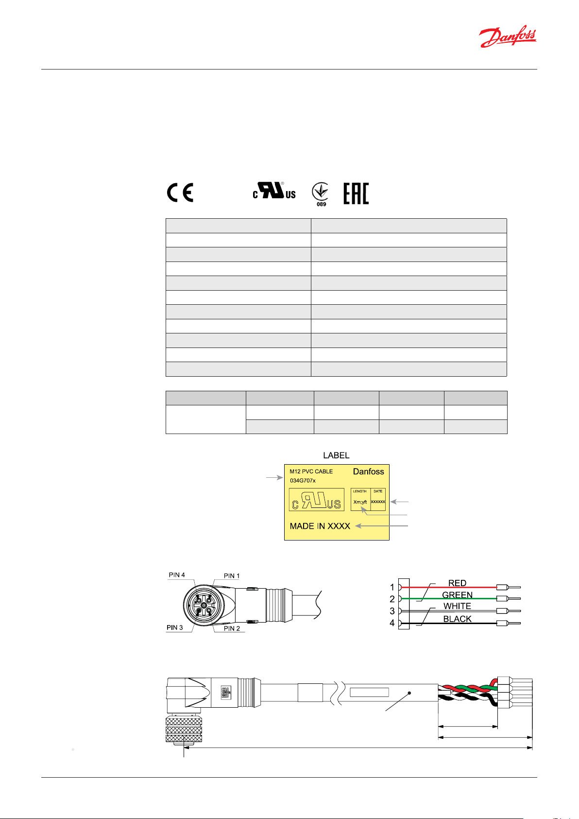
Accessories:
M12 angle cable
M12 angle female connector is intended for use with a standard M12 male connector,
available on stepper motor valves.
This cable is designed to offer high flexibility and small outer diameters with tensile strength.
The angle way M12 cable consist of paired, twisted wires, which decreases mutual influence between
signals transmitted along the cable and reduces influence of external sources of interference. The
cables thus provides a higher degree of protection against lost steps compared to other cables.
Approvals
Specification
Ordering
Identification
RoHS
Jacket PVC - black
Cable outer sheath Oil - resistant
Water proof rating IP 67
Operating temperature range -40 – +80 °C
Wire type Twisted pair, cross section 20 AWG / 0.5 mm2
Cable outer diameter 7.0 mm
Minimum bending radius 10 x cable diameter
Cable combustibility / test Flame retardant / VW-1 / CSA FT - 1
M12 standard EN 61076-2-101
Reference standard UL style 2464 and DIN VDE 0812
LVD directive 73/23/EEC and 93/68/EEC
Cable Cable length (L) Insulation Packing format Code no.
PVC - black
2 m / 6.6 ft SR-PVC Single pack 034G7073
8 m / 26.2 ft SR-PVC Single pack 034G7074
oduct type
ode no
Connections
Dimensions
A2 black
A1 white
B1 red
B2 green
34G210.10
8 meters / 26.2 feet
Manufacturing date
Meters / Feets
Country
34G209.10
Ø 63 mm / 1/4 inch
35 mm / 1.4 inch2 meters / 6.6 feet
49 mm / 1.9 inch
© Danfoss | DCS (sw) | 1017.10
DKRCC.PD.VC1.C7.02 | 4
Page 5
Danfoss
34G212.10
A
B
Data sheet | Electric regulating valve type KVS 15 – KVS 42
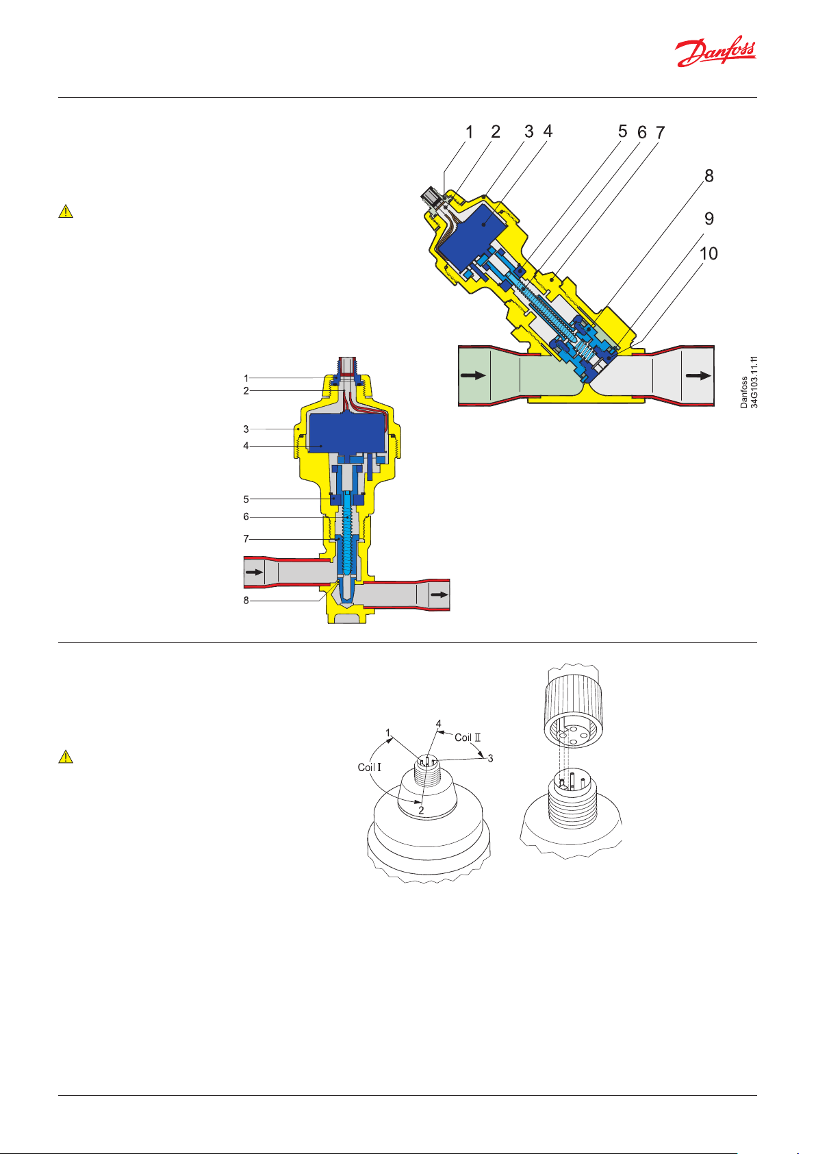
Design
Note:
Flow direction from A to B
refers the normal flow.
KVS 42
1. M12 Connector
2. Glass seal
3. AST motor housing
4. Stepper motor
5. Bearing
6. Spindle
7. Top nut
8. Valve piston
9. Valve seat
10. Valve cone
Danfoss
34G45.12.10
A
B
KVS 15
1. M12 connection
2. Glass seal
3. AST motor housing
4. Stepper motor
5. Bearing
6. Spindle
7. Cone and lead nut
8. Valve seat
Electrical wiring
Note:
Electrical check of
stepper motor and
wiring: coil I = 52 ohm
coil II = 52 ohm
© Danfoss | DCS (sw) | 1017.10
DKRCC.PD.VC1.C7.02 | 5
Page 6
Data sheet | Electric regulating valve type KVS 15 – KVS 42
Stepper motor switch
sequence
Valve application
Coil I Coil II
Red Green White Black
↑ CLOSING ↑
STEP
1 + - + 2 + - - +
3 - + - +
4 - + + 1 + - + -
If the controller driving the KVS valve is from
another manufacturer than Danfoss or a custom
design, the following points must be considered
in order to overcome potential step loss.
a. To ensure total closing of the valve, the controller should have a function to overdrive the
valve in the closing direction. It is recommended
to overdrive ten percent of the full step range at
appropriate intervals.
↓ OPENING ↓
b. The amount of lost steps may increase as a
function of the amount of changes of the opening degree. Such designed controller should be
able to compensate the lost steps after a defined
number of changes in opening degree.
Warning:
At power failure the KVS valve will remain in the
opening position it has at the moment of power
failure, unless a safety device in the form of a battery backup is installed.
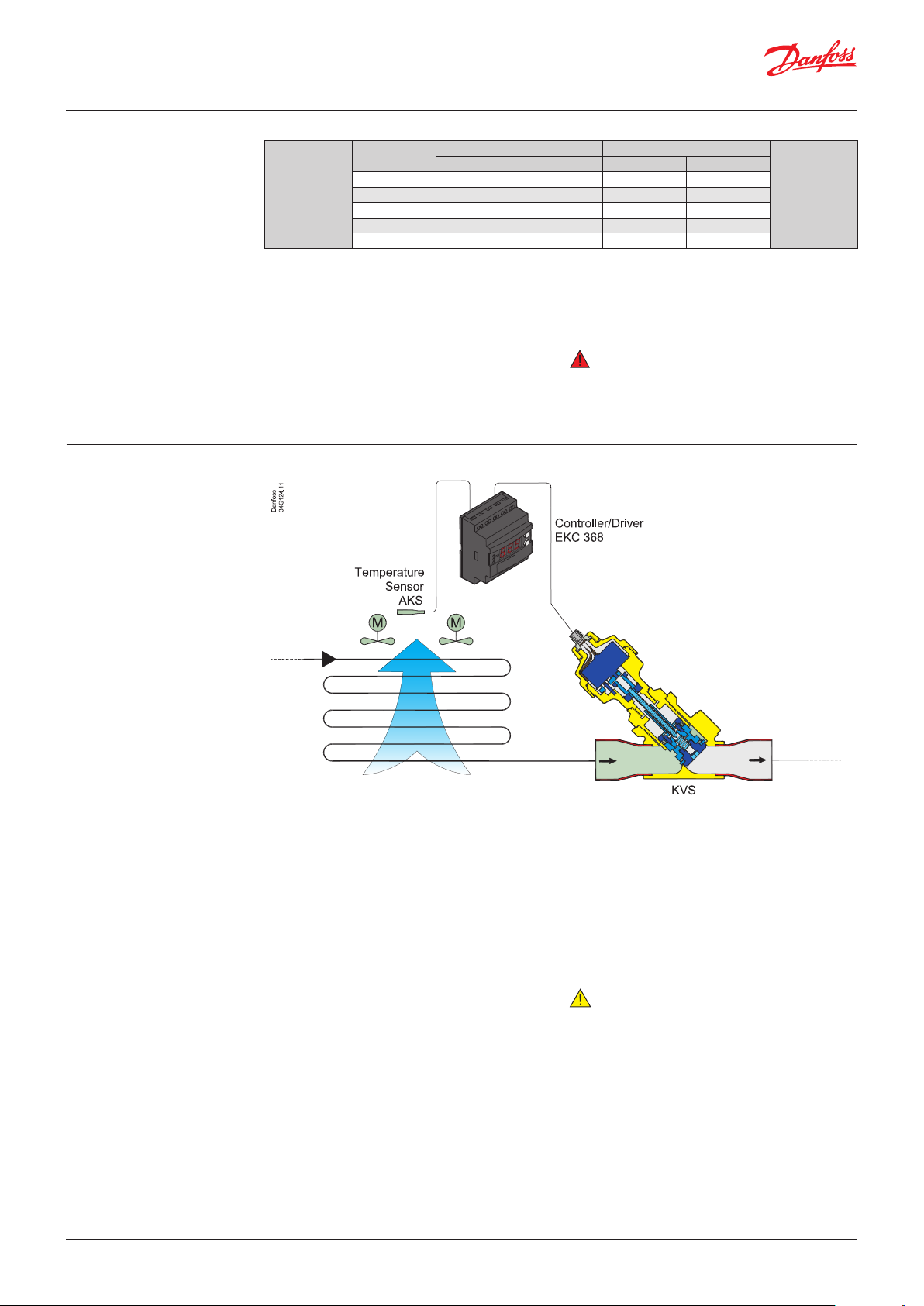
Evaporator
Valve operation The KVS valves operate modulating by electroni-
cally controlled activation of the AST stepper
motor. The motor is a type 2-phase bipolar,
which stays in position, unless power pulses from
a driver initiate the two discrete sets of motor
stator windings for rotation in either directions.
The direction of the rotation of the spindle
depends on the phase relationship of the power
pulses. This is decisive for the travel of the piston.
The motor is operating the spindle, whose rotating movements are transformed into linear
motion by the transmission in the cage assembly.
The AST motor housing has an integrated M12
connector.
The KVS 42 valves have a pressure slide port
respectively exponential cone, combining the
best performance qualities at part load conditions as well as providing a zero-resistance at
maximum capacity.
The piston design is fully power balanced, giving
identical bi-flow performance capabilities and
nearby identical maximum capacities.
Closing the valve by overdriving, ensures that the
reference number in steps is always correct.
Operating the KVS series requires a controller
with either 12 V dc voltage drive (5.5 W) or using
chopper drive (100 mA RMS).
Danfoss EKC 368 in an example of a qualified
controller.
Note:
Cable length between driver and actuator
exceeding 10 m (30 feet) can set off self-induction with reduction in the transmitted power and
irregularity in the sequences as consequence.
This may result in loss of steps now and again or
more permanent inadequate power supply to
the step motor.
The driver circuit as well as the cable specifications are part of this interference.
Please contact Danfoss for further information
and possible countermeasures.
© Danfoss | DCS (sw) | 1017.10
DKRCC.PD.VC1.C7.02 | 6
Page 7
Data sheet | Electric regulating valve type KVS 15 – KVS 42
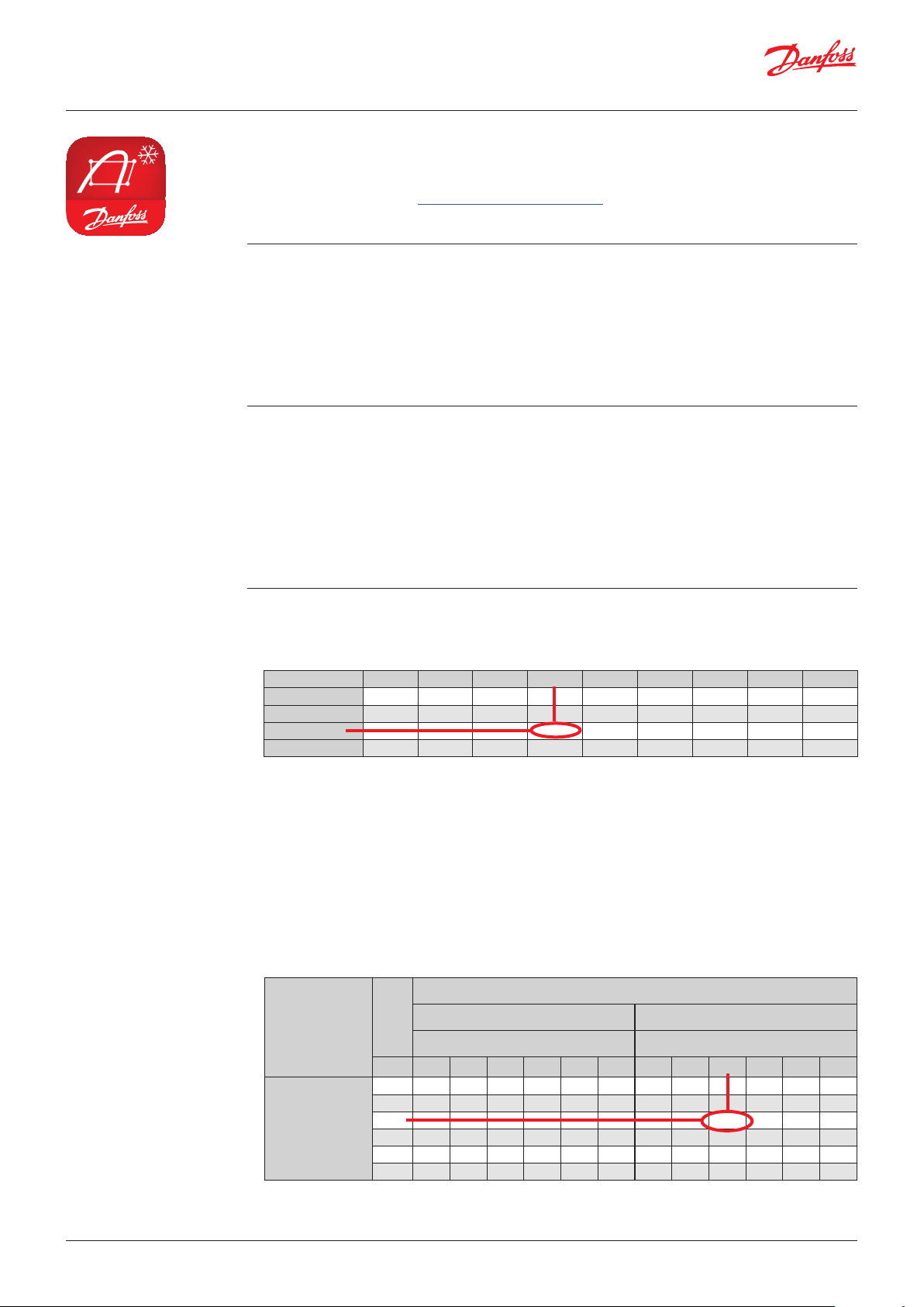
Coolselector2®
For easy and precise selection of valve, use Danfoss’ CoolSelector2® software. You can find the KVS
valves on the group, “Control and regulating valves”.
You can download it from http://coolselector.danfoss.com
Valve sizing For optimum performance, it is important to take
into consideration all system conditions and
requirements. Selection is also dependent on an
acceptable pressure drop across the valve.
The following information will be needed when
sizing a KVS valve:
Valve selection
Example
In valve selection it may be necessary to apply a
correction factor to the actual evaporator
capaity. This correction is required when system
conditions are different than table conditions.
Selection also depends on having an acceptable
pressure drop across the valve. The following
example illustrates correct sizing.
Step 1
Determine the correction factor for liquid temperature t
Correction factors for liquid temperature t
tl °C 10 15 20 25 30 35 40 45 50
R134 a 0.88 0.92 0.96 1.0 1.05 1.10 1.16 1.23 1.31
R22 0.90 0.93 0.96 1.0 1.05 1.10 1.13 1.18 1.24
R404A / R507 0.84 0.89 0.94 1.0 1.07 1.16 1.26 1.40 1.57
R407C 0.88 0.91 0.95 1.0 1.05 1.11 1.18 1.26 1.35
ahead of expansion valve.
l
l
• Refrigerant
• Evaporator capacity Qe in kW or TR
• Evaporating temperature te in °C or °F
• Liquid temperature ahead of expansion valve
tl in °C or °F
• Max. acceptable pressure drop in the KVS valve
in bar or psig
• Connection size
• Refrigerant: R 404A
• Evaporator capacity: Qe = 20 kW / 5.7 TR
• Evaporating temperature:
te = –10°C ~ 3.4 bar / 14°F ~ 49.3 psig
• Liquid temperature ahead of expansion valve:
t
= 25°C / 77°F
l
• Max. pressure drop in the valve:
∆p = 0.2 bar / 2.9 psig
• Connection type: Solder
• Connection size: 11/8 in.
From the correction factors table (see below) a
liquid temperature of 25°C / 100°F, R404A
corresponds to a factor of 1.0.
Step 2 Corrected evaporator capacity is
Qe = 20 × 1.0 = 20 kW / 5.7 × 1.0 = 5.7 TR
Step 3 Now select the appropriate capacity table,
R404A, and choose the column for an
evaporating temperature of te = –10°C / 14°F.
Using the corrected evaporator capacity, select a
valve that provides an equivalent or greater
capacity at an acceptable pressure drop across
the valve of 0.2 bar / 2.9 psig.
Rated Capacity (kW) SI units
t
e
Pressure drop ∆p [bar] Pressure drop ∆p [bar]
[°C] 0.05 0.1 0.2 0.3 0.5 0.7 0.05 0.1 0.2 0.3 0.5 0.7
10 3.30 4.65 6.52 7.93 10.1 11 .7 25.5 36.0 50.5 61.4 78.1 91.0
0 2.71 3.81 5.34 6.47 8 .18 9.46 21.0 29.6 41.4 50 .1 63.7 73.3
-10 2.20 3.09 4.30 5.19 6.49 7.4 3 17.0 23.9 33.3 40.2 50.3 57. 5
-20 1.75 2.45 3.39 4.06 5.00 5. 61 13. 6 19.0 26.3 31. 5 38.7 43.5
-30 1.37 1.91 2.60 3.08 3.67 3.97 10.6 14.8 20.2 23.9 28.5 30.8
-40 1.04 1.44 1.92 2.22 2.49 2.50 8.08 11.1 14.9 17. 2 19.3 19. 4
Step 4
R404A
KVS 42, 11/8 in.:
Single pack code no. 034G2850
KVS 42 delivers 33.32 kW / 9.5 TR at a 0.2 bar /
2.9 psig) pressure drop across the valve.
Based on the required connection size of 11/8 in,
the KVS 42 is the proper selection for this
example.
Rated capacity [kW]
KVS 15 KVS 42
© Danfoss | DCS (sw) | 1017.10
DKRCC.PD.VC1.C7.02 | 7
Page 8

Data sheet | Electric regulating valve type KVS 15 – KVS 42
Correction factor table
tl °C 10 15 20 25 30 35 40 45 50
R134 a 0.88 0.92 0.96 1. 0 1.05 1.10 1.16 1. 23 1. 31
R22 0.90 0.93 0.96 1.0 1.05 1.10 1.13 1.18 1. 24
R404A / R507 0.84 0.89 0.94 1.0 1.07 1.16 1.26 1.40 1.57
R407C 0.88 0.91 0.95 1.0 1.0 5 1.11 1.18 1.26 1.35
SI units
Capacities
Rated Capacity (kW)
t
e
[°C]
0.05 0.1 0.2 0.3 0.5 0.7 0.05 0.1 0.2 0.3 0.5 0.7
10 2.94 4.12 5.73 6.91 8.62 9.84 22.75 31.92 44.43 53.54 66.82 76.28
R134a
R404A
R407C
R22
* The valves in the capacity table refer to the evaporator capacity and based on liquid temperature
* The conditions printed are the most common for the different refrigerants.
* The pressure drop across the valve is assumed to be the difference between evaporation pressure and suction pressure.
1
) The capacity of vapour flow will not increase for pressure drops above the critical pressure drop.
0 2.38 3.33 4.60 5.50 6.75 7.56 18.46 25.81 35.67 42.65 52.32 58.56
-10 1.90 2.64 3.61 4.26 5.07 5.46 14.72 20.47 27.96 33.00 39.27 42.29
-20 1.48 2.05 2.74 3.15 3.52 3.551) 11.50 15.85 21.20 24.42 27.30 27.47
10 3.30 4.65 6.52 7.93 10.08 11.74 25.54 35.99 50.53 61.43 78.11 91.00
0 2.71 3.81 5.34 6.47 8.18 9.46 21.01 29.56 41.37 50.14 63.35 73.30
-10 2.20 3.09 4.30 5.19 6.49 7.43 17.03 23.91 33.32 40.20 50.28 57.54
-20 1.75 2.45 3.39 4.06 5.00 5.61 13.58 19.00 26.29 31.47 38.72 43.47
-30 1.37 1.91 2.60 3.08 3.67 3.97 10.61 14.76 20.18 23.85 28.47 30.78
-40 1.04 1.44 1.92 2.22 2.49 2.501)
10 3.58 5.04 7.06 8.56 10.84 12.57 27.73 39.04 54.69 66.34 83.98 97.37
0 2.94 4.14 5.77 6.97 8.74 10.03 22.81 32.05 44.71 54.01 67.74 77.75
-10 2.39 3.34 4.63 5.55 6.86 7.74 18.48 25.88 35.87 43.03 53.14 59.94
-20 1.90 2.64 3.62 4.29 5.16 5.62 14.70 20.48 28.07 33.26 39.96 43.56
10 3.74 5.26 7.38 8.96 11.36 13.19 28.95 40.76 57.16 69.40 88.01 102.22
0 3.14 4.41 6.16 7.45 9.38 10.80 24.30 34.16 47.73 57.74 72.66 83.70
-10 2.60 3.64 5.06 6.09 7.57 8.60 20.12 28.21 39.21 47.17 58.63 66.60
-20 2.12 2.96 4.07 4.85 5.90 6.54 16.40 22.90 31.55 37.59 45.75 50.67
-30 1.69 2.35 3.18 3.73 4.36 4.57 13.10 18.18 24.68 28.92 33.79 35.44
-40 1.32 1.81 2.39 2.71 2.891) x1) 10.23 14.02 18.52 20.99 22.371) x1)
tl=30°C, superheat= sub cooling = 0 K.
Other conditions can be calculated with Danfoss calculation software CoolSelector®
KVS15 KVS 42
Pressure drop ∆p [bar] Pressure drop ∆p [bar]
8.08 11.14 14.91 17.20 19.26 19.391)
1)
© Danfoss | DCS (sw) | 1017.10
DKRCC.PD.VC1.C7.02 | 8
Page 9
Data sheet | Electric regulating valve type KVS 15 – KVS 42
Correction factor table
tl °F 50 60 70 80 90 100 110 120
R134 a 0.79 0.82 0.86 0.90 0.95 1. 0 1.06 1.13
R22 0.82 0.85 0.88 0.92 0.96 1.0 1.05 1.10
R404A / R507 0.71 0.75 0.80 0.85 0.92 1. 0 1.10 1.24
R407C 0.78 0.81 0.85 0.89 0.94 1.0 1. 07 1.15
US units
Capacities
Rated Capacity (TR)
(TR) = ton of refrigerants
t
e
[°F]
0.7 1.5 3 5 7 10 0.7 1.5 3 5 7 10
50 0.86 1.25 1.73 2.19 2.53 2.91 6.65 9.66 13.44 16.96 19.60 22.58
R134a
R404A
R407C
* The valves in the capacity table refer to the evaporator capacity and based on liquid temperature
* The conditions printed are the most common for the different refrigerants.
* The pressure drop across the valve is assumed to be the difference between evaporation pressure and suction pressure.
1
) The capacity of vapour flow will not increase for pressure drops above the critical pressure drop.
30 0.68 0.98 1.36 1.69 1.93 2.17 5.28 7.63 10.53 13.12 14.96 16.83
10 0.53 0.76 1.03 1.26 1.40 1.49 4.10 5.88 7.99 9.74 10.82 11.58
-5 0.43 0.61 0.82 0.96 1.03 1.031) 3.34 4.74 6.32 7.46 7.95 8.011)
50 0.98 1.43 2.00 2.56 3.00 3.53 7.59 11.06 15.53 19.84 23.23 27.33
30 0.79 1.15 1.61 2.04 2.38 2.78 6.12 8.90 12.45 15.83 18.45 21.52
10 0.63 0.91 1.26 1.59 1.84 2.12 4.85 7.03 9.78 12.34 14.26 16.41
-5 0.52 0.75 1.04 1.29 1.48 1.67 4.01 5.81 8.02 10.03 11.47 12.97
-20 0.42 0.61 0.83 1.03 1.15 1.26 3.28 4.72 6.46 7.95 8.94 9.80
-40 0.32 0.45 0.60 0.71 0.76 0.771) 2.44 3.47 4.64 5.50 5.89 5.951)
50 1.05 1.53 2.14 2.72 3.18 3.72 8.12 11.82 16.55 21.09 24.62 28.81
30 0.84 1.23 1.71 2.16 2.50 2.90 6.54 9.50 13.24 16.75 19.40 22.44
10 0.67 0.96 1.33 1.67 1.91 2.16 5.17 7.47 10.33 12.91 14.77 16.71
-5 0.55 0.79 1.08 1.33 1.50 1.64 4.26 6.14 8.40 10.34 11.62 12.73
50 1.08 1.58 2.21 2.82 3.30 3.87 8.40 12.24 17.16 21.88 25.58 29.99
30 0.89 1.30 1.81 2.30 2.67 3.10 6.92 10.06 14.04 17.80 20.68 24.01
10 0.72 1.05 1.45 1.82 2.10 2.39 5.60 8.11 11.25 14.13 16.24 18.54
R22
-5 0.61 0.88 1.21 1.50 1.70 1.90 4.72 6.81 9.36 11.62 13.18 14.69
-20 0.51 0.73 0.99 1.20 1.33 1.42 3.92 5.62 7.64 9.30 10.31 10.99
-40 0.39 0.54 0.72 0.83 0.861) x1) 2.98 4.22 5.56 6.43 6.641) x1)
tl=86°F, superheat= sub cooling = 0 K.
Other conditions can be calculated with Danfoss calculation software CoolSelector®
KVS15 KVS 42
Pressure drop ∆p [psi] Pressure drop ∆p [psi]
© Danfoss | DCS (sw) | 1017.10
DKRCC.PD.VC1.C7.02 | 9
Page 10

Dimensions and weights
KVS 15
Type
KVS 15
KVS 42
Type
KVS 42
Connections H
ODF x ODF (A x B)
[in] [mm]
5
/8 × 5/816 × 16
7
/8 × 7/822 × 22
Connections H
ODF x ODF (A x B)
[in] [mm]
7
/8 × 7/822 × 22 4.8 12 0 7. 4 188 .5 5.6 143 3.7 93 3.8 95.5 2.4 60 0.95 24 1.9 4.2
1
[in] [mm] [in] [mm] [in] [mm] [in] [mm] [in] [mm] [in] [mm] [in] [mm] [kg] [lb.]
1.2 30 0.5 13 2.5 64 5.9 159 2.4 60 2.4 60 2.4 60 0.7 1.5
1
[in] [mm] [in] [mm] [in] [mm] [in] [mm] [in] [mm] [in] [mm] [in] [mm] [kg] [lb.]
H
2
L
1
H
3
L
2
Danfoss
34G102.13
H
4
L
3
L
1
B
L
4
øD
L
2
øD
1
Weight
A
1
B
1
Weight
11/8 × 11/828 × 28 4.8 12 0 6.7 168.5 5.6 143.0 3.3 83.0 3.4 85.5 2.4 60 0.95 24 1.9 4.2
13/8 × 13/835 × 35 4.8 120 7. 0 178 .5 5.6 143.0 3.5 88.0 3.6 90.5 2.4 60 0.95 24 1.9 4.2
15/8 × 15/
- 4.8 120 7.4 188 .5 5.6 143.0 3.7 93.0 3.8 95.5 2.4 60 0.95 24 1.9 4.2
8
Related products
EKD 316 driver EKC 368 controller AKS 11 / AKS 12 temperature sensor
AKS pressure transmitter
© Danfoss | DCS (sw) | 2017.10
Code no. 034G0013
AST-G service driver
DKRCC.PD.VC1.C7.02 | 10
 Loading...