

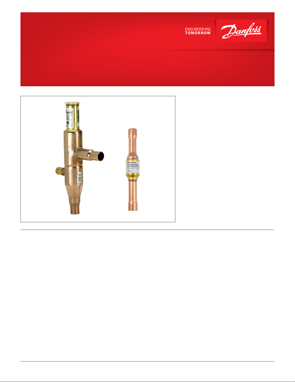
Data sheet
Condensing pressure regulator, type KVR
Differential pressure valve, type NRD
The condensing pressure regulator, type KVR can
be mounted in either the gas or liquid side of the
condenser in refrigeration and air conditioning
systems.
They are used to maintain a constant and
sufficiently high condensing pressure with systems
using air-cooled condensers.
They can also be used with valve types NRD
or KVD to assure that adequate pressure is
maintained on the receiver.
Features • Accurate, adjustable pressure regulation
• Wide capacity and operating range
• Pulsation damping design
• Stainless steel bellows
• Compact angle design for easy
installation in any position
• “Hermetic” brazed construction
• ¼ in. Schrader valve for pressure
gauge connection
© Danfoss | DCS (rja) | 2020.07
• Available with flare or ODF solder connections
• Can be used as a relief valve from high pressure
to suction side
• KVR 12 - KVR 22 and NRD: May be used in the
following EX range: Category 3 (Zone 2)
AI197786435007en-000401 | 1
Data sheet
|
Condensing pressure regulator, type KVR and differential pressure valve, type NRD
Approvals UL LISTED, file SA7200
EAC
Technical data
Metric conversions
1 psi = 0.07 bar
5
⁄9 (t1 °F -32) = t2 °C
R22, R32**, R134a, R290*, R404A, R407A, R407C, R407F, R407H,
R410A**, R448A, R449A, R449B, R450A, R452A, R452B**, R454A*,
R454B**, R454C*, R455A*, R507, R513A, R515B, R516A, R600*, R600a*,
Refrigerants
R1233zd (E) **, R123 4ze (E)*, R 1234 y f*, R 1270*
KVR 12 – KVR 22 only; see more details in the note below the table
**NRD only
HCFC and non-flammable HFC: KVR 28 – KVR 35
Regulation range
Maximum working pressure
Maximum test pressure
Pe = 73.00 – 254.00 psig
Factory setting = 145 psig
KVR: PS/MWP = 406 psig
NRD: PS/MWP = 667 psig
KVR: Pe = 450 psig
NRD: Pe = 870 psig
Medium temperature range KVR: - 49 – 266 °F
P band (full valve stroke)
Opening differential pressure for NRD
This product (KVR 12 - KVR 22) is evaluated for R290, R454A,
R454C, R455A, R600, R600a, R1234ze(E), R1234yf, R1270 by ignition
source assessment in accordance with standard EN ISO80079-36.
KVR 12 – KVR 22: 90 psi
KVR 28 – KVR 35: 72.5 psi
Start opening: Δp= 20 psi
Fully open: Δp = 43 psi
For complete list of approved refrigerants,
visit http://store.danfoss.com/ and search for individual code
numbers, where refrigerants are listed as part of technical data.
Flare connections are only approved for A1 and A2L refrigerants.
NRD is evaluated for R32, R290, R452B, R454A, R454B, R454C
R455A, R600, R600a, R1233zd(E), R1234ze(E), R1234yf, R1270
by ignition source assessment in accordance with standard EN
ISO80079-36.
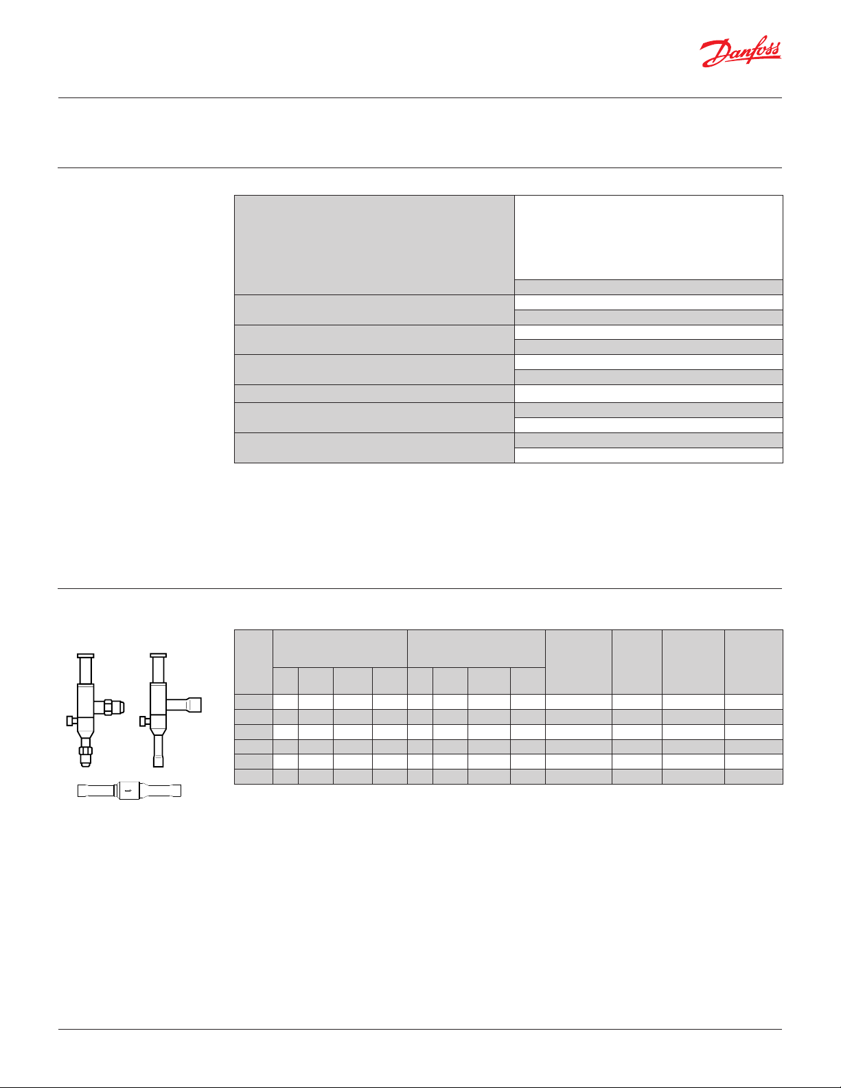
Ordering KVR 12, KVR 15, KVR 22, KVR 28, KVR 35, NRD
Rated liquid capacity 1)
(Evaporator capacity)
Typ e
R22 R134 a
[TR]
R404A/
R507
R407C R22 R13 4a
KV R 12 12. 7 11. 8 8.2 13.8 4.13 3.03 3.27 4.50
KV R 15 12.7 11. 8 8.2 13 .8 4 .13 3.03 3.27 4.50
KVR 22 12.7 11. 8 8.2 13 .8 4.13 3.03 3.27 4.50 – –
KVR 28 32.6 30.2 20.9 35. 5 10.93 8.04 8.66 11. 91 – – 1 1/
KVR 35 32.6 30.2 20.9 35.5 10.93 8.04 8.66 11. 91 – – 1 3/
NRD – – – – – – – – – –
The connection dimensions chosen must not be too small, as gas velocities in excess of 130 ft/s at the inlet of the regulator can result
in flow noise.
1
) Rated capacity is based on:
– evaporating temperature te = 40 °F
– condensing temperature tc = 110 °F
– pressure drop across the valve
Δp = 3 psi for liquid capacity
Δp = 6 psi for hot gas capacity
2
) KVR are delivered without flare nuts. Separate flare nuts can be delivered:
– 1⁄2 in. code no. 011L1103
– 5⁄8 in. code no. 011L1167
Rated hot gas 1)
(Evaporator capacity)
[TR]
R404A/
R507
Flare
connection 2)
Code no.
Solder
connection
R407C [in.] [in.]
1
2
/
5
034L 0091
8
/
034L0 092
1
5
7
1
Code no.
2
/
034L00 93
8
/
034L0097
8
/
034L0094
8
034L0095
8
034 L0100
2
/
02 0-11 32
© Danfoss | DCS (rja) | 2020.07
AI197786435007en-000401 | 2
Data sheet
|
Condensing pressure regulator, type KVR and differential pressure valve, type NRD
Liquid capacity
Metric conversions
1 psi = 0.07 bar
5
⁄9 (t1 °F -32) = t2 °C
1 TR = 3.5 kW
1 in. = 25.4 mm
Max. regulator capacity Qe 1)
Liquid capacity [TR]
Typ e
temperature t
c
[°F] 1.5 3 6 10 25 1.5 3 6 10 25
Condensing
50 13.1 17. 6 25.2 32.9 52.6 1.81 2.47 3.52 4.51 6.86
KVR 12
KVR 15
KVR 22
70 11.9 16.0 23.0 30.0 48.0 1.92 2.62 3.75 4.83 7. 44
90 10.6 14. 4 20.8 27.0 43.2 2.04 2.76 3.96 5.12 7.9 4
110 9.2 12.7 18.4 23.9 38.2 2.13 2.89 4.13 5.36 8.34
130 7. 8 11.0 16.0 20.7 33.1 2.20 2.98 4.27 5.54 8.64
50 33.5 45.0 64.4 84.2 134 .6 4.77 6.50 9.31 11 . 9 5 18 .15
KVR 28
KVR 35
70 30.4 41.1 58.9 76.8 12 2.8 5.11 6.93 9.92 12.79 19.66
90 2 7.1 37. 0 53.2 69.2 110. 6 5.42 7. 3 4 10 .4 8 13. 54 20.98
110 23.6 32.6 47. 2 61.3 97. 8 5.67 7. 65 10 .93 14.16 22.06
130 20.0 28.0 40.9 53.0 84.6 5.79 7.83 11. 23 14. 60 22.85
50 12.0 16 .9 24 .0 31.0 49.1 1.40 1.97 2.75 3.50 5.15
KVR 12
KVR 15
KVR 22
70 11.9 16.0 23.0 30.0 48.0 1.92 2.62 3.75 4.83 7. 44
90 9.6 13. 6 19.2 24.8 39.3 1. 50 2.12 2.97 3.80 5.75
110 8.4 11. 8 16.7 21.6 34.2 1.53 2.15 3.03 3.87 5.92
130 7.1 10.0 14. 2 18.3 29.0 1.52 2.14 3.01 3.86 5.95
50 30.7 43.4 61. 3 79.2 126.0 3.72 5.24 7. 31 9.26 13. 60
KVR 28
KVR 35
70 27. 6 39.1 55.3 71.4 113. 0 3.87 5.44 7.63 9.71 14.49
90 24.5 34.7 49.1 63.4 100.0 3.99 5.62 7.8 9 10.07 15. 22
110 21.4 30.2 42.8 55.3 8 7.5 4.06 5.71 8.04 10.28 15.69
130 18.1 25.6 36.3 46.9 74 . 2 4.03 5.68 8.00 10.25 15. 77
1
) The capacities are based on:
– Evaporating temperature te= 40 °F.
– For other evaporating temperatures see table below
(Evaporator capacity)
Offset 45 psi Offset 45 psi
Pressure drop ∆p [psi] Pressure drop ∆p [psi]
Hot gas capacity [TR]
(Evaporator capacity)
R22 R22
R134 a R134 a
© Danfoss | DCS (rja) | 2020.07
Correction factors for evaporating temperature t
t
e
[°F]
R22
R134a
System capacity x correction factor = table capacity.
-40 -30 -20 -10 0 10
1.12 1.09 1.05 1.03 1.0 0.98
1.22 1.16 1.10 1.04 1.0 0.96
e
AI197786435007en-000401 | 3

Data sheet
|
Condensing pressure regulator, type KVR and differential pressure valve, type NRD
Liquid capacity
Metric conversions
1 psi = 0.07 bar
5
/9 (t1 °F -32) = t2 °C
1 TR = 3.5 kW
1 in. = 25.4 mm
Max. regulator capacity Qe 1)
Liquid capacity [TR]
Condensing
Typ e
KV R 12
KV R 15
KVR 22
KVR 28
KVR 35
KV R 12
KV R 15
KVR 22
KVR 28
KVR 35
1
) The capacities are based on:
Evaporating temperature te= 40 °F.
For other evaporating temperatures see table below.
temperature t
c
[°F] 1.5 3 6 10 25 1.5 3 6 10 25
50 9.2 12 .4 17. 6 23.0 37. 0 1. 63 2.09 2.99 3.84 5.87
70 8 .1 10.9 15. 7 20.4 32.7 1.60 2 .17 3.10 4.00 6.17
90 7. 0 9.6 13. 8 17.9 28.7 1.65 2.25 3.21 4 .15 6.45
110 5.9 8.2 11. 8 15. 4 24. 5 1.68 2.28 3.27 4.24 6.60
130 4.8 6.8 10.0 13.0 20.6 1. 69 2.31 3.34 4.34 6.78
50 23.6 31. 7 45.2 59.0 94.5 4.06 5.52 7.89 10.15 15 .48
70 20.8 27. 9 40 .1 52.2 83.6 4 .24 5.74 8.20 10.58 16. 32
90 17.9 24.5 35.2 45.9 73.4 4.41 5.96 8.50 10.99 17.06
110 15.1 20.9 30.3 39. 3 62.7 4.88 6.06 8.66 11 .2 2 17. 49
130 12.3 17. 4 25.7 33 .1 52.7 4.49 6.12 8.82 11. 45 17. 92
50 4.2 19. 0 27. 2 35.5 56.8 1.96 2.67 3.80 4. 87 7. 41
70 12 .9 17. 3 24.8 32.4 51. 8 2.07 2.83 4.05 5.22 8.04
90 11. 5 15 .6 22.5 29.2 46.7 2.20 2.98 4.28 5.53 8.58
110 10.0 13 .8 20.1 26.1 41.6 2.32 3 .15 4.50 5.84 9.09
130 8.6 12.1 17.6 22.8 36.4 2.42 3.28 4.70 6.09 9.50
50 36.2 48.6 69.6 90.9 145.4 5.15 7.02 10. 06 12.91 19 .60
70 32. 8 44.4 63.6 82.9 132. 6 5.52 7. 4 8 10.71 13. 81 21.2 3
90 29.3 40.0 57. 5 74.7 119. 5 5.85 7.9 3 11. 32 16.62 22.66
110 25.7 35.5 51.5 66.8 106.6 6 .18 8.34 11.9 1 15 .43 24.05
130 22.0 30.8 45.0 58.3 93.1 6.37 8.61 12. 35 16.06 2 5.14
(Evaporator capacity)
Offset 45 psi Offset 45 psi
Pressure drop ∆p [psi] Pressure drop ∆p [psi]
Hot gas capacity [TR]
(Evaporator capacity)
R404A/R507 R404A/R507
R407C R407C
Correction factors (evaporating temperature)
e
t
[°F]
R404A / R507 1.32 1.22 1.14 1.06 1.0 0.95
R407C 1.20 1.15 1.09 1.0 4 1.0 0.96
System capacity x correction factor = table capacity.
-40 -20 0 20 40 50
© Danfoss | DCS (rja) | 2020.07
AI197786435007en-000401 | 4

Data sheet
|
Condensing pressure regulator, type KVR and differential pressure valve, type NRD
Sizing
Valve selection
For optimum performance, it is important to select
a KVR valve according to system conditions and
application.
Example
When selecting the appropriate valve it may be
necessary to convert the actual evaporator capacity
using a correction factors. This is required when
your system conditions are different than the table
conditions.
The selection is also dependant on the acceptable
pressure drop across the valve.
The following example illustrates how this is done.
Application example
Liquid capacity application
• The following data must be used when sizing
• a KVR valve:
• Refrigerant: HCFC, HFC and HC: KVR 12 – KVR 22,
HCFC and non-flammable HFC: KVR 28 – KVR 35
• Evaporator capacity Qe in [TR]
• Evaporating temperature te in [°F]
• Condensing temperature tc in [°F]
• Connection type: flare or solder
• Connection size in [in.]
KVR in a liquid capacity application
• Refrigerant: R22 example
• Evaporator capacity: Qe= 28.7 TR
• Evaporating temperature: te= -40 °F ~ 21 psig
• Condensing temperature: tc= 90 °F ~ 170 psig
• Connection type: Solder
• Connection size: 5⁄8 in.
© Danfoss | DCS (rja) | 2020.07
Application example
Hot gas capacity application
AI197786435007en-000401 | 5

Data sheet
|
Condensing pressure regulator, type KVR and differential pressure valve, type NRD
Valve selection
(continued)
Step 1
Determine the correction factor for evaporating
temperature te.
From the correction factors table an evaporating
temperature of -40 °F, R22 corresponds to
a factor of 1.12.
Correction factors
t
e
[°F]
R22 1.12 1.09 1.05 1.03 1.0 0.98
R134a 1.22 1.16 1.10 1.04 1.0 0.96
R404A, R507 1.32 1.22 1.14 1.06 1.0 0.95
R407C 1.20 1.15 1.09 1.04 1.0 0.96
Plant capacity x correction factor = table capacity
-40 -30 -20 -10 0 10
Step 2
Corrected evaporator capacity is
Qe = 28.7 x 1.12 = 32.14 TR
Step 3
Now select the appropriate capacity table and
choose the line for a condensing temperature
tc= 90 °F.
Using the corrected evaporator capacity, select a
valve that provides an equivalent or greater
KVR 12, KVR 15, KVR 22 delivers 38.2 TR
at a 25 psi pressure drop across the valve.
Based on the required connection size of
5
⁄8 in. ODF, the KVR 15 is the proper selection
for this example.
capacity at an acceptable pressure drop.
Step 4
KVR 15, 5⁄8 in. solder connection:
code no. 034L0097
© Danfoss | DCS (rja) | 2020.07
AI197786435007en-000401 | 6

21
Data sheet
|
Condensing pressure regulator, type KVR and differential pressure valve, type NRD
Design / Function KVR NRD
1. Seal cap
2. Gasket
3. Setting screw
4. Main spring
5. Valve body
6. Equalizing bellows
7. Valve plate
8. Valve seat
9. Damping device
10. Pressure gauge connection
11. Cap
12. Gasket
13. Insert
14. Piston
15. Valve plate
16. Piston guide
17. Valve body
18. Spring
1
= 5⁄16 in.
2
3
4
5
6
7
8
9
10
11
12
13
The condensing pressure regulator, type KVR
opens upon a rise in pressure on the inlet side, i.e.
when the pressure in the condenser reaches the set
value. KVR regulates on the inlet pressure only.
Pressure variations on the outlet side of the
regulator do not affect the degree of opening, as
the valve is equipped with equalization bellows (6).
The bellows has an effective area corresponding to
that of the valve seat neutralizing any changes to
the setting.
14
15
16
17
18
19
20
The valve is also equipped with a damping device
(9) providing protection against pulsations which
can normally arise in a refrigeration system.
The damping device helps to ensure long life
for the regulator without impairing regulation
accuracy.
Differential valve type NRD begins to open when
the pressure drop in the valve is 20 psig.
© Danfoss | DCS (rja) | 2020.07
AI197786435007en-000401 | 7

Data sheet
|
Condensing pressure regulator, type KVR and differential pressure valve, type NRD
P-band and Offset Principle diagram
Capacity
100%
75%
50%
25%
Setting
Metric conversions
1 psi = 0.07 bar
5
⁄9 (t1°F -32) = t2 °C
Proportional band
The proportional band or P-band is defined as
the amount of pressure required to move the
valve plate from closed (set point) to fully open
position.
Example
If the valve is set to open at 120 psig and the
valve P-band is 90 psi, the valve will give maximum
capacity when the inlet pressure reaches 210 psig.
[psi]
Offset
P-band
Offset
The offset is defined as the permissible pressure
variation in condenser pressure (temperature). It is
calculated as the difference between the required
working pressure and the minimum allowable
pressure. The offset is always a part of the P-band.
Example with R22
A working temperature of 110 °F ~ 230 psig is
required, and the temperature must not drop
below 100 °C ~ 200 psig (set point).
The offset will then be 30 psi.
© Danfoss | DCS (rja) | 2020.07
AI197786435007en-000401 | 8

Danfoss can accept no responsibility for possible errors in catalogues, brochures and other printed material. Danfoss reserves the right to alter its products without notice. This also applies to products
already on order pro
All trademarks in this material are property of the respec
Dimensions and weights KVR NRD
L
D
Metric conversions
1 in. = 25.4 mm
1 lb = 0.454 kg
Connection
Typ e
KV R 12
KV R 15
Flare
1
/
5
/
Solder
ODF
2
8
KVR 22 –
KVR 28 – 1 1/
KVR 35 – 1 3/
NRD –
øD
L1
Net weight
[kg]
L1
NV1NV2H1H2H
1
/20.748 0. 748 7.0 45 3.898 2.598 – – 2.520 1.614 0. 394 1.181 0.88
5
/80.945 0.945 7.0 45 3.898 2. 598 – – 2.520 1.614 0.472 1.181 0.88
7
8
/
– – 7. 045 3.898 2.598 – – 2.520 1.614 0.669 1.181 0.88
8
– – 10 .197 5.945 4. 055 – – 4.13 4 1.890 0.787 1.6 93 2.20
8
– – 10 .197 5.945 4. 055 – – 4.13 4 1.890 0.984 1.693 2.20
1
2
/
– – – – – 5.157 0.394 – – – 0.866 0.1
3
L L
1
1
B
C
2
B
Solder
vided that such alterations can be made without subsequential changes being necessary eady agreed.
© Danfoss | DCS (rja) | 2020.07
tive companies. Danfoss and the Danfoss logotype are trademarks of Danfoss A/S. All rights reserved.
AI197786435007en-000401 | 9
 Loading...