

Page 1
Installation Instructions
Fan Extension Cable
®
VLT
AutomationDrive FC 360
The instructions provide information about the replacement of
the fan extension cable for J6 and J7 enclosure types of the
®
AutomationDrive FC 360.
VLT
Only Danfoss-authorised, qualified personnel is allowed to
repair this equipment. The personnel must be familiar with the
instructions and safety measures described in the
®
AutomationDrive FC 360 Service Manual.
VLT
1.1.1 Items Supplied
Items supplied depend on ordered code number and
enclosure type of the frequency converter.
Code number Items supplied
132B0301
132B0320
Fan extension cable, J6
•
Fan extension cable, J7
•
1.1.2 Tools Required
Screwdrivers:
•
Flat-edged
-
T10
-
T20
-
T25
-
T30
-
N8 socket wrench
•
N10 socket wrench
•
N5 Allen key
•
1.1.3 Safety Instructions
WARNING
DISCHARGE TIME
The frequency converter contains DC-link capacitors, which
can remain charged even when the frequency converter is
not powered. Failure to wait the specified time after power
has been removed before performing service or repair work,
could result in death or serious injury.
1. Stop the motor.
2. Disconnect AC mains, permanent magnet type
motors, and remote DC-link power supplies,
including battery back-ups, UPS, and DC-link
connections to other frequency converters.
3. Wait for the capacitors to discharge fully, before
performing any service or repair work. The duration
of waiting time is specified in Table 1.1.
Minimum waiting time (minutes)
Voltage [V]
415
380-480 0.37-7.5 kW 11-75 kW
High voltage may be present even when the warning LEDs are off!
Table 1.1 Discharge Time
Danfoss A/S © Rev. 2014-03-04 All rights reserved. MI06N102
Page 2
1.1.4 Installation
Replacing Fan Extension Cable for J6
1.
Follow the instructions in VLT
360 Service Manual to remove control card cassette.
2. Disconnect the defective fan extension cable, and
connect a new cable. Illustration 1.1 shows the fan
extension cable connection point on the power
control card.
®
AutomationDrive FC
Replacing Fan Extension Cable for J7
1.
Follow the instructions in VLT
®
AutomationDrive FC
360 Service Manual to remove the front cover.
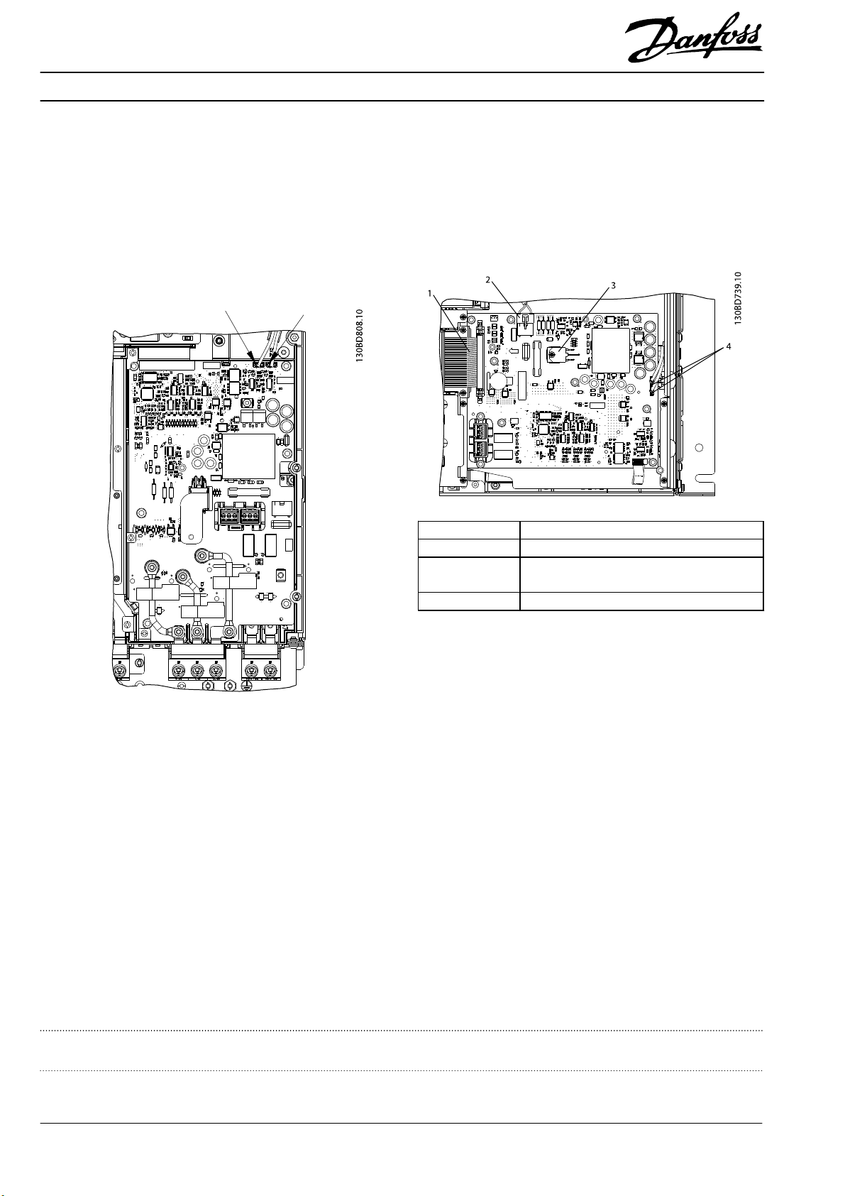
2. Disconnect the defective fan extension cable, and
connect a new cable. Illustration 1.2 shows the
connection point of fan extension cables on the
power control card.
1 44-pole cable
2 UDC bus cable
3 Screw (T10, M3x10), from MosFet transistor heat
sink
4 Fan extension cable connection point
Illustration 1.2 Power Control Card, Enclosure Type
3. Reinstall other unmounted components in reverse
Illustration 1.1 Connection Point of Fan Extension Cable on Power
Card
order.
3. Reinstall other unmounted components in reverse
order.
Danfoss can accept no responsibility for possible errors in catalogues, brochures and other printed material. Danfoss reserves the right to alter its products without notice. This also applies to products already on
order provided that such alterations can be made without subsequential changes being necessary in specifications already agreed. All trademarks in this material are property of the respective companies. Danfoss
and the Danfoss logotype are trademarks of Danfoss A/S. All rights reserved.
Danfoss A/S
Ulsnaes 1
DK-6300 Graasten
www.danfoss.com/drives
MI06N102132R0223 Rev. 2014-03-04
*MI06N102*
 Loading...