How it Works
Log In / Sign Up
Buy Points
How it Works
FAQ
Contact Us
Questions and Suggestions
Users
Danfoss
Loading...
E
EVUL
EVUL 1
3
EVUL 2
EVUL 3
EVUL 4
EVUL 5
EVUL 6
EVUL 8
3
EVUP 1.5
EVUP 2.7
EVН 2-6
EXD 316
3
EXP 203
3
EXP 204
3
EXP 205
3
EXP 206
3
EXP 403
3
EXP 404
EXP 405
3
EXP 406
3
EXP 802
3
EXP 803
3
EXP 804
3
EXP 805
3
EXP 806
2
Expansion Module
Explanation of safety symbols
Extended range
ExtensionBox
External Remote Charge Pressure Filter
EZ 106
EZ 111
EZ 115
EZF
EZ FC 321
3
F
F1
F2
F 74-90 cc
FA
FA 15
7
FA 20
7
FA 25
Fachmann
Fan Assembly
Fan-cooled non packaged condensing units
Fan Drive HIC
Fan Drive Motor
Fan Extension Cable
Fan Replacement
Fan Speed Controllers RGE
Fast TeleTeaching Mode
Fault Location
Fault Manager
FBA
FBH
3
FBH-Verteiler
FBH-xF
FC 051
FC 100
10
FC 101
31
FC 102
174
FC 103
76
FC103-110-250Kw
FC 111
8
FC 131
FC 200
52
FC 200 Series
FC202
161
FC 280
57
FC 300
52
FC 300 Interbus
FC 300 Profibus
2
FC 301
67
FC 302
204
FC 360
25
FC 361
8
FC 51
37
FC 51 Series
FCD 300
16
FCD 300 DeviceNet
FCD 302
20
FCH10-BD
FCM 10
2
FCM 106
13
FCM 300
17
FCM 300 PROFIBUS
FCM 300 Series
FCM305 56
FCM307 56
FCM311 143
FCM315 145
FCM322 182
FCM330 182
FCM340 184
FCM350 213
FCM375 215
FCP 106
19
FC Series Add-On
FED-FF
17
Få styr på afkølingen i din varmtvandsbeholder
Loading...
Loading...
Nothing found
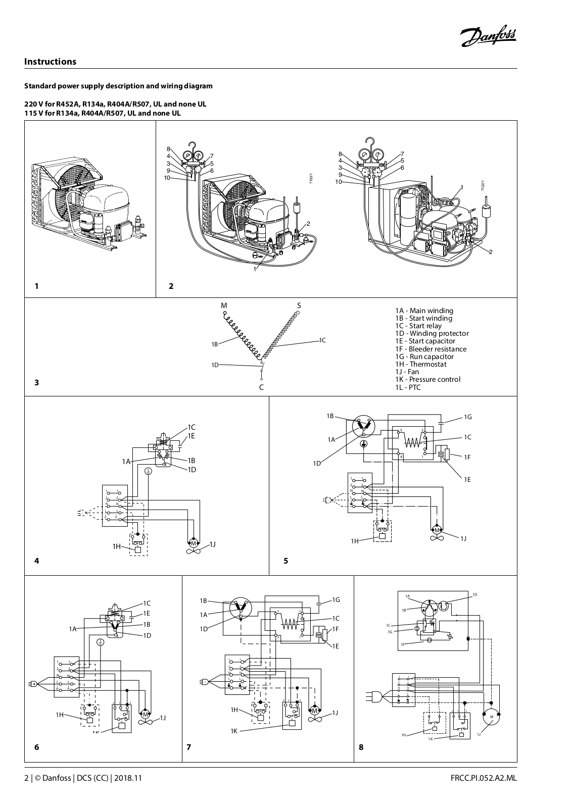
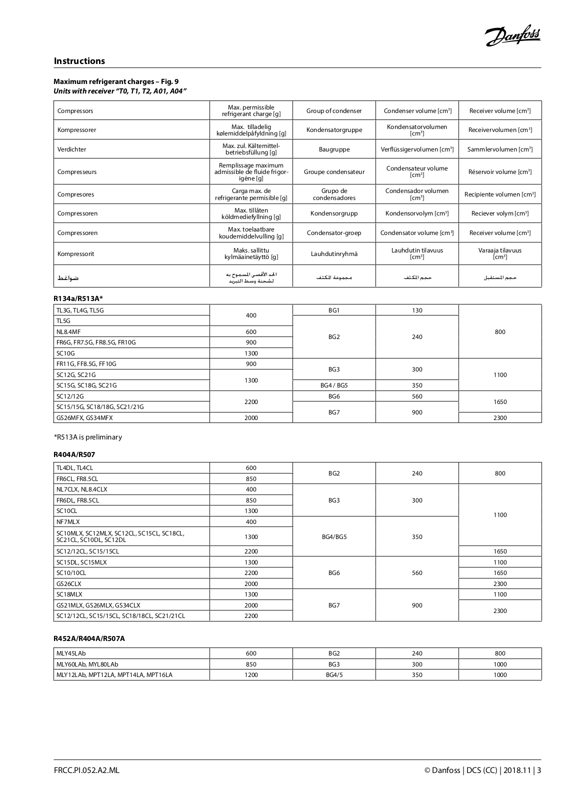
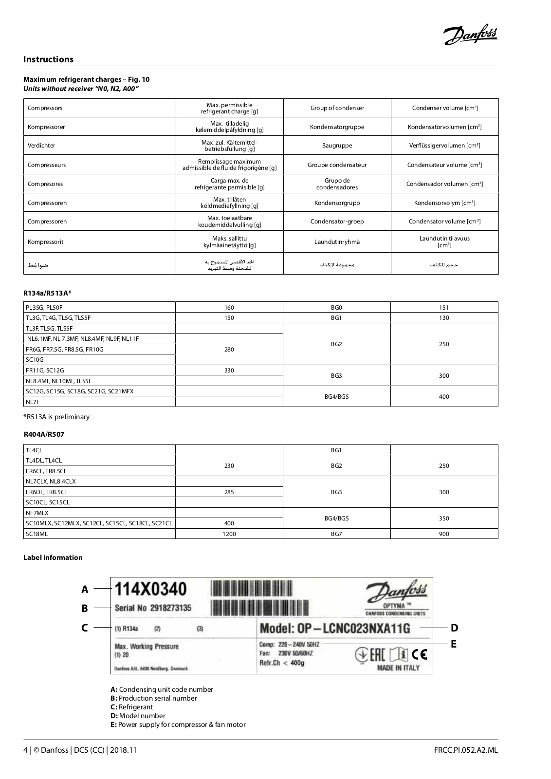
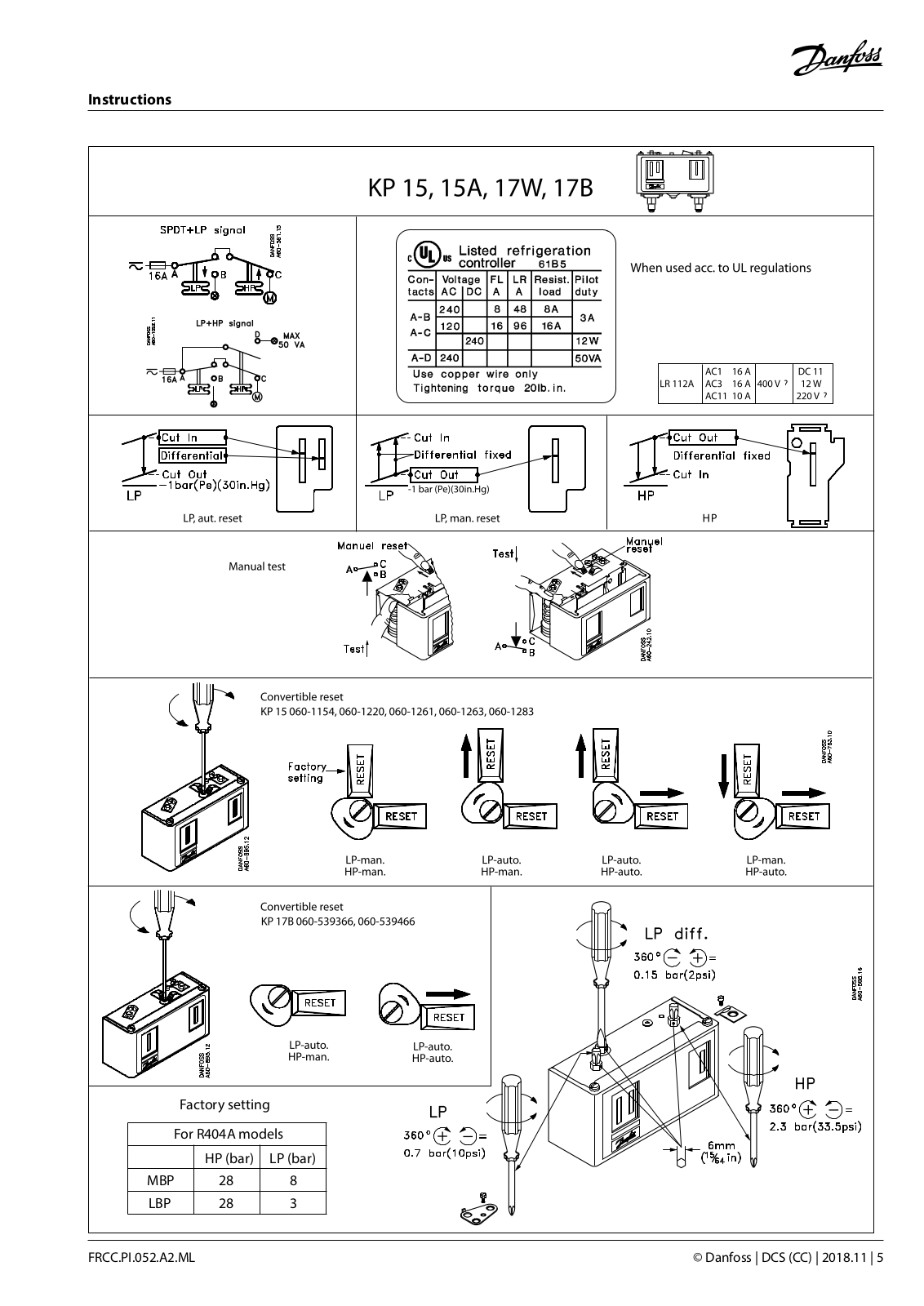
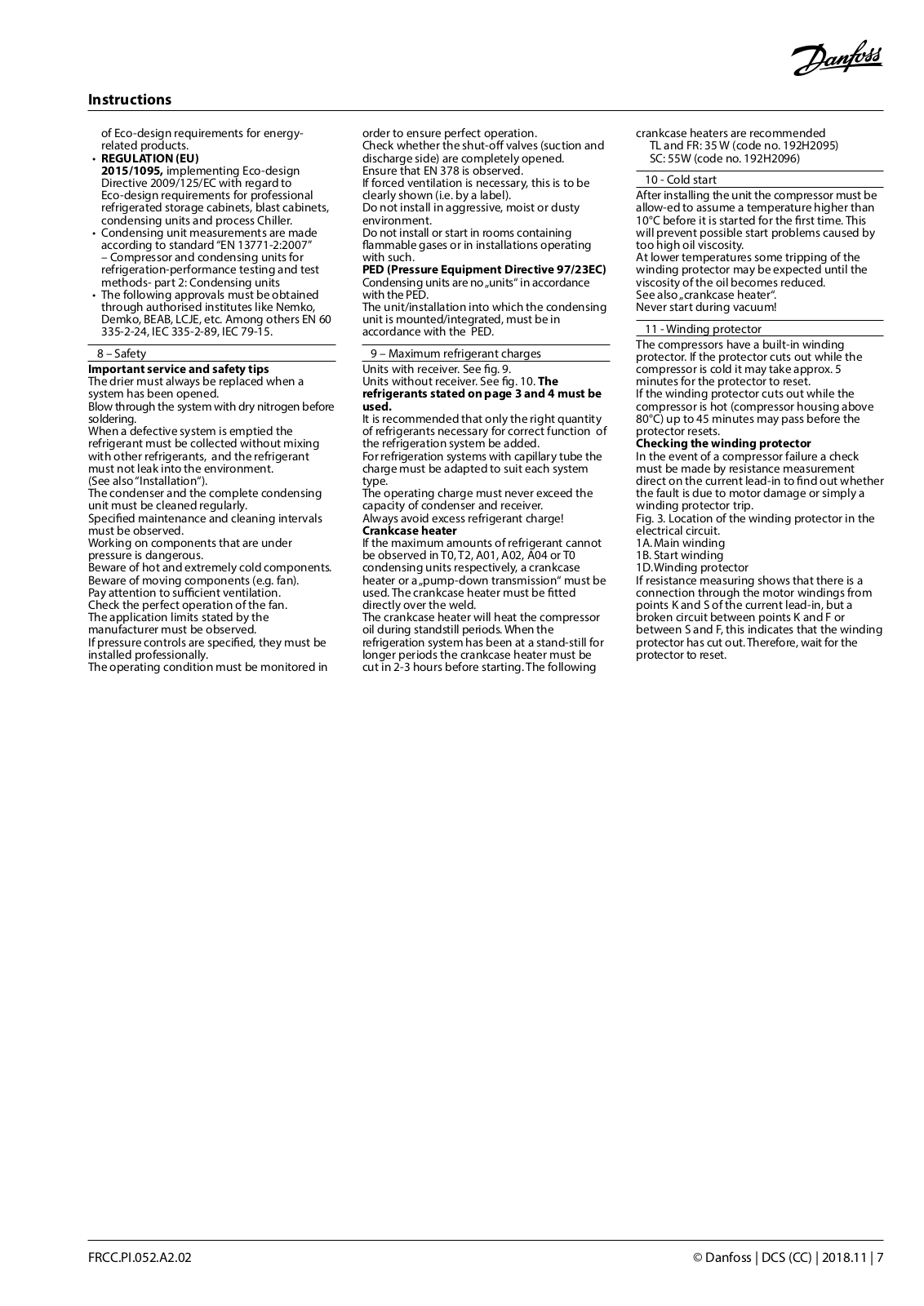
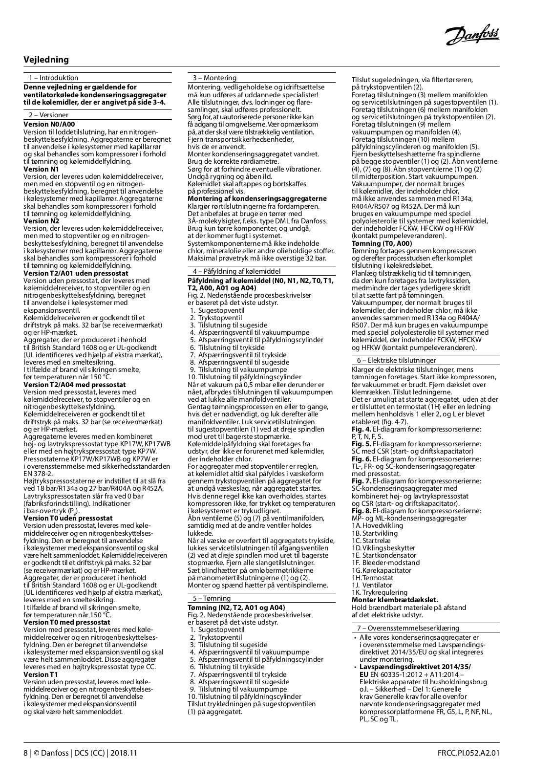
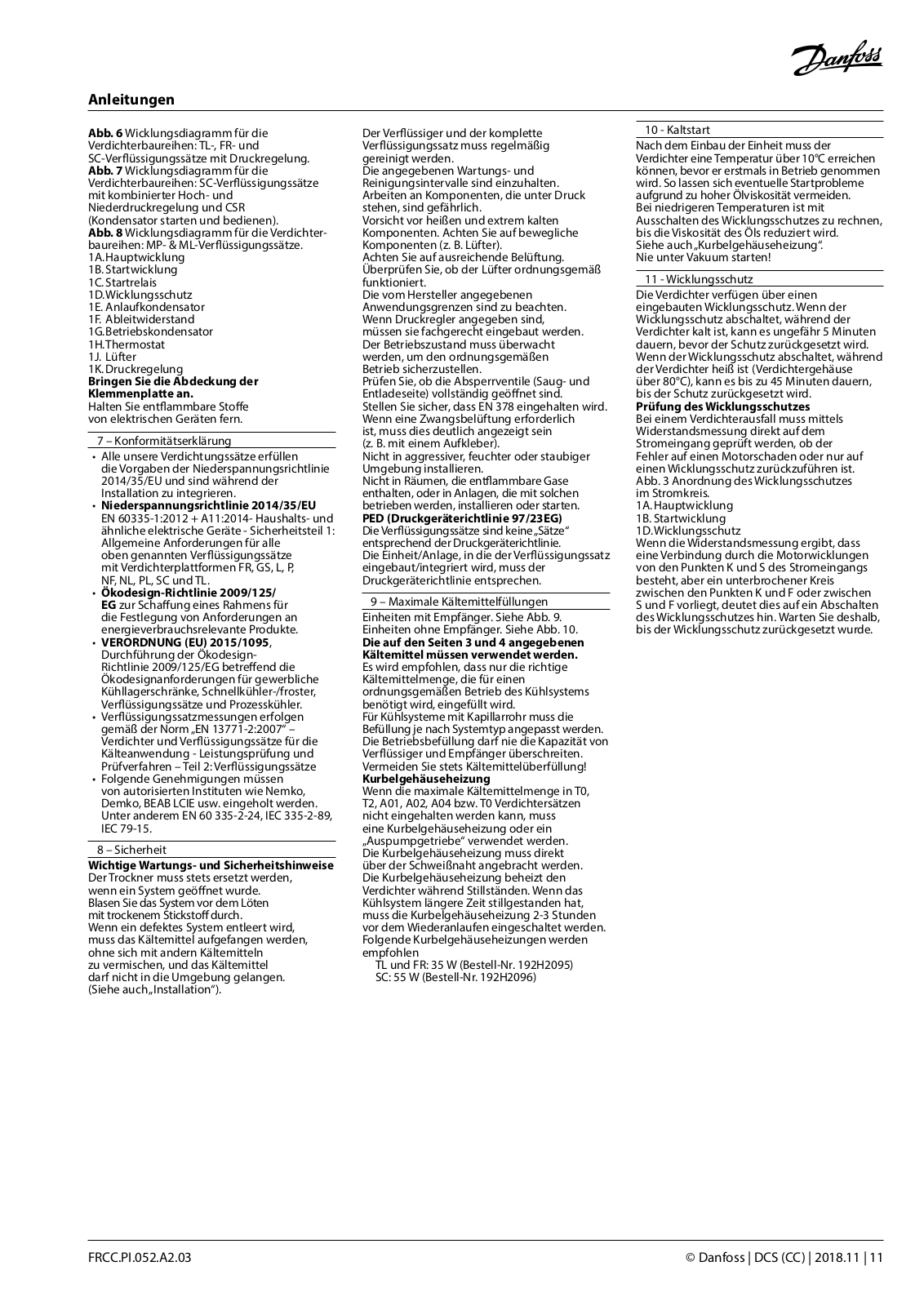
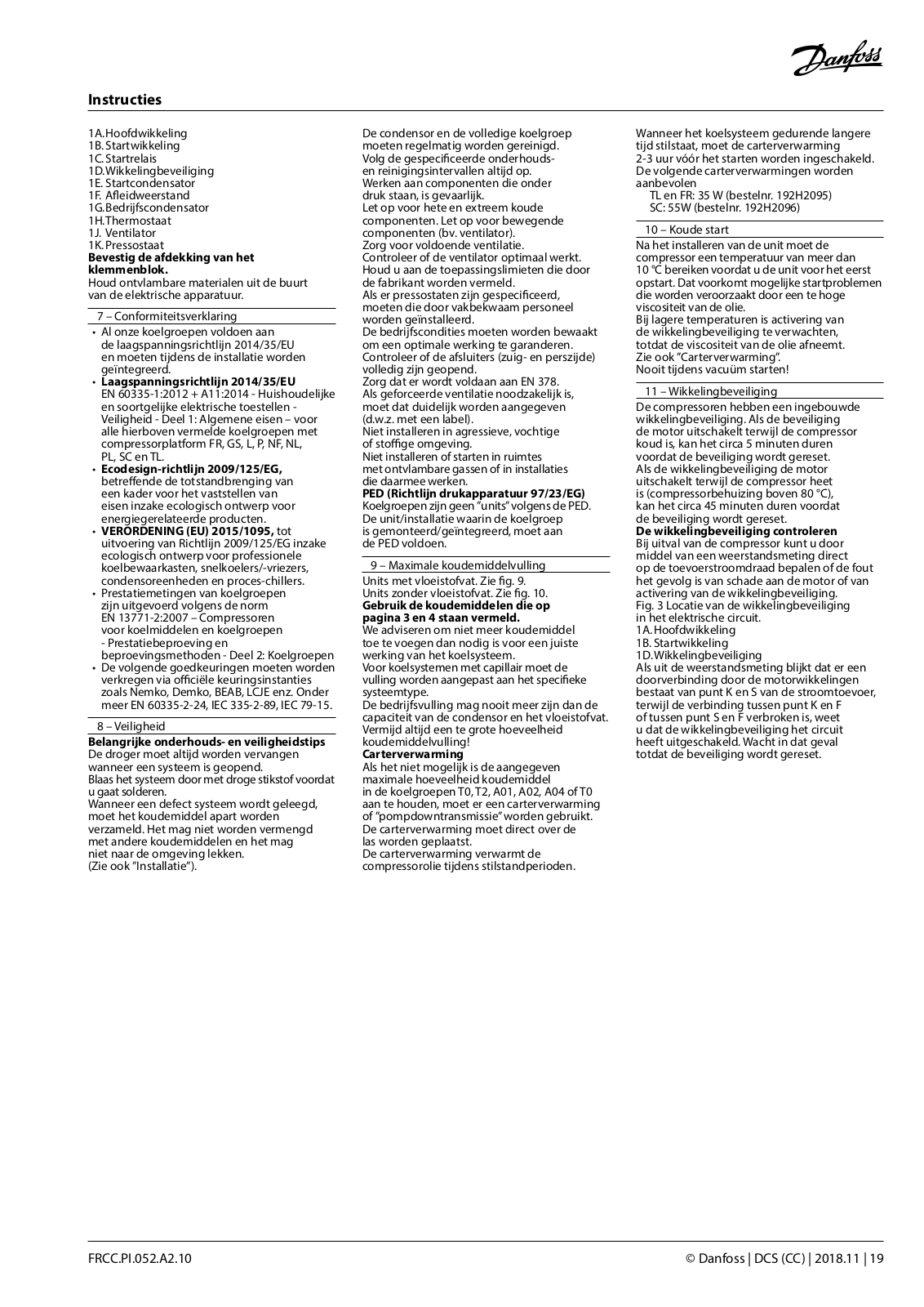
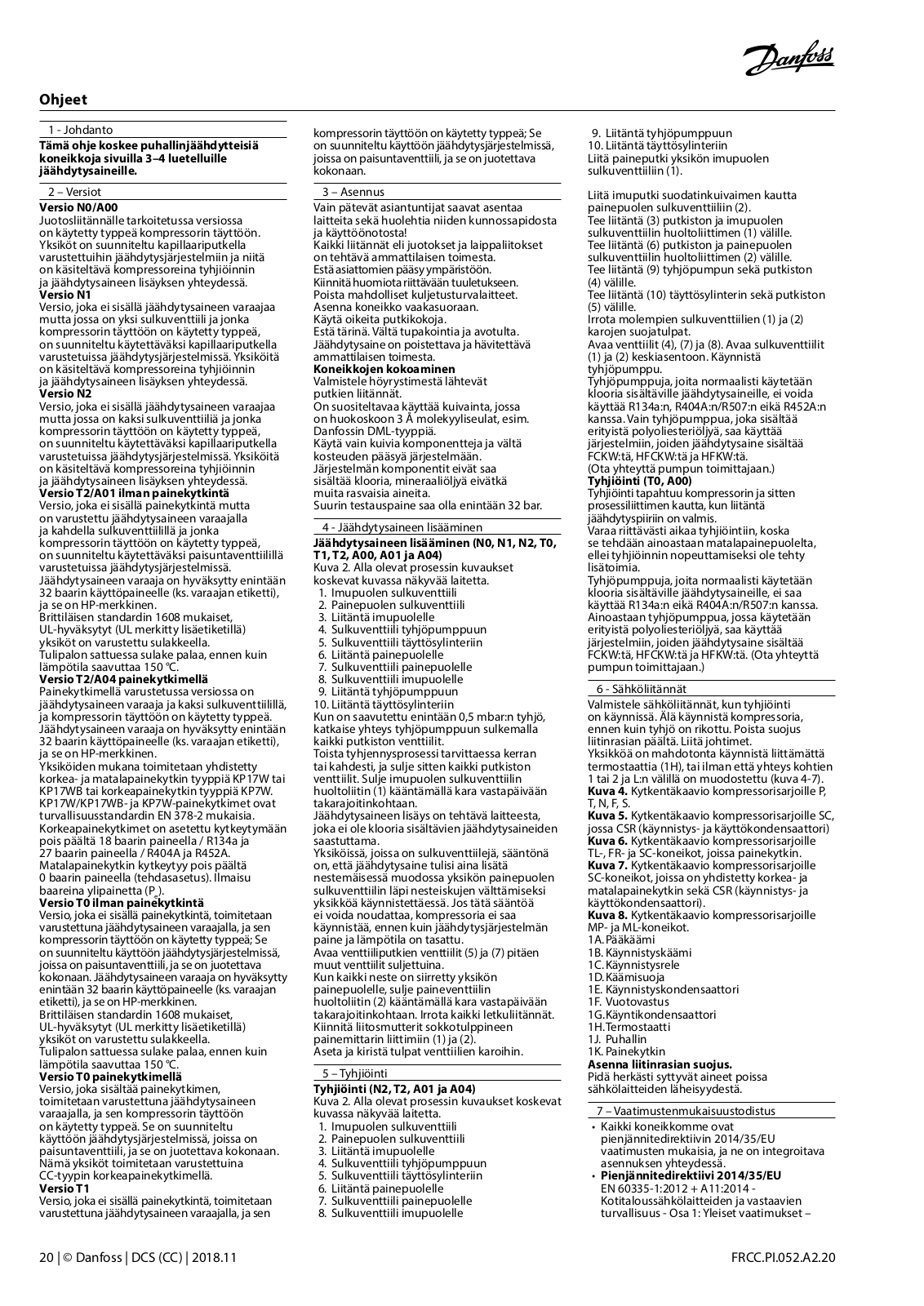
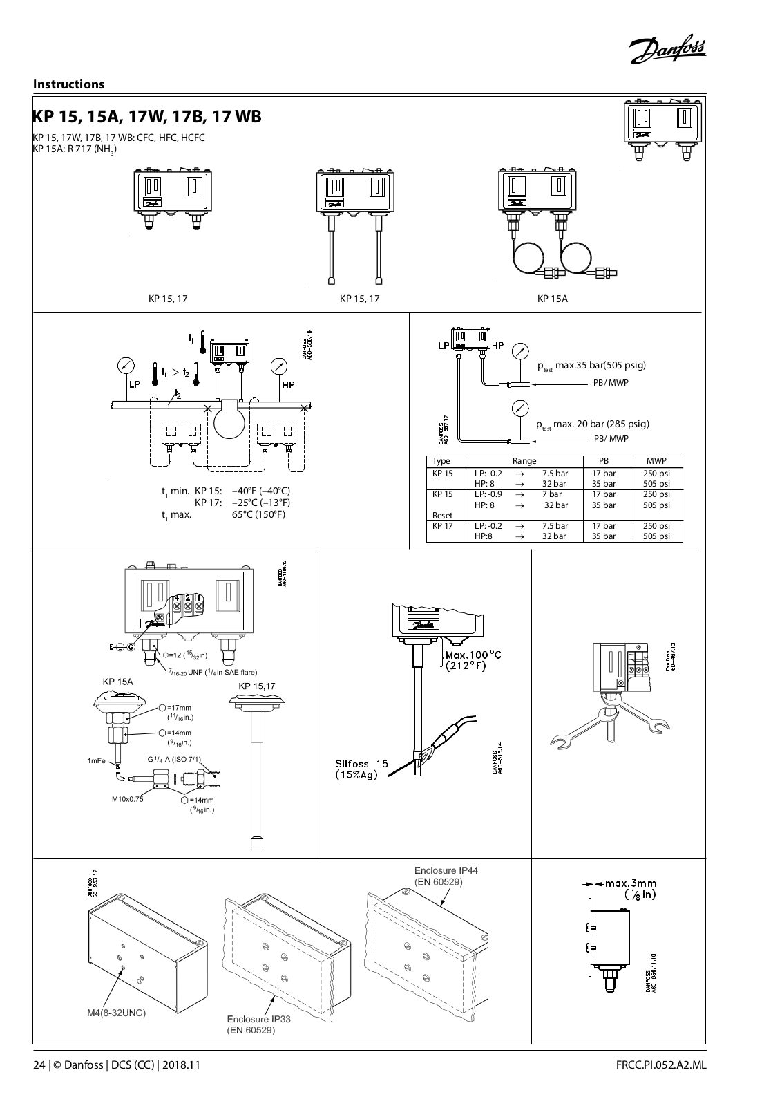
Fan-cooled non packaged condensing units
Installation guide [da]
26 pgs
1.27 Mb
0
Table of contents
Loading...
Danfoss Fan-cooled non packaged condensing units Installation guide [da]
...
Danfoss Installation guide [da]
Download
Specifications and Main Features
Frequently Asked Questions
User Manual
Download
Page 1
Page 2
Page 3
Page 4
Page 5
Page 6
Page 7
Page 8
Page 9
Page 10
Page 11
Page 12
Page 13
Page 14
Page 15
Page 16
Page 17
Page 18
Page 19
Page 20
Page 21
Page 22
Page 23
Page 24
Page 25
Page 26
Loading...
+
hidden pages
Unhide
You need points to download manuals.
1 point = 1 manual.
You can buy points or you can get point for every manual you upload.
Buy points
Upload your manuals