

Page 1
Installation Instructions
Fan Assembly
1.1.1 Items Supplied
Fan assembly
•
1.1.2 Safety Instructions
For important information about safety precautions for instal-
®
lation, refer to VLT
Instructions
DriveMotor FCP 106 and FCM 106 Operating
WARNING
DISCHARGE TIME
The frequency converter contains DC-link capacitors, which
can remain charged even when the frequency converter is
not powered. Failure to wait the specified time after power
has been removed before performing service or repair work,
could result in death or serious injury.
1. Stop motor.
2. Disconnect AC mains, permanent magnet type
motors, and remote DC-link power supplies,
including battery back-ups, UPS, and DC-link
connections to other frequency converters.
3. Wait for the capacitors to discharge fully, before
performing any service or repair work. The duration
of waiting time is specified in Table 1.1.
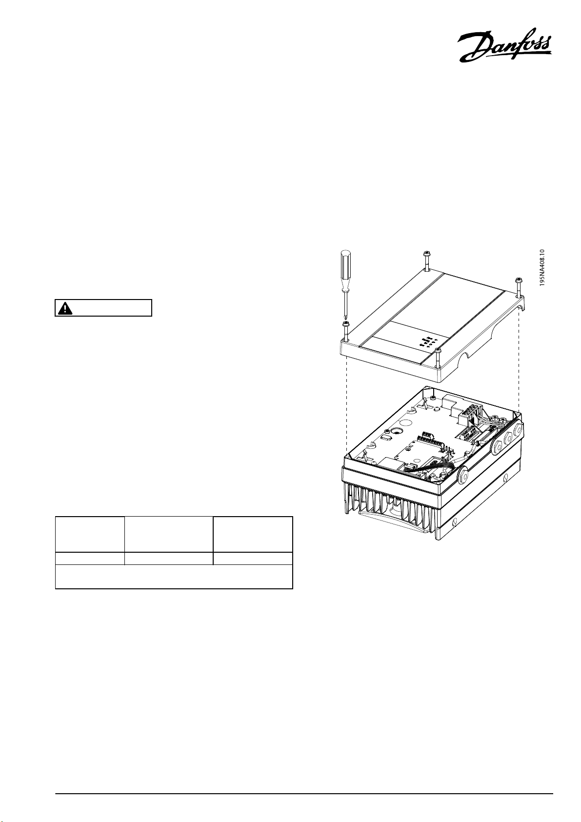
1.1.3 Remove Defect Fan Assembly
Remove the cover of the frequency converter, as shown in
Illustration 1.1.
Voltage
[V]
3x400 0.55–7.5 4
High voltage can be present even when the warning LED indicator
Table 1.1 Discharge Time
1) Power ratings relate to NO, see VLT
Operating Instructions.
Power Range
lights are off.
1)
[kW]
®
DriveMotor FCP 106 and FCM 106
Minimum waiting
time
(min)
Danfoss A/S © Rev. 2013-12-02 All rights reserved. MI03N102
Illustration 1.1 Remove Front Cover
Page 2
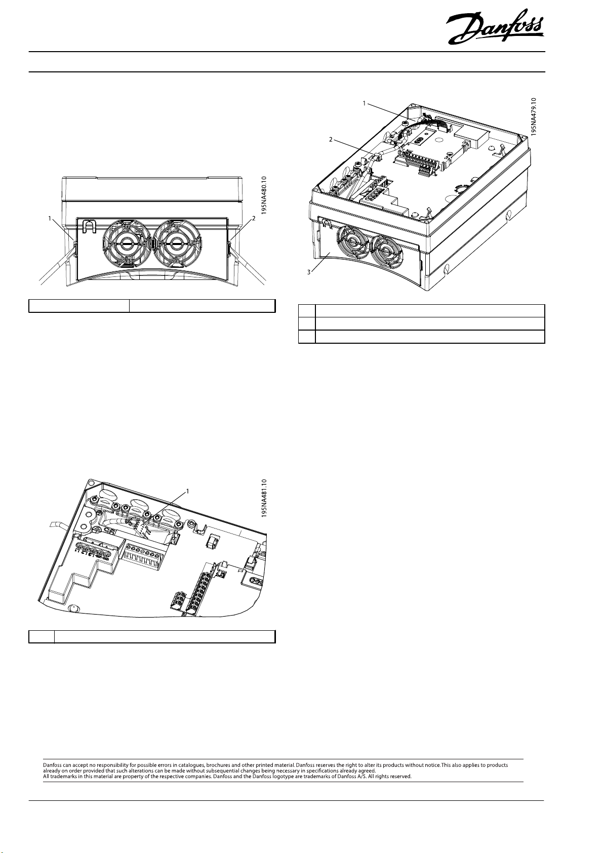
1. Unplug fan cable plug connection, see Illustration 1.4.
2. Release the fan cable.
3. Release the snaps on each side of the fan assembly,
using a screwdriver. See Illustration 1.2.
4. Lift out the fan assembly.
1, 2 Snaps
Illustration 1.2 Release the Fan Assembly
1.1.4 Install New Fan Assembly
1. Insert the fan cable through the cable entry point,
see Illustration 1.3.
2. Insert the fan assembly. Press carefully in place until
the snaps make a click sound.
3. Plug in the fan cable as shown in Illustration 1.4. Use
the cable snaps to hold the cable in place.
1 Fan cable plug connection point
2Cable snap
3 Fan assembly
Illustration 1.4 Plug in the Fan Cable
1.1.5 Replace Cover
1. When procedure is complete, reassemble frequency
converter cover in the reverse order.
2. Fasten the 4 screws using a Torx 20 screwdriver,
tightening torque 3-3.5 Nm.
1 Fan cable with plug
Illustration 1.3 Fan Cable Entry Point
MI03N102130R0559 Rev. 2013-12-02
*MI03N102*
 Loading...