

Programming Guide
VLT® AutomationDrive EZ FC 321
vlt-drives.danfoss.com


VLT® AutomationDrive EZ FC 321
Programming Guide
Contents
1
Introduction 9
1.1
Purpose of this Programming Guide 9
Supported Software Versions 9
1.2
Approvals and Certifications 9
1.3
1.4
Wiring Schematic 10
1.4.1
Start/Stop 12
1.4.2
Pulse Start/Stop 12
1.4.3
Speed Up/Speed Down 13
1.4.4
Potentiometer Reference 14
Safety Instructions 15
2
Overview 15
2.1
Target Group and Necessary Qualifications 15
2.2
Contents
Safety Symbols 15
2.3
2.4
General Safety Precautions 16
2.5
Lifting the Drive 17
2.6
Mechanical Installation Precautions 18
2.7
Safe Operation 18
3
How to Program 19
3.1
Local Control Panel 19
3.1.1
LCD Display 20
3.1.1.1
3.1.2
Quick Transfer of Parameter Settings between Multiple Drives 22
3.1.2.1
3.1.2.2
3.1.3
Display Mode 22
3.1.4
Display Mode - Selection of Readouts 22
3.1.4.1
3.1.4.2
LCP Keys 20
Transferring Data from the Drive to the LCP 22
Transferring Data from the LCP to the Drive 22
Status View I 25
Status View II 25
3.1.4.3
3.1.5
Parameter Set-up 25
3.1.6
Quick Menu Key Functions 26
3.1.7
Initial Commissioning 26
3.1.8
Main Menu Mode 29
3.1.9
Parameter Selection 29
3.1.10
Changing Data 29
Status View III 25
AU373327181955en-000101/130R1208 | 3Danfoss A/S © 2021.08

VLT® AutomationDrive EZ FC 321
Programming Guide
3.1.11
Changing a Text Value 29
3.1.12
Changing a Data Value 29
3.1.13
Infinitely Variable Change of Numeric Data Value 30
3.1.14
Value, Step by Step 30
3.1.15
Readout and Programming of Indexed Parameters 30
4
Parameter Descriptions 31
4.1
Parameter Group 0-** Operation and Display 31
4.1.1
0-0* Basic Settings 31
4.1.2
0-1* Set-up Operations 33
4.1.3
0-2* LCP Display 37
4.1.4
0-3* LCP Custom Readout 44
4.1.5
0-4* LCP Keypad 48
4.1.6
0-5* Copy/Save 50
4.1.7
0-6* Password 51
Contents
4.1.8
0-7* Clock Settings 53
4.2
Parameter Group 1-** Load and Motor 56
4.2.1
1-0* General Settings 56
4.2.2
Motor Set-ups 61
4.2.2.1
4.2.2.2
4.2.2.2.1
4.2.2.2.2
4.2.2.2.3
4.2.2.3
4.2.2.3.1
4.2.2.3.2
4.2.2.3.3
4.2.3
1-1* Special Settings 64
4.2.4
1-2* Motor Data 66
4.2.5
1-3* Adv. Motor Data 70
Asynchronous Motor Set-up 61
PM Motor Set-up 62
Rotor Detection 62
Parking 62
Application-specific Adjustment when Running VVC+ 62
SynRM Motor Set-up with VVC+ 63
Initial Programming 63
Programming Motor Data 63
Application-specific Adjustments 64
4.2.6
1-5* Load Indep. Setting 76
4.2.7
1-6* Load Depend. Setting 80
4.2.8
1-7* Start Adjustments 83
4.2.9
1-8* Stop Adjustments 86
4.2.10
1-9* Motor Temperature 89
4.2.10.1
4.2.10.2
PTC Thermistor Connection 92
KTY Sensor Connection 94
AU373327181955en-000101/130R12084 | Danfoss A/S © 2021.08

VLT® AutomationDrive EZ FC 321
Programming Guide
4.2.10.3
4.2.10.4
4.2.11
PM Settings 95
4.3
Parameter Group 2-** Brakes 96
4.3.1
2-0* DC Brakes 96
4.3.2
2-1* Brake Energy Funct. 98
4.3.3
2-2* Mechanical Brake 102
4.3.3.1
4.3.4
2-3* Adv. Mech Brake 106
4.4
Parameter Group 3-** Reference/Ramps 107
4.4.1
3-0* Reference Limits 107
4.4.2
3-1* References 109
4.4.3
3-4* Ramp 1 111
4.4.4
3-5* Ramp 2 114
Contents
ETR 94
Klixon 95
Hoist Mechanical Brake 105
4.4.5
3-6* Ramp 3 115
4.4.6
3-7* Ramp 4 117
4.4.7
3-8* Other Ramps 119
4.4.8
3-9* Digital Pot.Meter 121
4.5
Parameter Group 4-** Limits/Warnings 123
4.5.1
4-1* Motor Limits 123
4.5.2
4-2* Limit Factors 125
4.5.3
4-3* Motor Feedback Monitoring 128
4.5.4
4-4* Speed Monitor 131
4.5.5
4-5* Adjustable Warnings 133
4.5.6
4-6* Speed Bypass 137
4.5.7
4-8* Power Limit 138
4.5.8
4-9* Directional Limits 139
4.6
Parameter Group 5-** Digital I/O Mode 141
4.6.1
5-0* Digital I/O Mode 141
4.6.2
5-1* Digital Inputs 142
4.6.3
5-3* Digital Outputs 157
4.6.4
5-4* Relays 164
4.6.5
5-5* Pulse Input 170
4.6.6
5-6* Pulse Outputs 172
4.6.7
5-7* 24 V Encoder Input 175
4.6.8
5-8* I/O Options 177
4.6.9
5-9* Bus-controlled 177
4.7
Parameter Group 6-** Analog In/Out 179
AU373327181955en-000101/130R1208 | 5Danfoss A/S © 2021.08

VLT® AutomationDrive EZ FC 321
Programming Guide
4.7.1
6-0* Analog I/O Mode 179
4.7.2
6-1* Analog Input 1 180
4.7.3
6-2* Analog Input 2 182
4.7.4
6-5* Analog Output 1 184
4.8
Parameter Group 7-** Controllers 188
4.8.1
Speed PID Droop 188
4.8.2
Speed Trim 189
4.8.3
7-0* Speed PID Ctrl. 190
4.8.4
7-1* Torque PI Control 194
4.8.5
7-2* Process Ctrl. Feedb. 196
4.8.6
7-3* Process PID Ctrl. 197
4.8.7
7-4* Advanced Process PID Ctrl. 199
4.8.8
7-5* Ext. Process PID Ctrl. 201
4.9
Parameter Group 8-** Communications and Options 203
Contents
4.9.1
8-0* General Settings 203
4.9.2
8-1* Ctrl. Word Settings 206
4.9.3
8-3* FC Port Settings 213
4.9.4
8-4* FC MC Protocol Set 215
4.9.5
8-5* Digital/Bus 224
4.9.6
8-8* FC Port Diagnostics 227
4.10
Parameter Group 9-** PROFIBUS 228
4.11
Parameter Group 10-** CAN Fieldbus 228
4.12
Parameter Group 12-** Ethernet 228
4.13
Parameter Group 13-** Smart Logic Control 228
4.13.1
13-0* SLC Settings 229
4.13.2
13-1* Comparators 235
4.13.2.1
4.13.3
13-2* Timers 246
4.13.4
13-4* Logic Rules 246
4.13.5
13-5* States 256
RS FlipFlops 240
4.13.6
13-9* User-defined Alerts and Readouts 261
4.14
Parameter Group 14-** Special Functions 264
4.14.1
14-0* Inverter Switching 264
4.14.2
14-1* Mains On/Off 266
4.14.3
14-2* Trip Reset 270
4.14.4
14-3* Current Limit Control 273
4.14.5
14-4* Energy Optimizing 275
4.14.6
14-5* Environment 277
AU373327181955en-000101/130R12086 | Danfoss A/S © 2021.08

VLT® AutomationDrive EZ FC 321
Programming Guide
4.14.7
14-6* Auto Derate 280
4.14.8
14-8* Options 282
4.14.9
14-9* Fault Settings 282
4.15
Parameter Group 15-** Drive Information 284
4.15.1
15-0* Operating Data 284
4.15.2
15-1* Data Log Settings 285
4.15.3
Service Log 290
4.15.4
Clearing the Service Log 291
4.15.5
Service Log Indication 291
4.15.6
Reading the Service Log Information 291
4.15.7
Alarms that Trigger a Service Log Record 293
4.15.8
15-2* Historic Log 293
4.15.9
15-3* Alarm Log 294
4.15.10
15-4* Drive Identification 295
Contents
4.15.11
15-6* Option Ident. 298
4.15.12
15-8* Operating Data II 300
4.15.13
15-9* Parameter Info 301
4.16
Parameter Group 16-** Data Readouts 301
4.16.1
16-0* General Status 301
4.16.2
16-1* Motor Status 303
4.16.3
16-3* Drive Status 306
4.16.4
16-5* Ref. & Feedb. 309
4.16.5
16-6* Inputs and Outputs 310
4.16.6
16-8* Fieldbus & FC Port 314
4.16.7
16-9* Diagnosis Readouts 315
4.17
Parameter Group 18-** Data Readouts 2 318
4.17.1
18-0* Maintenance Log 318
4.17.2
18-3* Analog Readouts 319
4.17.3
18-5* Active Alarms/Warnings 320
4.17.4
18-6* Inputs & Outputs 2 321
4.17.5
18-7* Rectifier Status 321
4.17.6
18-9* PID Readouts 322
4.18
Parameter Group 22-** Appl. Functions 322
4.18.1
22-0* Miscellaneous 322
4.19
Parameter Group 23-** Time-based Functions 323
4.19.1
23-0* Timed Actions 323
4.19.2
23-1* Maintenance 329
4.20
Parameter Group 30-** Special Features 334
AU373327181955en-000101/130R1208 | 7Danfoss A/S © 2021.08

VLT® AutomationDrive EZ FC 321
Programming Guide
4.20.1
30-0* Wobble Function 334
4.20.2
30-2* Adv. Start Adjust 337
4.20.3
30-5* Unit Configuration 339
4.20.4
30-8* Compatibility (I) 340
4.21
Parameter Group 31-** Bypass Option 341
4.22
Parameter Group 40-** Special Settings 342
4.22.1
40-2* PM Motor Specific 342
4.22.2
40-4* Extend. Fault Log 343
4.22.3
40-5* Advanced Control Settings 344
4.23
Parameter Group 43-** Unit Readouts 345
4.23.1
43-0* Component Status 345
4.23.2
43-1* Power Card Status 346
4.23.3
43-2* Fan Pow.Card Status 347
5
Troubleshooting 349
Contents
5.1
Status Messages 349
5.1.1
Warnings and Alarms 349
5.1.2
Alarm/Warning Code List 349
5.1.3
Indicator Light 353
5.1.4
Alarm Word, Warning Word, and Extended Status Word 353
5.2
Descriptions of Warnings and Alarms 355
6
Appendix 371
6.1
Symbols and Abbreviations 371
6.2
Conventions 372
AU373327181955en-000101/130R12088 | Danfoss A/S © 2021.08
VLT® AutomationDrive EZ FC 321
Programming Guide
Introduction
1 Introduction
1.1 Purpose of this Programming Guide
This Programming Guide provides information on how to program the drive. The guide also contains full parameter descriptions.
1.2 Supported Software Versions
Supported software versions: 8.43
The software version number can be read from parameter 15-43 Software Version.
1.3 Approvals and Certifications
Table 1: Approvals and Certifications
More approvals and certifications are available. For more information, contact a local partner.
AU373327181955en-000101 / 130R1208 | 9Danfoss A/S © 2021.08
3 Phase
power
input
DC bus
Switch Mode
Power Supply
Motor
Analog Output
Interface
relay 1
relay 2
ON=Terminated
OFF=Open
Brake
resistor
e30bj070.10
91 (L1)
92 (L2)
93 (L3)
PE
88 (-)
89 (+)
50 (+10 V OUT)
53 (A IN)
54 (A IN)
55 (COM A IN)
0/4-20 mA
12 (+24 V OUT)
13 (+24 V OUT)
37 (D IN)
18 (D IN)
20
(COM D IN)
10 V DC
15 mA 130/200 mA
+ - + -
(U) 96
(V) 97
(W) 98
(PE) 99
(COM A OUT) 39
(A OUT) 42
(P RS485) 68
(N RS485) 69
(COM RS485) 61
0V
5V
S801
0/4-20 mA
RS485
RS485
03
+10 V DC
0/-10 V DC -
+10 V DC
+10 V DC
0/4-20 mA
0/-10 V DC -
240 V AC, 2 A
24 V DC
02
01
05
04
06
240 V AC, 2 A
24 V (PNP)
0 V (NPN)
0 V (NPN)
24 V (PNP)
19 (D IN)
24 V (PNP)
0 V (NPN)
27
24 V
0 V
(D IN/OUT)
0 V (NPN)
24 V (PNP)
(D IN/OUT)
0 V
24 V
29
24 V (PNP)
0 V (NPN)
0 V (NPN)
24 V (PNP)
33 (D IN)
32 (D IN)
1 2
ON
S201
ON
21
S202
ON=0/4-20 mA
OFF=0/-10 V DC +10 V DC
95
400 V AC, 2 A
Par. 5-00
21
ON
S801
(R+) 82
(R-) 81
: Chassis
: Earth
1)
1)
VLT® AutomationDrive EZ FC 321
Programming Guide
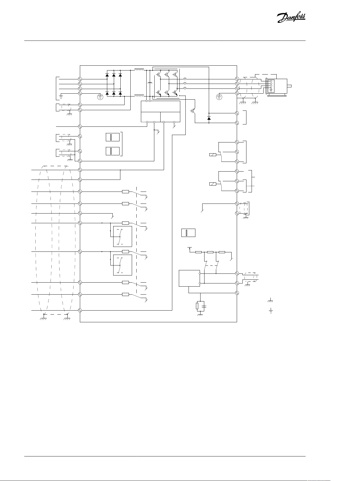
1.4 Wiring Schematic
Introduction
Illustration 1: Wiring Schematic
A=Analog, D=Digital
1) Do not connect cable shield.
Terminal 37 is used for Safe Torque Off (STO). For STO installation instructions, refer to the VLT® Frequency Converters - Safe Torque
Off Operating Guide.
Long control cables and analog signals may in rare cases, depending on installation, result in 50/60 Hz ground loops due to noise
from mains supply cables. If 50/60 Hz ground loops occur, consider breaking the shield or insert a 100 nF capacitor between shield
and enclosure.
To avoid ground currents from both groups to affect other groups, connect the digital and analog inputs and outputs separately to
the common inputs (terminals 20, 55, and 39) of the drive. For example, switching on the digital input may disturb the analog input
signal.
AU373327181955en-000101 / 130R120810 | Danfoss A/S © 2021.08
12 13 18 19 27 29 32 33 20 37
+24 VDC
0 VDC
e30bt106.10
PNP (Source)
Digital input wiring
NPN (Sink)
Digital input wiring
12 13 18 19 27 29 32 33 20 37
+24 VDC
0 VDC
e30bt107.11
VLT® AutomationDrive EZ FC 321
Programming Guide
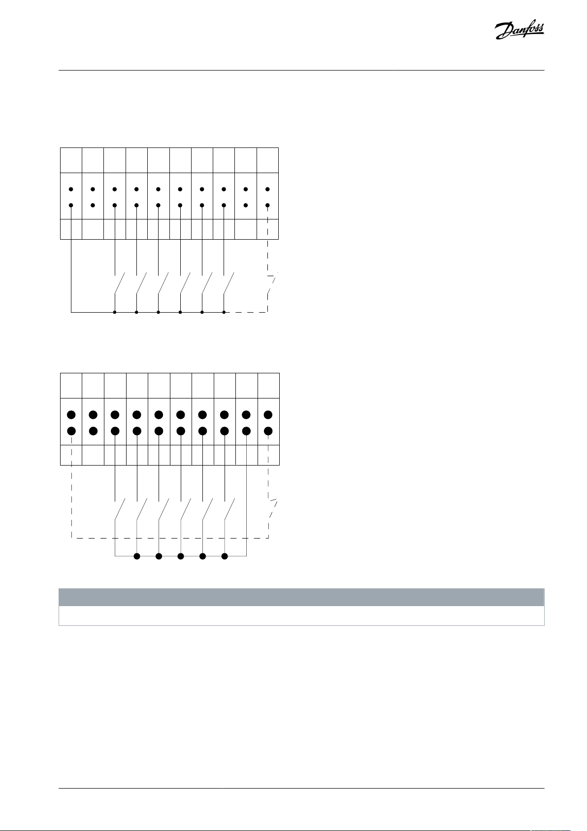
Input polarity of control terminals
Illustration 2: PNP (Source)
Introduction
Illustration 3: NPN (Sink)
Control cables must be shielded/armored.
N O T I C E
AU373327181955en-000101 / 130R1208 | 11Danfoss A/S © 2021.08
e30ba681.10
12 13 18 37
e30ba155.12
322719 29 33 20
P 5-12 [0]
P 5-10 [8]
Start/Stop
+24V
Speed
Safe Stop
Start/Stop
[18]
VLT® AutomationDrive EZ FC 321
Programming Guide
Introduction
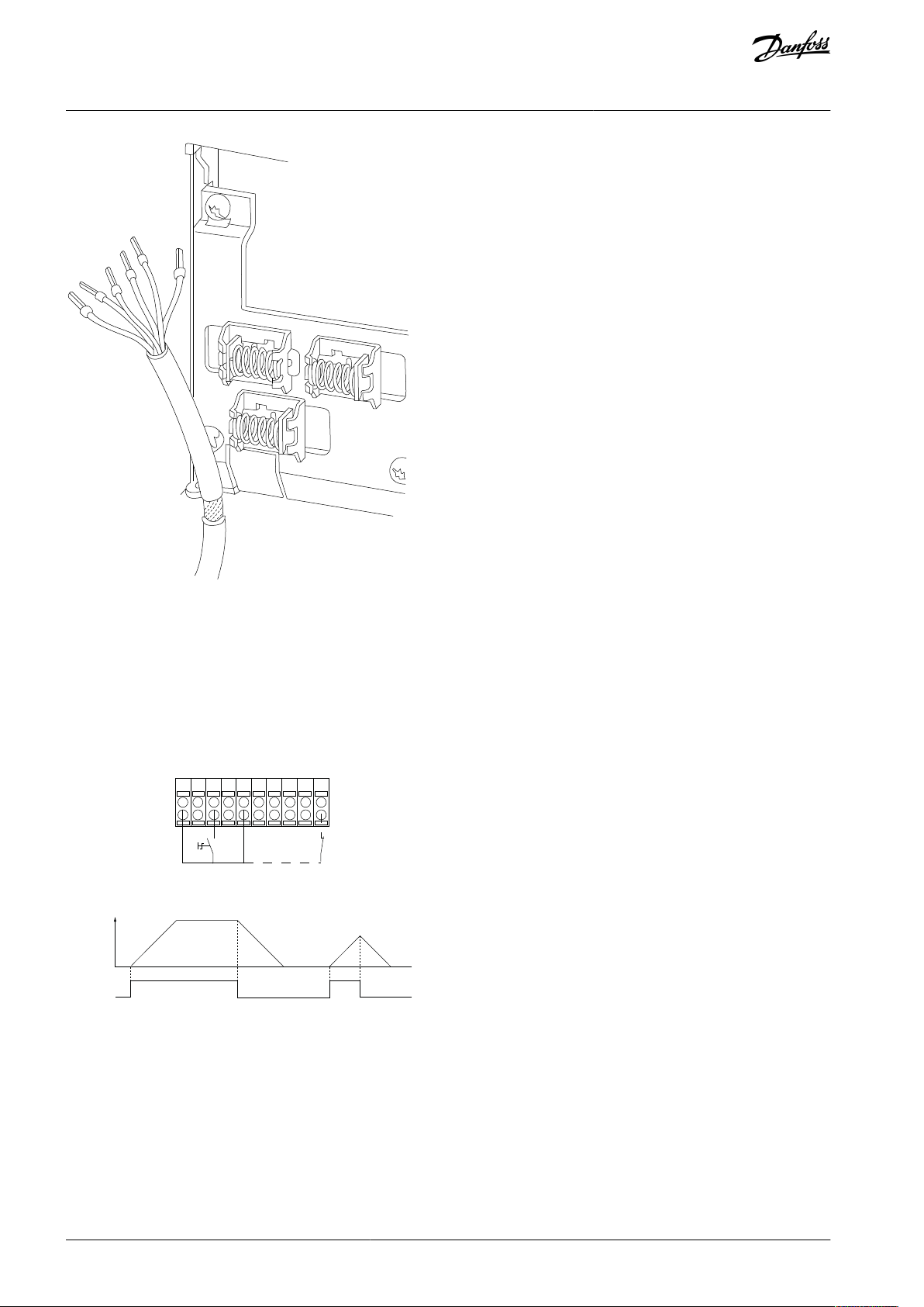
Illustration 4: Grounding of Shielded/Armored Control Cables
1.4.1 Start/Stop
Terminal 18 = Parameter 5-10 Terminal 18 Digital Input [8] Start.
Terminal 27 = Parameter 5-12 Terminal 27 Digital Input [0] No operation (Default [2] Coast inverse).
Terminal 37 = Safe Torque Off.
Illustration 5: Start/Stop
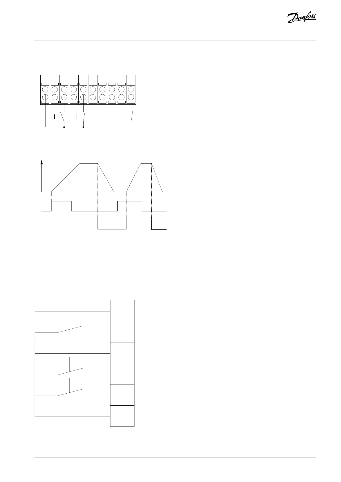
1.4.2 Pulse Start/Stop
Terminal 18 = Parameter 5-10 Terminal 18 Digital Input [9] Latched start.
Terminal 27 = Parameter 5-12 Terminal 27 Digital Input [6] Stop inverse.
Terminal 37 = Safe Torque Off.
AU373327181955en-000101 / 130R120812 | Danfoss A/S © 2021.08
12
13
18 37
e30ba156.12
32
2719
29 33 20
P 5 - 12 [6]
P 5 - 10[9]
+24V
Speed
Start
Stop inverse Safe Stop
Start (18)
Start (27)
12
18
27
29
32
37
+24V
Par. 5-10
Par. 5-12
Par. 5-13
Par. 5-14
e30ba021.13
VLT® AutomationDrive EZ FC 321
Programming Guide
Introduction
Illustration 6: Pulse Start/Stop
1.4.3 Speed Up/Speed Down
Terminal 18 = Parameter 5-10 Terminal 18 Digital Input [8] Start.
Terminal 27 = Parameter 5-12 Terminal 27 Digital Input [19] Freeze reference.
Terminal 37 = Safe Torque Off.
Terminal 29 = Parameter 5-13 Terminal 29 Digital Input [21] Speed up.
Terminal 32 = Parameter 5-14 Terminal 32 Digital Input [22] Speed down.
Illustration 7: Speed Up/Speed Down
AU373327181955en-000101 / 130R1208 | 13Danfoss A/S © 2021.08
e30ba154.11
55 50
39 42 53 54
Speed RP M
P 6-15
1 k
+10V/30mA
R
ef . v oltage
P 6-11 10V
VLT® AutomationDrive EZ FC 321
Programming Guide
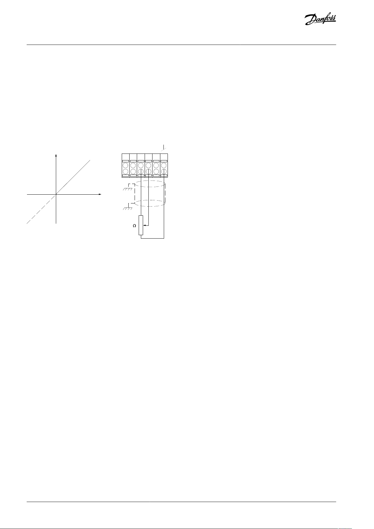
1.4.4 Potentiometer Reference
Voltage reference via a potentiometer
Reference source 1 = [1] Analog input 53 (default).
Terminal 53, low voltage = 0 V.
Terminal 53, high voltage = 10 V.
Terminal 53, low reference/feedback = 0 RPM.
Terminal 53, high reference/feedback = 1500 RPM.
Switch S201 = OFF (U)
Introduction
Illustration 8: Potentiometer Reference
AU373327181955en-000101 / 130R120814 | Danfoss A/S © 2021.08

VLT® AutomationDrive EZ FC 321
Programming Guide
Safety Instructions
2 Safety Instructions
2.1 Overview
This Safety chapter only relates to programming the drive. When installing or operating the drive, refer to the Installation Guide
applicable safety instructions. To programming this product safely:
•
Never program damaged units.
•
Follow the instructions provided in this Programming Guide.
•
Make sure that all personnel working on or with the drive have read and understood this guide and any additional product
manuals. Contact if you are unclear of the given information, or if you lack information.
2.2 Target Group and Necessary Qualifications
Correct and reliable transport, storage, installation, operation, and maintenance are required for the trouble-free and safe operation
of the drive. Only skilled personnel are allowed to perform all related activities for these tasks. Skilled personnel are defined as
properly trained staff, who are familiar with and authorized to install, commission, and maintain equipment, systems, and circuits in
accordance with pertinent laws and regulations. Also, the skilled personnel must be familiar with the instructions and safety measures described in this manual and the other product-specific manuals. If you are not a skilled electrician, do not perform any electrical installation and troubleshooting activities.
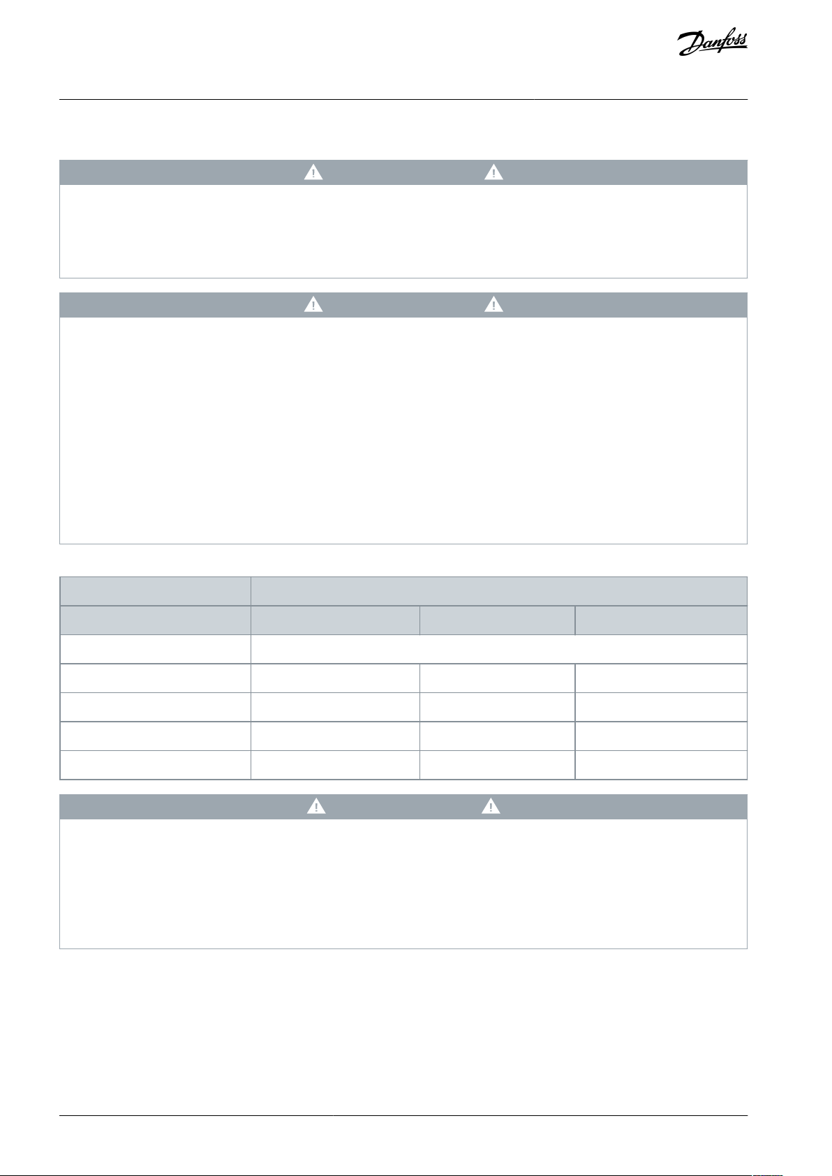
2.3 Safety Symbols
The following symbols are used in this manual:
D A N G E R
Indicates a hazardous situation which, if not avoided, will result in death or serious injury.
W A R N I N G
Indicates a hazardous situation which, if not avoided, could result in death or serious injury.
C A U T I O N
Indicates a hazardous situation which, if not avoided, could result in minor or moderate injury.
N O T I C E
Indicates information considered important, but not hazard-related (for example, messages relating to property damage).
AU373327181955en-000101 / 130R1208 | 15Danfoss A/S © 2021.08
Voltage [V]
Minimum waiting time (minutes)
41520
[hp]
200–240
0.34–5.0
7.5–50
60–100
380–500
1.0–10
15–100
125–200
525–600
1.0–10
15–100
–
525–690
––125–200
VLT® AutomationDrive EZ FC 321
Programming Guide
Safety Instructions
2.4 General Safety Precautions
W A R N I N G
HAZARDOUS VOLTAGE
AC drives contain hazardous voltage when connected to the AC mains or connected on the DC terminals. Failure to perform
installation, start-up, and maintenance by skilled personnel can result in death or serious injury.
Only skilled personnel must perform installation, start-up, and maintenance.
-
W A R N I N G
DISCHARGE TIME
The drive contains DC-link capacitors, which can remain charged even when the drive is not powered. High voltage can be
present even when the warning indicator lights are off.
Failure to wait the specified time after power has been removed before performing service or repair work can result in death or
serious injury.
Stop the motor.
-
Disconnect AC mains, permanent magnet type motors, and remote DC-link supplies, including battery back-ups, UPS, and
-
DC-link connections to other drives.
Wait for the time specified in the Discharge Time tables for the capacitors to discharge fully before performing any service or
-
repair work.
Measure the voltage level to verify full discharge.
-
Table 2: Discharge Time
C A U T I O N
HOT SURFACES
The drive contains metal components that are still hot even after the drive has been powered off. Failure to observe the high
temperature symbol (yellow triangle) on the drive can result in serious burns.
Be aware that internal components, such as busbars, may be extremely hot even after the drive has been powered off.
-
Do not touch exterior areas that are marked by the high temperature symbol (yellow triangle). These areas are hot while the
-
drive is in use and immediately after being powered off.
AU373327181955en-000101 / 130R120816 | Danfoss A/S © 2021.08

Enclosure size
Protection rating
Dimensions (HxWxD) [in]
Weight [lb]
A2
IP20/Chassis
10.6x3.6x8.7
10.8A3IP20/Chassis
10.6x5.2x8.7
14.6
A5
IP66 - Type 4X
16.6x9.6x7.9
31.5
B1
IP66 - Type 4X
18.9x9.6x10.3
51
B2
IP66 - Type 4X
25.6x9.6x10x3
60
B3
IP20/Chassis
15.8x6.5x9.8
26.5B4IP20/Chassis
20.5x9.1x9.6
52C1IP66 - Type 4X
26.8x12.2x12.3
99C2IP66 - Type 4X
30.4x14.6x13.2
143C3IP20/Chassis
21.7x12.2x13
77C4IP20/Chassis
26x14.6x13
110
D1h
Type 12
35.5x12.8x14.9
136.7
D2h
Type 12
43.6x12.8x14.9
275.6
D3h
IP20/Chassis
35.8x19.8x14.8
136.7
D4h
IP20/Chassis
44.2x14.8x14.8
238.1
VLT® AutomationDrive EZ FC 321
Programming Guide
Safety Instructions
2.5 Lifting the Drive
N O T I C E
LIFTING HEAVY LOAD
The weight of the drive is heavy and failure to follow local safety regulations for lifting heavy weights may cause death, personal
injury, or property damage.
Ensure that the lifting equipment is in proper working condition.
-
Check the weight of the drive and verify that the lifting equipment can safely lift the weight.
-
Always lift the drive using a lifting bar inserted into the lifting eyes. Maximum diameter for the lifting bar: 20 mm (0.8 in).
-
The angle from the top of the drive to the lifting cable: 60° or greater.
-
Test lift the unit approximately 610 mm (24 in) to verify the proper center of gravity lift point. Reposition the lifting point if
-
the unit is not level.
Table 3: Drive Weights and Dimensions
AU373327181955en-000101 / 130R1208 | 17Danfoss A/S © 2021.08

VLT® AutomationDrive EZ FC 321
Programming Guide
Safety Instructions
2.6 Mechanical Installation Precautions
W A R N I N G
EXPLOSIVE ATMOSPHERE
Installing the drive in a potentially explosive atmosphere can lead to death, personal injury, or property damage.
Install the unit in a cabinet outside of the potentially explosive area.
-
Use a motor with an appropriate ATEX protection class.
-
Install a PTC temperature sensor on an ATEX PTC-Thermistor device to monitor the motor temperature.
-
Install short motor cables.
-
Use sine-wave output filters when shielded motor cables are not used.
-
2.7 Safe Operation
When operating the unit, refer to the Programming Guide and Application Guide for guidance and all applicable safety instructions.
•
The drive is not suitable as the only safety device in the system. Make sure that additional monitoring and protection devices on
drives, motors, and accessories are installed according to the regional safety guidelines and accident prevention regulations.
•
Keep all doors, covers, and terminal boxes closed and securely fastened during operation.
AU373327181955en-000101 / 130R120818 | Danfoss A/S © 2021.08
Auto
On
Reset
Hand
On
Off
Status
Quick
Menu
Main
Menu
Alarm
Log
Back
Cancel
Info
OK
Status
1(0)
1234rpm
10,4A 43,5Hz
Run OK
43,5Hz
On
Alarm
Warn.
e30ba018.14
1
2
3
4
b
a
c
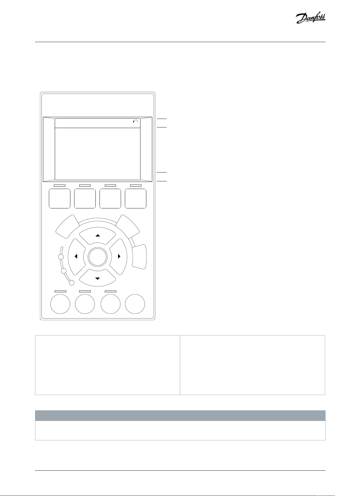
1
Graphical display with status lines.
2
Menu keys and indicator lights - changing parameters and switching between display function.
3
Navigation keys and indicator lights.
4
Operation keys and indicator lights.
a
Status line: Status messages showing icons and
graphics.
b
Line 1–2: Operator data lines showing data defined
or selected. Add up to 1 extra line by pressing [Status].cStatus line: Status messages showing text.
VLT® AutomationDrive EZ FC 321
Programming Guide
3 How to Program
3.1 Local Control Panel
Easily program the drive via the local control panel (LCP).
How to Program
Illustration 9: LCP
The LCP display can show up to 5 items of operating data while showing Status.
N O T I C E
If start-up is delayed, the LCP shows the INITIALIZING message until it is ready. Adding or removing options can delay the startup.
AU373327181955en-000101 / 130R1208 | 19Danfoss A/S © 2021.08

Top section
Middle section
Bottom section
S ta tus
43 RP M
1,4 H z
Auto Remote Running
! Pwr.card temp (W29)
2,9%
5,44 A 25,3kW
1(1)
e30bp074.10
!
e30bp044.11
On
Warn.
Alarm
LCP keys
Description
[Status]
Indicates the status of the drive and/or the motor.
Select between 3 different readouts by pressing [Status]: 5 line readouts, 4 line readouts, or smart logic control.
VLT® AutomationDrive EZ FC 321
Programming Guide
How to Program
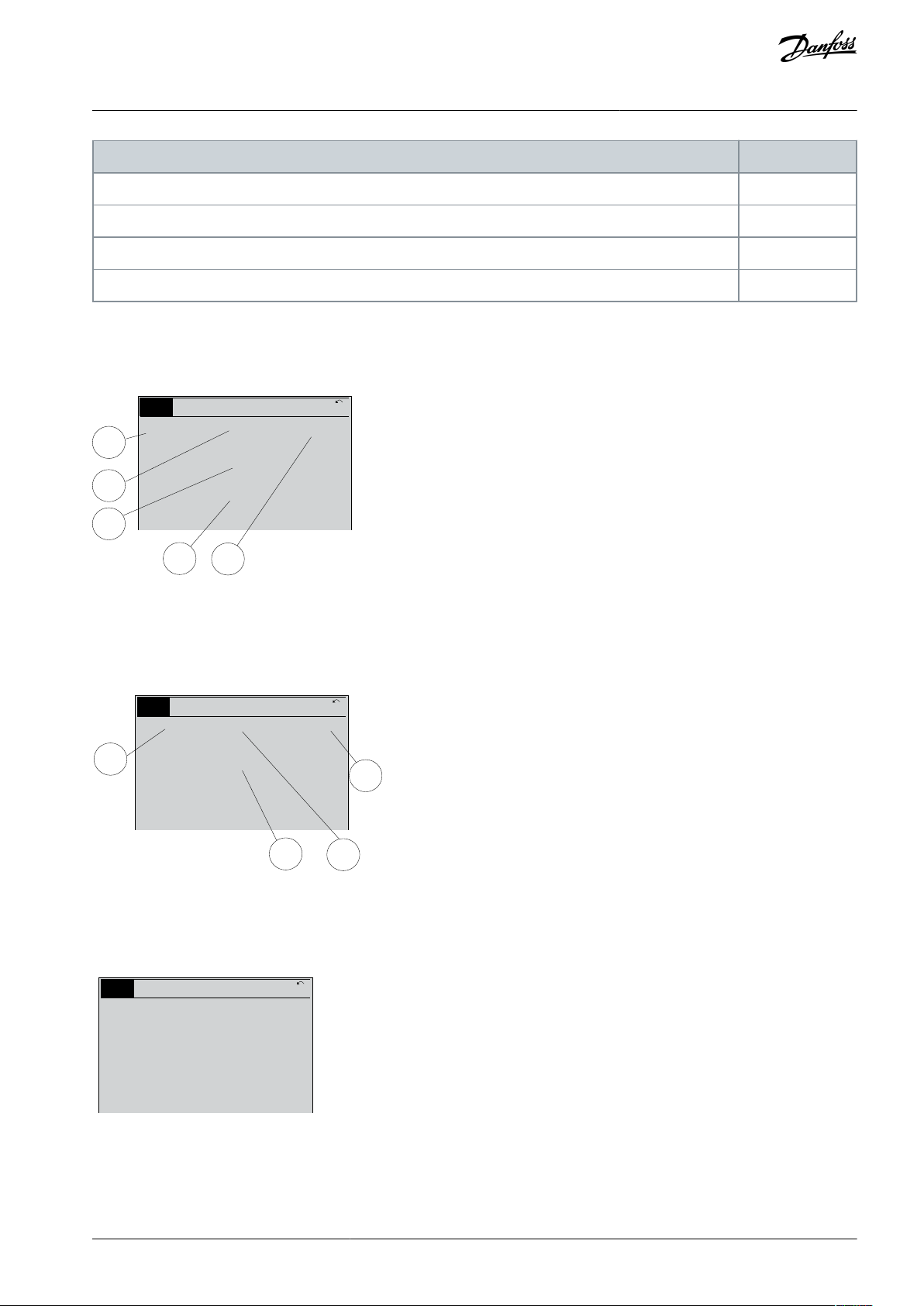
3.1.1 LCD Display
The display has backlight and a total of 6 alpha-numeric lines. The display lines show the direction of rotation (arrow), the selected
set-up, and the programming set-up. The display is divided into 3 sections.
Top section
The top section shows up to 2 measurements in normal operating status.
Middle section
The top line shows up to 5 measurements with related unit, regardless of status (except in the case of alarm/ warning).
Bottom section
The bottom section always shows the state of the drive in Status mode.
Illustration 10: Display
The active set-up (selected as the active set-up in parameter 0-10 Active Set-up) is shown. When programming another set-up than
the active set-up, the number of the programmed set-up appears to the right.
Display contrast adjustment
Press [Status] and [▵] for darker display.
Press [Status] and [▿] for brighter display.
Most parameter set-ups can be changed immediately via the LCP, unless a password has been created via parameter 0-60 Main
Menu Password or via parameter 0-65 Quick Menu Password.
Indicator lights
If certain threshold values are exceeded, the alarm and/or warning indicator lights up. A status and alarm text appear on the LCP.
The ON indicator light is activated when the drive receives mains voltage or via a DC bus terminal or 24 V external supply. At the
same time, the back indicator light is on.
Green LED/On: Control section is working.
•
Yellow LED/Warn: Indicates a warning.
•
Flashing Red LED/Alarm: Indicates an alarm.
•
Illustration 11: Indicator Lights
3.1.1.1 LCP Keys
The control keys are divided into functions. The keys below the display and indicator lights are used for parameter setup, including
option of display indication during normal operation.
Table 4: LCP Keys and Description
AU373327181955en-000101 / 130R120820 | Danfoss A/S © 2021.08

•
•
•
•
•
•
•
•
•
•
•
•
LCP keys
Description
Press [Status] for selecting the mode of display or for changing back to display mode from either the quick menu
mode, the main menu mode, or the alarm mode. Also use [Status] to toggle single or double readout mode.
[Quick
Menu]
Allows quick access to different quick menus such as:
My personal menu
Quick set-up
Changes made
Loggings
Press [Quick Menu] to program the parameters belonging to the Quick Menu. It is possible to switch directly between quick menu mode and main menu mode.
[Main
Menu]
Is used for programming all parameters. It is possible to switch directly between main menu mode and quick menu
mode. Parameter shortcut can be carried out by pressing down [Main Menu] for 3 s. The parameter shortcut allows
direct access to any parameter.
[Alarm
Log]
Shows an alarm list of the 5 latest alarms (numbered A1– A5). To obtain extra details about an alarm, press the
navigation keys to maneuver to the alarm number and press [OK]. Information about the condition of the drive
before it enters the alarm mode is shown.
[Back]
Returns to the previous step or layer in the navigation structure.
[Cancel]
Last change or command is canceled as long as the display has not been changed.
[Info]
Supplies information about a command, parameter, or function in any display window. [Info] provides detailed information whenever help is needed. Exit Info mode by pressing either [Info], [Back], or [Cancel].
Navigation keys
The 4 navigation keys are used to navigate between the different options available in Quick Menu, Main Menu, and
Alarm Log. Press the keys to move the cursor.
[OK] Press to select a parameter marked by the cursor and to enable the change of a parameter.
LCP
keys
Description
[Hand
On]
Enables control of the drive via the LCP.
[Hand On] also starts the motor, and it is now possible to enter the motor speed data with the navigation keys. The
key can be selected as [1] Enable or [0] Disable via parameter 0-40 [Hand on] Key on LCP.
External stop signals activated with control signals or a fieldbus override a start command via the LCP.
The following control signals are still active when [Hand On] is activated:
[Hand on] - [Off] - [Auto On]
Reset
Coast stop inverse
Reversing
Set-up select bit 0 - Set-up select bit 1
Stop command from serial communication
Quick stop
DC brake
[Off]
Stops the connected motor. The key can be selected as [1] Enable or [0] Disable via parameter 0-41 [Off] Key on LCP.
VLT® AutomationDrive EZ FC 321
Programming Guide
How to Program
Local control keys: Local control keys are at the bottom of the control panel.
Table 5: Local Control Keys and Description
AU373327181955en-000101 / 130R1208 | 21Danfoss A/S © 2021.08

LCP
keys
Description
If external stop function is not selected and the [Off] key is inactive, the motor can be stopped by disconnecting the
voltage.
[Auto
On]
Enables the drive to be controlled via the control terminals and/or serial communication.
When a start signal is applied on the control terminals and/or the bus, the drive starts. The key can be selected as [1]
Enable or [0] Disable via parameter 0-42 [Auto on] Key on LCP.
Note: An active HAND-OFF-AUTO signal via the digital inputs has higher priority than the control keys [Hand On] –
[Auto On].
[Reset]
Is used for resetting the drive after an alarm (trip). It can be selected as [1] Enable or [0] Disable via parameter 0-43
[Reset] Key on LCP.
The parameter shortcut can be carried out by pressing down the [Main Menu] key for 3 s. The parameter shortcut
provides direct access to any parameter.
VLT® AutomationDrive EZ FC 321
Programming Guide
How to Program
3.1.2 Quick Transfer of Parameter Settings between Multiple Drives
When the set-up of a drive is completed, store the data in the LCP. Then connect the LCP to another drive and copy the parameter
settings to the new drive.
3.1.2.1 Transferring Data from the Drive to the LCP
Procedure
1.
Go to parameter 0-50 LCP Copy.
2.
Press [OK].
3.
Select [1] All to LCP.
Press [OK].
4.
3.1.2.2 Transferring Data from the LCP to the Drive
Procedure
1.
Go to parameter 0-50 LCP Copy.
Press [OK].
2.
3.
Select [2] All from LCP.
Press [OK].
4.
3.1.3 Display Mode
In normal operation, up to 5 different operating variables can be indicated continuously in the middle section: 1.1, 1.2, and 1.3, as
well as 2 and 3.
3.1.4 Display Mode - Selection of Readouts
It is possible to toggle between 3 status readout screens by pressing [Status].
Operating variables with different formatting are shown in each status view (status view I, status view II, status view III).
The following table shows the measurements that can be linked to each of the operating variables. When options are mounted,
additional measurements are available.
Define the links via:
•
Parameter 0-20 Display Line 1.1 Small.
•
Parameter 0-21 Display Line 1.2 Small.
•
Parameter 0-22 Display Line 1.3 Small.
•
Parameter 0-23 Display Line 2 Large.
•
Parameter 0-24 Display Line 3 Large.
Each readout parameter selected in parameter 0-20 Display Line 1.1 Small to parameter 0-24 Display Line 3 Large has its own scale and
digits after a possible decimal point. The larger the numeric value of a parameter is, the fewer digits are shown after the decimal
point.
Example: Current readout 5.25 A, 15.2 A, 105 A.
AU373327181955en-000101 / 130R120822 | Danfoss A/S © 2021.08

Operating variable
Unit
Parameter 16-00 Control Word
hex
Parameter 16-01 Reference [Unit]
[Unit]
Parameter 16-02 Reference [%]
%
Parameter 16-03 Status Word
hex
Parameter 16-05 Main Actual Value [%]
%
Parameter 16-09 Custom Readout
Parameter 16-10 Power [kW]
[kW]
Parameter 16-11 Power [hp]
[hp]
Parameter 16-12 Motor Voltage
[V]
Parameter 16-13 Frequency
[Hz]
Parameter 16-14 Motor current
[A]
Parameter 16-15 Frequency [%]
Parameter 16-16 Torque [Nm]
Nm
Parameter 16-17 Speed [RPM]
[RPM]
Parameter 16-18 Motor Thermal
%
Parameter 16-20 Motor Angle
Parameter 16-21 Torque [%] High Res.
Parameter 16-22 Torque [%]
Parameter 16-24 Calibrated Stator Resistance
Parameter 16-30 DC Link Voltage
V
Parameter 16-34 Heatsink Temp.
°C
Parameter 16-35 Inverter Thermal
%
Parameter 16-36 Inv. Nom. Current
A
Parameter 16-37 Inv. Max. Current
A
Parameter 16-38 SL Controller State
Parameter 16-39 Control Card Temp.
°C
Parameter 16-40 Logging Buffer Full
Parameter 16-45 Motor Phase U Current
Parameter 16-46 Motor Phase V Current
Parameter 16-47 Motor Phase W Current
Parameter 16-48 Speed Ref. After Ramp [RPM]
Parameter 16-49 Current Fault Source
VLT® AutomationDrive EZ FC 321
Programming Guide
Table 6: Units
How to Program
AU373327181955en-000101 / 130R1208 | 23Danfoss A/S © 2021.08

Operating variable
Unit
Parameter 16-50 External Reference
Parameter 16-51 Pulse Reference
Parameter 16-52 Feedback[Unit]
[Unit]
Parameter 16-53 Digi Pot Reference
Parameter 16-57 Feedback [RPM]
Parameter 16-60 Digital Input
bin
Parameter 16-61 Terminal 53 Switch Setting
V
Parameter 16-62 Analog Input 53
Parameter 16-63 Terminal 54 Switch Setting
V
Parameter 16-64 Analog Input 54
Parameter 16-65 Analog Output 42 [mA]
[mA]
Parameter 16-66 Digital Output [bin]
[bin]
Parameter 16-67 Pulse Input #29 [Hz]
[Hz]
Parameter 16-68 Freq. Input #33 [Hz]
[Hz]
Parameter 16-69 Pulse Output #27 [Hz]
[Hz]
Parameter 16-70 Pulse Output #29 [Hz]
[Hz]
Parameter 16-71 Relay Output [bin]
Parameter 16-72 Counter A
Parameter 16-73 Counter B
Parameter 16-75 Analog In X30/11
Parameter 16-76 Analog In X30/12
Parameter 16-77 Analog Out X30/8 [mA]
Parameter 16-80 Fieldbus CTW 1
hex
Parameter 16-82 Fieldbus REF 1
hex
Parameter 16-84 Comm. Option STW
hex
Parameter 16-85 FC Port CTW 1
hex
Parameter 16-86 FC Port REF 1
hex
Parameter 16-87 Bus Readout Alarm/Warning
Parameter 16-90 Alarm Word
Parameter 16-91 Alarm Word 2
Parameter 16-92 Warning Word
Parameter 16-93 Warning Word 2
VLT® AutomationDrive EZ FC 321
Programming Guide
How to Program
AU373327181955en-000101 / 130R120824 | Danfoss A/S © 2021.08
Operating variable
Unit
Parameter 16-94 Ext. Status Word
Parameter 16-95 Ext. Status Word 2
Parameter 16-97 Alarm Word 3
Parameter 16-98 Warning Word 3
1.1
2
3
1.3
1.2
e30bp041.10
799 RPM
1 (1)
36.4 kW 7.83 A
0.000
53.2 %
S t a tus
Auto Remote Ramping
1.1
2
1.3
1.2
e30bp062.10
207 RPM
1 (1)
24.4 kW 5.25 A
6.9 Hz
S
t a
tus
Auto Remote Running
e30bp063.10
778 RPM
1 (1)
4.0 kW 0.86 A
S t a tus
Auto Remote Running
State: 0 off 0 (off)
When: Do: -
VLT® AutomationDrive EZ FC 321
Programming Guide
How to Program
3.1.4.1 Status View I
This readout state is standard after start-up or initialization. Press [Info] to obtain information about the units linked to the shown
operating variables (1.1, 1.2, 1.3, 2 and 3). See the operating variables shown in the following illustration.
Illustration 12: Status View I
3.1.4.2 Status View II
See the operating variables (1.1, 1.2, 1.3, and 2) shown in the following illustration. In the example, speed, motor current, motor
power, and frequency are selected as variables in the 1st and 2nd lines.
Illustration 13: Status View II
3.1.4.3 Status View III
This state shows the event and action of the smart logic control.
Illustration 14: Status View III
3.1.5 Parameter Set-up
The drive can be used for practically all assignments. The drive offers an option between 2 programming modes:
AU373327181955en-000101 / 130R1208 | 25Danfoss A/S © 2021.08
e30bc916.10
Q1 My Personal Menu
Q2 Quick Setup
Q4 Smart Setup
Q5 Changes Made
0RPM 0.00A 1(1)
Quick Menus
Parameter
Setting
Parameter 0-01 Language
Parameter 1-20 Motor Power [kW]
[kW]
Parameter 1-22 Motor Voltage
[V]
Parameter 1-23 Motor Frequency
[Hz]
Parameter 1-24 Motor Current
[A]
Parameter 1-25 Motor Nominal Speed
[RPM]
Parameter 3-02 Minimum Reference
[RPM]
VLT® AutomationDrive EZ FC 321
Programming Guide
•
Main menu mode
•
Quick menu mode
How to Program
Main menu provides access to all parameters.
Quick menu takes the user through a few parameters, making it possible to start operating the drive. Change a parameter in either
main menu mode or quick menu mode.
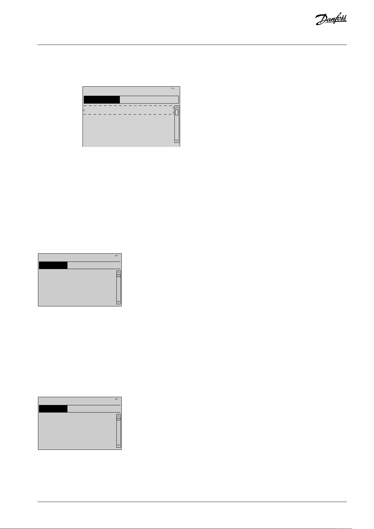
3.1.6 Quick Menu Key Functions
Press [Quick Menu] to enter a list of different areas contained in the Quick Menu.
Illustration 15: Quick Menus
Select Q1 My Personal Menu to show the selected personal parameters. These parameters are selected in parameter 0-25 My Personal
Menu. Up to 50 different parameters can be added in this menu.
Select Q2 Quick Setup to go through a selection of parameters to get the motor running almost optimally. The default settings for
the other parameters consider the required control functions and the configuration of signal inputs/outputs (control terminals).
The parameter selection is effected with the navigation keys. The parameters in the following table are accessible.
Table 7: Selection of Parameter
Select Changes made to get information about:
•
The last 10 changes. Use the [▵] [▿] navigation keys to scroll between the last 10 changed parameters.
•
The changes made since default setting.
Select Loggings to get information about the shown line readouts. The information is shown as graphs. Only parameters selected in
parameter 0-20 Display Line 1.1 Small and parameter 0-24 Display Line 3 Large can be viewed. It is possible to store up to 120 samples
in the memory for later reference.
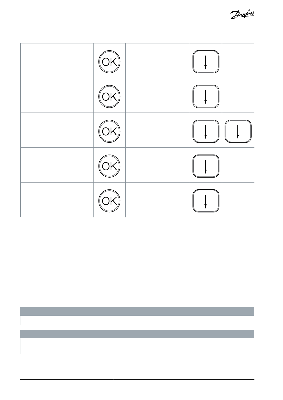
3.1.7 Initial Commissioning
The easiest way of carrying out the initial commissioning is by pressing [Quick Menu] and following the quick set-up procedure
using LCP 102 (read the following table from left to right). The example applies to open-loop applications.
AU373327181955en-000101 / 130R120826 | Danfoss A/S © 2021.08
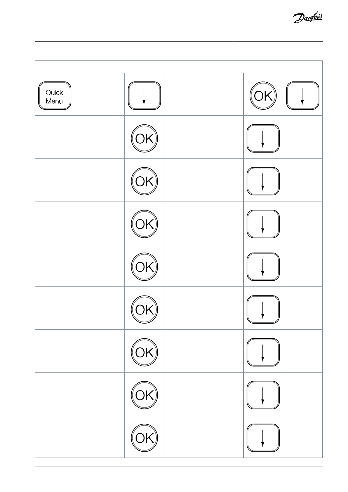
Press
Q2 Quick Menu.
Parameter 0-01 Language
Set language.
Parameter 1-20 Motor Power [kW]
Set motor nameplate power.
Parameter 1-22 Motor Voltage
Set nameplate voltage.
Parameter 1-23 Motor Frequency
Set nameplate frequency.
Parameter 1-24 Motor Current
Set nameplate current.
Parameter 1-25 Motor Nominal Speed
Set nameplate speed in RPM.
Parameter 5-12 Terminal 27 Digital Input
If terminal default is [2] Coast inverse, it is possible to change this
setting to [0] No function. No connection to terminal 27 is then
needed for running AMA.
Parameter 1-29 Automatic Motor Adaptation (AMA)
Set desired AMA function. Enable
complete AMA is recommended.
VLT® AutomationDrive EZ FC 321
Programming Guide
Table 8: Quick Set-up Procedure
How to Program
AU373327181955en-000101 / 130R1208 | 27Danfoss A/S © 2021.08
Parameter 3-02 Minimum Reference
Set the minimum speed of the
motor shaft.
Parameter 3-03 Maximum Reference
Set the maximum speed of the
motor shaft.
Parameter 3-41 Ramp 1 Ramp Up Time
Set the ramp-up time with reference to synchronous motor
speed, ns.
Parameter 3-42 Ramp 1 Ramp Down
Time
Set the ramp-down time with reference to synchronous motor
speed, ns.
Parameter 3-13 Reference Site
Set the site from where the reference must work.
VLT® AutomationDrive EZ FC 321
Programming Guide
How to Program
Another easy way of commissioning the drive is by using the smart application set-up (SAS), which can also be found by pressing
[Quick Menu]. To set up the applications listed, follow the instructions on the successive screens.
The [Info] key can be used throughout the SAS to see help information for various selections, settings, and messages. The following
3 applications are included:
•
Mechanical brake.
•
Conveyor.
•
Pump/fan.
The following 4 fieldbusses can be selected:
•
PROFIBUS.
•
PROFINET.
•
DeviceNet.
•
EtherNet/IP.
N O T I C E
The drive ignores the start conditions when SAS is active.
N O T I C E
The smart set-up runs automatically on the first power-up of the drive or after a reset to factory settings. If no action is taken, the
SAS screen automatically disappears after 10 minutes.
AU373327181955en-000101 / 130R120828 | Danfoss A/S © 2021.08
e130bp066.13
1-** Load/Motor
2-** Brakes
1107 RPM 3.84 A
M
ain M
enu
1(1)
3-** References/Ramps
0-** Operation/Display
e30bp067.10
740R P M
0 -01 Language
[0] English
10.64A 1 [1]
0-0*
Basic S ettings
e30bp067.10
740R P M
0 -01 Language
[0] English
10.64A 1 [1]
0-0*
Basic S ettings
VLT® AutomationDrive EZ FC 321
Programming Guide
How to Program
3.1.8 Main Menu Mode
Press [Main Menu] to enter the main menu mode. The readout in the following illustration appears on the display. The middle and
bottom sections in the display show a list of parameter groups, which can be selected by toggling the [▵] and [▿] keys.
Illustration 16: Main Menu Mode
Each parameter has a name and number which remain the same regardless of the programming mode. In the main menu mode,
the parameters are divided into groups. The first digit of the parameter number (from the left) indicates the parameter group number.
All parameters can be changed in the Main Menu. However, depending on the choice of configuration (parameter 1-00 Configura-
tion Mode), some parameters can be hidden. For example, open loop hides all the PID parameters, and other enabled options make
more parameter groups visible.
3.1.9 Parameter Selection
In the main menu mode, the parameters are divided into groups. Select a parameter group with the navigation keys.
After selecting a parameter group, select a parameter with the navigation keys.
The middle section on the display shows the parameter number and name, and the selected parameter value.
Illustration 17: Parameter Selection
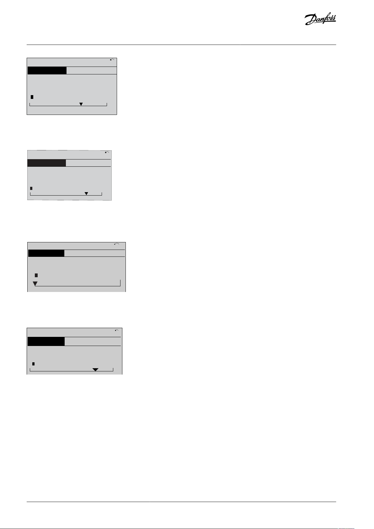
3.1.10 Changing Data
The procedure for changing data in the quick menu mode and the main menu mode is the same. Press [OK] to change the selected
parameter.
The procedure for changing data depends on whether the selected parameter represents a numeric data value or a text value.
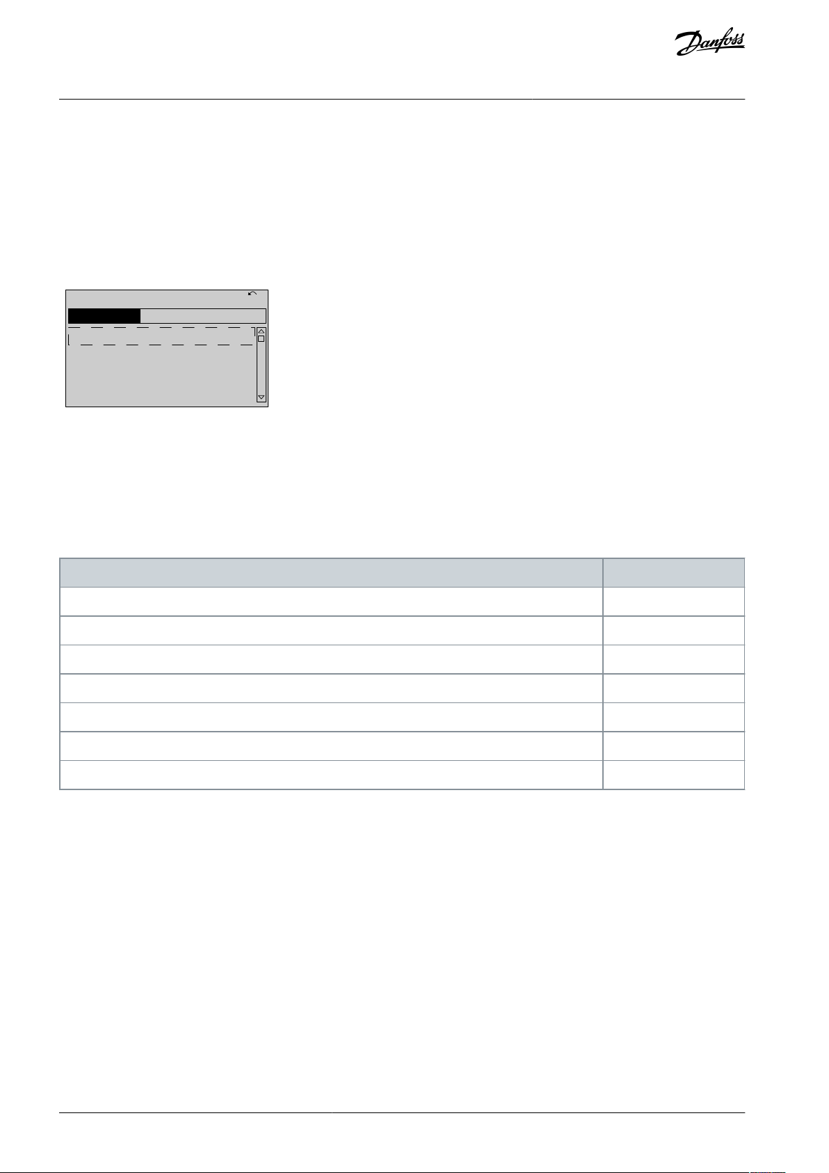
3.1.11 Changing a Text Value
If the selected parameter is a text value, change the text value with the [▵] [▿] keys.
Place the cursor on the value to save and press [OK].
Illustration 18: Changing a Text Value
3.1.12 Changing a Data Value
If the selected parameter shows a numeric data value, change the selected data value with the [◃] [▹] and the [▵] [▿] navigation keys.
Press the [◃] [▹] keys to move the cursor horizontally.
AU373327181955en-000101 / 130R1208 | 29Danfoss A/S © 2021.08
e30bp069.10
1- 6*
113 RP M 1.78 A 1(1)
L oad depen. setting
1 - 60 L
o w speed load
c
ompensa tion
1
0 0%
e30bp070.10
1 - 60 L o w speed load
c
ompensa tion
1 0%
L
oad depen. setting 1- 6*
729RP
M
6.21A 1(1)
6
e30bp073.10
635 RP M
1 - 71 S tar t D ela y
00. 0 s
0.44 A 1 (1)
1- 7*
S tar t A djustmen ts
e30bp072.10
957RP
M
1-71 H
igh star
ting t or que time
0. s
11.58A 1 (1)
1-7*
S
tar
t A
djustmen
ts
4
VLT® AutomationDrive EZ FC 321
Programming Guide
How to Program
Illustration 19: Changing a Data Value
Press the [▵] [▿] keys to change the data value. [▵] increases the data value, and [▿] decreases the data value. Place the cursor on the
value to save and press [OK].
Illustration 20: Saving a Data Value
3.1.13 Infinitely Variable Change of Numeric Data Value
If the selected parameter shows a numeric data value, select a digit with [◃] [▹].
Illustration 21: Selecting a Digit
Change the selected digit infinitely variably with [▵] [▿]. The cursor indicates the selected digit. Place the cursor on the digit to save
and press [OK].
Illustration 22: Saving
3.1.14 Value, Step by Step
Certain parameters can be changed step by step. This applies to:
•
Parameter 1-20 Motor Power [kW].
•
Parameter 1-22 Motor Voltage.
•
Parameter 1-23 Motor Frequency.
The parameters are changed both as a group of numeric data values and as numeric data values that are infinitely varying.
3.1.15 Readout and Programming of Indexed Parameters
Parameters are indexed when placed in a rolling stack. Parameter 15-30 Fault Log: Error Code to parameter 15-32 Alarm Log: Time
contain a fault log, which can be read out. Select a parameter, press [OK], and press the [▵] [▿] keys to scroll through the value log.
AU373327181955en-000101 / 130R120830 | Danfoss A/S © 2021.08

0-01 Language
Default value: [0] English
Parameter type: Option
Setup: 1 setup
Conversion index: –
Data type: Uint8
Change during operation: True
Option
Name
Description
[0]*
English
Part of languages packages 1–4.
[1]
Deutsch
Part of languages packages 1–4.
[2]
Français
Part of language package 1.
[3]
Dansk
Part of language package 1.
[4]
Español
Part of language package 1.
[5]
Italiano
Part of language package 1.
[6]
Svenska
Part of language package 1.
[7]
Nederlands
Part of language package 1.
[10]
Chinese
Part of language package 2.
[20]
Suomi
Part of language package 1.
[22]
English US
Part of language package 4.
[27]
Greek
Part of language package 4.
[28]
Bras. Port
Part of language package 4.
[36]
Slovenian
Part of language package 3.
[39]
Korean
Part of language package 2.
[40]
Japanese
Part of language package 2.
[41]
Turkish
Part of language package 4.
[42]
Trad.Chinese
Part of language package 2.
[43]
Bulgarian
Part of language package 3.
[44]
Srpski
Part of language package 3.
[45]
Romanian
Part of language package 3.
[46]
Magyar
Part of language package 3.
VLT® AutomationDrive EZ FC 321
Programming Guide
Parameter Descriptions
4 Parameter Descriptions
4.1 Parameter Group 0-** Operation and Display
Parameters related to the basic functions of the drive, the function of the LCP keys, and the configuration of the LCP display.
4.1.1 0-0* Basic Settings
Parameter 0-01 Language
Table 9: Parameter 0-01 Language
Defines the language to be used in the display. The drive is delivered with 4 different language packages. English and German are
included in all packages. English cannot be erased or manipulated.
AU373327181955en-000101 / 130R1208 | 31Danfoss A/S © 2021.08

Option
Name
Description
[47]
Czech
Part of language package 3.
[48]
Polski
Part of language package 4.
[49]
Russian
Part of language package 3.
[50]
Thai
Part of language package 2.
[51]
Bahasa Indonesia
Part of language package 2.
0-02 Motor Speed Unit
Default value: –
Parameter type: Option
Setup: 2 setups
Conversion index: –
Data type: Uint8
Change during operation: False
Option
Name
Description
[0]
RPM
Select to show motor speed variables and parameters using motor speed (RPM).
[1]HzSelect to show motor speed variables and parameters using output frequency (Hz).
0-03 Regional Settings
Default value: –
Parameter type: Option
Setup: 2 setups
Conversion index: –
Data type: Uint8
Change during operation: False
Option
Name
Description
[0]
International
Activate parameter 1-20 Motor Power [kW] for setting the motor power in kW and set the default value of
parameter 1-23 Motor Frequency to 50 Hz.
[1]
US
Activate parameter 1-20 Motor Power [kW] for setting the motor power in hp and set the default value of
parameter 1-23 Motor Frequency to 60 Hz.
VLT® AutomationDrive EZ FC 321
Programming Guide
Parameter 0-02 Motor Speed Unit
Table 10: Parameter 0-02 Motor Speed Unit
N O T I C E
This parameter cannot be adjusted while the motor is running.
Parameter Descriptions
N O T I C E
Changing the motor speed unit resets certain parameters to their initial value. Select the motor speed unit before modifying other parameters.
The information shown in the display depends on the settings in parameter 0-02 Motor Speed Unit and parameter 0-03 Regional Set-
tings. The default settings of parameter 0-02 Motor Speed Unit and parameter 0-03 Regional Settings depend on the region to which
the drive is supplied.
Parameter 0-03 Regional Settings
Table 11: Parameter 0-03 Regioanl Settings
N O T I C E
This parameter cannot be adjusted while the motor is running.
AU373327181955en-000101 / 130R120832 | Danfoss A/S © 2021.08

0-04 Operating State at Power-up (Hand)
Default value: [1] Forced stop, ref=old
Parameter type: Option
Setup: All setups
Conversion index: –
Data type: Uint8
Change during operation: True
Option
Name
Description
[0]
Resume
Restart the drive, maintaining the start/stop settings (applied by [Hand On]/[Off]) selected before
the power-down of the drive.
[1]*
Forced stop,
ref=old
Restart the drive with a saved local reference after mains voltage reappears and after pressing
[Hand On].
[2]
Forced stop, ref=0
Reset the local reference to 0 when restarting the drive.
0-10 Active Set-up
Default value: [1] Set-up 1
Parameter type: Option
Setup: 1 setup
Conversion index: –
Data type: Uint8
Change during operation: True
Option
Name
Description
[0]
Factory setup
Cannot be changed. It contains the data set and can be used as a data source when returning the other
setups to a known state.
[1]*
Set-up 1
[1] Set-up 1 to [4] Set-up 4 are the 4 separate parameter setups within which all parameters can be programmed.
[2]
Set-up 2
VLT® AutomationDrive EZ FC 321
Programming Guide
Parameter 0-04 Operating State at Power-up (Hand)
Table 12: Parameter 0-04 Operating State at Power-up (Hand)
Select the operating mode upon reconnection of the drive to mains voltage after power-down in hand-on mode.
Parameter Descriptions
4.1.2 0-1* Set-up Operations
Define and control the individual parameter setups. The drive has 4 parameter setups that can be programmed independently of
each other. This makes the drive very flexible and able to solve advanced control functionality problems, often saving the cost of
external control equipment. Parameter setups can be used to program the drive to operate according to 1 control scheme in 1
setup (for example, motor 1 for horizontal movement) and another control scheme in another setup (for example, motor 2 for vertical movement). Alternatively, parameter setups can be used by an OEM machine builder to identically program all their factoryfitted drives for different machine types within a range to have the same parameters. During production/commissioning, simply
select a specific setup depending on which machine the drive is installed on.
The active setup (that is the setup in which the drive is currently operating) can be selected in parameter 0-10 Active Set-up and is
shown in the LCP. By using multi setup, it is possible to switch between setups with the drive running, or it can be stopped via
digital input or serial communication commands. If it is necessary to change setups while the drive is running, ensure that parame-
ter 0-12 This Set-up Linked to is programmed as required. By using parameter 0-11 Edit Set-up, it is possible to edit parameters within
any of the setups while continuing the operation of the drive in its active setup, which can be a different setup to the one being
edited. By using parameter 0-51 Set-up Copy, it is possible to copy parameter settings between the set-ups to enable quicker commissioning if similar parameter settings are required in different setups.
Use parameter 0-51 Set-up Copy to copy a setup to 1 or all other setups. Stop the drive before switching between setups where
parameters marked not changeable during operation have different values. To avoid conflicting settings of the same parameter
within 2 different setups, link the setups together using parameter 0-12 This Set-up Linked to. Parameters which are not changeable
during operation are marked FALSE in the Change during operation field.
Parameter 0-10 Active Set-up
Table 13: Parameter 0-10 Active Set-up
Select the setup to control the drive functions.
AU373327181955en-000101 / 130R1208 | 33Danfoss A/S © 2021.08

Option
Name
Description
[3]
Set-up 3
[4]
Set-up 4
[9]
Multi Set-up
Remote setup selections using digital inputs and the serial communication port. This setup used the
settings from parameter -012 This Set-up Linked to. Stop the drive before making changes to open-loop
and closed-loop functions.
0-11 Edit Set-up
Default value: [1] Set-up 1
Parameter type: Option
Setup: All setups
Conversion index: –
Data type: Uint8
Change during operation: True
Option
Name
Description
[0]
Factory setup
Cannot be edited, but it is useful as a data source to return the other setups to a known state.
[1]*
Set-up 1
[1] Set-up 1 to [4] Set-up 4 can be edited freely during operation, independently of the active set-up.
[2]
Set-up 2
[3]
Set-up 3
[4]
Set-up 4
[9]
Active Set-up
Can also be edited during operation. Edit the selected setup from a range of sources: LCP, FC RS485, FC
USB, or up to 5 fieldbus sites.
VLT® AutomationDrive EZ FC 321
Programming Guide
Parameter 0-11 Edit Set-up
Table 14: Parameter 0-11 Edit Set-up
Select the setup to be edited (that is programmed) during operation, either the active setup or 1 of the inactive setups.
Parameter Descriptions
AU373327181955en-000101 / 130R120834 | Danfoss A/S © 2021.08

e30ba199.11
1
2
3
4
1
2
3
4
1
2
3
4
1
2
3
4
P 0-11
P 0-11
P 0-11
P 0-11
Set-up
Set-up
Set-up
Set-up
PLC Fieldbus
0-12 This Set-up Linked to
Default value: [0] Not linked
Parameter type: Option
Setup: All setups
Conversion index: –
Data type: Uint8
Change during operation: False
Option
Name
Description
[0]*
Not linked
[1]
Set-up 1
VLT® AutomationDrive EZ FC 321
Programming Guide
Parameter Descriptions
Illustration 23: Edit Setup
Parameter 0-12 This Set-up Linked to
Table 15: Parameter 0-12 This Set-up Linked to
To enable conflict-free changes from 1 setup to another during operation, link setups containing parameters which are not changeable during operation. The link ensures synchronizing of the not changeable during operation-parameter values when moving from
1 setup to another during operation. Not changeable during operation-parameters can be identified by the label FALSE in the
Change during operation field. Parameter 0-12 This Set-up Linked to is used by [9] Multi set-up in parameter 0-10 Active Set-up. Multi
setup is used to move from 1 setup to another during operation.
AU373327181955en-000101 / 130R1208 | 35Danfoss A/S © 2021.08

Option
Name
Description
[2]
Set-up 2
[3]
Set-up 3
[4]
Set-up 4
e75bp075.11
e30bp076.11
0-12 This Set-up Linked to
0 RPM 0.00A 1(1)
Set-up Handling 0-1*
[2] Setup 2
0-13 Readout: Linked Set-ups
Default value: 0
Parameter type: Range [0–255]
Setup: All setups
Conversion index: 0
Data type: Uint16
Change during operation: False
VLT® AutomationDrive EZ FC 321
Programming Guide
Example
Use multi set-up to shift from setup 1 to setup 2 while the motor is running. Program in setup 1 first, then ensure that setup 1 and
setup 2 are synchronized (or linked). Synchronization can be performed in 2 ways:
•
Select the following options:
-
[2] Set-up 2 in parameter 0-11 Edit Set-up
-
Set parameter 0-12 This Set-up Linked to to [1] Set-up 1.
Parameter Descriptions
Illustration 24: Set-up 1
•
While still in setup 1, copy setup 1 to setup 2. Then set parameter 0-12 This Set-up Linked to to [2] Set-up 2.
Illustration 25: Setup 2
Parameter 0-13 Readout: Linked Set-ups
Table 16: Parameter 0-13 Readout: Linked Set-ups
View a list of all the setups linked by parameter 0-12 This Set-up Linked to. The parameter has 1 index for each parameter setup. The
value for each index shows which setups are linked to that parameter setup.
AU373327181955en-000101 / 130R120836 | Danfoss A/S © 2021.08

Index
LCP value
0
{0}1{1,2}2{1,2}3{3}4{4}
0-14 Readout: Edit Set-ups/Channel
Default value: 0
Parameter type: Range [-2147483648–2147483648]
Setup: All setups
Conversion index: 0
Data type: Int32
Change during operation: True
0-15 Readout: Actual Set-up
Default value: 0
Parameter type: Range [0–255]
Setup: All setups
Conversion index: 0
Data type: Uint8
Change during operation: False
0-20 Display Line 1.1 Small
Default value: –
Parameter type: Option
Setup: All setups
Conversion index: –
Data type: Uint16
Change during operation: True
VLT® AutomationDrive EZ FC 321
Programming Guide
Table 17: Setup Link Example
Parameter 0-14 Readout: Edit Set-ups/Channel
Table 18: Parameter 0-14 Readout: Edit Set-ups/Channel
View the setting of parameter 0-11 Edit Set-up for each of the 4 different communication channels. When the number is shown as a
hex number, as it is in the LCP, each number represents 1 channel. Numbers 1–4 represent a setup number; F means factory setting;
and A means active setup. The channels are, from right to left: LCP, FC bus, USB, HPFB1-5.
Example
The number AAAAAA21h means the following:
•
The drive received the setting of setup 2 via a fieldbus channel. The selection is reflected in parameter 0-11 Edit Set-up.
A user selected setup 1 via the LCP.
•
All other channels are using the active setup.
•
Parameter 0-15 Readout: Actual Set-up
Parameter Descriptions
Table 19: Parameter 0-15 Readout: Actual Set-up
Makes it possible to read out the active setup, also when [9] Multi Set-up is selected in parameter 0-10 Active Set-up.
4.1.3 0-2* LCP Display
Define the variables shown in the LCP.
For information on how to write display texts, refer to:
•
Parameter 0-37 Display Text 1.
•
Parameter 0-38 Display Text 2.
•
Parameter 0-39 Display Text 3.
Parameter 0-20 Display Line 1.1 Small
Table 20: Parameter 0-20 Display Line 1.1 Small
Select a variable for display in line 1, left position.
AU373327181955en-000101 / 130R1208 | 37Danfoss A/S © 2021.08

Option
Name
Description
[0]
None
No display value selected.
[9]
Performance Monitor
[15]
Readout: actual setup
[37]
Display Text 1
[38]
Display Text 2
[39]
Display Text 3
[89]
Date and Time Readout
[748]
PCD Feed Forward
[953]
PROFIBUS Warning Word
[1005]
Readout Transmit Error Counter
[1006]
Readout Receive Error Counter
[1007]
Readout Bus Off Counter
[1013]
Warning Parameter
[1230]
Warning Parameter
[1397]
Alert Alarm Word
[1398]
Alert Warning Word
[1399]
Alert Status Word
[1472]
Legacy Alarm Word
[1473]
Legacy Warning Word
[1474]
Leg. Ext. Status Word
[1500]
Operating Hours
[1501]
Running Hours
[1502]
kWh Counter
[1580]
Fan Running Hours
[1600]
Control Word
Present control word.
[1601]
Reference [Unit]
Total reference (sum of digital/analog/preset/bus/freeze reference/catch up and
slow down) in selected unit.
[1602]
Reference %
Total reference (sum of digital/analog/preset/bus/freeze reference/catch up and
slow down) in percent.
[1603]
Status Word
Present status word.
[1605]
Main Actual Value [%]
Actual value as a percentage.
[1606]
Actual Position
Actual position in position units selected in parameter 17-70 Position Unit.
[1607]
Target Position
Active target position in position units selected in parameter 17-70 Position Unit.
VLT® AutomationDrive EZ FC 321
Programming Guide
Parameter Descriptions
AU373327181955en-000101 / 130R120838 | Danfoss A/S © 2021.08

Option
Name
Description
[1608]
Position Error
Actual position PI error in position units selected in parameter 17-70 Position Unit.
[1609]
Custom Readout
[1610]
Power [kW]
Actual power consumed by the motor in kW.
[1611]
Power [hp]
Actual power consumed by the motor in hp.
[1612]
Motor Voltage
Voltage supplied to the motor.
[1613]
Frequency
Motor frequency, that is, the output frequency from the drive in Hz.
[1614]
Motor Current
Phase curent of the motor measured as effective value.
[1615]
Frequency [%]
Motor frequency, that is, the output frequency from the drive in percent.
[1616]
Torque [Nm]
Actual motor torque in Nm.
[1617]
Speed [RPM]
Speed in RPM (revolutions per minute), that is, the motor shaft speed in closed loop.
[1618]
Motor Thermal
Thermal load on the motor calculated by the ETR function.
[1619]
Thermistor Sensor Temperature
[1620]
Motor Angle
[1621]
Torque [%] High Res.
[1622]
Torque [%]
Present motor load as a percentage of the rated motor torque.
[1623]
Motor Shaft Power [kW]
[1624]
Calibrated Stator Resistance
[1625]
Torque [Nm] High
[1628]
Angle Error
[1630]
DC Link Voltage
DC-link voltage in the drive.
[1631]
System Temp.
[1632]
Brake Energy /s
Present brake power transferred to an external brake resistor. Stated as an instant
value.
[1633]
Brake Energy Average
Brake power transferred to an external brake resistor. The mean power is calculated
continuously for the most recent 120 s.
[1634]
Heatsink Temp.
Present heat sink temperature of the drive. The cutout limit is 95 ±5 °C (203 ±9 °F);
cutting back in occurs at 70 ±5 °C (158 ±9 °F).
[1635]
Inverter Thermal
Percentage load of the inverters.
[1636]
Inv. Nom. Current
Nominal current of the drive.
[1637]
Inv. Max. Current
Maximum current of the drive.
[1638]
SL Controller State
State of the event executed by the control.
[1639]
Control Card Temp.
Temperature of the control card.
[1642]
Service Log Counter
[1643]
Timed Actions Status
VLT® AutomationDrive EZ FC 321
Programming Guide
Parameter Descriptions
AU373327181955en-000101 / 130R1208 | 39Danfoss A/S © 2021.08

Option
Name
Description
[1644]
Speed Error [RPM]
[1645]
Motor Phase U Current
[1646]
Motor Phase V Current
[1647]
Motor Phase W Current
[1648]
Speed. Ref. After Ramp [RPM]
[1650]
External Reference
Sum of the external reference as a percentage, that is, the sum of analog/pulse/bus.
[1651]
Pulse Reference
Frequency in Hz connected to the digital inputs (18, 19 or 32, 33).
[1652]
Feedback[Unit]
Reference value from programmed digital inputs.
[1653]
Digi Pot Reference
[1657]
Feedback [RPM]
[1660]
Digital Input
Signal states from the 6 digital terminals (18, 19, 27, 29, 32, and 33). There are 16 bits
in total, but only 6 of them are used. Input 18 corresponds to the far left of the used
bits. Signal log=0; Signal high=1.
[1661]
Terminal 53 Switch Setting
Setting of input terminal 54. Current=0; Voltage=1.
[1662]
Analog Input 53
Actual value at input 53 either as a reference or protection value.
[1663]
Terminal 54 Switch Setting
Setting of input terminal 54. Current=0; Voltage=1.
[1664]
Analog Input 54
Actual value at input 54 either as reference or protection value.
[1665]
Analog Output 42 [mA]
Actual value at output 42 in mA. Use parameter 6-50 Terminal 42 Output to select the
value to be shown.
[1666]
Digital Output [bin]
Binary value of all digital outputs.
[1667]
Freq. Input #29 [Hz]
Actual value of the frequency applied at terminal 29 as an impulse input.
[1668]
Freq. Input #33 [Hz]
Actual value of the frequency applied at terminal 33 as an impulse input.
[1669]
Pulse Output #27 [Hz]
Actual value of impulses applied to terminal 27 in digital output mode.
[1670]
Pulse Output #29 [Hz]
Actual value of impulses applied to terminal 29 in digital output mode.
[1671]
Relay Output [bin]
[1672]
Counter A
Application-dependent (for example, SLC control).
[1673]
Counter B
Application-dependent( for example, SLC control).
[1674]
Prec. Stop Counter
Shows the actual value of the counter.
[1675]
Analog In X30/11
Actual value at input X30/11 either as reference or protection value.
[1676]
Analog In X30/12
Actual value at input X30/12 either as reference or protection value.
[1677]
Analog Out X30/8 [mA]
Actual value at output X30/8 in mA. Use parameter 6-60 Terminal X30/8 Output to select the value to be shown.
[1678]
Analog Out X45/1 [mA]
[1679]
Analog Out X45/3 [mA]
VLT® AutomationDrive EZ FC 321
Programming Guide
Parameter Descriptions
AU373327181955en-000101 / 130R120840 | Danfoss A/S © 2021.08

Option
Name
Description
[1680]
Fieldbus CTW 1
Control word (CTW) received from the bus master.
[1681]
Fieldbus Sync. REF
[1682]
Fieldbus REF 1
Mains reference value sent with control word from the bus master.
[1683]
Fielbus Pos. REF
[1684]
Comm. Option STW
Extended fieldbus communication option status word.
[1685]
FC Port CTW 1
Control word (CTW) received from the bus master.
[1686]
FC Port REF 1
Status word (STW) sent to the bus master.
[1687]
Bus Readout Alarm/Warning
[1689]
Configurable Alarm/Warning
Word
[1690]
Alarm Word
One or more alarms in a hex code.
[1691]
Alarm Word 2
One or more alarms in a hex code.
[1692]
Warning Word
One or more warnings in s hex code.
[1693]
Warning Word 2
One or more warnings in a hex code.
[1694]
Ext. Status Word
One or more status conditions in a hex code.
[1695]
Ext. Status Word 2
One or more status conditions in a hex code.
[1696]
Maintenance Word
[1697]
Alarm Word 3
[1698]
Warning Word 3
[1804]
Mech Brake Count
[1820]
Commanded Position
[1821]
Master Position
[1823]
Virtual Master Pos.
[1827]
Safe Opt. Est. Speed
[1828]
Safe Opt. Meas. Speed
[1829]
Safe Opt. Speed Error
[1836]
Analog Input X48/2 [mA]
[1837]
Temp. Input X48/4
[1838]
Temp. Input X48/7
[1839]
Temp. Input X48/10
[1840]
Analog Input X49/1
[1841]
Analog Input X49/3
[1842]
Analog Input X49/5
VLT® AutomationDrive EZ FC 321
Programming Guide
Parameter Descriptions
AU373327181955en-000101 / 130R1208 | 41Danfoss A/S © 2021.08

Option
Name
Description
[1843]
Analog Out X49/7
[1844]
Analog Out X49/9
[1845]
Analog Out X49/11
[1846]
X49 Digital Output [bin]
[1860]
Digital Input 2
[1870]
Mains Voltage
[1871]
Mains Frequency
[1872]
Mains Imbalance
[1875]
Rectifier DC Volt.
[1890]
Process PID Error
[1891]
Process PID Output
[1892]
Process PID Clamped Output
[1893]
Process PID Gain Scaled Output
[2316]
Maintenance Text
[3019]
Wobble Delta Freq. Scaled
[3110]
Bypass Status Word
[3111]
Bypass Running Hours
[3440]
Digital Inputs
[3441]
Digital Outputs
[3450]
Actual Position
[3451]
Commanded Position
[3452]
Actual Master Position
[3453]
Slave Index Position
[3454]
Master Index Position
[3455]
Curve Position
[3456]
Track Error
[3457]
Synchronizing Error
[3458]
Actual Velocity
[3459]
Actual Master Velocity
[3460]
Synchronizing Status
[3461]
Axis Status
[3462]
Program Status
VLT® AutomationDrive EZ FC 321
Programming Guide
Parameter Descriptions
AU373327181955en-000101 / 130R120842 | Danfoss A/S © 2021.08

Option
Name
Description
[3466]
SPI Error Counter
[9913]
Idle Time
[9914]
Paramdb requests in queue
[9917]
tCon1 time
[9918]
tCon2 time
[9919]
Time Optimize Measure
[9920]
Fan Ctrl deltaT
[9921]
Fan Ctrl Tmean
[9922]
Fan Ctrl NTC Cmd
[9923]
Fan Ctrl I-term
[9924]
Rectifier Current
[9952]
PC Debug 0
[9953]
PC Debug 1
[9954]
PC Debug 2
[9961]
FPC Debug 0
[9962]
FPC Debug 1
[9963]
FPC Debug 2
[9964]
FPC Debug 3
[9965]
FPC Debug 4
0-25 My Personal Menu
Default value: Size related
Parameter type: Range [0–9999]
Setup: 1 setup
Conversion index: 0
Data type: Uint16
Change during operation: True
VLT® AutomationDrive EZ FC 321
Programming Guide
Parameter Descriptions
Parameter 0-22 Display Line 1.3 Small
The options are the same as those listed for parameter -20 Display Line 1.1 Small.
Parameter 0-23 Display Line 2 Large
The options are the same as those listed for parameter -20 Display Line 1.1 Small.
Parameter 0-24 Display Line 3 Large
The options are the same as those listed for parameter -20 Display Line 1.1 Small.
Parameter 0-25 My Personal Menu
Table 21: Parameter 0-25 My Personal Menu
Define up to 50 parameters to appear in the Q1 Personal Menu, accessible via the [Quick Menu] key on the LCP. The parameters are
shown in the Q1 Personal Menu in the order they are programmed into this array parameter. Delete parameters by setting the value
to 0000. For example, this can be used to provide quick, simple access to just 1 or up to 50 parameters, which require changing on a
regular basis (for example, for plant maintenance reasons) or by an OEM to enable simple commissioning of their equipment.
AU373327181955en-000101 / 130R1208 | 43Danfoss A/S © 2021.08

e30bt105.12
0
Linear Unit (e.g. speed and flow)
Quadratic Unit (Pressure)
Cubic Unit (Power)
Custom Readout (Value)
P 16-09
Custom Readout
Unit P 0-30
Max value
P 0-32
Min value
P 0-31
Linear
units only
Motor Speed
Motor Speed
High limit
P 4-13 (RPM)
P 4-14 (Hz)
Unit type
Speed relation
Dimensionless
Linear
Speed
Flow, volume
Flow, mass
Velocity
Length
Temperature
Pressure
Quadratic
Power
Cubic
VLT® AutomationDrive EZ FC 321
Programming Guide
Parameter Descriptions
4.1.4 0-3* LCP Custom Readout
It is possible to customize the display elements for various purposes:
•
Custom readout. Value proportional to speed (linear, squared, or cubed depending on the unit selected in parameter 0-30 Cus-
tom Readout Unit.
Display text. Text string stored in a parameter.
•
Custom reaout
The calculated value to be shown is based on the settings in:
•
Parameter 0-30 Custom Readout Unit.
•
Parameter 0-31 Custom Readout Min Value (linear only).
•
Parameter 0-32 Custom Readout Max Value.
•
Parameter 4-13 Motor Speed High Limit [RPM].
•
Parameter 4-14 Motor Speed High Limit [Hz].
Actual speed.
•
Illustration 26: Custom Readout
The relation depends on the type of unit selected in parameter 0-30 Custom Readout Unit.
Table 22: Speed Relations for Different Unit Types
AU373327181955en-000101 / 130R120844 | Danfoss A/S © 2021.08

0-30 Unit for User-defined Readout
Default value: [0] None
Parameter type: Option
Setup: All setups
Conversion index: –
Data type: Uint8
Change during operation: True
Option
Name
Description
[0]*
None
[1]%[5]
PPM
[10]
1/min
[11]
rpm
[12]
Pulse/s
[20]
l/s
[21]
l/min
[22]
l/h
[23]
m3/s
[24]
m3/min
[25]
m3/h
[30]
kg/s
[31]
kg/min
[32]
kg/h
[33]
t/min
[34]
t/h
[40]
m/s
[41]
m/min
[45]m[60]°C[70]
mbar
[71]
bar
[72]Pa[73]
kPa
VLT® AutomationDrive EZ FC 321
Programming Guide
Parameter 0-30 Unit for User-defined Readout
Table 23: Parameter 0-30 Unit for User-defined Readout
It is possible to program a value to be shown in the display of the LCP. The value has a linear, squared, or cubed relation to speed.
This relation depends on the unit selected (see Table 3.2). The actual calculated value can be read in parameter 16-09 Custom Read-
out, and/or shown in the display by selecting [16-09] Custom Readout in parameter 0-20 Display Line 1.1 Small to parameter 0-24 Display Line 3 Large.
Parameter Descriptions
AU373327181955en-000101 / 130R1208 | 45Danfoss A/S © 2021.08

Option
Name
Description
[74]
m WG
[80]kW[120]
GPM
[121]
gal/s
[122]
gal/min
[123]
gal/h
[124]
CFM
[125]
ft3/s
[126]
ft3/min
[127]
ft3/h
[130]
lb/s
[131]
lb/min
[132]
lb/h
[140]
ft/s
[141]
ft/min
[145]ft[160]°F[170]
psi
[171]
lb/in
2
[172]
in WG
[173]
ft WG
[176]
kpsi
[177]
MPa
[178]
kBar
[180]
hp
0-31 Min Value of User-defined Readout
Default value: 0 CustomReadoutUnit
Parameter type: Range [-999999.99 CustomReadoutUnit
- par. 0-32 ]
Setup: All setups
Conversion index: -2
Data type: Int32
Change during operation: True
VLT® AutomationDrive EZ FC 321
Programming Guide
Parameter Descriptions
Parameter 0-31 Min Value of User-defined Readout
Table 24: Parameter 0-31 Min Value of User-defined Readout
This parameter sets the minimum value of the custom-defined readout (occurs at 0 speed). Only possible to set different from 0
when selecting a linear unit in parameter 0-30 Unit for User-defined Readout. For quadratic and cubic units, the minimum value is 0.
AU373327181955en-000101 / 130R120846 | Danfoss A/S © 2021.08

0-32 Max Value of User-defined Readout
Default value: 100 CustomReadoutUnit
Parameter type: Range [par. 0-31 -999999.99 CustomReadoutUnit]
Setup: All setups
Conversion index: -2
Data type: Int32
Change during operation: True
0-33 Source of User-defined Readout
Default value: [240] Default Source
Parameter type: Option
Setup: All setups
Conversion index: –
Data type: Uint8
Change during operation: True
Option
Name
Description
[105]
Torque relate to rated
[143]
PID Clamped Output 4–20mA
[240]*
Default Source
0-37 Display Text 1
Default value: 0
Parameter type: Range [0–25]
Setup: 1 setup
Conversion index: 0
Data type: VisStr[25]
Change during operation: True
0-38 Display Text 2
Default value: 0
Parameter type: Range [0–25]
Setup: 1 setup
Conversion index: 0
Data type: VisStr[25]
Change during operation: True
VLT® AutomationDrive EZ FC 321
Programming Guide
Parameter Descriptions
Parameter 0-32 Max Value of User-defined Readout
Table 25: Parameter 0-32 Max Value of User-defined Readout
This parameter sets the maximum value to be shown when the speed of the motor has reached the set value for parameter 4-13
Motor Speed High Limit [RPM] or parameter 4-14 Motor Speed High Limit [Hz] (depends on setting in parameter 0-02 Motor Speed Unit).
Parameter 0-33 Source for User-defined Redaout
Table 26: Parameter 0-33 Source of User-defined Readout
Enter the source of the user-defined readout.
Parameter 0-37 Display Text 1
Table 27: Parameter 0-37 Display Text 1
Enter a text which can be viewed in the graphical display by selecting [37] Display Text 1 in
•
Parameter 0-20 Display Line 1 Small
•
Parameter 0-21 Display Line 1.2 Small
•
Parameter 0-22 Display Line 1.3 Small
•
Parameter 0-23 Display Line 2 Large
•
Parameter 0-24 Display Line 3 Large
Parameter 0-38 Display Text 2
Table 28: Parameter 0-38 Display Text 2
Enter a text which can be viewed in the graphical display by selecting [38] Display Text 2 in
•
Parameter 0-20 Display Line 1 Small
•
Parameter 0-21 Display Line 1.2 Small
AU373327181955en-000101 / 130R1208 | 47Danfoss A/S © 2021.08

0-39 Display Text 3
Default value: 0
Parameter type: Range [0–25]
Setup: 1 setup
Conversion index: 0
Data type: VisStr[25]
Change during operation: True
0-40 [Hand On] Key on LCP
Default value: Size related
Parameter type: Option
Setup: All setups
Conversion index: –
Data type: Uint8
Change during operation: True
Option
Name
Description
[0]
Disabled
No effect when [Hand On] is pressed. Select [0] Disabled to avoid accidental start of the drive in
hand-on mode.
[1]
Enabled
The LCP switches to hand-on mode directly when [Hand On] is pressed.
[2]
Password
After pressing [Hand On] a password is required. If parameter 0-40 [Hand on] Key on LCP is included
in My Personal Menu, define the password in parameter 0-65 Personal Menu Password. Otherwise
define the password in parameter 0-60 Main Menu Password.
[3]
Hand Off/On
When [Hand On] is pressed once, the LCP switches to Off mode. When pressed again, the LCP
switches to hand-on mode.
[4]
Hand Off/On w.
Passw.
Same as option [3] Hand Off/On but a password is required (see option [2] Password).
[9]
Enabled, ref=0
0-41 [Off] Key on LCP
Default value: Size related
Parameter type: Option
Setup: All setups
Conversion index: –
Data type: Uint8
Change during operation: True
VLT® AutomationDrive EZ FC 321
Programming Guide
•
Parameter 0-22 Display Line 1.3 Small
•
Parameter 0-23 Display Line 2 Large
•
Parameter 0-24 Display Line 3 Large
Parameter 0-39 Display Text 3
Table 29: Parameter 0-39 Display Text 3
Enter a text which can be viewed in the graphical display by selecting [39] Display Text 3 in
•
Parameter 0-20 Display Line 1 Small
•
Parameter 0-21 Display Line 1.2 Small
•
Parameter 0-22 Display Line 1.3 Small
•
Parameter 0-23 Display Line 2 Large
•
Parameter 0-24 Display Line 3 Large
4.1.5 0-4* LCP Keypad
Enable, disable, and password protect individual keys on the LCP.
Parameter 0-40 [Hand On] Key on LCP
Table 30: Parameter 0-40 [Hand On] Key on LCP
Parameter Descriptions
Parameter 0-41 [Off] Key on LCP
Table 31: Parameter 0-41 [Off] Key on LCP
AU373327181955en-000101 / 130R120848 | Danfoss A/S © 2021.08

Option
Name
Description
[0]
Disabled
Avoids accidental stop of the drive.
[1]
Enabled
[2]
Password
Avoids unauthorized stop. If parameter 0-41 [Off] Key on LCP is included in the Quick Menu, then define the
password in parameter 0-65 Personal Menu Password.
0-42 [Auto On] Key on LCP
Default value: Size related
Parameter type: Option
Setup: All setups
Conversion index: –
Data type: Uint8
Change during operation: True
Option
Name
Description
[0]
Disabled
Avoids accidental stop of the drive in auto-on mode.
[1]
Enabled
[2]
Password
Avoids unauthorized start in auto-on mode. If parameter 0-42 [Auto on] Key on LCP is included in the Quick
Menu, then define the password in parameter 0-65 Personal Menu Password.
0-43 [Reset] Key on LCP
Default value: Size related
Parameter type: Option
Setup: All setups
Conversion index: –
Data type: Uint8
Change during operation: True
Option
Name
Description
[0]
Disabled
No effect when [Reset] is pressed. Avoids accidental alarm reset.
[1]
Enabled
[2]
Password
Avoids unauthorized start in auto-on mode. If parameter 0-43 [Reset] Key on LCP is included in
the Quick Menu, then define the password in parameter 0-65 Personal Menu Password.
[7]
Enabled without OFF
Resets the drive without setting it in Off mode.
[8]
Password without
OFF
Resets the drive without setting it in Off mode. A password is required when pressing [Reset]
(see option [2] Password).
0-44 [Off/Reset] Key on LCP
Default value: [1] Enabled
Parameter type: Option
Setup: All setups
Conversion index: –
Data type: Uint8
Change during operation: True
VLT® AutomationDrive EZ FC 321
Programming Guide
Parameter 0-42 [Auto On] Key on LCP
Table 32: Parameter 0-42 [Auto On] Key on LCP
Parameter Descriptions
Parameter 0-43 [Reset] Key on LCP
Table 33: Parameter 0-43 [Reset] Key on LCP
Parameter 0-44 [Off/Reset] Key on LCP
Table 34: Parameter 0-44 [Off/Reset] Key on LCP
Enable or disable the [Off/Reset] key.
AU373327181955en-000101 / 130R1208 | 49Danfoss A/S © 2021.08

Option
Name
Description
[0]
Disabled
[1]*
Enabled
[2]
Password
0-45 [Drive Bypass] Key on LCP
Default value: [1] Enabled
Parameter type: Option
Setup: All setups
Conversion index: –
Data type: Uint8
Change during operation: True
Option
Name
Description
[0]
Disabled
Disables the key.
[1]*
Enabled
[2]
Password
0-50 LCP Copy
Default value: [0] No copy
Parameter type: Option
Setup: All setups
Conversion index: –
Data type: Uint8
Change during operation: False
Option
Name
Description
[0]*
No copy
[1]
All to LCP
Copies all parameters in all set-ups from the drive memory to the LCP memory.
[2]
All from LCP
Copies all parameters in all set-ups from the LCP memory to the drive memory.
[3]
Size indep. from LCP
Copy only the parameters that are independent of the motor size. This selection can be used
to program several drives with the same function without disturbing motor data.
[6]
Data from DYN to LCP
[7]
Data from LCP to DYN
[10]
Delete LCP copy data
Use to delete the copy after the transfer is complete.
VLT® AutomationDrive EZ FC 321
Programming Guide
Parameter 0-45 [Drive Bypass] Key on LCP
Table 35: Parameter 0-45 [Drive Bypass] Key on LCP
Press [Off] and select [0] Disabled to avoid unintended stop of the drive. Press [Off] and select [2] Password to avoid unauthorized
bypass of the drive. If parameter 0-45 [Drive Bypass] Key on LCP is included in the Quick Menu, define the password in parameter 0-65
Personal Menu Password.
Parameter Descriptions
4.1.6 0-5* Copy/Save
Copy parameters from and to the LCP. Use these parameters for saving and copying setups from 1 drive to another.
Parameter 0-50 LCP Copy
Table 36: Parameter 0-50 LCP Copy
N O T I C E
This parameter cannot be adjusted while the motor is running.
AU373327181955en-000101 / 130R120850 | Danfoss A/S © 2021.08

0-51 Set-up Copy
Default value: [0] No copy
Parameter type: Option
Setup: All setups
Conversion index: –
Data type: Uint8
Change during operation: False
Option
Name
Description
[0]*
No copy
No function.
[1]
Copy to set-up 1
Copies all parameters in the present programming set-up (defined in parameter 0-11 Edit Set-up) to
set-up 1.
[2]
Copy to set-up 2
Copies all parameters in the present programming set-up (defined in parameter 0-11 Edit Set-up) to
set-up 2.
[3]
Copy to set-up 3
Copies all parameters in the present programming set-up (defined in parameter 0-11 Edit Set-up) to
set-up 3.
[4]
Copy to set-up 4
Copies all parameters in the present programming set-up (defined in parameter 0-11 Edit Set-up) to
set-up 4.
[9]
Copy to all
Copies the parameters in the present set-up to each of the setups 1 to 4.
0-60 Main Menu Password
Default value: 100
Parameter type: Range [-9999 - 9999]
Setup: 1 setup
Conversion index: 0
Data type: Int16
Change during operation: True
0-61 Access to Main Menu w/o Password
Default value: [0] Full access
Parameter type: Option
Setup: 1 setup
Conversion index: –
Data type: Uint8
Change during operation: True
Option
Name
Description
[0]*
Full access
Disables password defined in parameter 0-60 Main Menu Password.
[1]
LCP: Read only
Prevent unauthorized editing of Main Menu parameters.
[2]
LCP: No access
Prevent unauthorized viewing and editing of Main Menu parameters.
[3]
Bus: Read only
Read-only functions for parameters on fieldbus and/or FC standard bus.
VLT® AutomationDrive EZ FC 321
Programming Guide
Parameter 0-51 Set-up Copy
Table 37: Parameter 0-51 Set-up Copy
Parameter Descriptions
4.1.7 0-6* Password
Parameter 0-60 Main Menu Password
Table 38: Parameter 0-60 Main Menu Password
Define the password for access to the Main Menu via the [Main Menu] key. If parameter 0-61 Access to Main Menu w/o Password is set
to [0] Full access, this parameter is ignored.
Parameter 0-61 Access to Main Menu w/o Password
Table 39: Parameter 0-61 Access to Main Menu w/o Password
AU373327181955en-000101 / 130R1208 | 51Danfoss A/S © 2021.08

Option
Name
Description
[4]
Bus: No access
No access to parameters is allowed via fieldbus and/or FC standard bus.
[5]
All: Read only
Read-only function for parameters on LCP, fieldbus, or FC standard bus.
[6]
All: No access
No access from LCP, fieldbus, or FC standard bus is allowed.
0-65 Personal Menu Password
Default value: 200
Parameter type: Range [-9999 - 9999]
Setup: 1 setup
Conversion index: 0
Data type: Int16
Change during operation: True
0-66 Access to Personal Menu w/o Password
Default value: [0] Full access
Parameter type: Option
Setup: 1 setup
Conversion index: –
Data type: Uint8
Change during operation: True
Option
Name
Description
[0]*
Full access
Disables password defined in parameter 0-65 Personal Menu Password.
[1]
LCP: Read only
Prevent unauthorized editing of Quick Menu parameters.
[3]
Bus: Read only
Read-only functions for Quick Menu parameters on fieldbus and/or FC standard bus.
[5]
All: Read only
Read-only function for Quick Menu parameters on LCP, fieldbus, or FC standard bus.
0-67 Bus Password Access
Default value: 0
Parameter type: Range [0 - 9999]
Setup: All setups
Conversion index: 0
Data type: Uint16
Change during operation: True
VLT® AutomationDrive EZ FC 321
Programming Guide
If [0] Full access is selected, parameter 0-60 Main Menu Password, parameter 0-65 Personal Menu Password, and parameter 0-66 Access
to Personal Menu w/o Password are ignored.
Parameter Descriptions
N O T I C E
A more complex password protection is available for OEMs upon request.
Parameter 0-65 Personal Menu Password
Table 40: Parameter 0-65 Personal Menu Password
Define the password for access to the Quick Menu via the [Quick Menu] key. If parameter 0-66 Access to Personal Menu w/o Password
is set to [0] Full access, this parameter is ignored.
Parameter 0-66 Access to Personal Menu w/o Password
Table 41: Parameter 0-66 Access to Personal Menu w/o Password
If parameter 0-61 Access to Main Menu w/o Password is set to [0] Full access, then this parameter is ignored.
Parameter 0-67 Bus Password Access
Table 42: Parameter 0-67 Bus Password Access
Use this parameter to unlock the drive via fieldbus or VLT® Motion Control Tool MCT 10.
AU373327181955en-000101 / 130R120852 | Danfoss A/S © 2021.08

0-68 Safety Parameters Password
Default value: 300
Parameter type: Range [0 - 9999]
Setup: 1 setup
Conversion index: 0
Data type: Uint16
Change during operation: True
0-69 Password Protection of Safety Parameters
Default value: [0] Disabled
Parameter type: Option
Setup: 1 setup
Conversion index: –
Data type: Uint8
Change during operation: True
Option
Name
Description
[0]*
Disabled
[1]
Enabled
0-70 Date and Time
Default value: Size related
Parameter type: Range [0 - 0]
Setup: All setups
Conversion index: 0
Data type: TimeOfDay
Change during operation: True
0-71 Date Format
Default value: Size related
Parameter type: Option
Setup: 1 setup
Conversion index: –
Data type: Uint8
Change during operation: True
Option
Name
Description
[0]
YYYY-MM-DD
[1]
DD-MM-YY
[2]
MM/DD/YYYY
VLT® AutomationDrive EZ FC 321
Programming Guide
Parameter 0-68 Safety Parameter Password
Table 43: Parameter 0-68 Safety Parameters Password
Enter the password for the safety parameters access. If parameter 0-69 Password Protection of Safety Parameters is set to [0] Disabled,
this parameter is ignored.
Parameter 0-69 Password Protection of Safety Parameters
Table 44: Parameter 0-69 Password Protection of Safety Parameters
Parameter Descriptions
4.1.8 0-7* Clock Settings
Parameter 0-70 Date and Time
Table 45: Parameter 0-70 Date and Time
Sets the date and time of the internal clock. The format to be used is set in parameter 0-71 Date Format and parameter 0-72 Time
Format. When using the VLT® Real-time Clock MCB 117 option, the time is synchronized at 15:00 every day.
Parameter 0-71 Date Format
Table 46: Parameter 0-71 Date Format
AU373327181955en-000101 / 130R1208 | 53Danfoss A/S © 2021.08

0-72 Time Format
Default value: Size related
Parameter type: Option
Setup: 1 setup
Conversion index: –
Data type: Uint8
Change during operation: True
Option
Name
Description
[0]
24 h
[1]
12
0-73 Time Zone Offset
Default value: 0 min
Parameter type: Range [-780 - 780 min]
Setup: 2 setups
Conversion index: 70
Data type: Int16
Change during operation: False
0-74 DST/Summertime
Default value: [0] Off
Parameter type: Option
Setup: 1 setup
Conversion index: –
Data type: Uint8
Change during operation: True
Option
Name
Description
[0]*
Off
[2]
Manual
0-76 DST/Summertime Start
Default value: Size related
Parameter type: Range [0 - 0]
Setup: 1 setup
Conversion index: 0
Data type: TimeOfDay
Change during operation: True
VLT® AutomationDrive EZ FC 321
Programming Guide
Parameter 0-72 Time Format
Table 47: Parameter 0-72 Time Format
Parameter 0-73 Time Zone Offset
Table 48: Parameter 0-73 Time Zone Offset
Parameter Descriptions
Enter the time zone offset relative to UTC. This parameter is required for the automatic daylight saving time adjustment.
Parameter 0-74
Table 49: Parameter 0-74 DST/Summertime
Select how to handle daylight saving time/summer time. For manual setting of DST/summer time, enter the start date and end date
in parameter 0-76 DST/Summertime Start and parameter 0-77 DST/Summertime End.
Parameter 0-76 DST/Summertime Start
Table 50: Parameter 0-76 DST/Summertime Start
Sets the date and time when DST/ summer time starts. The date is programmed in the format selected in parameter 0-71 Date Format.
AU373327181955en-000101 / 130R120854 | Danfoss A/S © 2021.08

0-77 DST/Summertime End
Default value: Size related
Parameter type: Range [0 - 0]
Setup: 1 setup
Conversion index: 0
Data type: TimeOfDay
Change during operation: True
0-79 Clock Fault
Default value: Size related
Parameter type: Option
Setup: 1 setup
Conversion index: –
Data type: Uint8
Change during operation: True
Option
Name
Description
[0]
Disabled
[1]
Enabled
0-81 Working Days
Default value: Size related
Parameter type: Option, Array [7]
Setup: 1 setup
Conversion index: –
Data type: Uint8
Change during operation: True
Option
Name
Description
[0]No[1]
Yes
0-82 Additional Working Days
Default value: Size related
Parameter type: Range, 0 - 0, Array [5]
Setup: 1 setup
Conversion index: 0
Data type: TimeOfDay
Change during operation: True
VLT® AutomationDrive EZ FC 321
Programming Guide
Parameter Descriptions
Parameter 0-77 DST/Summertime End
Table 51: Parameter 0-77 DST/Summertime End
Sets the date and time when DST/summer time ends. The date is programmed in the format selected in parameter 0-71 Date Format.
Parameter 0-79 Clock Fault
Table 52: Parameter 0-79 Clock Fault
Enables or disables the clock warning when the clock has not been set, or has been reset due to a power-down and no back-up is
installed.
Parameter 0-81 Working Days
Table 53: Parameter 0-81 Working Days
Array with 7 elements [0]–[6] shown below the parameter number in the display. Press [OK] and step between elements with [▵]
and [▿]. Set for each weekday if it is a working day or a non-working day. The first element of the array is Monday. The working days
are used for timed actions.
Parameter 0-82 Additional Working Days
Table 54: Parameter 0-82 Additional Working Days
Array with 5 elements [0]–[4] shown below the parameter number in the display. Press [OK] and step between elements with [▵]
and [▿]. Defines dates for additional working days that would normally be nonworking days according to parameter 0-81 Working
Days.
AU373327181955en-000101 / 130R1208 | 55Danfoss A/S © 2021.08

0-83 Additional Non-working Days
Default value: Size related
Parameter type: Range, 0 - 0, Array [15]
Setup: 1 setup
Conversion index: 0
Data type: TimeOfDay
Change during operation: True
0-84 Time for Fieldbus
Default value: 0
Parameter type: Range, 0 - 4294967295
Setup: All setups
Conversion index: 0
Data type: Uint32
Change during operation: True
0-85 Summer Time Start for Fieldbus
Default value: 0
Parameter type: Range, 0 - 4294967295
Setup: All setups
Conversion index: 0
Data type: Uint32
Change during operation: True
0-86 Summer Time End for Fieldbus
Default value: 0
Parameter type: Range, 0 - 4294967295
Setup: All setups
Conversion index: 0
Data type: Uint32
Change during operation: True
0-89 Date and Time Readout
Default value: 0
Parameter type: Range, 0 - 25
Setup: All setups
Conversion index: 0
Data type: VisStr 25
Change during operation: True
VLT® AutomationDrive EZ FC 321
Programming Guide
Parameter 0-83 Additional Non-working Days
Table 55: Parameter 0-83 Additional Non-working Days
Array with 15 elements [0]–[14] shown below the parameter number in the display. Press [OK] and step between elements with [▵]
and [▿]. Defines dates for additional working days that would normally be nonworking days according to parameter 0-81 Working
Days.
Parameter 0-84 Time for Fieldbus
Table 56: Parameter 0-84 Time for Fieldbus
Shows the time fieldbus.
Parameter 0-85 Summer Time Start for Fieldbus
Parameter Descriptions
Table 57: Parameter 0-85 Summer Time Start for Fieldbus
Shows the summer time start for fieldbus.
Parameter 0-86 Summer Time End for Fieldbus
Table 58: Parameter 0-86 Summer Time End for Fieldbus
Shows the summer time end for fieldbus.
Parameter 0-89 Date and Time Readout
Table 59: Parameter 0-89 Date and Time Readout
Shows the current date and time. The date and time is updated continuously. The clock does not begin counting until a setting
different from default has been made in parameter 0-70 Date and Time.
4.2 Parameter Group 1-** Load and Motor
4.2.1 1-0* General Settings
Define whether the drive operates in speed mode or torque mode, and whether the internal PID control should be active or not.
AU373327181955en-000101 / 130R120856 | Danfoss A/S © 2021.08

1-00 Configuration Mode
Default value: Size related
Parameter type: Option
Setup: All setups
Conversion index: –
Data type: Uint8
Change during operation: True
Option
Name
Description
[0]
Speed open
loop
Enables speed control (without feedback signal from motor) with automatic slip compensation for almost constant speed at varying loads. Compensations are active, but can be disabled in parameter
group 1-** Load and Motor. Set the speed control parameters in parameter group 7-0* Speed PID Ctrl.
[1]
Speed closed
loop
Enables speed closed-loop control with feedback. Obtain full holding torque at 0 RPM. For increased
speed accuracy, provide a feedback signal and set the speed PID control. Set the speed control parameters in parameter group 7-0* Speed PID Ctrl.
[2]
Torque
Enables torque closed-loop control with feedback. Only possible when parameter 1-01 Motor Control
Principle is set to [3] Flux w/motor feedb.
[3]
Process
Enables the use of process control in the drive. Set the process control parameters in parameter groups
7-2* Process Ctrl. Feedb. and 7-3* Process PID Ctrl.
[4]
Torque open
loop
Enables the use of torque open-loop mode (parameter 1-01 Motor Control Principle). Set the torque PID
parameters in parameter group 7-1* Torque PI Control.
[5]
Wobble
Enables the wobble functionality in parameter 30-00 Wobble Mode to parameter 30-19 Wobble Delta
Freq. Scaled.
[6]
Surface winder
Enables the surface winder control-specific parameters in parameter groups 7-2* Process Ctrl. Feedb.
and 7-3* Process PID Ctrl.
[7]
Extended PID
speed OL
Specific parameters in parameter groups 7-2* Process Ctrl. Feedb. to 7-5* Ext. Process PID Ctrl.
[8]
Extended PID
speed CL
Specific parameters in parameter groups 7-2* Process Ctrl. Feedb. to 7-5* Ext. Process PID Ctrl.
1-01 Motor Control Principle
Default value: Size related
Parameter type: Option
Setup: All setups
Conversion index: –
Data type: Uint8
Change during operation: False
VLT® AutomationDrive EZ FC 321
Programming Guide
Parameter 1-00 Configuration Mode
Table 60: Parameter 1-00 Configuration Mode
Select the application control principle to be used when a remote reference (that is via analog input or fieldbus) is active. A remote
reference can only be active when parameter 3-13 Reference Site is set to [0] Linked to Hand/Auto or [1] Remote.
Parameter Descriptions
Parameter 1-01 Motor Control Principle
Table 61: Parameter 1-01 Motor Control Principle
Select which motor control principle to employ.
AU373327181955en-000101 / 130R1208 | 57Danfoss A/S © 2021.08

Option
Name
Description
[0]
U/f
Special motor mode, for parallel-connected motors in special motor applications. When U/f is selected,
the characteristic of the control principle can be edited in parameter 1-55 U/f Characteristic - U and pa-
rameter 1-56 U/f Characteristic - F.
[1]
VVC+Voltage vector control principle is suitable for most applications. The main benefit of VVC+ operation is
that it uses a robust motor model.
[2]
Flux sensorless
Flux vector control without encoder feedback, for simple installation and robustness against sudden
load changes.
[3]
Flux w/
motor
High accuracy speed and torque control, suitable for the most demanding applications.
1-02 Flux Motor Feedback Source
Default value: 24V encoder
Parameter type: Option
Setup: All setups
Conversion index: –
Data type: Uint8
Change during operation: False
Option
Name
Description
[1]
24V encoder
32/33
Single signal generated from 24 V High Threshold Logic (HTL) encoder connected to terminals 32 and
33. Configure the 24 V encoder interface in parameter group 5.7* 24 V Encoder Input. Program terminals 32/33 to [0] No operation.
[13]
24V encoder
27/29
Single-signal HTL encoder connected to digital inputs 27 and 29. 24 V encoder is configured in param-
eter group 5.7* 24V Encoder Input. Program terminals 27/29 to [0] No operation.
1-03 Torque Characteristics
Default value: [0] Constant torque
Parameter type: Option
Setup: All setups
Conversion index: –
Data type: Uint8
Change during operation: True
VLT® AutomationDrive EZ FC 321
Programming Guide
The best shaft performance is normally achieved using either of the 2 flux vector control modes [2] Flux sensorless and [3] Flux with
encoder feedback.
Parameter 1-02 Flux Motor Feedback Source
Table 62: Parameter 1-02 Flux Motor Feedback Source
Parameter Descriptions
N O T I C E
This parameter cannot be adjusted while the motor is running.
Select the source of the feedback for flux closed-loop motor control. Set parameter 1-01 Motor Control Principle to [3] Flux with motor
feedback option. The feedback device is typically mounted directly on the motor shaft. The feedback device can also be mounted in
the application, provided that the gear ratio between motor and encoder is fixed and accurate. Configure the rear ratio between
motor and encoder in parameter 7-94 Position PI Feedback Scale Numerator and parameter 7-95 Position PI Feedback Scale Denomina-
tor without any rounding error.
Parameter 1-03 Torque Characteristics
Table 63: Parameter 1-03 Torque Characteristics
N O T I C E
This parameter cannot be adjusted while the motor is running.
Select the torque characteristic required. VT and AEO are both energy-saving operations.
AU373327181955en-000101 / 130R120858 | Danfoss A/S © 2021.08

Option
Name
Description
[0]*
Constant
torque
Motor shaft output provides constant torque under variable speed control.
[1]
Variable
torque
Motor shaft output provides variable torque under variable speed control. Set the variable torque level in
parameter 14-40 VT Level.
[2]
Auto energy optim.
Automatically optimizes energy consumption by minimizing magnetization and frequency via parameter
14-41 AEO Minimum Magnetisation and parameter 14-42 Minimum AEO Frequency.
[5]
Costant
power
The function provides a constant power in the field weakening area. The torque shape of motor mode is
used as a limit in the generator mode. This is done to limit the power in generator mode that otherwise
becomes considerably larger than in motor mode, due to the high DC-link voltage available in generator
mode.
Pshaft W = ωmech rad/s × T Nm
ω
nom
2ω
nom
ω [rad/S]
P[W]
e30bb655.11
T[Nm]
P
T
P
nom
T
nom
Illustration 27: Relationship with Constant Power
1-04 Overload Mode
Default value: Size related
Parameter type: Option
Setup: All setups
Conversion index: –
Data type: Uint8
Change during operation: False
Option
Name
Description
[0]
High torque
Allows up to 160% overtorque.
[1]
Normal torque
For oversized motor. Allows up to 110% overtorque.
VLT® AutomationDrive EZ FC 321
Programming Guide
Parameter Descriptions
Parameter 1-04 Overload Mode
Table 64: Parameter 1-04 Overload Mode
N O T I C E
This parameter cannot be adjusted while the motor is running.
Use this parameter to configure the drive for either high or normal overload. When selecting the drive size, always review the technical data in the Operating Guide or the Design Guide to know the available output current.
AU373327181955en-000101 / 130R1208 | 59Danfoss A/S © 2021.08

1-05 Local Mode Configuration
Default value: [2] As mode par. 1-00
Parameter type: Option
Setup: All setups
Conversion index: –
Data type: Uint8
Change during operation: True
Option
Name
Description
[0]
Speed open loop
Allows up to 160% overtorque.
[1]
Speed closed loop
[2]*
As mode par. 1-00
[4]
Positioning
1-06 Clockwise Direction
Default value: [0] Normal
Parameter type: Option
Setup: All setups
Conversion index: –
Data type: Uint8
Change during operation: False
Option
Name
Description
[0]*
Normal
The motor shaft turns in clockwise direction when the drive is connected U⇒U, V⇒V, and W⇒W to the
motor.
[1]
Inverse
The motor shaft turns in counterclockwise direction when the drive is connected U⇒U, V⇒V, and W⇒W
to the motor.
[2]
Inverse all
1-07 Motor Angle Offset Adjust
Default value: [0] Manual
Parameter type: Option
Setup: All setups
Conversion index: –
Data type: Uint8
Change during operation: False
Option
Name
Description
[0]*
Manual
The functionality of this option depends on the type of the feedback device. This option sets the drive to
use the motor angle offset entered in parameter 1-41 Motor Angle Offset, if an absolute feedback device is
VLT® AutomationDrive EZ FC 321
Programming Guide
Parameter 1-05 Local Mode Configuration
Table 65: Parameter 1-05 Local Mode Configuration
Select which application configuration mode (parameter 1-00 Configuration Mode), that is application control principle, to use when
a local (LCP) reference is active. A local reference can be active only when parameter 3-13 Reference Site is set to [0] Linked to Hand/
Auto or [2] Local. By default the local reference is active in hand-on mode only.
Parameter 1-06 Clockwise Direction
Table 66: Parameter 1-06 Clockwise Direction
Parameter Descriptions
N O T I C E
This parameter defines the term clockwise corresponding to the LCP direction arrow. Used for easy change of direction of shaft
rotation without swapping motor wires.
Parameter 1-07 Motor Angle Offset Adjust
Table 67: Parameter 1-07 Motor Angle Offset Adjust
AU373327181955en-000101 / 130R120860 | Danfoss A/S © 2021.08

Option
Name
Description
used. If an incremental feedback device is selected, the drive automatically adjusts the motor angle offset
on the 1st start after power-up, or when the motor data is changed.
[1]
Auto
The drive adjusts the motor angle offset automatically on the 1st start after power-up, or when the motor
data is changed no matter what feedback device is selected. This means that the options [1] Manual and [2]
Auto are identical for the incremental encoder.
[2]
Auto every start
The drive adjusts the motor angle offset automatically on every start, or when the motor data is changed.
[3]
Off
Selecting this option turns the automatic offset adjustment off.
[4]
Once with
store
This option updates parameter 1-41 Motor Angle Offset automatically when the angle value is 0. This option
is valid only for absolute feedback devices. The function uses rotor detection and then applies DC hold to
make the offset adjustment more accurate.
Application
Settings
Low-inertia applications
Keep calculated values.
High-inertia applications
Parameter 1-66 Min. Current at Low Speed. Increase current to a value between default and maximum depending on the application. Set ramp times matching the application. Too fast ramp up causes an overcurrent or overtorque. Too fast ramp down causes an overvoltage trip.
VLT® AutomationDrive EZ FC 321
Programming Guide
Parameter Descriptions
4.2.2 Motor Set-ups
4.2.2.1 Asynchronous Motor Set-up
Enter the following motor data. Find the information on the motor nameplate.
•
Parameter 1-20 Motor Power [kW] or parameter 1-21 Motor Power [HP].
•
Parameter 1-22 Motor Voltage.
•
Parameter 1-23 Motor Frequency.
•
Parameter 1-24 Motor Current.
•
Parameter 1-25 Motor Nominal Speed.
When running in flux control principle, or for optimum performance in VVC+ mode, extra motor data is required to set up the following parameters. Find the data in the motor datasheet (this data is typically not available on the motor nameplate). Run a complete automatic motor adaptation (AMA) using parameter 1-29 Automatic Motor Adaptation (AMA) [1] Enable Complete AMA or enter
the parameters manually. Parameter 1-36 Iron Loss Resistance (Rfe) is always entered manually.
Parameter 1-30 Stator Resistance (Rs).
•
Parameter 1-31 Rotor Resistance (Rr).
•
Parameter 1-33 Stator Leakage Reactance (X1).
•
Parameter 1-34 Rotor Leakage Reactance (X2).
•
Parameter 1-35 Main Reactance (Xh).
•
Parameter 1-36 Iron Loss Resistance (Rfe).
•
Application-specific adjustment when running VVC+
VVC+ is the most robust control mode. In most situations, it provides optimum performance without further adjustments. Run a
complete AMA for best performance.
Application-specific adjustment when running flux
Flux control principle is the preferred control principle for optimum shaft performance in dynamic applications. Perform an AMA
since this control mode requires precise motor data. Depending on the application, further adjustments may be required.
See Table 3.3 for application-related recommendations.
Table 68: Recommendations for Flux Applications
AU373327181955en-000101 / 130R1208 | 61Danfoss A/S © 2021.08

Application
Settings
High load at low
speed
Parameter 1-66 Min. Current at Low Speed. Increase current to a value between default and maximum depending on the application
No-load application
Adjust parameter 1-18 Min. Current at No Load to achieve smoother motor operation by reducing torque
ripple and vibration.
Flux sensorless control principle only
Adjust parameter 1-53 Model Shift Frequency. Example 1: If the motor oscillates at 5 Hz, and dynamics performance is required at 15 Hz, set parameter 1-53 Model Shift Frequency to 10 Hz. Example 2: If the application involves dynamic load changes at low speed, reduce parameter 1-53 Model Shift Frequency. Observe
the motor behavior to make sure that the model shift frequency is not reduced too much. Symptoms of
inappropriate model shift frequency are motor oscillations or drive tripping.
VLT® AutomationDrive EZ FC 321
Programming Guide
Parameter Descriptions
4.2.2.2 PM Motor Set-up
This section describes how to set up a PM motor.
Initial programming steps
1.
To activate PM motor operation, select [1] PM, non-salient SPM in parameter 1-10 Motor Construction.
Programming motor data
After selecting a PM motor, the PM motor-related parameters in parameter groups 1-2* Motor Data, 1-3* Adv. Motor Data, and 1-4*
Adv. Motor Data II are active. The necessary data is on the motor nameplate and on the motor datasheet.
Program the following parameters in the order listed:
1.
Parameter 1-24 Motor Current.
2.
Parameter 1-25 Motor Nominal Speed.
3.
Parameter 1-26 Motor Cont. Rated Torque.
4.
Parameter 1-39 Motor Poles.
Run a complete AMA using parameter 1-29 Automatic Motor Adaptation (AMA) [1] Enable Complete AMA.
If a complete AMA is not performed, configure the following parameters manually:
1.
Parameter 1-30 Stator Resistance (Rs) Enter the line-to-common stator winding resistance (Rs). If only line-line data is availa-
ble, divide the line-line value by 2 to get the line-common value.
2.
Parameter 1-37 d-axis Inductance (Ld) Enter the line-to-common direct axis inductance of the PM motor. If only line-line data
is available, divide the line-line value by 2 to get the line-common value.
3.
Parameter 1-40 Back EMF at 1000 RPM. Enter the line-to-line back EMF of the PM Motor at 1000 RPM (RMS value). Back EMF is
the voltage generated by a PM motor when no drive is connected and the shaft is turned externally. It is normally specified
for nominal motor speed or for 1000 RPM measured between 2 lines. If the value is not available for a motor speed of
1000 RPM, calculate the correct value as follows: If back EMF is, for example, 320 V at 1800 RPM, it can be calculated at
1000 RPM as follows: Back EMF = (Voltage/RPM)x1000 = (320/1800)x1000 = 178.
Test motor operation
Start the motor at low speed (100–200 RPM). If the motor does not turn, check the installation, general programming, and
1.
motor data.
2.
Check if the start function in parameter 1-70 Start Mode fits the application requirements.
4.2.2.2.1 Rotor Detection
This function is the recommended selection for applications where the motor starts from standstill, for example pumps or conveyors. On some motors, a sound is heard when the drive performs the rotor detection. This does not harm the motor.
4.2.2.2.2 Parking
This function is the recommended selection for applications where the motor is rotating at slow speed, for example windmilling in
fan applications. Parameter 2-06 Parking Current and parameter 2-07 Parking Time can be adjusted. Increase the factory setting of
these parameters for applications with high inertia.
4.2.2.2.3 Application-specific Adjustment when Running VVC+
VVC+ is the most robust control mode. In most situations, it provides optimum performance without further adjustments. Run a
complete AMA for best performance.
Start the motor at nominal speed. If the application does not run well, check the VVC+ PM settings. Table 3.4 contains recommendations for various applications.
AU373327181955en-000101 / 130R120862 | Danfoss A/S © 2021.08

Application
Settings
Low-inertia applications
I
Load/IMotor
<5
Increase parameter 1-17 Voltage Filter Time Const. by factor 5–10.
Reduce parameter 1-14 Damping Gain.
Reduce parameter 1-66 Min.Current at Low Speed (<100%).
Low-inertia applications
50>I
Load/IMotor
>5
Keep the default values.
High-inertia applications
I
Load/IMotor
>50
Increase parameter 1-14 Damping Gain, parameter 1-15 Low Speed Filter Time Const., and parame-
ter 1-16 High Speed Filter Time Const.
High load at low speed <30%
(rated speed)
Increase parameter 1-17 Voltage filter time const. Increase parameter 1-66 Min. Current at Low
Speed to adjust the starting torque. 100% current provides nominal torque as starting torque.
This parameter is independent of parameter 30-20 High Starting Torque Time [s] and parameter
30-21 High Starting Torque Current [%]). Working at a current level higher than 100% for a prolonged time can cause the motor to overheat.
VLT® AutomationDrive EZ FC 321
Programming Guide
Table 69: Recommendations for Various Applications
If the motor starts oscillating at a certain speed, increase parameter 1-14 Damping Gain. Increase the value in small steps. Depending
on the motor, this parameter can be set to 10–100% higher than the default value.
Application-specific adjustment when running flux
Flux control principle is the preferred control principle for optimum shaft performance in dynamic applications. Perform an AMA
because this control mode requires precise motor data. Depending on the application, further adjustments may be required.
See 4.2.2.1 Asynchronous Motor Set-up for application-specific recommendations.
Parameter Descriptions
4.2.2.3 SynRM Motor Set-up with VVC+
This section describes how to set up a SynRM motor with VVC+.
N O T I C E
The SmartStart wizardcovers the basic configuration of SynRM motors.
4.2.2.3.1 Initial Programming
Procedure
1.
Select [5] Sync. Reluctance in parameter 1-10 Motor Construction to activate SynRM motor operation.
4.2.2.3.2 Programming Motor Data
After performing the initial programming steps, the SynRM motor-related parameters in parameter groups 1-2* Motor Data, 1-3* Adv.
Motor Data, and 1-4* Adv. Motor Data II are active. Find the required motor data on the motor nameplate and in the motor data
sheet.
Procedure
Program in the following order:
1.
a.
Parameter 1-23 Motor Frequency.
b.
Parameter 1-24 Motor Current.
c.
Parameter 1-25 Motor Nominal Speed.
d.
Parameter 1-26 Motor Cont. Rated Torque.
Run a complete AMA.
2.
-
Select [1] Enable Complete AMA in parameter 1-29 Automatic Motor Adaptation (AMA), or
Enter the following manually:
-
Parameter 1-30 Stator Resistance (Rs).
Parameter 1-37 d-axis Inductance (Ld).
Parameter 1-44 d-axis Inductance Sat. (LdSat).
AU373327181955en-000101 / 130R1208 | 63Danfoss A/S © 2021.08

Application
Settings
Low-inertia applications
I
Load/IMotor
<5
Increase parameter 1-17 Voltage filter time const. by factor 5–10.
Reduce parameter 1-14 Damping Gain.
Reduce parameter 1-66 Min. Current at Low Speed (<100%).
Low-inertia applications
50>I
Load/IMotor
>5
Keep the default values.
High-inertia applications
I
Load/IMotor
>50
Increase parameter 1-14 Damping Gain, parameter 1-15 Low Speed Filter Time Const., and parameter
1-16 High Speed Filter Time Const.
High-load at low speed
<30% (rated speed)
Increase parameter 1-17 Voltage filter time const. Increase parameter 1-66 Min. Current at Low Speed
to adjust the starting torque. 100% current provides nominal torque as starting torque. Working
at a current level higher than 100% for a prolonged time can cause the motor to overheat.
Dynamic applications
Increase parameter 14-41 AEO Minimum Magnetisation for highly dynamic applications. Adjusting
parameter 14-41 AEO Minimum Magnetisation ensures a good balance between energy efficiency
and dynamics. Adjust parameter 14-42 Minimum AEO Frequency to specify the minimum frequency at which the drive should use minimum magnetization.
Motor sizes less than 18 kW
(24 hp)
Avoid short ramp-down times.
1-10 Motor Construction
Default value: [0] Asynchron
Parameter type: Option
Setup: All setups
Conversion index: –
Data type: Uint8
Change during operation: False
Option
Name
Description
[0]*
Asynchron
Use for ASM/IM motors.
[1]
PM, non salient
SPM
Use for SPM motors, surface-mounted magnet. PM motors are divided into 2 groups, with either
surface-mounted (SPM)/non-salient magnets or interior-mounted (IPM)/ salient magnets.
VLT® AutomationDrive EZ FC 321
Programming Guide
Parameter 1-45 q-axis Inductance Sat. (LqSat).
Parameter 1-48 Inductance Sat. Point.
4.2.2.3.3 Application-specific Adjustments
Start the motor at nominal speed. If the application does not run well, check the VVC+ SynRM settings.
Parameter Descriptions
If the motor starts oscillating at a certain speed, increase parameter 1-14 Damping Gain. Increase the damping gain value in small
steps. Depending on the motor, this parameter can be set to 10–100% higher than the default value.
4.2.3 1-1* Special Settings
N O T I C E
The parameters within this parameter group cannot be adjusted while the motor is running.
Parameter 1-10 Motor Construction
Table 70: Parameter 1-10 Motor Construction
Select the motor design type.
AU373327181955en-000101 / 130R120864 | Danfoss A/S © 2021.08

Option
Name
Description
[2]
PM, salient IPM
Use for IPM motors, interior-mounted magnet. PM motors are divided into 2 groups, with either
surface-mounted (SPM)/non-salient magnets or interior-mounted (IPM)/ salient magnets.
[5]
SynRM
Use for SynRM, synchronous reluctance motors.
[6]
PMaSynRM
Use for PMaSynRM, Permanent Magnet assisted synchronous reluctance motors.
1-11 Motor Model
Default value: Size related
Parameter type: Option
Setup: All setups
Conversion index: –
Data type: Uint8
Change during operation: False
Option
Name
Description
[1]
Std. asynchron
Default motor model when [0] Asynchron is selected in parameter 1-10 Motor Construction.
[2]
Std. PM, non salient
Selectable when [1] PM, non-salient SPM is selected in parameter 1-10 Motor Construction.
[3]
Std. PM salient
[10]
Danfoss OGD
LA10
Selectable when [1] PM, non-salient SPM is selected in parameter 1-10 Motor Construction. Only
available for T5 in 1.5–3 kW. Settings are loaded automatically for this specific motor.
[11]
Danfoss OGD
V210
Selectable when [1] PM, non-salient SPM is selected in parameter 1-10 Motor Construction. Only
available for T5 in 0.75–3 kW. Settings are loaded automatically for this specific motor.
1-14 Damping Gain
Default value: 140%
Parameter type: Range, 0 - 250%
Setup: All setups
Conversion index: 0
Data type: Int16
Change during operation: True
1-15 Low Speed Filter Time Const.
Default value: Size related
Parameter type: Range, 0.01 - 20 s
Setup: All setups
Conversion index: -2
Data type: Uint16
Change during operation: True
VLT® AutomationDrive EZ FC 321
Programming Guide
Parameter Descriptions
Parameter 1-11 Motor Model
Table 71: Parameter 1-11 Motor Model
Automatically sets the factory values for the selected motor. If the default value [1] Std. Asynchron is used, determine settings manually according to the selection in parameter 1-10 Motor Construction.
Parameter 1-14 Damping Gain
Table 72: Parameter 1-14 Damping Gain
The damping gain stabilizes the PM machine to run smoothly and with stability. The value of damping gain controls the dynamic
performance of the PM machine. High damping gain gives high dynamic performance and low damping gain gives low dynamic
performance. The dynamic performance is related to the machine data and load type. If the damping gain is too high or low, the
control becomes unstable.
Parameter 1-15 Low Speed Filter Time Const.
Table 73: Parameter 1-15 Low Speed Filter Time Const.
The time constant is used below 10% rated speed. Obtain quick control through a short dampening time constant. However, if this
value is too short, the control becomes unstable.
AU373327181955en-000101 / 130R1208 | 65Danfoss A/S © 2021.08

1-16 High Speed Filter Time Const.
Default value: Size related
Parameter type: Range, 0.01 - 20 s
Setup: All setups
Conversion index: -2
Data type: Uint16
Change during operation: True
1-17 Voltage Filter Time Const.
Default value: Size related
Parameter type: Range, 0.001 - 2 s
Setup: All setups
Conversion index: -3
Data type: Uint16
Change during operation: True
1-18 Min. Current at No Load
Default value: 0%
Parameter type: Range, 0 - 50%
Setup: All setups
Conversion index: 0
Data type: Uint16
Change during operation: True
1-20 Motor Power [kW]
Default value: Size related
Parameter type: Range, 0.09 - 3000.00 kW
Setup: All setups
Conversion index: 1
Data type: Uint32
Change during operation: False
VLT® AutomationDrive EZ FC 321
Programming Guide
Parameter 1-16 High Speed Filter Time Const.
Table 74: Parameter 1-16 High Speed Filter Time Const.
The time constant is used above 10% rated speed. Obtain quick control through a short dampening time constant. However, if this
value is too short, the control becomes unstable.
Parameter 1-17 Voltage Filter Time Const.
Table 75: Parameter 1-17 Voltage Filter Time Const.
Reduces the influence of high frequency ripple and system resonance in the calculation of supply voltage. Without this filter, the
ripples in the currents can distort the calculated voltage and affect the stability of the system.
Parameter 1-18 Min. Current at No Load
Parameter Descriptions
Table 76: Parameter 1-18 Min. Current at No Load
Adjust this parameter to achieve a smoother motor operation.
4.2.4 1-2* Motor Data
This parameter group contains input data from the nameplate on the connected motor.
N O T I C E
Changing the value of these parameters affects the setting of other parameters.
N O T I C E
The following parameters have no effectwhen parameter 1-10 Motor Construction is set to [1] PM, non-salient SPM, [2] PM, salient
IPM, [5] Sync. Reluctance:
Parameter 1-20 Motor Power [kW]
-
Parameter 1-21 Motor Power [HP]
-
Parameter 1-22 Motor Voltage
-
Parameter 1-23 Motor Frequency
-
Parameter 1-20 Motor Power [kW]
Table 77: Parameter 1-20 Motor Power [kW]
AU373327181955en-000101 / 130R120866 | Danfoss A/S © 2021.08

1-21 Motor Power [HP]
Default value: Size related
Parameter type: Range, 0.09 - 3000.00 hp
Setup: All setups
Conversion index: -2
Data type: Uint32
Change during operation: False
1-22 Motor Voltage
Default value: Size related
Parameter type: Range, 10 - 1000 V
Setup: All setups
Conversion index: 0
Data type: Uint16
Change during operation: False
1-23 Motor Frequency
Default value: 50 Hz
Parameter type: Range, 20 - 1000 Hz
Setup: All setups
Conversion index: 0
Data type: Uint16
Change during operation: False
1-24 Motor Current
Default value: Size related
Parameter type: Range, 0.1 - 10000.00 A
Setup: All setups
Conversion index: -2
Data type: Uint32
Change during operation: False
VLT® AutomationDrive EZ FC 321
Programming Guide
Parameter Descriptions
N O T I C E
This parameter cannot be adjusted while the motor is running.
Enter the nominal motor power in kW according to the motor nameplate data. The default value corresponds to the nominal rated
output of the drive. This parameter is visible in the LCP if parameter 0-03 Regional Settings is set to [0] International.
Parameter 1-21 Motor Power [HP]
Table 78: Parameter 1-21 Motor Power [HP]
Enter the nominal motor power in hp according to the motor nameplate data. The default value corresponds to the nominal rated
output of the drive. This parameter is visible in the LCP if parameter 0-03 Regional Settings is set to [1] US.
Parameter 1-22 Motor Voltage
Table 79: Parameter 1-22 Motor Voltage
Enter the nominal motor voltage according to the motor nameplate data. The default value corresponds to the nominal rated output of the unit.
Parameter 1-23 Motor Frequency
Table 80: Parameter 1-23 Motor Frequency
N O T I C E
From software version 6.72 onwards, the output frequency of the drive is limited to 590 Hz.
Select the motor frequency value from the motor nameplate data. If a value other than 50 Hz or 60 Hz is selected, adapt the loadindependent settings in parameter 1-50 Motor Magnetisation at Zero Speed to parameter 1-53 Model Shift Frequency. For 87 Hz operation with 230/400 V motors, set the nameplate data for 230 V/50 Hz. To run at 87 Hz, adapt parameter 4-13 Motor Speed High Limit
[RPM] and parameter 3-03 Maximum Reference.
Parameter 1-24 Motor Current
Table 81: Parameter 1-24 Motor Current
Enter the nominal motor current value from the motor nameplate data. The data is used for calculating torque, motor overload
protection, and so on.
AU373327181955en-000101 / 130R1208 | 67Danfoss A/S © 2021.08

•
•
•
•
•
1-25 Motor Nominal Speed
Default value: Size related
Parameter type: Range, 10 - 60000 RPM
Setup: All setups
Conversion index: 67
Data type: Uint16
Change during operation: False
1-26 Motor Cont. Rated Torque
Default value: Size related
Parameter type: Range, 0.1 - 100000.0 Nm
Setup: All setups
Conversion index: -1
Data type: Uint32
Change during operation: False
1-29 Automatic Motor Adaptation (AMA)
Default value: [0] Off
Parameter type: Option
Setup: All setups
Conversion index: –
Data type: Uint8
Change during operation: False
Option
Name
Description
[0]*
Off
[1]
Enable
complete
AMA
Performs
AMA of the stator resistance R
s
The rotor resistance R
r
The stator leakage reactance X
1
The rotor leakage reactance X2, and
The main reactance X
h
VLT® AutomationDrive EZ FC 321
Programming Guide
Parameter 1-25 Motor Nominal Speed
Table 82: Parameter 1-25 Motor Nominal Speed
Enter the nominal motor speed value from the motor nameplate data. The data is used for calculating motor compensations.
nm, n = ns − nslip
Parameter 1-26 Motor Cont. Rated Torque
Table 83: Parameter 1-26 Motor Cont. Rated Torque
Enter the value from the motor nameplate data. The default value corresponds to the nominal rated output. This parameter is available when parameter 1-10 Motor Construction is set to [1] PM, non-salient SPM, that is, the parameter is valid for PM and non-salient
SPM motors only.
Parameter 1-29 Automatic Motor Adaptation
Parameter Descriptions
Table 84: Parameter 1-29 Automatic Motor Adaptation (AMA)
N O T I C E
This parameter cannot be adjsuted while the motor is running.
The AMA function optimizes dynamic motor performance by automatically optimizing the advanced motor parameters (parameter
1-30 Stator Resistance (Rs) to parameter 1-35 Main Reactance (Xh)) at motor standstill. Activate the AMA function by pressing [Hand
On] after selecting [1] Enable Complete AMA or [2] Enable Reduced AMA. See also the section Automatic Motor Adaptation in the Design Guide. After a normal sequence, the display reads: Press [OK] to finish AMA. After pressing [OK], the drive is ready for operation.
N O T I C E
Ensure that a value is set in parameter 14-43 Motor Cosphi before running AMA II.
AU373327181955en-000101 / 130R120868 | Danfoss A/S © 2021.08

•
•
•
•
•
Option
Name
Description
Do not select this option if an LC filter is used between the drive and the motor. For best performance, it is
recommended to obtain the advanced motor data from the motor manufacturer to enter into parameter
1-31 Rotor Resistance (Rr) through parameter 1-36 Iron Loss Resistance (Rfe). Complete AMA cannot be performed on permanent magnet motors.
[2]
Enable Reduced AMA
Performs a reduced AMA of the stator resistance Rs in the system only. This option is available for standard
asynchronous motors and non-salient PM motors.
[3]
Enable reduced AMA
II
Performs AMA of the stator resistance Rs, the rotor resistance Rr, the stator leakage reactance X1, the rotor
leakage reactance X21, and the main reactance Xh.
[4]
Enable reduced AMA
II
Performs a reduced AMA of the stator resistance Rs in the system only. Select this option if an LC filter is
used between the drive and the motor. The AMA II is a variant of AMA, based on the principles of the torque calibration. It is recommended for special motors (for example S3) and high-power motors.
[5]
Enable rotating AMA
II
Performs rotation with 60% of nominal speed in Flux Sensorless with soft PID independent of selection in
parameter 1-01 Motor Control Principle. Measures Back EMF on PM motors and re-measures main reactance
(Xh) on induction motors. Ensure that the motor poles specified in parameter 1-39 Motor Poles are correct
for accurate back EMF measurement.
[6]
Enable 360°
turn OL
Sensorless: Performs a 360 degree test run in sensorless mode to verify the number of motor poles specified in parameter 1-39 Motor Poles.
Closed loop: Performs a 360 degree test run in sensorless mode to test the encoder before running in
closed loop. The speed is set in parameter 3-19 Jog Speed [RPM]. During the test run, the direction of rotation is verified and the number of pulses per revolution is verified to match the configuration in parameter
group 17-** Motor Feedb. Option or parameter group 5-** Digital In/Out based on the selected encoder.
After completing the 360 degree test run, either of the following messages are shown:
Encoder/Resolver OK
Encoder/Resolver Fail
Encoder/Resolver Inverted
Encoder/Resolver resolution/poles low
Encoder/Resolver resolution/poles high
The parameter 1-41 Motor Angle Offset is automatically set when using PM motor and absolute encoder or
resolver.
[7]
Enable inertia run
Use this option to ramp up in the mode as specified in parameter 1-01 Motor Control Principle. Measured
inertia is set in parameter 1-69 System Inertia and parameter 7-08 Speed PID Feed Forward Factor is set to
90%.
VLT® AutomationDrive EZ FC 321
Programming Guide
Parameter Descriptions
N O T I C E
For the best adaptation of the drive, run AMA on a cold motor.
-
AMA cannot be performed while the motor is running
-
AMA cannot run with a sine-wave filter connected.
-
N O T I C E
It is important to set parameter group 1-2* Motor Data correctly, since these form part of the AMA algorithm. Perform an AMA to
achieve optimum dynamic motor performance. It may take up to 10 minutes, depending on the power rating of the motor.
N O T I C E
Avoid generating external torque during AMA.
AU373327181955en-000101 / 130R1208 | 69Danfoss A/S © 2021.08

e30ba065.13
P 1-30
R
Fe
X
h
R'
r
R
s
U
1
I
1
P 1-33
P 1-34
P 1-31P 1-35P 1-36
X'
2#
X
1#
1-30 Stator Resistance (Rs)
Default value: Size related
Parameter type: Range, 0.0140 - 140.0000 Ohm
Setup: All setups
Conversion index: -4
Data type: Uint32
Change during operation: False
VLT® AutomationDrive EZ FC 321
Programming Guide
Parameter Descriptions
N O T I C E
If 1 of the settings in parameter 1-2* Motor Data is changed, parameter 1-30 Stator Resistance (Rs) to parameter 1-39 Motor Poles
return to default setting.
N O T I C E
AMA works problem-free on 1 motor size down, typically works on 2 motor sizes down, rarely works on 3 sizes down, and never
works on 4 sizes down. Keep in mind that the accuracy of the measured motor data is poorer when operating on motors smaller
than the nominal drive size.
4.2.5 1-3* Adv. Motor Data
Parameters for advanced motor data. Ensure that the motor data in parameter 1-30 Stator Resistance (Rs) to parameter 1-39 Motor
Poles matches the motor. The default settings are based on standard motor values. If the motor parameters are not set correctly, a
malfunction of the drive system may occur. If the motor data is unknown, running an AMA (automatic motor adaptation) is recommended. See parameter 1-29 Automatic Motor Adaptation (AMA).
Parameter groups 1-3* Adv. Motor Data and 1-4* Adv. Motor Data II cannot be adjusted while the motor is running.
N O T I C E
A simple check of the X1 + Xh sum value is to divide the line-to-line motor voltage by the sqrt(3) and divide this value by the
motor no load current. [VL-L/sqrt(3)]/INL = X1 + Xh. These values are important to magnetize the motor properly. For high-pole
motors, it is highly recommended to perform this check.
Illustration 28: Motor Equivalent Diagram of an Asynchronous Motor
Parameter 1-30 Stator Resistance (Rs)
Table 85: Parameter 1-30 Stator Resistance (Rs)
Set the line-to-common stator resistance value. Enter the value from a motor datasheet or perform an AMA on a cold motor.
N O T I C E
For salient PM motors: AMA is not available. If only line-line data is available, divide the line-line value by 2 to achieve the line-tocommon (star point) value. Alternatively, measure the value with an ohmmeter. This also takes the resistance of the cable into
account. Divide the measured value by 2 and enter the result.
The parameter value is updated after each torque calibration if option [3] 1st start with store or option [4] Every start with store is
selected in parameter 1-47 Torque Calibration.
N O T I C E
AU373327181955en-000101 / 130R120870 | Danfoss A/S © 2021.08

1-31 Rotor Resistance (Rr)
Default value: Size related
Parameter type: Range, 0.0100 - 100.0000 Ohm
Setup: All setups
Conversion index: -4
Data type: Uint32
Change during operation: False
1-33 Stator Leakage Reactance (X1)
Default value: Size related
Parameter type: Range, 0.0400 - 400.0000 Ohm
Setup: All setups
Conversion index: -4
Data type: Uint32
Change during operation: False
1-34 Rotor Leakage Reactance (X2)
Default value: Size related
Parameter type: Range, 0.0400 - 400.0000 Ohm
Setup: All setups
Conversion index: -4
Data type: Uint32
Change during operation: False
VLT® AutomationDrive EZ FC 321
Programming Guide
Parameter 1-31 Rotor Resistance (Rr)
Table 86: Parameter 1-31 Rotor Resistance (Rr)
Parameter Descriptions
N O T I C E
Parameter 1-31 Rotor Resistance (Rr) has no effect when parameter 1-10 Motor Construction is set to [1] PM, non-salient SPM, [5] Sync.
Reluctance.
Set the rotor resistance value Rr to improve shaft performance using 1 of these methods:
•
Run an AMA on a cold motor. The drive measures the value from the motor. All compensations are reset to 100%.
•
Enter the Rr value manually. Obtain the value from the motor supplier.
•
Use the Rr default setting. The drive establishes the setting based on the motor nameplate data.
Parameter 1-33 Stator Leakage Reactance (X1)
Table 87: Parameter 1-33 Stator Leakage Reactance (X1)
N O T I C E
This parameter is only relevant for asynchronous motors.
Set the stator leakage reactance of the motor using 1 of these methods:
•
Run an AMA on a cold motor. The drive measures the value from the motor.
•
Enter the X1 value manually. Obtain the value from the motor supplier.
•
Use the X1 default setting. The drive establishes the setting based on the motor nameplate data.
N O T I C E
The parameter value is updated after each torque calibration if option [3] 1st start with store or option [4] Every start with store is
selected in parameter 1-47 Torque Calibration.
Parameter 1-34 Rotor Leakage Reactance (X2)
Table 88: Parameter 1-34 Rotor Leakage Reactance (X2)
N O T I C E
This parameter is only relevant for asynchronous motors.
Set the rotor leakage reactance of the motor using 1 of these methods:
AU373327181955en-000101 / 130R1208 | 71Danfoss A/S © 2021.08

1-35 Main Reactance (X2)
Default value: Size related
Parameter type: Range, 1.0000 - 10000.0000 Ohm]
Setup: All setups
Conversion index: -4
Data type: Uint32
Change during operation: False
1-36 Iron Loss Resistance (Rfe)
Default value: Size related
Parameter type: Range, 0 - 10000.000 Ohm]
Setup: All setups
Conversion index: -3
Data type: Uint32
Change during operation: False
1-37 d-axis Inductance (Ld)
Default value: 0.0 mH
Parameter type: Range, 0.0 - 1000.0 mH]
Setup: All setups
Conversion index: -4
Data type: Uint32
Change during operation: False
VLT® AutomationDrive EZ FC 321
Programming Guide
•
Run an AMA on a cold motor. The drive measures the value from the motor.
•
Enter the X2 value manually. Obtain the value from the motor supplier.
•
Use the X2 default setting. The drive establishes the setting based on the motor nameplate data.
Parameter Descriptions
N O T I C E
The parameter value is updated after each torque calibration if option [3] 1st start with store or option [4] Every start with store is
selected in parameter 1-47 Torque Calibration.
Parameter 1-35 Main Reactance (Xh)
Table 89: Parameter 1-35 Main Reactance (X2)
Set the main reactance of the motor using 1 of these methods:
•
Run an AMA on a cold motor. The drive measures the value from the motor.
•
Enter the Xh value manually. Obtain the value from the motor supplier.
•
Use the Xh default setting. The drive establishes the setting based on the motor nameplate data.
N O T I C E
The parameter value is updated after each torque calibration if option [3] 1st start with store or option [4] Every start with store is
selected in parameter 1-47 Torque Calibration.
Parameter 1-36 Iron Loss Resistance (Rfe)
Table 90: Parameter 1-36 Iron Loss Resistance (Rfe)
Enter the equivalent iron loss resistance (RFe) value to compensate for iron loss in the motor. The RFe value cannot be found by
performing an AMA. The RFe value is especially important in torque control applications. If RFe is unknown, leave parameter 1-36 Iron
Loss Resistance (Rfe) on default setting.
Parameter 1-37 d-axis Inductance (Ld)
Table 91: Parameter 1-37 d-axis Inductance (Ld)
Enter line-to-common direct axis inductance of the PM motor. Obtain the value from the permanent magnet motor datasheet. If
only line-line data is available, divide the line-line value by 2 to achieve the line-common (star point) value. Alternatively, measure
the value with an inductance meter. This also takes the inductance of the cable into account. Divide the measured value by 2 and
enter the result. This parameter is only active when parameter 1-10 Motor Construction is set to [1] PM, non-salient SPM (Permanent
Magnet Motor) or [5] Sync. Reluctance. For a selection with 1 decimal, use this parameter. For a selection with 3 decimals, use param-
eter 30-80 daxis Inductance (Ld).
AU373327181955en-000101 / 130R120872 | Danfoss A/S © 2021.08

1-38 q-axis Inductance (Lq)
Default value: Size related
Parameter type: Range, 0.000 - 1000 mH]
Setup: All setups
Conversion index: -6
Data type: Uint32
Change during operation: False
1-39 Motor Poles
Default value: Size related
Parameter type: Range, 2 - 132
Setup: All setups
Conversion index: 0
Data type: Uint32
Change during operation: False
Poles
~nn@ 50 Hz
~nn@ 60 Hz
2
2700–2880
3520–3460
4
1350–1450
1625–1730
6
700–960
840–1153
1-40 Back EMF at 1000 RPM
Default value: Size related
Parameter type: Range, 1 - 9000 V
Setup: All setups
Conversion index: 0
Data type: Uint16
Change during operation: False
VLT® AutomationDrive EZ FC 321
Programming Guide
Parameter Descriptions
N O T I C E
The parameter value is updated after each torque calibration if option [3] 1st start with store or option [4] Every start with store is
selected in parameter 1-47 Torque Calibration.
Parameter 1-38 q-axis Inductance (Lq)
Table 92: Parameter 1-38 q-axis Inductance (Lq)
Set the value of the q-axis inductance. See the motor datasheet.
Parameter 1-39 Motor Poles
Table 93: Parameter 1-39 Motor Poles
Enter the number of motor poles. Make sure not to enter pairs of motor poles.
Table 94: Pole Number for Normal Speed Ranges
The table shows the pole number for normal speed ranges of various motor types. Define motors designed for other frequencies
separately. The motor pole value is always in even number because it refers to the total pole number, not pairs of poles. The drive
creates the initial setting of parameter 1-39 Motor Poles based on parameter 1-23 Motor Frequency and parameter 1-25 Motor Nominal
Speed.
Parameter 1-40 Back EMF at 1000 RPM
Table 95: Parameter 1-40 Back EMF at 1000 RPM
N O T I C E
This parameter is only active when parameter 1-10 Motor Construction is set to options that enable PM (permanent magnet) motors.
Set the nominal back EMF for the motor when running at 1000 RPM. Back EMF is the voltage generated by a PM motor when no
drive is connected and the shaft is turned externally. Back EMF is normally specified for nominal motor speed or for 1000 RPM measured between 2 lines. If the value is not available for a motor speed of 1000 RPM, calculate the correct value as follows:
BackEMF = (Voltage÷ RPM) ×1000
In an example where the voltage is 320 V and RPM is 1800, the back EMF at 1000 RPM is:
AU373327181955en-000101 / 130R1208 | 73Danfoss A/S © 2021.08

1-41 Motor Angle Offset
Default value: 0
Parameter type: Range, -32768 - 32767
Setup: All setups
Conversion index: 0
Data type: Int16
Change during operation: True
1-44 d-axis Inductance Sat. (LdSat)
Default value: Size related
Parameter type: Range, 0 - 1000 mH
Setup: All setups
Conversion index: -6
Data type: Int32
Change during operation: False
1-45 q-axis Inductance Sat. (LqSat)
Default value: Size related
Parameter type: Range, 0 - 1000 mH
Setup: All setups
Conversion index: -6
Data type: Int32
Change during operation: False
1-46 Position Detection Gain
Default value: 120%
Parameter type: Range, 20 - 200%
Setup: All setups
Conversion index: 0
Data type: Uint16
Change during operation: True
VLT® AutomationDrive EZ FC 321
Programming Guide
(320 ÷1800) × 1000 = 178
Parameter Descriptions
N O T I C E
When using PM motors, it is recommended to use brake resistors.
Parameter 1-41 Motor Angle Offset
Table 96: Parameter 1-41 Motor Angle Offset
N O T I C E
This parameter is only active when parameter 1-10 Motor Construction is set to [1] PM, non-salient SPM (permanent magnet motor).
Enter the correct offset angle between the PM motor and the index position (single-turn) of the attached encoder or resolver. The
value range of 0-32768 corresponds to 0–2 x pi (radians). To obtain the offset angle value: After drive start-up, apply DC hold and
enter the value of parameter 16-20 Motor Angle into this parameter.
Parameter 1-44 d-axis Inductance Sat. (LdSat)
Table 97: Parameter 1-44 d-axis Inductance Sat. (LdSat)
This parameter corresponds to the inductance saturation of Ld. Ideally, this parameter has the same value as parameter 1-37 d-axis
Inductance (Ld). If the motor supplier provides an induction curve, enter the induction value at 200% of the nominal value.
Parameter 1-45 q-axis Inductance Sat. (LqSat)
Table 98: Parameter 1-45 q-axis Inductance Sat. (LqSat)
This parameter corresponds to the inductance saturation of Lq. Ideally, this parameter has the same value as parameter 1-38 q-axis
Inductance (Lq). If the motor supplier provides an induction curve, enter the induction value at 200% of the nominal value.
Parameter 1-46 Position Detection Gain
Table 99: Parameter 1-46 Position Detection Gain
Adjusts the amplitude of the test pulse during position detection at start. Adjust this parameter to improve the position measurement.
AU373327181955en-000101 / 130R120874 | Danfoss A/S © 2021.08

•
•
•
•
•
•
•
•
•
•
•
1-47 Torque Calibration
Default value: Size related
Parameter type: Option
Setup: All setups
Conversion index: –
Data type: Uint8
Change during operation: True
Option
Name
Description
[0]
Off
[1]
1st start after pwr-up
Calibrates at the 1st start-up after power-up and keeps this value until reset by a power cycle.
[2]
Every start
Calibrates at every start-up, compensating for a possible change in motor temperature since last start-up.
The value is reset after a power cycle.
[3]
1st start
with store
The drive calibrates the torque at the 1st start-up after power-up. This option is used to update motor parameters:
Parameter 1-30 Stator Resistance (Rs).
Parameter 1-33 Stator Leakage Reactance (X1).
Parameter 1-34 Rotor Leakage Reactance (X2).
Parameter 1-37 d-axis Inductance (Ld).
[4]
Every start
with store
The drive calibrates the torque at every start-up, compensating for a possible change in motor temperature since last start-up. This option is used to update motor parameters:
Parameter 1-30 Stator Resistance (Rs).
Parameter 1-33 Stator Leakage Reactance (X1).
Parameter 1-34 Rotor Leakage Reactance (X2).
Parameter 1-37 d-axis Inductance (Ld).
[5]
Enable rotating AMA
II
Performs rotation with 60% of nominal speed in Flux Sensorless with soft PID independent of selection in
parameter 1-01 Motor Control Principle. Measures Back EMF on PM motors and re-measures main reactance
(Xh) on induction motors. Ensure that the motor poles specified in parameter 1-39 Motor Poles are correct
for accurate back EMF measurement.
[6]
Enable 360°
turn OL
Sensorless: Performs a 360 degree test run in sensorless mode to verify the number of motor poles specified in parameter 1-39 Motor Poles.
Closed loop: Performs a 360 degree test run in sensorless mode to test the encoder before running in
closed loop. The speed is set in parameter 3-19 Jog Speed [RPM]. During the test run, the direction of rotation is verified and the number of pulses per revolution is verified to match the configuration in parameter
group 17-** Motor Feedb. Option or parameter group 5-** Digital In/Out based on the selected encoder.
After completing the 360 degree test run, either of the following messages are shown:
Encoder/Resolver OK
Encoder/Resolver Fail
Encoder/Resolver Inverted
VLT® AutomationDrive EZ FC 321
Programming Guide
Parameter Descriptions
Parameter 1-47 Torque Calibration
Table 100: Parameter 1-47 Torque Calibration
Use this parameter to optimize the torque estimate in the full speed range. The estimated torque is based on the shaft power, P
= Pm - Rs x I2. Make sure that the Rs value is correct. The Rs value in this formula is equal to the power loss in the motor, the cable,
and the drive. When this parameter is active, the drive calculates the Rs value during power-up, ensuring the optimal torque estimate and optimal performance. Use this feature in cases when it is not possible to adjust parameter 1-30 Stator Resistance (Rs) on
each drive to compensate for the cable length, drive losses, and the temperature deviation on the motor.
shaft
AU373327181955en-000101 / 130R1208 | 75Danfoss A/S © 2021.08

•
•
Option
Name
Description
Encoder/Resolver resolution/poles low
Encoder/Resolver resolution/poles high
Parameter 1-41 Motor Angle Offset is automatically set when using PM motor and absolute encoder or resolver.
[7]
Enable inertia run
Use this option to ramp up in the mode as specified in parameter 1-01 Motor Control Principle. Measured
inertia is set in parameter 1-69 System Inertia and parameter 7-08 Speed PID Feed Forward Factor is set to
90%.
1-48 d-axis Inductance Sat. Point
Default value: Size related
Parameter type: Range, 1 - 500%
Setup: All setups
Conversion index: 0
Data type: Int16
Change during operation: True
1-49 q-axis Inductance Sat. Point
Default value: Size related
Parameter type: Range, 0 - 200%
Setup: All setups
Conversion index: 0
Data type: Uint16
Change during operation: False
1-50 Motor Magnetization at Zero Speed
Default value: 100%
Parameter type: Range, 0 - 300%
Setup: All setups
Conversion index: 0
Data type: Uint16
Change during operation: True
VLT® AutomationDrive EZ FC 321
Programming Guide
Parameter 1-48 d-axis Inductance Sat. Point
Table 101: Parameter 1-48 d-axis Inductance Sat. Point
Parameter Descriptions
N O T I C E
Run an AMA to set the value of this parameter. Edit the value manually only when the application requires a value other than
determined by AMA.
Select the d-axis inductance saturation point. The drive uses this value to optimize the performance of SynRM motors. Select the
value that matches the point where the inductance equals the mean value of parameter 1-37 d-axis Inductance (Ld) and parameter
1-44 d-axis Inductance Sat. (LdSat), as percentage of nominal current.
Parameter 1-49 q-axis Inductance Sat. Point
Table 102: Parameter 1-49 q-axis Inductance Sat. Point
N O T I C E
Run an AMA to set the value of this parameter. Edit the value manually only when the application requires a value other than
determined by AMA.
Enter the q-axis inductance saturation point. The drive uses this value to optimize the performance of IPM motors. Select the value
that matches the point where the inductance equals the average value of parameter 1-38 q-axis Inductance (Lq) and parameter 1-45
q-axis Inductance Sat. (LqSat), as a percentage of nominal current.
4.2.6 1-5* Load Indep. Setting
Parameter 1-50 Motor Magnetization at Zero Speed
Table 103: Parameter 1-50 Motor Magnetization at Zero Speed
AU373327181955en-000101 / 130R120876 | Danfoss A/S © 2021.08

Magn. current
e30ba045.12
Hz
Par.1-50
Par.1-51
100%
Par.1-52 RPM
1-51 Min Speed Normal Magnetising [RPM]
Default value: Size related
Parameter type: Range, 10 - 600 RPM
Setup: All setups
Conversion index: 67
Data type: Uint16
Change during operation: True
1-52 Min Speed Normal Magnetising [Hz]
Default value: Size Related
Parameter type: Range, 0 - 250.0 Hz
Setup: All setups
Conversion index: -1
Data type: Uint16
Change during operation: True
1-53 Model Shift Frequency
Default value: Size related
Parameter type: Range, 4 - 18.0 Hz
Setup: All setups
Conversion index: -1
Data type: Uint16
Change during operation: False
VLT® AutomationDrive EZ FC 321
Programming Guide
Parameter Descriptions
N O T I C E
Parameter 1-50 Motor Magnetisation at Zero Speed has no effect when parameter 1-10 Motor Construction = [1] PM, nonsalient SPM.
Use this parameter along with parameter 1-51 Min Speed Normal Magnetising [RPM] to obtain a different thermal load on the motor
when running at low speed. Enter a value which is a percentage of the rated magnetizing current. If the setting is too low, the
torque on the motor shaft may be reduced.
Illustration 29: Motor Magnetization
Parameter 1-51 Min Speed Normal Magnetising [RPM]
Table 104: Parameter 1-51 Min Speed Normal Magnetising [RPM]
N O T I C E
Parameter 1-51 Min Speed Normal Magnetising [RPM] has no effect when parameter 1-10 Motor Construction = [1] PM, nonsalient
SPM.
Set the required speed for normal magnetizing current. If the speed is set lower than the motor slip speed, parameter 1-50 Motor
Magnetisation at Zero Speed and parameter 1-51 Min Speed Normal Magnetising [RPM] are of no significance. Use this parameter
along with parameter 1-50 Motor Magnetisation at Zero Speed.
Parameter 1-52 Min Speed Normal Magnetising [Hz]
Table 105: Parameter 1-52 Min Speed Normal Magnetising [Hz]
Set the required frequency for normal magnetizing current. If the frequency is set lower than the motor slip frequency, parameter
1-50 Motor Magnetisation at Zero Speed is inactive. Use this parameter along with parameter 1-50 Motor Magnetisation at Zero Speed.
Parameter 1-53 Model Shift Frequency
Table 106: Parameter 1-53 Model Shift Frequency
This parameter cannot be adjusted while the motor is running.
Flux model shift: Enter the frequency value for shifting between 2 models for determining motor speed. Select the value based on
settings in parameter 1-00 Configuration Mode and parameter 1-01 Motor Control Principle.There are the following options:
N O T I C E
AU373327181955en-000101 / 130R1208 | 77Danfoss A/S © 2021.08

P 1-53
e30ba146.12
f
out
f
N,M
x 0.125
f
N,M
x 0.1
Flux model 2
Flux model 1
P 1-53
e30ba147.11
x 0.1
Variable
current
model
Flux model 2
f
out
f
N,M
f
N,M
x 0.125
1-54 Voltage reduction in fieldweakening
Default value: 0 V
Parameter type: Range, -50 - 100 V
Setup: All setups
Conversion index: 0
Data type: Int8
Change during operation: False
1-55 U/f Characteristic - U
Default value: Size related
Parameter type: Range, 0 - 1000 V, Array [6]
Setup: All setups
Conversion index: -1
Data type: Uint16
Change during operation: True
1-56 U/f Characteristic - F
Default value: Size related
Parameter type: Range, 0 - 1000.0 V, Array [6]
Setup: All setups
Conversion index: -1
Data type: Uint16
Change during operation: True
VLT® AutomationDrive EZ FC 321
Programming Guide
•
Shift between flux model 1 and flux model 2.
•
Shift between variable current mode and flux model 2.
•
No shift between models at low speed if parameter 40-50 Flux Sensorless Model Shift is set to option [0] Off.
Parameter Descriptions
Flux model 1 - flux model 2: This model is used when parameter 1-00 Configuration Mode is set to [1] Speed closed loop or [2] Torque,
and parameter 1-01 Motor Control Principle is set to [3] Flux w/motor feedback. With this parameter, it is possible to make an adjustment of the shifting point where the drive changes between flux model 1 and flux model 2, which is useful in some sensitive speed
and torque control applications.
Illustration 30: Example of Parameter 1-00 Configuration Mode = [1] Speed closed loop or [2] Torque and parameter 1-01 Motor Control Princi-
ple = [3] Flux w/motor feedback
Variable current - flux model - sensorless: This model is used when parameter 1-00 Configuration Mode is set to [0] Speed open loop
and parameter 1-01 Motor Control Principle is set to [2] Flux sensorless. In speed open loop in flux mode, the speed is determined from
the current measurement. Below f
x 0.1, the drive runs on a variable current model. Above f
norm
x 0.125 the drive runs on a flux
norm
model.
Illustration 31: Parameter 1-00 Configuration Mode = [0] Speed open loop, parameter 1-01 Motor Control Principle = [2] Flux sensorless
Parameter 1-54 Voltage Reduction in Fieldweakening
Table 107: Parameter 1-54 Voltage reduction in fieldweakening
The value of this parameter reduces the maximum voltage available for the flux of the motor in field weakening, providing more
voltage for torque. Increasing the value increases the risk of stalling at high speed.
Parameter 1-55 U/f Characteristic - U
Table 108: Parameter 1-55 U/f Characteristic - U
Enter the voltage at each frequency point to manually form a U/f characteristic matching the motor. The frequency points are defined in parameter 1-56 U/f Characteristic - F. This parameter is an array parameter [0-5] and is only accessible when parameter 1-01
Motor Control Principle is set to [0] U/f.
Parameter 1-56 U/f Characteristic - F
Table 109: Parameter 1-56 U/f Characteristic - F
AU373327181955en-000101 / 130R120878 | Danfoss A/S © 2021.08

Motor Voltage
Par 1-55 [x]
Output Frequency
Par 1-56 [x]
1-55[5]
1-55[4]
1-55[3]
1-55[2]
1-55[1]
1-55[0]
1-56
[0]
1-56
[1]
1-56
[2]
1-56
[3]
1-56
[4]
1-56
[5]
e30ba166.11
1-58 Flying Start Test Pulses Current
Default value: Size related
Parameter type: Range, 0 - 200%
Setup: All setups
Conversion index: 0
Data type: Uint16
Change during operation: False
1-59 Flying Start Test Pulses Frequency
Default value: Size related
Parameter type: Range, 0 - 500%
Setup: All setups
Conversion index: 0
Data type: Uint16
Change during operation: False
VLT® AutomationDrive EZ FC 321
Programming Guide
Parameter Descriptions
Enter the frequency points to form a U/f characteristic manually matching the motor. The voltage at each point is defined in parameter 1-55 U/f Characteristic - U. This parameter is an array parameter [0–5] and is only accessible when parameter 1-01 Motor Control
Principle is set to [0] U/f.
Illustration 32: U/f Characteristic
Parameter 1-58 Flying Start Test Pulses Current
Table 110: Parameter 1-58 Flying Start Test Pulses Current
N O T I C E
This parameter is only available in VVC+.
N O T I C E
This parameter has effect on PM motors only.
Sets the current level for the flying start test pulses that are used to detect the motor direction. 100% means I
be high enough to avoid noise influence, but low enough to avoid affecting the accuracy (current must be able to drop to 0 before
the next pulse). Reduce the value to reduce the generated torque. Default is 30% for asynchronous motors, but may vary for PM
motors. For adjusting PM motors, the value tunes for back EMF and d-axis inductance of the motor.
Parameter 1-59 Flying Start Test Pulses Frequency
Table 111: Parameter 1-59 Flying Start Test Pulses Frequency
. Adjust the value to
m,n
Asynchronous motor: Set the frequency of the flying start test pulses that are used to detect the motor direction. For asynchronous
motors, the value 100% means that the slip is doubled. Increase this value to reduce the generated torque. For synchronous motors,
this value is the percentage n
start mode is selected in parameter 1-70 Start Mode.
of the free-running motor. Above this value, flying start is always performed. Below this value, the
m,n
AU373327181955en-000101 / 130R1208 | 79Danfoss A/S © 2021.08

1-60 Low Speed Load Compensation
Default value: 100%
Parameter type: Range, 0 - 300%
Setup: All setups
Conversion index: 0
Data type: Int16
Change during operation: True
Motor size
Changeover
0.25–7.5 kW
<10 Hz
e30ba046.12
60%
0%
100%
U
m
Changeover
f
out
Par.1-60
Par.1-61
1-61 High Speed Load Compensation
Default value: 100%
Parameter type: Range, 0 - 300%
Setup: All setups
Conversion index: 0
Data type: Int16
Change during operation: True
Motor size
Changeover
0.25–7.5 kW
>10 Hz
1-62 Slip Compensation
Default value: Size related
Parameter type: Range, -500 - 500%
Setup: All setups
Conversion index: 0
Data type: Int16
Change during operation: True
VLT® AutomationDrive EZ FC 321
Programming Guide
Parameter Descriptions
4.2.7 1-6* Load Depend. Setting
Parameter 1-60 Low Speed Load Compensation
Table 112: Parameter 1-60 Low Speed Load Compensation
Enter the % value to compensate voltage in relation to load when the motor is running at low speed and obtain the optimum U/f
characteristic. The motor size determines the frequency range within which this parameter is active.
Illustration 33: Changeover
Parameter 1-61 High Speed Load Compensation
Table 113: Parameter 1-61 High Speed Load Compensation
Enter the % value to compensate voltage in relation to load when the motor is running at high speed and obtain the optimum U/f
characteristic. The motor size determines the frequency range within which this parameter is active.
Parameter 1-62 Slip Compensation
Table 114: Parameter 1-62 Slip Compensation
Enter the % value for slip compensation to compensate for tolerances in the value of n
ically, that is on the basis of the nominal motor speed n
. Slip compensation is calculated automat-
M,N
. This function is not active when parameter 1-00 Configuration Mode is set
M,N
AU373327181955en-000101 / 130R120880 | Danfoss A/S © 2021.08

1-63 Slip Compensation Time Constant
Default value: Size related
Parameter type: Range, 0.05 - 5 s
Setup: All setups
Conversion index: -2
Data type: Uint16
Change during operation: True
1-64 Resonance Damping
Default value: Size related
Parameter type: Range, 0 - 1000%
Setup: All setups
Conversion index: 0
Data type: Uint16
Change during operation: True
1-65 Resonance Damping Time Constant
Default value: 5 ms
Parameter type: Range, 1 - 50 ms
Setup: All setups
Conversion index: -3
Data type: Uint8
Change during operation: True
1-66 Min. Current at Low Speed
Default value: Size related
Parameter type: Range, 1 - 200%
Setup: All setups
Conversion index: 0
Data type: Uint32
Change during operation: True
VLT® AutomationDrive EZ FC 321
Programming Guide
to [1] Speed closed loop or [2] Torque torque control with speed feedback or when parameter 1-01 Motor Control Principle is set to [0]
U/f.
Parameter 1-63 Slip Compensation Time Constant
Table 115: Parameter 1-63 Slip Compensation Time Constant
Parameter Descriptions
N O T I C E
Parameter 1-63 Slip Compensation Time Constant has no effect when parameter 1-10 Motor Construction = [1] PM, nonsalient SPM.
Enter the slip compensation reaction speed. A high value results in slow reaction, and a low value results in quick reaction. If lowfrequency resonance problems arise, use a longer time setting.
Parameter 1-64 Resonance Damping
Table 116: Parameter 1-64 Resonance Damping
N O T I C E
Parameter 1-64 Resonance Damping has no effect when parameter 1-10 Motor Construction = [1] PM, nonsalient SPM.
Enter the resonance damping value. Set parameter 1-64 Resonance Damping and parameter 1-65 Resonance Damping Time Constant
to help eliminate high-frequency resonance problems. To reduce resonance oscillation, increase the value of parameter 1-64 Reso-
nance Damping.
Parameter 1-65 Resonance Damping Time
Table 117: Parameter 1-65 Resonance Damping Time Constant
N O T I C E
Parameter 1-65 Resonance Damping Time Constant has no effect when parameter 1-10 Motor Construction = [1] PM, non-salient
SPM.
Set parameter 1-64 Resonance Damping and parameter 1-65 Resonance Damping Time Constant to help eliminate high-frequency resonance problems. Enter the time constant that provides the best dampening.
Parameter 1-66 Min. Current at Low Speed
Table 118: Parameter 1-66 Min. Current at Low Speed
AU373327181955en-000101 / 130R1208 | 81Danfoss A/S © 2021.08

1-67 Load Type
Default value: Size related
Parameter type: Option
Setup: All setups
Conversion index: –
Data type: Uint32
Change during operation: True
Option
Name
Description
[0]
Passive load
For conveyors, fans, and pump applications.
[1]
Active load
For hoisting applications. This option allows the drive to ramp up at 0 RPM. When [1] Active Load is selected, set parameter 1-66 Min. Current at Low Speed to a level which corresponds to maximum torque.
1-68 Motor Inertia
Default value: 0 kgm
²
Parameter type: Range, 0.0000 - 10000.0000 kgm
2
Setup: All setups
Conversion index: -4
Data type: Uint32
Change during operation: False
1-69 System Inertia
Default value: Size related
Parameter type: Range, 0000 - 10000.0000 kgm
2
Setup: All setups
Conversion index: -4
Data type: Uint32
Change during operation: False
VLT® AutomationDrive EZ FC 321
Programming Guide
Parameter Descriptions
N O T I C E
If parameter 40-50 Flux Sensorless Model Shift is set to [0] Off, this parameter is ignored.
Enter the minimum motor current at low speed, see parameter 1-53 Model Shift Frequency. Increasing this current improves motor
torque at low speed. Parameter 1-66 Min. Current at Low Speed is enabled when parameter 1-00 Configuration Mode is set to [0] Speed
open loop only. The drive runs with constant current through motor for speeds below 10 Hz. For speeds above 10 Hz, the motor flux
model in the drive controls the motor. Parameter 4-16 Torque Limit Motor Mode and/or parameter 4-17 Torque Limit Generator Mode
automatically adjust parameter 1-66 Min. Current at Low Speed. The parameter with the highest value adjusts parameter 1-66 Min.
Current at Low Speed. The current setting in parameter 1-66 Min. Current at Low Speed is composed of the torque generating current
and the magnetizing current. Example: Set parameter 4-16 Torque Limit Motor Mode to 100% and set parameter 4-17 Torque Limit
Generator Mode to 60%. Parameter 1-66 Min. Current at Low Speed automatically adjusts to about 127%, depending on the motor
size.
Parameter 1-67 Load Type
Table 119: Parameter 1-67 Load Type
Parameter 1-68 Motor Inertia
Table 120: Parameter 1-68 Motor Inertia
Enter the motor inertia to obtain an improved torque readout and therefore a better estimate of the mechanical torque on the
shaft. Available in flux control principle only.
Parameter 1-69 System Inertia
Table 121: Parameter 1-69 System Inertia
N O T I C E
This parameter cannot be adjusted while the motor is running.
The system inertia and parameter 7-08 Speed PID Feed Forward Factor is used to calculate acceleration feed forward for the speed PID
controller. Automatic measurement of system inertia and setting of this parameter is activated by setting the parameter to 0. System inertia is calculated after the 1st running cycle with sufficient data and the parameter is automatically set after stop. The function is only active when parameter 1-01 Motor Control Principle is set to [2] Flux Sensorless or [3] Flux w/motor feedb. Accelerate to at
least model shift frequency (parameter 1-53 Model Shift Frequency) + 10 Hz and decelerate to produce a result. Measurement is possible in both speed, position, or synchronization mode.
AU373327181955en-000101 / 130R120882 | Danfoss A/S © 2021.08

1-70 Start Mode
Default value: [0] Rotor detection
Parameter type: Option
Setup: All setups
Conversion index: –
Data type: Uint8
Change during operation: True
Option
Name
Description
[0]*
Rotor detection
Estimates the electrical angle of the rotor and uses this as a starting point. Standard selection for
VLT® AutomationDrive applications.
[1]
Parking
The parking function applies DC current across the stator winding and rotates the rotor to electrical 0 position (typically selected for HVAC applications). Parking current and time are configured in
parameter 2-06 Parking Current and parameter 2-07 Parking Time.
[2]
Rotor det. w/
parking
1-71 Start Delay
Default value: 0 s
Parameter type: Range, 0 - 25.5 s
Setup: All setups
Conversion index: -1
Data type: Uint8
Change during operation: True
1-72 Start Function
Default value: [2] Coast/delay time
Parameter type: Option
Setup: All setups
Conversion index: –
Data type: Uint8
Change during operation: True
Option
Name
Description
[0]
DC hold/
delay time
Energize the motor with a DC hold current (parameter 2-00 DC Hold Current) during the start delay time.
[1]
DC brake/
delay time
Energize the motor with a DC brake current (parameter 2-01 DC Brake Current) during the start delay
time.
[2]*
Coast/delay
time
Motor coasted during the start delay time (inverter off).
[3]
Start speed
cw
Only possible with VVC+. Connect the function described in parameter 1-74 Start Speed [RPM] and param-
eter 1-76 Start Current in the start delay time. Regardless of the value applied by the reference signal, the
output speed applies the setting of the start speed in parameter 1-74 Start Speed [RPM] or parameter 1-75
Start Speed [Hz], and the output current corresponds to the setting of the start current in parameter 1-76
VLT® AutomationDrive EZ FC 321
Programming Guide
Parameter Descriptions
4.2.8 1-7* Start Adjustments
Parameter 1-70 Start Mode
Table 122: Parameter 1-70 Start Mode
Select the start-up mode. This is done to initialize the VVC+ control core for previously free-running motor. Both selections estimate
the speed and angle. Active for PM and SynRM motors in VVC+ only.
Parameter 1-71 Start Delay
Table 123: Parameter 1-71 Start Delay
This parameter refers to the start function selected in parameter 1-72 Start Function. Enter the time delay required before commencing acceleration.
Parameter 1-72 Start Function
Table 124: Parameter 1-72 Start Function
Select the start function during start delay. This parameter is linked to parameter 1-71 Start Delay.
AU373327181955en-000101 / 130R1208 | 83Danfoss A/S © 2021.08

Option
Name
Description
Start Current. This function is typically used in hoisting applications without counterweight and especially in applications with a cone-motor where the start is clockwise, followed by rotation in the reference
direction.
[4]
Horizontal
operation
Only possible with VVC+. For obtaining the function described in parameter 1-74 Start Speed [RPM] and
parameter 1-76 Start Current during the start delay time. The motor rotates in the reference direction. If the
reference signal equals 0, parameter 1-74 Start Speed [RPM] is ignored and the output speed equals 0. The
output current corresponds to the setting of the start current in parameter 1-76 Start Current.
[5]
VVC+/flux
clockwise
For the function described in parameter 1-74 Start Speed [RPM] only. The start current is calculated automatically. This function uses the start speed in the start delay time only. Regardless of the value set by
the reference signal, the output speed equals the setting of the start speed in parameter 1-74 Start
Speed [RPM]. [3] Start speed/current clockwise and [5] VVC+/Flux clockwise are typically used in hoisting
applications. [4] Start speed/current in reference direction is particularly used in applications with counterweight and horizontal movement.
[6]
Hoist mech.
brake rel
For utilizing mechanical brake control functions (parameter 2-24 Stop Delay to parameter 2-28 Gain Boost
Factor). This parameter is only active in flux control principle, in a mode with motor feedback or sensorless mode.
[7]
VVC+/flux
counter-cw
1-73 Flying Start
Default value: Size related
Parameter type: Option
Setup: All setups
Conversion index: –
Data type: Uint8
Change during operation: False
VLT® AutomationDrive EZ FC 321
Programming Guide
Parameter Descriptions
Parameter 1-73 Flying Start
Table 125: Parameter 1-73 Flying Start
N O T I C E
This function is not recommended for hoisting applications. For power levels above 55 kW, flux mode must be used to achieve
the best performance.
N O T I C E
To obtain the best flying start performance, the advanced motor data, parameter 1-30 Stator Resistance (Rs) to parameter 1-35
Main Reactance (Xh), must be correct.
This function makes it possible to catch a freely spinning motor, for example coasted because of mains dropout. When flying start is
enabled, parameter 1-71 Start Delay and parameter 1-72 Start Function have no function. When options [1] Enable and [2] Enabled
always are enabled, parameter 1-58 Flying Start Test Pulses Current and parameter 1-59 Flying Start Test Pulses Frequency are used to
specify conditions for flying start. For flying start version 1, options [3] Enabled ref. dir. and [4] Enab. always ref. dir. are set to search
for the motor in the reference direction only, which allows a faster execution of the motor catch. For flying start version 2, options
[11] to [14] are specific to asynchronous motor (induction motor) in VVC+ up to 132 Hz output frequency. These options provide a
faster, more reliable, and robust flying start. When parameter 1-73 Flying Start is enabled, parameter 1-71 Start Delay has no function.
Search direction for flying start is linked to the setting in parameter 4-10 Motor Speed Direction. [0] Clockwise: Flying start searches in
clockwise direction. If not successful, a DC brake is carried out. [2] Both Directions: The flying start first searches in the direction determined by the last reference (direction). If not finding the speed, it searches in the other direction. If not successful, a DC brake activates in the time set in parameter 2-02 DC Braking Time. Start then takes place from 0 Hz.
AU373327181955en-000101 / 130R120884 | Danfoss A/S © 2021.08

Option
Name
Description
[0]
Disabled
No function.
[1]
Enabled
Enable after coast.
[2]
Enabled always
Enable at every start.
[3]
Enabled ref. dir.
Enable after coast, search in reference direction only.
[4]
Enab. always ref. dir.
Enable at every start, search in reference direction only.
[11]
v2 Enabled
Enable flying start version 2, after coast.
[12]
v2 Enabled Always
Enable flying start version 2, at every start.
[13]
v2 Enabled Ref. Dir.
Enable flying start version 2, after coast, search in reference direction only.
[14]
v2 Enab. Alw. Ref. Dir.
Enable flying start version 2, ok at every start, search in reference direction only.
1-74 Start Speed [RPM]
Default value: Size related
Parameter type: Range, 0 - 600 RPM
Setup: All setups
Conversion index: 67
Data type: Uint16
Change during operation: True
1-75 Start Speed [HZ]
Default value: Size related
Parameter type: Range, 0 - 500.0 Hz
Setup: All setups
Conversion index: -1
Data type: Uint16
Change during operation: True
1-76 Start Current
Default value: 0 A
Parameter type: Range, 0 - par. 1-24 A
Setup: All setups
Conversion index: -2
Data type: Uint32
Change during operation: True
VLT® AutomationDrive EZ FC 321
Programming Guide
Parameter 1-74 Start Speed [RPM]
Table 126: Parameter 1-74 Start Speed [RPM]
Parameter Descriptions
Set a motor start speed. After the start signal, the output speed leaps to set value. Set the start function in parameter 1-72 Start
Function to [3] Start speed cw, [4] Horizontal operation, or [5] VVC+ /Flux clockwise, and set a start delay time in parameter 1-71 Start
Delay.
Parameter 1-75 Start Speed [Hz]
Table 127: Parameter 1-75 Start Speed [HZ]
This parameter can be used for hoist applications (cone rotor). Set a motor start speed. After the start signal, the output speed leaps
to the set value. Set the start function in parameter 1-72 Start Function to [3] Start speed cw, [4] Horizontal operation, or [5] VVC+/Flux
clockwise, and set a start delay time in parameter 1-71 Start Delay.
Parameter 1-76 Start Current
Table 128: Parameter 1-76 Start Current
Some motors, for example cone rotor motors, need extra current/starting speed to disengage the rotor. To obtain this boost, set the
required current in parameter 1-76 Start Current. Set parameter 1-74 Start Speed [RPM]. Set parameter 1-72 Start Function to [3] Start
speed cw or [4] Horizontal operation, and set a start delay time in parameter 1-71 Start Delay. This parameter can be used for hoist
applications (cone rotor).
AU373327181955en-000101 / 130R1208 | 85Danfoss A/S © 2021.08

•
•
•
•
•
•
1-80 Function at Stop
Default value: [0] Coast
Parameter type: Option
Setup: All setups
Conversion index: –
Data type: Uint8
Change during operation: True
Option
Name
Description
[0]*
Coast
Leaves motor in free mode. The motor is disconnected from the drive.
[1]
DC hold
Energizes the motor with a DC hold current (see parameter 2-00 DC Hold Current).
[2]
Motor check
Checks if a motor has been connected. The interval for checking the motor can be defined in parameter
4-49 Motor Check Time Interval.
[3]
Premagnetizing
Builds up a magnetic field while the motor is stopped. This allows the motor to produce torque quickly
at subsequent start commands (asynchronous motors only). This premagnetizing function does not
help the 1st start command. Two different solutions are available to premagnetize the machine for the
1st start command:
Start the drive with a 0 RPM reference and wait 2–4 rotor time constants before increasing the speed
reference.
Use the start delay with DC hold:
Set parameter 1-71 Start Delay to the required premagnetizing time (2–4 rotor time constants). See the
time constants description further in this section. Set parameter 1-72 Start Function to either [0] DC hold
or [1] DC Brake. Set the DC hold or DC brake current magnitude (parameter 2-00 DC Hold Current or pa-
rameter 2-01 DC Brake Current) to be equal to I_pre-mag = Unom/(1.73 x Xh).
Sample rotor time constants = (Xh+X2)/(6.3*Freq_nom*Rr)
1 kW = 0.2 s
10 kW = 0.5 s
100 kW = 1.7 s
1000 kW = 2.5 s
[4]
DC voltage
U0
When the motor is stopped, parameter 1-55 U/f Characteristic - U [0] defines the voltage at 0 Hz.
VLT® AutomationDrive EZ FC 321
Programming Guide
Parameter Descriptions
4.2.9 1-8* Stop Adjustments
Parameter 1-80 Function at Stop
Table 129: Parameter 1-80 Function at Stop
Select the drive function after a stop command or after the speed is ramped down to the settings in parameter 1-81 Min Speed for
Function at Stop [RPM].
AU373327181955en-000101 / 130R120886 | Danfoss A/S © 2021.08

Option
Name
Description
[5]
Coast at low
reference
When the reference is below parameter 1-81 Min Speed for Function at Stop [RPM], the motor is disconnected from the drive.
[6]
Motor check,
alarm
[8]
Torque ramp
to zero
1-81 Min Speed for Function at Stop [RPM
Default value: Size related
Parameter type: Range, 0 - 600 RPM
Setup: All setups
Conversion index: 67
Data type: Uint16
Change during operation: True
1-82 Min Speed for Function at Stop [Hz]
Default value: Size related
Parameter type: Range, 0 - 500.0 Hz
Setup: All setups
Conversion index: -1
Data type: Uint16
Change during operation: True
1-83 Precise Stop Function
Default value: [0] Precise ramp stop
Parameter type: Option
Setup: All setups
Conversion index: –
Data type: Uint8
Change during operation: False
Option
Name
Description
[0]*
Precise
ramp stop
Only optimal when the operational speed, for example, the operational speed of a conveyor belt, is constant. This is an open-loop control. Achieves high repetitive precision at the stop point.
[1]
Cnt stop
with reset
Counts the number of pulses, typically from an encoder, and generates a stop signal after a preprogrammed number of pulses, defined in parameter 1-84 Precise Stop Counter Value, has been received at terminal
29 or terminal 33. This is direct feedback with one-way closed-loop control. The counter function is activated (starts timing) at the edge of the start signal (when it changes from stop to start). After each precise
stop, the number of pulses counted during ramp-down to 0 RPM are reset.
[2]
Cnt stop
w/o reset
Same as [2] Cnt stop with reset but the number of pulses counted during ramp down to 0 RPM are deducted from the counter value entered in parameter 1-84 Precise Stop Counter Value. This reset function can be
used to compensate for the extra distance done during ramping down and to reduce the impacts of gradual wear of mechanical parts.
VLT® AutomationDrive EZ FC 321
Programming Guide
Parameter 1-81 Min Speed for Function at Stop [RPM]
Table 130: Parameter 1-81 Min Speed for Function at Stop [RPM]
Set the speed at which to activate parameter 1-80 Function at Stop.
Parameter 1-82 Min Speed for Function at Stop [Hz]
Parameter Descriptions
Table 131: Parameter 1-82 Min Speed for Function at Stop [Hz]
Set the output frequency at which to activate parameter 1-80 Function at Stop.
Parameter 1-83 Precise Stop Function
Table 132: Parameter 1-83 Precise Stop Function
N O T I C E
This parameter cannot be adjusted while the motor is running.
AU373327181955en-000101 / 130R1208 | 87Danfoss A/S © 2021.08

Option
Name
Description
[3]
Speed
comp stop
Stops at precisely the same point, regardless of the present speed. The stop signal is delayed internally
when the present speed is lower than the maximum speed (set in parameter 4-19 Max Output Frequency).
The delay is calculated on the basis of the reference speed of the drive and not on the basis of the actual
speed. Make sure that the drive has ramped up before activating the speed–compensated stop.
[4]
Com cnt
stop w/rst
Same as [3] Speed comp stop but after each precise stop, the number of pulses counted during ramp down
to 0 RPM is reset.
[5]
Comp cnt
stop w/o r
Same as [3] Speed comp stop but the number of pulses counted during ramp down to 0 RPM is deducted
from the counter value entered in parameter 1-84 Precise Stop Counter Value. This reset function can be
used to compensate for the extra distance done during ramping down and to reduce the impacts of gradual wear of mechanical parts.
1-84 Precise Stop Counter Value
Default value: 100000
Parameter type: Range, 0 - 999999999
Setup: All setups
Conversion index: 0
Data type: Uint32
Change during operation: True
1-85 Precise Stop Speed Compensation Delay
Default value: 10 ms
Parameter type: Range, 0 - 100 ms
Setup: All setups
Conversion index: -3
Data type: Uint8
Change during operation: True
VLT® AutomationDrive EZ FC 321
Programming Guide
The precise stop functions are advantageous in applications where high precision is required. If using a standard stop command,
the accuracy is determined by the internal task time. That is not the case when using the precise stop function. It eliminates the task
time dependence and increases the accuracy substantially. The drive tolerance is normally given by its task time. However, by using
its special precise stop function, the tolerance is independent of the task time because the stop signal immediately interrupts the
execution of the drive program. The precise stop function gives a highly reproducible delay from the stop signal is given until the
ramping down starts. Run a test to find this delay as it is a sum of sensor, PLC, drive, and mechanical parts.
To ensure optimum accuracy, there should be at least 10 cycles during ramping down, see:
•
Parameter 3-42 Ramp 1 Ramp Down Time
•
Parameter 3-52 Ramp 2 Ramp Down Time
•
Parameter 3-62 Ramp 3 Ramp down Time
•
Parameter 3-72 Ramp 4 Ramp Down Time
The precise stop function is set up here and enabled from DI at terminal 29 or terminal 33.
Parameter 1-84 Precise Stop Counter Value
Parameter Descriptions
Table 133: Parameter 1-84 Precise Stop Counter Value
Enter the counter value to be used in the integrated precise stop function, parameter 1-83 Precise Stop Function. The maximum permissible frequency at terminal 29 or 33 is 110 kHz.
N O T I C E
Not used for selections [0] Precise ramp stop and [3] Speed comp stop in parameter 1-83 Precise Stop Function.
Parameter 1-85 Precise Stop Speed Compensation Delay
Table 134: Parameter 1-85 Precise Stop Speed Compensation Delay
Enter the delay time for sensors, PLCs, and so on for use in parameter 1-83 Precise Stop Function. In speed–compensated stop mode,
the delay time at different frequencies has a major influence on the stop function.
AU373327181955en-000101 / 130R120888 | Danfoss A/S © 2021.08

1-89 Stop Func Torque Ramp Time
Default value: 0.01 s
Parameter type: Range, 0.01 - 3600.00 s
Setup: All setups
Conversion index: -2
Data type: Uint32
Change during operation: True
1-90 Motor Thermal Protection
Default value: Size related
Parameter type: Option
Setup: All setups
Conversion index: –
Data type: Uint8
Change during operation: True
Option
Name
Description
[0]
No protection
Continuously overloaded motor when no warning or trip of the drive is required.
[1]
Thermistor warning
Activates a warning when the connected thermistor or KTY sensor in the motor reacts in the
event of motor overtemperature.
[2]
Thermistor trip
Stops (trips) the drive when connected thermistor or KTY sensor in the motor reacts in the event
of motor overtemperature. The thermistor cutout value must be more than 3 kΩ. Integrate a
thermistor (PTC sensor) in the motor for winding protection.
[3]
ETR warning 1
Calculates the load when setup 1 is active and activates a warning on the display when the motor is overloaded. Program a warning signal via 1 of the digital outputs.
[4]
ETR trip 1
Calculates the load when set-up 1 is active and stops (trips) the drive when the motor is overloaded. Program a warning signal via 1 of the digital outputs. The signal appears in the event of a
warning and if the drive trips (thermal warning).
[5]
ETR warning 2
[6]
ETR trip 2
[7]
ETR warning 3
VLT® AutomationDrive EZ FC 321
Programming Guide
Parameter Descriptions
N O T I C E
Not used for selections [0] Precise ramp stop, [1] Cnt stop with reset, and [2] Cnt stop w/o reset in parameter 1-83 Precise Stop Function.
Parameter 1-89 Stop Func Torque Ramp Time
Table 135: Parameter 1-89 Stop Func Torque Ramp Time
Configure the time in seconds during which the torque is ramped to 0, after the motor speed is ramped down to the minimum
speed as specified in parameter 1-81 Min Speed for Function at Stop [RPM].
4.2.10 1-9* Motor Temperature
Parameter 1-90 Motor Thermal Protection
Table 136: Parameter 1-90 Motor Thermal Protection
Motor thermal protection can be implemented using a range of techniques:
•
Via a PTC sensor in the motor windings connected to 1 of the analog or digital inputs (parameter 1-93 Thermistor Resource). See
chapter 3.2.13 PTC Thermistor Connection.
•
Via a KTY sensor in the motor winding connected to an analog input (parameter 1-96 Thermistor Sensor Resource). See chapter
3.2.14 KTY Sensor Connection.
•
Via calculation (ETR = Electronic Thermal Relay) of the thermal load, based on the actual load and time. The calculated thermal
load is compared with the rated motor current I
•
Via a mechanical thermal switch (Klixon type). See chapter 3.2.17 Klixon.
For the North American market: The ETR functions provide class 20 motor overload protection in accordance with NEC.
and the rated motor frequency f
M,N
. See chapter 3.2.15 ETR.
M,N
AU373327181955en-000101 / 130R1208 | 89Danfoss A/S © 2021.08

Option
Name
Description
[8]
ETR trip 3
[9]
ETR warning 4
[10]
ETR trip 4
[21]
Advanced ETR
1-91 Motor External Fan
Default value: Size related
Parameter type: Option
Setup: All setups
Conversion index: –
Data type: Uint8
Change during operation: True
Option
Name
Description
[0]NoNo external fan is required, that is the motor is derated at low speed.
[1]
Yes
Applies an external motor fan (external ventilation), so no derating of the motor is required at low speed. The
upper curve in Illustration 38 (f
out
= 1 x f
M,N
) is followed if the motor current is lower than nominal motor current (see parameter 1-24 Motor Current). If the motor current exceeds nominal current, the operation time still
decreases as if no fan was installed.
1-93 Thermistor Resource
Default value: [0] None
Parameter type: Option
Setup: All setups
Conversion index: –
Data type: Uint8
Change during operation: True
Option
Name
Description
[0]*
None
[1]
Analog input 53
[2]
Analog input 54
[3]
Digital input 18
VLT® AutomationDrive EZ FC 321
Programming Guide
Parameter 1-91 Motor External Fan
Table 137: Parameter 1-91 Motor External Fan
Parameter Descriptions
Parameter 1-93 Thermistor Resource
Table 138: Parameter 1-93 Thermistor Resource
N O T I C E
This parameter cannot be adjusted while the motor is running.
N O T I C E
Set digital input to [0] PNP - Active at 24 V in parameter 5-00 Digital I/O Mode.
Select the input to which the thermistor (PTC sensor) should be connected. An analog input option [1] Analog Input 53 or [2] Analog
Input 54 cannot be selected if the analog input is already in use as a reference source (selected in parameter 3-15 Reference Resource
1, parameter 3-16 Reference Resource 2, or parameter 3-17 Reference Resource 3).
AU373327181955en-000101 / 130R120890 | Danfoss A/S © 2021.08

•
•
Option
Name
Description
[4]
Digital input 19
[5]
Digital input 32
[6]
Digital input 33
1-95 Thermistor Sensor Type
Default value: [0] KTY Sensor 1
Parameter type: Option
Setup: All setups
Conversion index: –
Data type: Uint8
Change during operation: True
Option
Name
Description
[0]*
KTY sensor 1
1 kΩ at 100 °C (212 °F).
[1]
KTY sensor 2
1 kΩ at 25 °C (77 °F).
[2]
KTY sensor 3
2 kΩ at 25 °C (77 °F).
[3]
Pt1000
[4]
Ni1000 (6178 ppm/K)
[5]
Ni1000-LG (TC5)
Examples:
Siemens LG-Ni1000
Tasseron RTD Ni1000-TC5 1000 Ohm
1-96 Thermistor Sensor Resource
Default value: [0] None
Parameter type: Option
Setup: All setups
Conversion index: –
Data type: Uint8
Change during operation: True
Option
Name
Description
[0]*
None
[2]
Analog input 54
VLT® AutomationDrive EZ FC 321
Programming Guide
Parameter 1-95 Thermistor Sensor Type
Table 139: Parameter 1-95 Thermistor Sensor Type
Select the used type of thermistor sensor.
Parameter Descriptions
Parameter 1-96 Thermistor Sensor Resource
Table 140: Parameter 1-96 Thermistor Sensor Resource
Selecting analog input terminal 54 to be used as thermistor sensor input. Terminal 54 cannot be selected as thermistor source if
otherwise used as reference (see parameter 3-15 Reference Resource 1 to parameter 3-17 Reference Resource 3).
N O T I C E
Connection of thermistor sensor between terminals 54 and 55 (GND).
AU373327181955en-000101 / 130R1208 | 91Danfoss A/S © 2021.08

1-97 Thermistor Threshold Level
Default value: 80 °C
Parameter type: Range, -40 - 220 °C
Setup: 1 setup
Conversion index: 100
Data type: Int16
Change during operation: True
1330
550
250
-20°C
e75ha183.11
4000
3000
R
(W)
nominal
nominal -5°C
nominal + 5°C
[°C ]
VLT® AutomationDrive EZ FC 321
Programming Guide
Parameter 1-97 Thermistor Threshold Level
Table 141: Parameter 1-97 Thermistor Threshold Level
Select the thermistor sensor threshold level for motor thermal protection.
4.2.10.1 PTC Thermistor Connection
Parameter Descriptions
Illustration 34: PTC Profile
Using a digital input and 10 V as supply: Example: The drive trips when the motor temperature is too high.
Parameter set-up:
•
Set parameter 1-90 Motor Thermal Protection to [2] Thermistor Trip.
•
Set parameter 1-93 Thermistor Source to [6] Digital Input.
AU373327181955en-000101 / 130R120892 | Danfoss A/S © 2021.08

PTC / Thermistor
R
OFF
ON
<800 #
+10V
e30ba152.11
>2.7 k#
12
13
18
37
32
27
19 29
3320
55
50
39
42 53 54
e30ba153.11
Input digital/analog
Supply voltage
Threshold cutout values
Digital
10 V
<800 Ω⇒2.7 kΩ
Analog
10 V
<3.0 kΩ⇒3.0 kΩ
VLT® AutomationDrive EZ FC 321
Programming Guide
Illustration 35: PTC Thermistor Connection - Digital Input
Parameter Descriptions
Using an analog input and 10 V as supply: Example: The drive trips when the motor temperature is too high.
Parameter set-up:
•
Set parameter 1-90 Motor Thermal Protection to [2] Thermistor Trip.
•
Set parameter 1-93 Thermistor Source to [2] Analog Input 54.
Illustration 36: PTC Thermistor Connection - Analog Input
Table 142: Threshold Cutout Values
Check that the selected supply voltage follows the specification of the used thermistor element.
N O T I C E
AU373327181955en-000101 / 130R1208 | 93Danfoss A/S © 2021.08

0
500
1000
1500
2000
2500
3000
3500
4000
4500
-25
0
25
50
75 100 125 150
Temperature [°C]
Resistance [Ohm]
KTY type 1
KTY type 2
KTY type 3
e30bb917.11
VLT® AutomationDrive EZ FC 321
Programming Guide
Parameter Descriptions
4.2.10.2 KTY Sensor Connection
KTY sensors are used especially in permanent magnet servo motors (PM motors) for dynamic adjusting of motor parameters as stator resistance (parameter 1-30 Stator Resistance (Rs)) for PM motors and also rotor resistance (parameter 1-31 Rotor Resistance (Rr)) for
asynchronous motors, depending on winding temperature. The calculation is:
Rs = Rs
KTY sensors can be used for motor protecting (parameter 1-97 KTY Threshold level). can handle 3 types of KTY sensors, defined in
parameter 1-95 KTY Sensor Type. The actual sensor temperature can be read out from parameter 16-19 KTY sensor temperature.
x (1 + αcu x ΔT) Ω where αcu = 0 . 00393
20° C
Illustration 37: KTY Type Selection
KTY Sensor 1: 1 kΩ at 100 °C (212 °F) (for example Philips KTY 84-1)
KTY Sensor 2: 1 kΩ at 25 °C (77 °F) (for example Philips KTY 83-1)
KTY Sensor 3: 2 kΩ at 25 °C (77 °F) (for example Infineon KTY-10)
N O T I C E
If the temperature of the motor is utilized through a thermistor or KTY sensor, the PELV is not complied with if there are short
circuits between motor windings and the sensor. Put extra isolation on the sensor to comply with PELV.
4.2.10.3 ETR
The calculations estimate the need for a lower load at lower speed due to less cooling from the fan incorporated in the motor.
AU373327181955en-000101 / 130R120894 | Danfoss A/S © 2021.08

1.21.0 1.4
30
10
20
100
60
40
50
1.81.6 2.0
2000
500
200
400
300
1000
600
t [s]
e75za052.13
I
M,N
(parameter 1-24)
I
M
f
OUT
= 2 x f
M,N
(parameter 1-23)
f
OUT
= 1 x f
M,N
f
OUT
= 0.2 x f
M,N
PTC / Thermistor
OFF
ON
+24V
12 13 18 3732
A
2719 29 33B20
GND
R
<6.6 k #
>10.8 k #
e30ba151.12
VLT® AutomationDrive EZ FC 321
Programming Guide
Parameter Descriptions
Illustration 38: ETR Profile
4.2.10.4 Klixon
The Klixon type thermal circuit breaker uses a KLIXON® metal dish. At a predetermined overload, the heat caused by the current
through the disc causes a trip.
Using a digital input and 24 V as supply:
Example: The drive trips when the motor temperature is too high.
Parameter setup:
•
Set parameter 1-90 Motor Thermal Protection to [2] Thermistor Trip.
•
Set parameter 1-93 Thermistor Source to [6] Digital Input.
Illustration 39: Thermistor Connection
4.2.11 PM Settings
If [2] Std. PM, non-salient is selected in parameter 1-10 Motor Construction, enter the motor parameters manually in the following
order:
•
•
•
•
•
•
•
The following parameters have been added for PM motors.
•
•
•
Parameter 1-24 Motor Current.
Parameter 1-26 Motor Cont. Rated Torque.
Parameter 1-25 Motor Nominal Speed.
Parameter 1-39 Motor Poles.
Parameter 1-30 Stator Resistance (Rs).
Parameter 1-37 d-axis Inductance (Ld).
Parameter 1-40 Back EMF at 1000 RPM.
Parameter 1-41 Motor Angle Offset.
Parameter 1-07 Motor Angle Offset Adjust.
Parameter 1-14 Damping Gain.
AU373327181955en-000101 / 130R1208 | 95Danfoss A/S © 2021.08

Application
Settings
Low inertia applications
I
Load/IMotor
<5
Increase parameter 1-17 Voltage Filter Time Const. by factor 5–10.
Reduce parameter 1-14 Damping Gain.
Reduce parameter 1-66 Min. Current at Low Speed (<100%).
Low inertia applications
50>I
Load/IMotor
>5
Keep calculated values.
High inertia applications
I
Load/IMotor
> 50
Increase parameter 1-14 Damping Gain, parameter 1-15 Low Speed Filter Time Const.,
and parameter 1-16 High Speed Filter Time Const.
High load at low speed <30% (rated
speed)
Increase parameter 1-17 Voltage filter time const. Increase parameter 1-66 Min. Current
at Low Speed (>100% for longer time can overheat the motor).
Application
Settings
Low inertia applications
Keep calculated values.
High inertia applications
Parameter 1-66 Min. Current at Low Speed. Increase speed to a value between default and maximum
depending on application. Set ramp times matching the application. Too fast ramp-up causes an
overcurrent/overtorque. Too fast ramp-down causes an overvoltage trip.
High load at low speed
Parameter 1-66 Min. Current at Low Speed. Increase speed to a value between default and maximum
depending on application.
VLT® AutomationDrive EZ FC 321
Programming Guide
•
Parameter 1-47 Torque Calibration.
•
Parameter 1-58 Flying Start Test Pulses Current.
•
Parameter 1-59 Flying Start Test Pulses Frequency.
•
Parameter 1-70 Start Mode.
•
Parameter 30-20 High Starting Torque Time [s].
•
Parameter 30-21 High Starting Torque Current [%].
N O T I C E
Standard parameters still need configuration (for example parameter 4-19 Max Output Frequency).
Table 143: Recommendations for VVC+ Applications
Parameter Descriptions
If the motor starts oscillating at a certain speed, increase parameter 1-14 Damping Gain. Increase the value in small steps. Depending
on the motor, a good value for this parameter can be 10% or 100% higher than the default value.
Adjust starting torque in parameter 1-66 Min. Current at Low Speed. 100% provides nominal torque as starting torque.
Table 144: Recommendations for Flux Applications
Adjust starting torque in parameter 1-66 Min. Current at Low Speed. 100% provides nominal torque as starting torque.
4.3 Parameter Group 2-** Brakes
4.3.1 2-0* DC Brakes
Parameter group for configuring the DC brake and DC hold functions.
AU373327181955en-000101 / 130R120896 | Danfoss A/S © 2021.08

2-00 DC Hold Current
Default value: 50%
Parameter type: Range, -40 - 160%
Setup: All setups
Conversion index: 0
Data type: Uint8
Change during operation: True
2-01 DC Brake Current
Default value: 50%
Parameter type: Range, 0 - 1000%
Setup: All setups
Conversion index: 0
Data type: Uint16
Change during operation: True
2-02 DC Braking Time
Default value: 10 s
Parameter type: Range, 0 - 60 s
Setup: All setups
Conversion index: -1
Data type: Uint16
Change during operation: True
2-03 DC Brake Cut In Speed [RPM]
Default value: Size related
Parameter type: Range, 0 - par. 4-13 RPM
Setup: All setups
Conversion index: 67
Data type: Uint16
Change during operation: True
VLT® AutomationDrive EZ FC 321
Programming Guide
Parameter Descriptions
Parameter 2-00 DC Hold Current
Table 145: Parameter 2-00 DC Hold Current
N O T I C E
The maximum value depends on the rated motor current. Avoid 100% current for too long. It may damage the motor. In VVC
control core, low values (<20%) of DC hold may result in wrong currents with larger motor sizes (>90 kW) and should be avoided.
In cases when low DC hold currents with larger motors is required, select Flux control core to ensure the right currents.
Enter a value for holding current as a percentage of the rated motor current I
current corresponds to I
. This parameter holds the motor function (holding torque) or preheats the motor. This parameter is ac-
M,N
tive if DC hold is selected in parameter 1-72 Start Function [0] or parameter 1-80 Function at Stop [1].
Parameter 2-01 DC Brake Current
Table 146: Parameter 2-01 DC Brake Current
set in parameter 1-24 Motor Current. 100% DC hold
M,N
+
N O T I C E
The maximum value depends on the rated motor current. Avoid 100% current for too long. It may damage the motor.
Enter a value for current as a percentage of the rated motor current I
corresponds to I
. DC brake current is applied on a stop command, when the speed is lower than the limit set in parameter 2-03 DC
M,N
Brake Cut In Speed [RPM]; when the DC brake inverse function is active, or via the serial communication port. The braking current is
active during the time period set in parameter 2-02 DC Braking Time.
Parameter 2-02 DC Braking Time
Table 147: Parameter 2-02 DC Braking Time
Set the duration of the DC brake current set in parameter 2-01 DC Brake Current, once activated.
Parameter 2-03 DC Brake Cut In Speed [RPM]
Table 148: Parameter 2-03 DC Brake Cut In Speed [RPM]
, see parameter 1-24 Motor Current. 100% DC brake current
M,N
Set the DC brake cut-in speed for activation of the DC brake current set in parameter 2-01 DC Brake Current, upon a stop command.
AU373327181955en-000101 / 130R1208 | 97Danfoss A/S © 2021.08

2-04 DC Brake Cut In Speed [Hz]
Default value: Size related
Parameter type: Range, 0 - par. 4-14 RPM
Setup: All setups
Conversion index: -1
Data type: Uint16
Change during operation: True
2-05 Maximum Reference
Default value: Size related
Parameter type: Range, par. 3-02 - 999999.999 Reference- FeedbackUnit
Setup: All setups
Conversion index: -3
Data type: Int32
Change during operation: True
2-06 Parking Current
Default value: 50%
Parameter type: Range, 0 - 1000%
Setup: All setups
Conversion index: 0
Data type: Uint32
Change during operation: True
2-07 Parking Time
Default value: 3 s
Parameter type: Range, 0.1 - 60 s
Setup: All setups
Conversion index: -1
Data type: Uint16
Change during operation: True
2-10 Brake Function
Default value: Size related
Parameter type: Option
Setup: All setups
Conversion index: –
Data type: Uint8
Change during operation: True
VLT® AutomationDrive EZ FC 321
Programming Guide
Parameter 2-04 DC Brake Cut In Speed [Hz]
Table 149: Parameter 2-04 DC Brake Cut In Speed [Hz]
Parameter Descriptions
N O T I C E
Parameter 2-04 DC Brake Cut In Speed [Hz] is not effective when parameter 1-10 Motor Construction = [1] PM, nonsalient SPM.
Set the DC brake cut-in speed for activation of the DC brake current set in parameter 2-01 DC Brake Current, upon a stop command.
Parameter 2-05 Maximum Reference
Table 150: Parameter 2-05 Maximum Reference
This is an access parameter to parameter 3-03 Maximum Reference for legacy products. The maximum reference is the highest value
obtainable by summing all references. The maximum reference unit matches the option selected in parameter 1-00 Configuration
Mode and the unit in parameter 3-01 Reference/Feedback Unit.
Parameter 2-06 Parking Current
Table 151: Parameter 2-06 Parking Current
Set current as percentage of rated motor current, parameter 1-24 Motor Current. Is used when enabled in parameter 1-70 Start Mode.
Parameter 2-07 Parking Time
Table 152: Parameter 2-07 Parking Time
Set the duration of the parking current set in parameter 2-06 Parking Current, once activated.
4.3.2 2-1* Brake Energy Funct.
Parameter group for selecting dynamic brake parameters. Only valid for drives with brake choppers.
Parameter 2-10 Brake Function
Table 153: Parameter 2-10 Brake Function
AU373327181955en-000101 / 130R120898 | Danfoss A/S © 2021.08

Option
Name
Description
[0]
Off
No brake resistor installed.
[1]
Resistor
brake
A brake resistor is incorporated in the system for dissipation of surplus brake energy as heat. Connecting a
brake resistor allows a higher DC-link voltage during braking (generating operation). The resistor brake
function is only active in drives with an integral dynamic brake.
[2]
AC brake
Improves braking without using a brake resistor. This parameter controls an overmagnetization of the motor when running with a generatoric load. This function can improve the OVC function. Increasing the electrical losses in the motor allows the OVC function to increase the braking torque without exceeding the
overvoltage limit.
N O T I C E
The AC brake is not as efficient as dynamic braking with resistor. AC brake is for VVC+ mode in both open
and closed loop.
2-11 Brake Resistor (ohm)
Default value: Size related
Parameter type: Range, 0 - 65535 Ohm
Setup: All setups
Conversion index: 0
Data type: Uint16
Change during operation: True
2-12 Brake Power Limit (kW)
Default value: Size related
Parameter type: Range, 0.001 - 2000.000 kW
Setup: All setups
Conversion index: 0
Data type: Uint32
Change during operation: True
VLT® AutomationDrive EZ FC 321
Programming Guide
Parameter 2-11 Brake Resistor (ohm)
Table 154: Parameter 2-11 Brake Resistor (ohm)
Parameter Descriptions
Set the brake resistor value in Ω. This value is used for monitoring the power to the brake resistor in parameter 2-13 Brake Power
Monitoring. This parameter is only active in drives with an integral dynamic brake. Use this parameter for values without decimals.
For a selection with 2 decimals, use parameter 30-81 Brake Resistor (ohm).
Parameter 2-12 Brake Power Limit (kW)
Table 155: Parameter 2-12 Brake Power Limit (kW)
Parameter 2-12 Brake Power Limit (kW) is the expected average power dissipated in the brake resistor over a period of 120 s. It is used
as the monitoring limit for parameter 16-33 Brake Energy Average and thereby specifies when a warning/alarm is to be given. To
calculate parameter 2-12 Brake Power Limit (kW), the following formula can be used.
2
U
P
br, avg W =
P
is the average power dissipated in the brake resistor, Rbr is the resistance of the brake resistor. tbr is the active braking time
br,avg
within the 120 s period, Tbr. Ubr is the DC voltage where the brake resistor is active. This depends on the unit as follows:
•
T2 units: 390 V
•
T5 units: 810 V
•
T6 units: 943 V/1099 V for D enclosures
•
T7 units: 1099 V
If Rbr is not known, or if Tbr is different from 120 s, the practical approach is to run the brake application, read parameter 16-33
Brake Energy Average and then enter this + 20% in parameter 2-12 Brake Power Limit (kW).
br V × tbr s
Rbr Ω × Tbr s
N O T I C E
AU373327181955en-000101 / 130R1208 | 99Danfoss A/S © 2021.08

2-13 Brake Power Monitoring
Default value: [0] Off
Parameter type: Option
Setup: All setups
Conversion index: –
Data type: Uint8
Change during operation: True
Option
Name
Description
[0]*
Off
No brake power monitoring required.
[1]
Warning 120s
Activates a warning on the display when the power transmitted during the duty time exceeds
100% of the monitoring limit (parameter 2-12 Brake Power Limit (kW)). The warning disappears
when the transmitted power drops below 80% of the monitoring limit.
[2]
Trip 120s
Trips the drive and shows an alarm when the calculated power exceeds 100% of the monitoring
limit.
[3]
Warning & Trip 120s
Activates both of the above, including warning, trip, and alarm.
[4]
Warning 30s
[5]
Trip 30s
[6]
Warning & trip 30s
[7]
Warning 60s
[8]
Trip 60s
[9]
Warning & trip 60s
[10]
Warning 300s
[11]
Trip 300s
[12]
Warning & trip 300s
[13]
Warning 600s
[14]
Trip 600s
[15]
Warning & trip 600s
2-15 Brake Check
Default value: [0] Off
Parameter type: Option
Setup: All setups
Conversion index: –
Data type: Uint8
Change during operation: True
VLT® AutomationDrive EZ FC 321
Programming Guide
Parameter 2-13 Brake Power Monitoring
Table 156: Parameter 2-13 Brake Power Monitoring
This parameter is only active in drives with a brake. This parameter enables monitoring of the power to the brake resistor. The power is calculated based on the resistance (parameter 2-11 Brake Resistor (ohm)), the DC-link voltage, and the resistor duty time. If power monitoring is set to [0] Off or [1] Warning, the brake function remains active, even if the monitoring limit is exceeded. This may
lead to thermal overload of the resistor. It is also possible to generate a warning via a relay/digital output. The measuring accuracy
of the power monitoring depends on the accuracy of the resistance of the resistor (better than ±20%).
Parameter Descriptions
Parameter 2-15 Brake Check
Table 157: Parameter 2-15 Brake Check
Parameter 2-15 Brake Check is only active in drives with an integral dynamic brake. Select type of test and monitoring function to
check the connection to the brake resistor, or whether a brake resistor is present, and then show a warning or an alarm in the event
of a fault.
AU373327181955en-000101 / 130R1208100 | Danfoss A/S © 2021.08
 Loading...