

Page 1
Installation Guide
VLT®AutomationDrive EZ FC 321
0.33–200 hp
vlt-drives.danfoss.com
Page 2

Page 3
e30bj018.10
R
US LISTED
76 X1 E134261 IND. CONT. EQ.
UL Voltage 525-600 V
DANGER
See manual for special condition/mains fuse
voir manual de conditions speciales/fusibles
`
15 min.
VLT
R
Automation Drive
T/C: FC-321P75KT5P20H2XGCXXXSXXXXAXBXCXXXXDX
P/N: 134G6302 S/N: 999999G999
55 kW / 75 kW; 75 kW / 90 kW (NO)
IN: 3x380-500V 50/60Hz 87/86A; 161/145A (NO)
OUT: 3x0-Vin 0-590Hz 87/83A; 105/100A (NO)
Chassis/IP20 Tamb. 50
C /122 F
o o
MADE IN USA
Danfoss A/S
6430 Nordborg Denmark
www.danfoss.com
1
2
3
4
5
6
7
8
9
10
VLT®AutomationDrive EZ FC 321
Installation Guide
Overview
1 Overview
1.1 Safety and Installation Awareness
Before starting installation, get familiarized with all safety guidelines and precautions in this guide. Additional resources - including
the VLT® Safe Torque Off Operating Guide for VLT® AutomationDrive EZ FC 321, the Programming Guide, and the Application Guide
- can be downloaded at www.danfoss.com/service-and-support.
1.2 Tools Needed
The following tools are required for installing the VLT® AutomationDrive EZ FC 321.
•
Lifting aids to place the unit into position.
•
Drill with 10 mm and 12 mm drill bits.
•
Tape measurer.
•
Torx, Phillips, and slotted screwdrivers (T15, T20, T25, T30, T50, PZ1, SL1, and SL2).
•
Wrench with extensions and 7–17 mm sockets.
•
Wire crimper.
•
Sheet metal punch and/or pliers for cable entry plate.
1.3 Items Supplied
Items supplied vary according to product configuration.
•
Make sure that the items supplied and the information on the nameplate correspond to the order confirmation.
•
Check the packaging and the drive visually for damage caused by inappropriate handling during shipment. File any claim for
damages with the carrier. Retain damaged parts for clarification.
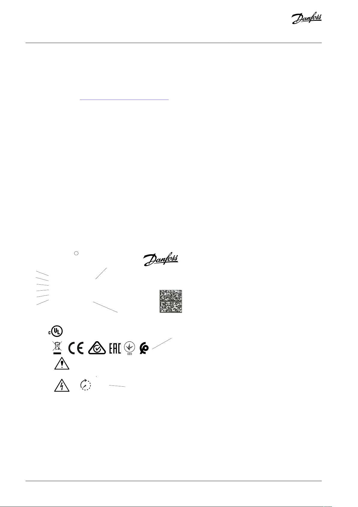
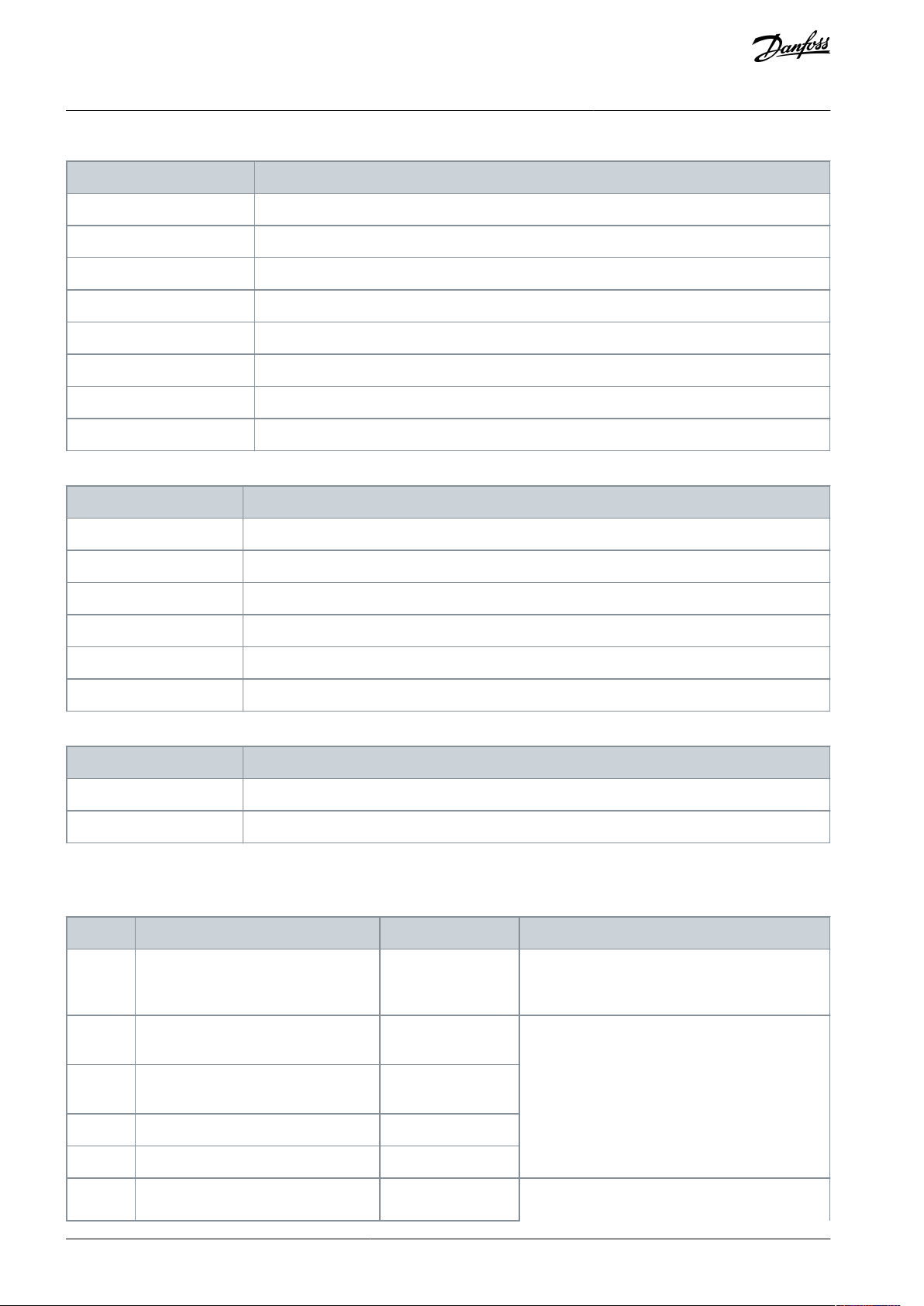
Illustration 1: Nameplate Example
AN354546796134en-000201 / 130R09542 | Danfoss A/S © 2021.05
Page 4

1
Type code
2
Code number
3
Serial number
4
Power rating
5
Input voltage, frequency, and current (at low/high
voltages)
6
Output voltage, frequency, and current (at low/high
voltages)
7
Enclosure size and IP rating
8
Maximum ambient temperature
9
Certifications
10
Discharge time (Warning)
VLT®AutomationDrive EZ FC 321
Installation Guide
N O T I C E
Do not remove the nameplate from the drive (loss of warranty).
Overview
AN354546796134en-000201 / 130R0954 | 3Danfoss A/S © 2021.05
Page 5
NOTE! Download the English and French product guides with applicable safety, warning and caution information from https://
www.danfoss.com/en/service-and-support/.
REMARQUE Vous pouvez télécharger les versions anglaise et française des guides produit contenant l'ensemble des informations
de sécurité, avertissements et mises en garde applicables sur le site https://www.danfoss.com/en/service-and-support/.
VLT®AutomationDrive EZ FC 321
Installation Guide
Safety Instructions
2 Safety Instructions
2.1 Overview
This Safety chapter only relates to installing the drive. When programming or operating the drive, refer to the Application Guide or
Programming Guide for applicable safety instructions. To install this product safely:
•
Check that the content of the delivery is correct and complete.
•
Never install or start up damaged units. File a complaint immediately to the shipping company, if you receive a damaged unit.
•
Follow the instructions provided in this installation guide.
•
Make sure that all personnel working on or with the drive have read and understood this guide and any additional product
manuals. Contact Danfoss if you are unclear of the given information, or if you are missing information.
2.2 Target Group and Necessary Qualifications
Correct and reliable transport, storage, installation, operation, and maintenance are required for the trouble-free and safe operation
of the drive. Only skilled personnel are allowed to perform all related activities for these tasks. Skilled personnel are defined as
properly trained staff, who are familiar with and authorized to install, commission, and maintain equipment, systems, and circuits in
accordance with pertinent laws and regulations. Also, the skilled personnel must be familiar with the instructions and safety measures described in this manual and the other product-specific manuals. If you are not a skilled electrician, do not perform any electrical installation, and troubleshooting activities.
2.3 Safety Symbols
The following symbols are used in this manual:
D A N G E R
Indicates a hazardous situation which, if not avoided, will result in death or serious injury.
W A R N I N G
Indicates a hazardous situation which, if not avoided, could result in death or serious injury.
C A U T I O N
Indicates a hazardous situation which, if not avoided, could result in minor or moderate injury.
N O T I C E
Indicates information considered important, but not hazard-related (for example, messages relating to property damage).
2.4 General Safety Precautions
For US and Canadian markets:
W A R N I N G
LACK OF SAFETY AWARENESS
This document gives important information on how to prevent injury and damage to the equipment or the system. Ignoring
them can lead to death, serious injury, or severe damage to the equipment.
Make sure to fully understand the dangers and safety measures incurred in the application.
-
AN354546796134en-000201 / 130R09544 | Danfoss A/S © 2021.05
Page 6
Voltage [V]
Minimum waiting time (minutes)
41520
[hp]
200–240
0.34–5.0
7.5–50
60–100
380–500
1.0–10
15–100
125–200
525–600
1.0–10
15–100
–
525–690
––125–200
VLT®AutomationDrive EZ FC 321
Installation Guide
Safety Instructions
W A R N I N G
HAZARDOUS VOLTAGE
AC drives contain hazardous voltage when connected to the AC mains or connected on the DC terminals. Failure to perform
installation, start-up, and maintenance by skilled personnel can result in death or serious injury.
Only skilled personnel must perform installation, start-up, and maintenance.
-
W A R N I N G
DISCHARGE TIME
The drive contains DC-link capacitors, which can remain charged even when the drive is not powered. High voltage can be
present even when the warning indicator lights are off.
Failure to wait the specified time after power has been removed before performing service or repair work can result in death or
serious injury.
Stop the motor.
-
Disconnect AC mains, permanent magnet type motors, and remote DC-link supplies, including battery back-ups, UPS, and
-
DC-link connections to other drives.
Wait for the time specified in the Discharge Time tables for the capacitors to discharge fully before performing any service or
-
repair work.
Measure the voltage level to verify full discharge.
-
Table 1: Discharge Time
W A R N I N G
UNINTENDED START
When the drive is connected to the AC mains, DC supply, or load sharing, the motor may start at any time, causing risk of death,
serious injury, and equipment or property damage. The motor may start by activation of an external switch, a fieldbus command,
an input reference signal from the LCP or LOP, via remote operation using MCT 10 Set-up software, or after a cleared fault condi-
tion.
Press [Off] on the LCP before programming parameters.
-
Disconnect the drive from the mains whenever personal safety considerations make it necessary to avoid unintended motor
-
start.
Check that the drive, motor, and any driven equipment are in operational readiness.
-
INTERNAL FAILURE HAZARD
An internal failure in the drive can result in serious injury when the drive is not properly closed.
Ensure that all safety covers are in place and securely fastened before applying power.
-
C A U T I O N
AN354546796134en-000201 / 130R0954 | 5Danfoss A/S © 2021.05
Page 7
Enclosure size
Protection rating
Dimensions (HxWxD) [in]
Weight [lb]
A2
IP20/Chassis
10.6x3.6x8.7
10.8A3IP20/Chassis
10.6x5.2x8.7
14.6
A5
IP66 - Type 4X
16.6x9.6x7.9
31.5
B1
IP66 - Type 4X
18.9x9.6x10.3
51
B2
IP66 - Type 4X
25.6x9.6x10x3
60
B3
IP20/Chassis
15.8x6.5x9.8
26.5B4IP20/Chassis
20.5x9.1x9.6
52C1IP66 - Type 4X
26.8x12.2x12.3
99C2IP66 - Type 4X
30.4x14.6x13.2
143C3IP20/Chassis
21.7x12.2x13
77C4IP20/Chassis
26x14.6x13
110
D1h
Type 12
35.5x12.8x14.9
136.7
D2h
Type 12
43.6x12.8x14.9
275.6
D3h
IP20/Chassis
35.8x19.8x14.8
136.7
D4h
IP20/Chassis
44.2x14.8x14.8
238.1
VLT®AutomationDrive EZ FC 321
Installation Guide
Safety Instructions
C A U T I O N
HOT SURFACES
The drive contains metal components that are still hot even after the drive has been powered off. Failure to observe the high
temperature symbol (yellow triangle) on the drive can result in serious burns.
Be aware that internal components, such as busbars, may be extremely hot even after the drive has been powered off.
-
Do not touch exterior areas that are marked by the high temperature symbol (yellow triangle). These areas are hot while the
-
drive is in use and immediately after being powered off.
2.5 Lifting the Drive
N O T I C E
LIFTING HEAVY LOAD
The weight of the drive is heavy and failure to follow local safety regulations for lifting heavy weights may cause death, personal
injury, or property damage.
Ensure that the lifting equipment is in proper working condition.
-
Check the weight of the drive and verify that the lifting equipment can safely lift the weight.
-
Always lift the drive using a lifting bar inserted into the lifting eyes. Maximum diameter for the lifting bar: 20 mm (0.8 in).
-
The angle from the top of the drive to the lifting cable: 60° or greater.
-
Test lift the unit approximately 610 mm (24 in) to verify the proper center of gravity lift point. Reposition the lifting point if
-
the unit is not level.
Table 2: Drive Weights and Dimensions
AN354546796134en-000201 / 130R09546 | Danfoss A/S © 2021.05
Page 8

VLT®AutomationDrive EZ FC 321
Installation Guide
Safety Instructions
2.6 Mechanical Installation Precautions
W A R N I N G
EXPLOSIVE ATMOSPHERE
Installing the drive in a potentially explosive atmosphere can lead to death, personal injury, or property damage.
Install the unit in a cabinet outside of the potentially explosive area.
-
Use a motor with an appropriate ATEX protection class.
-
Install a PTC temperature sensor to an ATEX PTC-Thermistor device to monitor the motor temperature.
-
Install short motor cables.
-
Use sine-wave output filters when shielded motor cables are not used.
-
2.7 Electrical Installation Precautions
Before you do electrical work on the drive, lock out and tag out all power sources to the drive.
W A R N I N G
INDUCED VOLTAGE
Induced voltage from output motor cables that run together can charge equipment capacitors, even with the equipment turned
off and locked out/tagged out. Failure to run output motor cables separately or to use shielded cables could result in death or
serious injury.
Run output motor cables separately or use shielded cables.
-
Simultaneously lock out/tag out all the drives.
-
Protective earth connection and RCD requirements
A properly dimensioned protective earth (PE) setup is essential for the safety of the drive system protecting the user against electrical shock. The PE connections of the drive installation ensure that the drive system remains safe preventing that the single fault
currents will generate any hazardous voltages on accessible conductive part, for example, conductive enclosure parts.
The VLT® AutomationDrive EZ FC 321 shall be installed according to the requirement for PE connection and supplementary protective bonding as specified in IEC/EN 60364-5-54 cl. 543 and 544.
For the automatic disconnection, if there is a fault at the motor side, it shall also be ensured that the impedance of the PE connection between drive and motor is sufficiently low to ensure compliance with IEC/EN 60364-4-41 cl. 411 or 415. The impedance is
verified by initial and periodic test according to IEC 60364-4-41.
In some regions, extra local requirements apply and must be adhered to.
The suitability for connection of PE and protective bonding of accessible conductive parts according to IEN/EN 60364-5-54 to the
drive is ensured by following the design according to IEC/EN 61800-5-1.
Where the FC 321 is used as a component inside specific applications, special requirement for proper connection to the PE may
apply, for example, IEC/EN 60204 and IEC/EN 61349-1.
AN354546796134en-000201 / 130R0954 | 7Danfoss A/S © 2021.05
Page 9
VLT®AutomationDrive EZ FC 321
Installation Guide
Safety Instructions
W A R N I N G
ELECTRICAL SHOCK HAZARD - LEAKAGE CURRENT HAZARD >3.5 MA
Leakage currents exceed 3.5 mA. Failure to connect the drive properly to protective earth (PE) can result in death or serious in-
jury.
Ensure reinforced protective earthing conductor according to IEC 60364-5-54 cl. 543.7 or according to local safety regula-
-
tions for high touch current equipment. The reinforced protective earthing of the can be done with:
a PE conductor with a cross-section of at least 10 mm2 (8 AWG) Cu or 16 mm2 (6 AWG) Al
-
an extra PE conductor of the same cross-sectional area as the original PE conductor as specified by IEC 60364-5-54 with a
-
minimum cross-sectional area of 2.5 mm2 (14 AWG) (mechanical protected) or 4 mm2 (12 AWG) (not mechanical protected).
a PE conductor completely enclosed with an enclosure or otherwise protected throughout its length against mechanical
-
damage.
a PE conductor part of a multi-conductor power cable with a minimum PE conductor cross-section of 2.5 mm2 (14 AWG)
-
(permanently connected or pluggable by an industrial connector. The multi-conductor power cable shall be installed with an
appropriate strain relief).
NOTE: In IEC/EN 60364-5-54 cl. 543.7 and some application standards (for example IEC/EN 60204-1), the limit for requiring
-
reinforced protective earthing conductor is 10 mA leakage current.
W A R N I N G
ELECTRICAL SHOCK HAZARD - LEAKAGE CURRENT
Leakage currents can exceed 5%. Failure to ground the drive properly can result in death or serious injury.
When the leakage currents exceed 5%, the protective earth (PE) shall be oversized by one number according to IEC/EN
-
60364-5-54 cl. 543.
Ensure that the minimum size of the ground conductor complies with local safety regulations.
-
W A R N I N G
ELECTRICAL SHOCK AND FIRE HAZARD - RCD COMPLIANCE
The unit can cause a DC fault current in the PE conductor. Failure to use a Type B residual current-operated protective device
(RCD) may lead to the RCD not providing the intended protection and therefore may result in death, fire, or other serious hazard.
When an RCD is used for protection against electrical shock or against fire, only a Type B device is allowed on the supply side.
-
Other precautions
C A U T I O N
THERMISTOR INSULATION
Risk of personal injury or equipment damage.
To meet PELV insulation requirements, use only thermistors with reinforced or double insulation.
-
N O T I C E
EXCESSIVE HEAT AND PROPERTY DAMAGE
Overcurrent can generate excessive heat within the drive. Failure to provide overcurrent protection can result in risk of fire and
property damage.
Other protective devices such as short-circuit protection or motor thermal protection between drive and motor are required
-
for applications with multiple motors.
Input fusing is required to provide short circuit and overcurrent protection. If fuses are not factory-supplied, the installer
-
must provide them. See 4.11 Fuses and Circuit Breakers for fuse specifications.
AN354546796134en-000201 / 130R09548 | Danfoss A/S © 2021.05
Page 10

VLT®AutomationDrive EZ FC 321
Installation Guide
Safety Instructions
N O T I C E
PROPERTY DAMAGE
Protection against motor overload is not included in the default setting. The ETR function provides class 20 motor overload pro-
tection. Failure to set the ETR function means that motor overload protection is not provided and property damage can occur if
the motor overheats.
Enable the ETR function. See the application guide for more information.
-
2.8 Safe Operation
When operating the unit, refer to the Programming Guide and Application Guide for guidance and all applicable safety instructions.
•
The drive is not suitable as the only safety device in the system. Make sure that additional monitoring and protection devices on
drives, motors, and accessories are installed according to the regional safety guidelines and accident prevention regulations.
•
Keep all doors, covers, and terminal boxes closed and securely fastened during operation.
AN354546796134en-000201 / 130R0954 | 9Danfoss A/S © 2021.05
Page 11
Location
Enclosure sizes
A2–A5
B1/B3
B2/B4
C1/C3
C2/C4
D1h/D3h
Mains terminals [in-lb]
4.4–5.3
15.9
39.8
89
124 (up to 3 AWG)
212 (over 3 AWG)
168/335
(1)
Motor terminals [in-lb]
4.4–5.3
15.9
39.8
89
124 (up to 3 AWG)
212 (over 3 AWG)
168/335
(1)
Ground terminals [in-lb]
–
17.7–26.6
17.7–26.6
17.7–26.6
17.7–26.6
84/169
(2)
Brake terminals [in-lb]
4.4–5.3
15.9
39.88912484Relay terminals [in-lb]
–
4.4–5.3
4.4–5.3
4.4–5.3
4.4–5.3
4
a
a
e30bd528.10
Enclosure
A2–A3, A5
B1–B4
C1, C3
C2, C4
D1h–D4h
a [in]
3.9
7.8
7.8
8.9
8.9
VLT®AutomationDrive EZ FC 321
Installation Guide
3 Mechanical Installation
3.1 Connection Tightening Torques
Table 3: Tightening Torque for Cables
Mechanical Installation
1
Bolt size M10/M12
2
Bolt size M8/M10
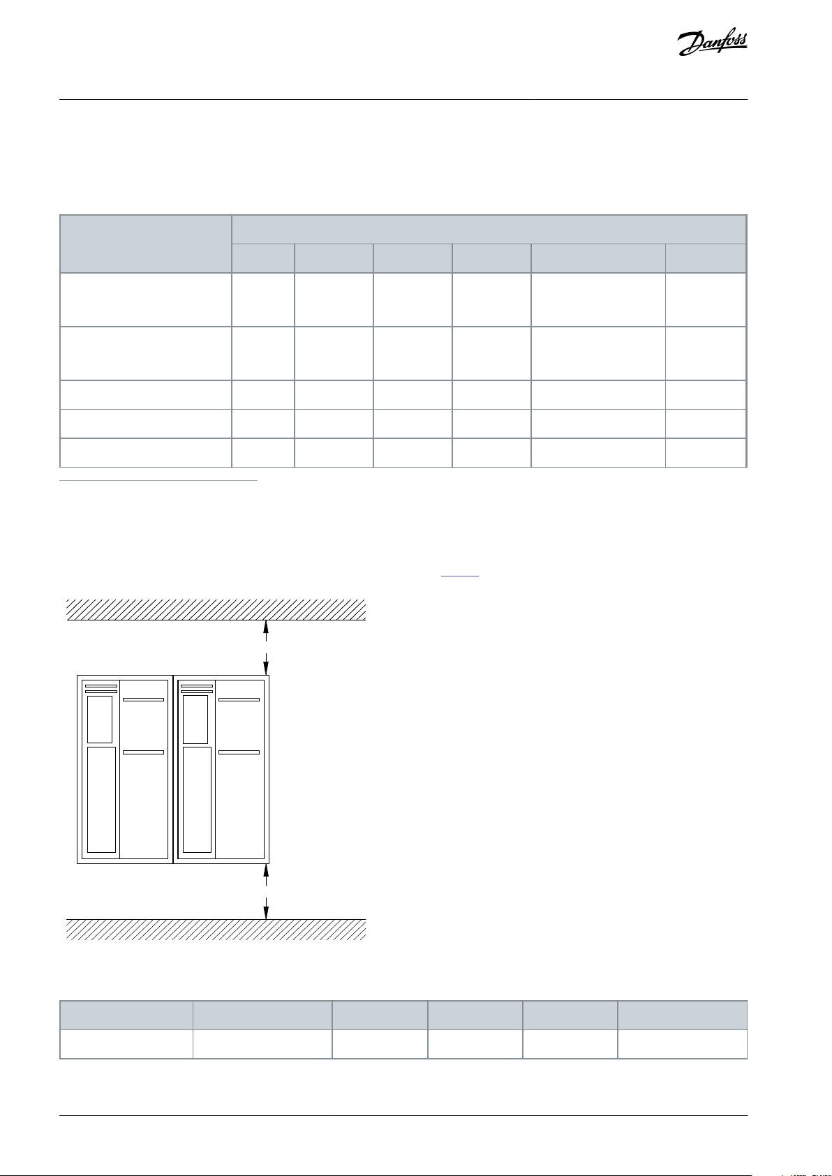
3.2 Cooling
Ensure that top and bottom clearance for air cooling is provided. See
•
Table 4 for clearance requirements.
Illustration 2: Top and Bottom Cooling Clearance
Table 4: Minimum Airflow Clearance Requirements
AN354546796134en-000201 / 130R095410 | Danfoss A/S © 2021.05
Page 12
e30bd504.11
VLT®AutomationDrive EZ FC 321
Installation Guide
3.3 Mounting
Procedure
1.
Ensure that the strength of the mounting location supports the unit weight.
The drive allows side-by-side installation.
2.
Place the unit as near to the motor as possible. Keep the motor cables as short as possible.
3.
Mount the unit vertically to a solid flat surface or to the optional backplate to provide cooling airflow.
4.
Use the slotted mounting holes on the unit for wall mount, when provided.
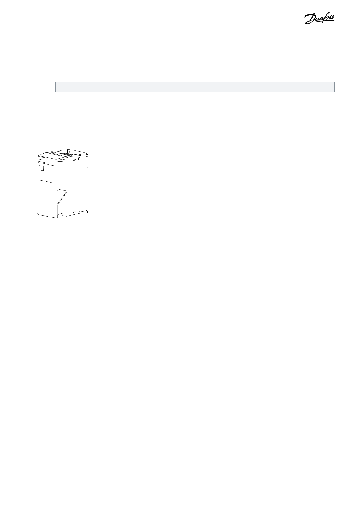
3.3.1 Mounting with Mounting Plate and Railings
A mounting plate is required when mounted on railings.
Mechanical Installation
Illustration 3: Proper Mounting with Mounting Plate
3.4 Preparing Cable Entry Holes
Procedure
1.
Remove cable entry from the drive. Avoid that foreign parts fall into the drive when removing the knockouts.
2.
Support the cable entry where the knockout is to be removed.
3.
Remove the knockout with a strong mandrel and a hammer.
4.
Remove burrs from the hole.
5.
Mount the cable entry on the drive.
AN354546796134en-000201 / 130R0954 | 11Danfoss A/S © 2021.05
Page 13

VLT®AutomationDrive EZ FC 321
Installation Guide
Electrical Installation
4 Electrical Installation
4.1 EMC-compliant Installation
To obtain an EMC-compliant installation, refer to the wiring schematic (see Illustration 5) and follow the electrical installation instructions.
Also, remember to practice the following:
•
When using relays, control cables, a signal interface, fieldbus, or brake, connect the shield to the enclosure at both ends. If the
ground path has high impedance, is noisy, or is carrying current, break the shield connection on 1 end to avoid ground current
loops.
•
Convey the currents back to the unit using a metal mounting plate. Ensure good electrical contact from the mounting plate
through the mounting screws to the drive chassis.
•
Use shielded cables for motor output cables. An alternative is unshielded motor cables within metal conduit.
•
Ensure that motor and brake cables are as short as possible to reduce the interference level from the entire system.
•
Provide a minimum 200 mm (7.9 in) separation between mains input, motor cables, and control cables.
•
For communication and command/control lines, follow the particular communication protocol standards. For example, USB
must use shielded cables, but RS485/ethernet can use shielded UTP or unshielded UTP cables.
•
Ensure that all control terminal connections are PELV.
N O T I C E
TWISTED SHIELD ENDS (PIGTAILS)
Twisted shield ends increase the shield impedance at higher frequencies, which reduces the shield effect and increases the leak-
age current.
Use integrated shield clamps instead of twisted shield ends.
-
N O T I C E
SHIELDED CABLES
If shielded cables or metal conduits are not used, the unit and the installation do not meet regulatory limits on radio frequency
(RF) emission levels.
N O T I C E
EMC INTERFERENCE
Failure to isolate power, motor, and control cables can result in unintended behavior or reduced performance.
Use shielded cables for motor and control wiring.
-
Provide a minimum 200 mm (7.9 in) separation between mains input, motor cables, and control cables.
-
N O T I C E
INSTALLATION AT HIGH ALTITUDE
There is a risk for overvoltage. Isolation between components and critical parts could be insufficient and may not comply with
PELV requirements.
Use external protective devices or galvanic isolation. For installations above 2000 m (6500 ft) altitude, contact Danfoss re-
-
garding protective extra low voltage (PELV) compliance.
N O T I C E
PROTECTIVE EXTRA LOW VOLTAGE (PELV) COMPLIANCE
Prevent electric shock by using PELV electrical supply and complying with local and national PELV regulations.
AN354546796134en-000201 / 130R095412 | Danfoss A/S © 2021.05
Page 14

L1
L2L3PEL1L2L3PEPEu
v
w
2
1
3
5
IEC 60309
16
17
18
14
12
8
7
10
9
4
11
13
446
15
90
+DC
BR-
B
M
AINS
L1 L2 L3
91 92 93
RELA
Y 1 RELA
Y 2
99
- L
C -
UV
W
MO
T
OR
VLT®AutomationDrive EZ FC 321
Installation Guide
Electrical Installation
Illustration 4: Example of Proper EMC Installation
AN354546796134en-000201 / 130R0954 | 13Danfoss A/S © 2021.05
Page 15

1
Programmable logic controller (PLC)
2
Minimum 16 mm2 (6 AWG) equalizing cable
3
Control cables
4
Minimum 200 mm (7.9 in) between control cables,
motor cables, and mains cables
5
Mains supply options, see IEC/EN 61800-5-1
6
Bare (unpainted) surface
7
Star washers
8
Brake cable (shielded) – not shown, but same
gounding principle applies as for motor cable
9
Motor cable (shielded)
10
Mains cable (unshielded)
11
Output contactor, and so on.
12
Cable insulation stripped
13
Common ground busbar. Follow local and national
requirements for cabinet grounding.
14
Brake resistor
15
Terminal box
16
Connection to motor
17
Motor
18
EMC cable gland
VLT®AutomationDrive EZ FC 321
Installation Guide
Electrical Installation
N O T I C E
EMC INTERFERENCE
Use shielded cables for motor and control wiring, and separate cables for input power, motor wiring, and control wiring. Failure
to isolate power, motor, and control cables can result in unintended behavior or reduced performance. Minimum 200 mm (7.9 in)
clearance is required between power, motor, and control cables.
AN354546796134en-000201 / 130R095414 | Danfoss A/S © 2021.05
Page 16

e30bj012.10
––
Motor
Analog Output
ON=Terminated
OFF=Open
91 (L1)
92 (L2)
93 (L3)
PE
88 (-)
89 (+)
53 (A IN)
54 (A IN)
37 (D IN)
1)
18 (D IN)
10
V DC
15 mA 130/200 mA
+ - + -
(U) 96
(V) 97
(W) 98
(PE) 99
(P RS485) 68
(N RS485) 69
0 V
5V
S801
0/4–20 mA
RS-485
03
240 V AC, 2 A
24 V DC
02
01
05
04
06
24
V (NPN)
0 V (PNP)
0 V (PNP)
24
V (NPN)
19 (D IN)
24
V (NPN)
0 V (PNP)
24
V
0
V
24 V (PNP)
24 V (NPN)
(D IN/OUT
)
1)
0 V
24
V
29
24
V (NPN)
0 V (PNP)
0
V (PNP)
24 V (NPN)
33 (D IN)
32 (D IN)
1 2
ON
S201
ON
21
S202
ON=0/4–20 mA
95
P 5-00
21
ON
S801
(R+) 82
(R-) 81
: Chassis
240 V AC, 2 A
400 V AC, 2 A
: PE
3-phase
power
input
+10 V DC
DC bus
0/-10 V DC to
+10 V DC
0/4–20 mA
0/-10 V DC to
+10 V DC
0/4–20 mA
50 (+10 V OUT)
55 (COM A IN)
12 (+24 V OUT)
13 (+24 V OUT)
20 (COM D IN)
27 (D IN/OUT)
Switch mode
power supply
Brake
resistor
Relay 1
Relay 2
(COM A OUT) 39
(A OUT) 42
: Ground
: Ground 1
: Ground 2
(COM RS485) 61
2)
RS485
interface
OFF=0/-10 V DC
to +10 V DC
Type of cable
Maximum cross-section [AWG]
Minimum cross-section [AWG]
Flexible wire without cable end sleeves
1624Rigid wire without cable end sleeves
1624Flexible wire with cable end sleeves
1824Flexible wire with cable end sleeves with collar
20
24
VLT®AutomationDrive EZ FC 321
Installation Guide
Electrical Installation
Illustration 5: Wiring Schematic
4.2 Cable Specifications
WIRE TYPE AND RATINGS
All wiring must comply with local and national regulations regarding cross-section and ambient temperature requirements. For
power connections, minimum 167 °F rated copper wire is recommended.
Table 5: Control Cable Specifications
N O T I C E
AN354546796134en-000201 / 130R0954 | 15Danfoss A/S © 2021.05
Page 17
Enclosure size
Maximum cable size [AWG], mains, motor, brake
A2–A5
12
B1/B3
7
B2/B4
2C11/0C31/0
C2/C4
4/0
D1h/D3h
3/0
D2h/D4h
2x3/0
Enclosure size
Maximum cable size [AWG], mains, motor, and brake
A3/A5
12
B1/B3
7
B2/B4
2C11/0C31/0
C2/C4
4/0
Enclosure size
Maximum cable size [AWG], mains, motor, and brake
D1h/D3h
3/0
D2h/D4h
2x400
Terminal
Parameter
Default setting
Description
12, 13
–
+24 V DC
+24 V DC supply voltage for digital inputs and external transducers. Maximum output current
200 mA for all 24 V loads.
18
Parameter 5-10 Terminal 18 Digital Inputs
[8] Start
Digital inputs
19
Parameter 5-11 Terminal 19 Digital Inputs
[0] No operation
32
Parameter 5-14 Terminal 32 Digital Input
[0] No operation
33
Parameter 5-15 Terminal 33 Digital Input
[0] No operation
27
Parameter 5-12 Terminal 27 Digital Input
[2] Coast inverse
For digital input or output. Default setting is input.
VLT®AutomationDrive EZ FC 321
Installation Guide
Table 6: Power Cable Sizes for 104 °F Ambient Temperature, 200–240 V and 380–500 V
Table 7: Power Cable Sizes for 104 °F Ambient Temperature, 525–600 V
Electrical Installation
Table 8: Power Cable Sizes for 104 °F Ambient Temperature, 525–690 V
4.3 Terminal Descriptions
Table 9: Digital Inputs/Outputs
AN354546796134en-000201 / 130R095416 | Danfoss A/S © 2021.05
Page 18

Terminal
Parameter
Default setting
Description
29
Parameter Terminal 29 Digital Input
[14] Jog
20––
Common for digital inputs and 0 V potential for
24 V supply.
37–Safe Torque Off (STO)
Safe input. Used for STO.
Terminal
Parameter
Default setting
Description
39––
Common for analog output.
42
Parameter 6-50 Terminal 42
Output
Speed 0–high limit
Programmable analog output. 0–20 mA or 4–20 mA at a maximum of 500 Ω.
50–+10 V DC
10 V DC analog supply voltage potentiometer or thermistor.
15 mA maximum.
53
Parameter group 6-1* Analog
Input 1
Reference
Analog input. For voltage or current. Switches A53 and A54 select mA or V.
54
Parameter group 6-1* Analog
Input 2
Feedback
55––
Common for analog input.
Terminal
Parameter
Default
setting
Description
61––
Integrated RC-filter for cable shield. ONLY for connecting the shield if
EMC problems occur.
68 (+)
Parameter group 8-3* FC Port
Settings
–
RS485 interface. A control card switch is provided for termination resistance.
69 (-)
Parameter group 8-3* FC Port
Settings
–
Terminal
Parameter
Default setting
Description
01, 02, 03
Parameter 5-40 Function Relay [0]
[9] Alarm
Form C relay output. For AC or DC voltage and resistive or inductive loads.
04, 05, 06
Parameter 5-40 Function Relay [1]
[5] Running
VLT®AutomationDrive EZ FC 321
Installation Guide
Table 10: Analog Inputs/Outputs
Electrical Installation
Table 11: Serial Communication
Table 12: Relays
4.4 Connecting the Control Cables to the Control Terminals
The control terminal connectors can be unplugged from the drive for convenience when wiring. Either solid or flexible wire can be
connected to the control terminals.
ELECTRICAL INTERFERENCE
Minimize interference by keeping control wires as short as possible and separate from high-power cables.
1.
Strip 10 mm (0.4 in) of the outer plastic layer from the end of the wire.
N O T I C E
AN354546796134en-000201 / 130R0954 | 17Danfoss A/S © 2021.05
Page 19

e30bd546.12
10 mm
(0.4 in)
12 13 18 19 27
29 32 33
12 13 18 37
e30ba155.12
322719 29 33 20
P 5-12 [0]
P 5-10 [8]
Start/Stop
+24V
Speed
Safe Stop
Start/Stop
[18]
VLT®AutomationDrive EZ FC 321
Installation Guide
2.3.Insert the control wire into the appropriate terminals.
Pull gently on the wire to ensure that the contact is firmly established.
Loose control cable can cause equipment faults or reduced performance.
4.5 Start/Stop
Terminal 18 = Parameter 5-10 Terminal 18 Digital Input [8] Start.
Terminal 27 = Parameter 5-12 Terminal 27 Digital Input [0] No operation (Default [2] Coast inverse).
Terminal 37 = Safe Torque Off.
Electrical Installation
Illustration 6: Start/Stop
4.6 Pulse Start/Stop
Terminal 18 = Parameter 5-10 Terminal 18 Digital Input [9] Latched start.
Terminal 27 = Parameter 5-12 Terminal 27 Digital Input [6] Stop inverse.
Terminal 37 = Safe Torque Off.
AN354546796134en-000201 / 130R095418 | Danfoss A/S © 2021.05
Page 20

12
13
18 37
e30ba156.12
32
2719
29 33 20
P 5 - 12 [6]
P 5 - 10[9]
+24V
Speed
Start
Stop inverse Safe Stop
Start (18)
Start (27)
12
18
27
29
32
37
+24V
Par. 5-10
Par. 5-12
Par. 5-13
Par. 5-14
e30ba021.13
VLT®AutomationDrive EZ FC 321
Installation Guide
Electrical Installation
Illustration 7: Pulse Start/Stop
4.7 Speed Up/Speed Down
Terminal 18 = Parameter 5-10 Terminal 18 Digital Input [8] Start.
Terminal 27 = Parameter 5-12 Terminal 27 Digital Input [19] Freeze reference.
Terminal 37 = Safe Torque Off.
Terminal 29 = Parameter 5-13 Terminal 29 Digital Input [21] Speed up.
Terminal 32 = Parameter 5-14 Terminal 32 Digital Input [22] Speed down.
Illustration 8: Speed Up/Speed Down
AN354546796134en-000201 / 130R0954 | 19Danfoss A/S © 2021.05
Page 21

e30ba154.11
55 50
39 42 53 54
Speed RP M
P 6-15
1 k
+10V/30mA
R
ef . v oltage
P 6-11 10V
VLT®AutomationDrive EZ FC 321
Installation Guide
4.8 Potentiometer Reference
Voltage reference via a potentiometer
Reference source 1 = [1] Analog input 53 (default).
Terminal 53, low voltage = 0 V.
Terminal 53, high voltage = 10 V.
Terminal 53, low reference/feedback = 0 RPM.
Terminal 53, high reference/feedback = 1500 RPM.
Switch S201 = OFF (U)
Electrical Installation
Illustration 9: Potentiometer Reference
4.9 Connecting the Motor
W A R N I N G
INDUCED VOLTAGE
Induced voltage from output motor cables that run together can charge equipment capacitors, even with the equipment turned
off and locked out/tagged out. Failure to run output motor cables separately or to use shielded cables could result in death or
serious injury.
Run output motor cables separately or use shielded cables.
-
Simultaneously lock out/tag out all the drives.
-
•
Run output motor cables separately or
•
Use shielded cables.
•
Comply with local and national electrical codes for cable sizes. For maximum wire sizes, see 4.2 Cable Specifications.
•
Follow motor manufacturer wiring requirements.
•
Motor wiring knockouts or access panels are provided at the base of IP55 (NEMA 12) units.
•
Do not wire a starting or pole-changing device (for example a Dahlander motor or slip ring asynchronous motor) between the
drive and the motor.
4.9.1 Grounding the Cable Shield
Procedure
1.
Strip a section of the outer cable insulation.
2.
Position the stripped wire under the cable clamp to establish mechanical fixation and electrical contact between the cable
shield and ground.
AN354546796134en-000201 / 130R095420 | Danfoss A/S © 2021.05
Page 22

e30bd531.11
U
V
W
96
97
98
VLT®AutomationDrive EZ FC 321
Installation Guide
3.
Connect the ground wire to the nearest grounding terminal.
Electrical Installation
4.
Connect the 3-phase motor wiring to terminals 96 (U), 97 (V), and 98 (W).
5.
Torque-tighten the terminals, see Table 3.
Example
Mains input, motor, and grounding for basic drives. Actual configurations vary with unit types and optional equipment.
AN354546796134en-000201 / 130R0954 | 21Danfoss A/S © 2021.05
Page 23

+DC
BR-
B
M A I N S
L1 L2 L3
91 92 93
RELAY 1 RELAY 2
99
U V W
MOTOR
99
130BF048.11
VLT®AutomationDrive EZ FC 321
Installation Guide
Electrical Installation
Illustration 10: Example of Motor, Mains, and Ground Wiring
4.10 Connecting AC Mains
•
Size the wiring based on the input current of the drive. For maximum wire sizes, see 4.2 Cable Specifications.
•
Comply with local and national electrical codes for cable sizes.
4.10.1 Connecting the Drive to Mains
Procedure
1.
Connect the 3-phase AC input power wiring to terminals L1, L2, and L3.
2.
Depending on the configuration of the equipment, connect the input power to the mains input terminals or the input disconnect.
3.
Ground the cable.
4.
When supplied from an isolated mains source (IT mains or floating delta) or TT/TN-S mains with a grounded leg (grounded
delta), ensure that parameter 14-50 RFI Filter is set to [0] Off. This setting prevents damage to the DC link and reduces
ground capacity currents in accordance with IEC 61800-3.
AN354546796134en-000201 / 130R095422 | Danfoss A/S © 2021.05
Page 24

L 1
L 2
L 3
91
92
93
e130bt336.11
Enclosure
Power [hp]
Recommended fuse
size
Recommended maximum fuse
Recommended circuit breaker
Eaton/Moeller
Maximum trip level [A]A20.34–2.0
gG-10
gG-25
PKZM0-25
25
3.0
gG-16
A3
4.0
gG-16
gG-32
PKZM0-25
25
5.0
gG-20
A5
0.34–2.0
gG-10
gG-32
PKZM0-25
25
3.0–4.0
gG-16
5.0
gG-20
B1
7.5
gG-25
gG-80
PKZM4-63
63
VLT®AutomationDrive EZ FC 321
Installation Guide
Illustration 11: Connecting to AC Mains
4.11 Fuses and Circuit Breakers
Electrical Installation
4.11.1 Fuse Recommendations
Fuses ensure that possible damage to the drive is limited to damages inside the unit. Danfoss recommends fuses and/or circuit
breakers on the supply side as protection. For further information, see the application guide Fuses and Circuit Breakers.
N O T I C E
Use of fuses on the supply side is mandatory for IEC 60364 (CE) and NEC 2009 (UL) compliant installations.
Recommendations
•
gG type fuses.
•
Eaton/Moeller type circuit breakers. For other circuit breaker types, ensure that the energy into the drive is equal to or lower
than the energy provided by Eaton/Moeller types.
For further information, see the application guide Fuses and Circuit Breakers.
The recommended CE and UL compliant fuses are suitable for use on a circuit capable of 100000 A
the drive voltage rating. With the proper fusing, the drive short circuit current rating (SCCR) is 100000 A
4.11.2 CE Compliance
Table 13: 200–240 V, Enclosure Sizes A, B, C, and D
(symmetrical), depending on
rms
.
rms
AN354546796134en-000201 / 130R0954 | 23Danfoss A/S © 2021.05
Page 25

Enclosure
Power [hp]
Recommended fuse
size
Recommended maximum fuse
Recommended circuit breaker
Eaton/Moeller
Maximum trip level [A]
10.0
gG-32
B2
15.0
gG-50
gG-100
NZMB1-A100
100B37.5
gG-25
gG-63
PKZM4-50
50B410
gG-32
gG-125
NZMB1-A100
100
15
gG-50
20
gG-63
C1
20
gG-63
gG-160
NZMB2-A200
160
25
gG-80
30
gG-100
aR-160
C2
40
aR-160
aR-200
NZMB2-A250
250
50
aR-200
aR-250
C3
25
gG-80
gG-150
NZMB2-A200
150
30
aR-125
aR-160
C4
40
aR-160
aR-200
NZMB2-A250
250
50
aR-200
aR-250
D1h/D3h
60
aR-350
aR-350
––75
aR-400
aR-400
––D2h/D4h
100
aR-550
aR-550
–
–
Enclosure
Power [hp]
Recommended fuse
size
Recommended maximum fuse
Recommended circuit breaker
Eaton/Moeller
Maximum trip
level [A]
A2
0.5–4.0
gG-10
gG-25
PKZM0-25
25
5.0
gG-16
A3
7.5–10
gG-16
gG-32
PKZM0-25
25A50.5–4.0
gG-10
gG-32
PKZM0-25
25
5.0–10
gG-16
B1
15–20
gG-40
gG-80
PKZM4-63
63B225
gG-50
gG-100
NZMB1-A100
100
30
gG-63
B3
15–20
gG-40
gG-63
PKZM4-50
50B425
gG-50
gG-125
NZMB1-A100
100
30
gG-63
VLT®AutomationDrive EZ FC 321
Installation Guide
Electrical Installation
Table 14: 380–500 V, Enclosure Sizes A, B, C, and D
AN354546796134en-000201 / 130R095424 | Danfoss A/S © 2021.05
Page 26

Enclosure
Power [hp]
Recommended fuse
size
Recommended maximum fuse
Recommended circuit breaker
Eaton/Moeller
Maximum trip
level [A]
40
gG-80
C1
40
gG-80
gG-160
NZMB2-A200
160
50
gG-100
60
gG-160
C2
75
aR-200
aR-250
NZMB2-A250
250
100
aR-250
C3
50
gG-100
gG-150
NZMB2-A200
150
60
gG-160
gG-160
C4
75
aR-200
aR-250
NZMB2-A250
250
100
aR-250
D1h/D3h
125
aR-315
aR-315
––150
aR-350
aR-350
––200
aR-400
aR-400
–
–
Enclosure
Power [hp]
Recommended fuse
size
Recommended maximum fuse
Recommended circuit breaker
Eaton/Moeller
Maximum trip level [A]A21.0-5.0
gG-10
gG-25
PKZM0-25
25A37.5
gG-10
gG-32
PKZM0-25
25
10
gG-16
A5
7.5
gG-10
gG-32
PKZM0-25
25
10
gG-16
B1
15
gG-25
gG-80
PKZM4-63
63
20
gG-32
25
gG-40
B2
30
gG-50
gG-100
NZMB1-A100
100
40
gG-63
B3
15
gG-25
gG-63
PKZM4-50
50
20
gG-32
B4
25
gG-40
gG-125
NZMB1-A100
100
30
gG-50
40
gG-63
C1
50
gG-63
gG-160
NZMB2-A200
160
VLT®AutomationDrive EZ FC 321
Installation Guide
Electrical Installation
Table 15: 525–600 V, Enclosure Sizes A, B, C, and D
AN354546796134en-000201 / 130R0954 | 25Danfoss A/S © 2021.05
Page 27

Enclosure
Power [hp]
Recommended fuse
size
Recommended maximum fuse
Recommended circuit breaker
Eaton/Moeller
Maximum trip level [A]60gG-100
60
aR-160
aR-250
C2
100
aR-200
aR-250
NZMB2-A250
250C350
gG-63
gG-150
NZMB2-A200
150
60
gG-100
gG-150
NZMB2-A200
C4
75
aR-160
aR-250
NZMB2-A250
250
100
aR-200
Enclosure
Power [hp]
Recommended fuse size
Recommended maximum fuse
D1h/D3h
125
aR-315
aR-315
150
aR-315
aR-315
200
aR-315
aR-315
UL class
Fuse overload characteristics
Interrupting rating
[A]
AC voltage rating
[V]
Available ampere rating
RK1
Ultra fast-acting, current limiting/time delay
200.000
250
600
1–600
T
Fast-acting
200.000
300
600
1–1.200
J
Fast-acting
200.000
600
1–600
CC
Fast-acting
200.000
600
5–30
VLT®AutomationDrive EZ FC 321
Installation Guide
Table 16: 525–690 V, Enclosure Size D
Electrical Installation
4.11.3 UL Compliance
Fuse classification for UL Compliance
N O T I C E
UL COMPLIANCE
To comply with NEC 2017, it is mandatory to use fuses or circuit breakers. Danfoss recommends using a selection of the fuses
listed in the following tables. These fuses are suitable for use on a circuit capable of delivering 100000 A
500 V, or 600 V depending on the drive voltage rating. With the proper fusing, the drive short-circuit current rating (SCCR) is
100000 A
For semiconductor fuse types, the drive controller and the overcurrent protection device must be integrated within the same overall assembly.
Table 17: UL Fuse Classification Chart
rms
.
(symmetrical), 240 V,
rms
AN354546796134en-000201 / 130R095426 | Danfoss A/S © 2021.05
Page 28

Class fuses
Semiconductor fuses
Power [hp]
RK1/J/T [A]
CC [A]
SIBA
Littelfuse
Ferraz Shawmut (Mersen)
Bussmann (Eaton)
0.34–0.5
555017906-005
––FWX-5
0.75–1.5
10105017906-010
––FWX-10
2.01515
5017906-016
––FWX-15
3.02020
5017906-020
––FWX-20
4.02525
5017906-025
––FWX-25
5.03030
5012406-032
––FWX-30
7.550–
5014006-050
––FWX-50
1060–
5014006-063
––FWX-60
1580–
5014006-080
––FWX-80
20–25
125–2028220-125
––FWX-125
30
150–2028220-150
L25S-150
A25X-150
FWX-150
40
200–2028220-200
L25S-200
A25X-200
FWX-200
50
250–2028220-250
L25S-250
A25X-250
FWX-250
Class fuses
Semiconductor fuses
Power [hp]
RK1/J/T [A]
CC [A]
SIBA
Littelfuse
Ferraz Shawmut (Mersen)
Bussmann (Eaton)
0.5–1.5
665017906-006
––FWH-6
2.0–3.0
10105017906-010
––FWH-10
4.01515
5017906-016
––FWH-15
5.02020
5017906-020
––FWH-20
7.52525
5017906-025
––FWH-25
103030
5012406-032
––FWH-30
1540–
5014006-040
––FWH-40
2050–
5014006-050
––FWH-50
2560–
5014006-063
––FWH-60
3080–
2028220-100
––FWH-80
40
100–2028220-125
––FWH-100
50
125–2028220-125
––FWH-125
60
150–2028220-160
––FWH-150
75
200–2028220-200
L50-S-225
A50-P-225
FWH-200
100
250–2028220-250
L50-S-250
A50-P-250
FWH-250
VLT®AutomationDrive EZ FC 321
Installation Guide
Table 18: Recommended Maximum UL Fuse Class, Voltage Range 3x200–240 V, Enclosure Sizes A, B, and C
Electrical Installation
Table 19: Recommended Maximum UL Fuse Class, Voltage Range 380–500 V, Enclosure Sizes A, B, and C
AN354546796134en-000201 / 130R0954 | 27Danfoss A/S © 2021.05
Page 29

Class fuses
Semiconductor fuses
Power [hp]
RK1/J/T [A]
CC [A]
SIBA
1.5
5
(1)
5
5017906-005
2.0–3.0
10105017906-010
4.01515
5017906-016
5.02020
5017906-020
7.52525
5017906-025
103030
5017906-030
1535–
5014006-040
2045–
5014006-050
2550–
5014006-050
3060–
5014006-063
4080–
5014006-080
50
100–5014006-100
60
125–2028220-125
75
150–2028220-150
100
175–2028220-200
Enclosure
size
Enclosure
(1)
Voltage [V]
Power [hp]
HO
Maximum interrupting
rating for listed circuit
breakers
Maximum
ampere
rating
[A]
Further information
A4/A5
Type 4X
380–500
(T5)
0.5, 0.75,
1.0, 1.5, 2.0,
3.0, 4.0, 5.0,
7.5, 10
100 kA (at
480 V)
25
Any UL 489 listed circuit breaker, maximum
25 A.
A5
Type 4X
200–240 V
(T2)
4.0, 5.0
Specific type
25
ABB MS165-25 480V/277Y 65 kA.
A5
Type 4X
380–500 V
(T5)
7.5, 10
Specific type
25
ABB MS165-25 480V/277Y 65 kA.
A5
Type 4X
525–600 V
(T6)
5.0, 7.5, 10
Specific type
25
ABB MS165-25 600V/347Y 30 kA.
VLT®AutomationDrive EZ FC 321
Installation Guide
Table 20: Recommended Maximum UL Fuse Class, Voltage Range 525–690 V, Enclosure Sizes A, B, and C
Electrical Installation
1
Bussmann Class T allowed up to 6 A.
UL Compliance only for 525–600 V.
Table 21: UL Approved Branch Circuit Protection
N O T I C E
AN354546796134en-000201 / 130R095428 | Danfoss A/S © 2021.05
Page 30

Enclosure
size
Enclosure
(1)
Voltage [V]
Power [hp]
HO
Maximum interrupting
rating for listed circuit
breakers
Maximum
ampere
rating
[A]
Further information
B1
Type 4X
200–240 V
(T2)
7.5, 10
Specific type
40–54
ABB MS165-54 480V/277Y 65 kA.
B1
Type 4X
380–500 V
(T5)
15, 20
Specific type
40–54
ABB MS165-54 480V/277Y 65 kA.
B1
Type 4X
380–500 V
(T5)
15, 20
100 kA
60
Any UL 489 circuit breaker type with maximum
interrupt rating and maximum ampere rating
in list.
B1
Type 4X
525–600 V
(T6)
15, 20
50 kA
40
Any UL 489 circuit breaker type with maximum
interrupt rating and maximum ampere rating
in list.
B2
Type 4X
380–500 V
(T5)
25, 30
100 kA
100
Any UL 489 circuit breaker type with maximum
interrupt rating and maximum ampere rating
in list
B2
Type 4X
525–600 V
(T6)
25, 30
35 kA
60
any UL 489 circuit breaker type with maximum
interrupt rating and maximum ampere rating
in list.
C1
Type 4X
380–500 V
(T5)
40, 50, 60
100 kA
200
Any UL 489 circuit breaker type with maximum
interrupt rating and maximum ampere rating
in list.
C2
Type 4X
380–500 V
(T5)
75, 100
100 kA
250
Any UL 489 circuit breaker type with maximum
interrupt rating and maximum ampere rating
in list.
VLT®AutomationDrive EZ FC 321
Installation Guide
Electrical Installation
1
Only Type 4X enclosures can be used. Not valid for Open type (IP20) units.
AN354546796134en-000201 / 130R0954 | 29Danfoss A/S © 2021.05
Page 31

Enclosure
IP20/Chassis, IP54/NEMA 12, IP66/Type 4X
Vibration test
1.0 g
Maximum THDv
10%
Maximum relative humidity
5–93 (IEC 721-3-3); Class 3K3 (non-condensing) during operation
Aggressive environment (IEC 60068-2-43) H2S test
Class Kd
Ambient temperature
Maximum 122 °F (24-hour average maximum 113 °F)
Minimum ambient temperature during full-scale operation
32 °F
Minimum ambient temperature at reduced speed performance
14 °F
Temperature during storage/transport
-13 to +149/158 °F
Maximum altitude above sea level without derating
3280 ft
EMC standards, Emission
EN 61800-3
EMC standards, Immunity
EN 61800-3
Energy efficiency class
(1)
IE2
Supply terminals (6-pulse)
L1, L2, L3
Supply voltage
(1)(2)
200–240 V ±10%
Supply voltage
(1)(2)
380–500 V ±10%
Supply voltage
(1)(2)
525–600 V ±10%
Supply voltage
(1)(2)
575–690 V ±10%
Supply frequency
47.5–63 Hz
Maximum imbalance temporary between mains phases
3.0% of rated supply voltage
True power factor (λ)
≥0.9 nominal at rated load
Displacement power factor (cos φ)
Near unity (>0.98)
Switching on the input supply L1, L2, L3 (power-ups) ≤10 hp
Maximum twice per minute
Switching on input supply L1, L2, L3 (power-ups) 15–100 hp
Maximum once per minute
Switching on input supply L1, L2, L3 (power-ups) ≥125 hp
Maximum once per 2 minutes
Environment according to EN60664-1
Overvoltage category III/pollution degree 2
Programmable digital inputs
4 (6)
(1)
VLT®AutomationDrive EZ FC 321
Installation Guide
5 Specifications
5.1 Ambient Conditions
5.1.1 Environment
Specifications
1
Determined according to IEC 61800-9-2 and EN 50598-2 at:
Rated load.
•
90% rated frequency.
•
Switching frequency factory setting.
•
Switching pattern factory setting.
•
5.2 Mains Supply
1
Mains voltage low/mains dropout: During low mains voltage or a mains dropout, the drive continues until the DC-link voltage drops below the
minimum stop level, which typically corresponds to 15% below the drive's lowest rated supply voltage. Power-up and full torque cannot be expected at mains voltage lower than 10% below the drive's lowest rated supply voltage.
2
The unit is suitable for use on a circuit capable of delivering not more than 100000 RMS symmetrical Amperes, 240/500/600 V maximum.
5.3 Control Input/Output and Control Data
5.3.1 Digital Inputs
AN354546796134en-000201 / 130R095430 | Danfoss A/S © 2021.05
Page 32

Terminal number
18, 19, 27
(1)
, 29
(1)
, 32, 33
Logic
PNP or NPN
Voltage level
0–24 V DC
Voltage level, logic 0 PNP
<5 V DC
Voltage level, logic 1, PNP
>10 V DC
Voltage level, logic 0 NPN
(2)
>19 V DC
Voltage level, logic 1 NPN
(2)
<14 V DC
Maximum voltage on input
28 V DC
Pulse frequency range
0–110 kHz
(Duty cycle) minimum pulse width
4.5 ms
Input resistance, R
i
Approximately 4 kΩ
Voltage level
0–24 V DC
Voltage level, logic 0 PNP
<4 V DC
Voltage level, logic 1 PNP
>20 V DC
Maximum voltage on input
28 V DC
Typical input current at 24 V
50 mA rms
Typical input current at 20 V
60 mA rms
Input capacitance
400 nF
Number of analog inputs
2
Terminal number
53, 54
Modes
Voltage or current
Mode select
Switch S201 and switch S202
Voltage mode
Switch S201/switch S202 = OFF (U)
Voltage level
-10 V to +10 V (scaleable)
Input resistance, R
i
Approximately 10 kΩ
Maximum voltage
±20 V
Current mode
Switch S201/S202 = ON (I)
Current level
0/4 to 20 mA (scaleable)
Input resistance, R
i
Approximately 200 Ω
Maximum current
30 mA
Resolution for analog inputs
10 bit (+ sign)
Accuracy of analog inputs
Maximum error 0.5% of full scale
Bandwidth
100 Hz
VLT®AutomationDrive EZ FC 321
Installation Guide
1
Terminals 27 and 29 can also be programmed as output.
2
Except STO input terminal 37.
5.3.2 STO Terminal 37 (Terminal 37 is Fixed PNP Logic)
Specifications
All digital inputs are galvanically isolated from the supply voltage (PELV) and other high-voltage terminals.
When using a contactor with a DC coil inside in combination with STO, it is important to make a return way for the current from the
coil when turning it off. This can be done by using a freewheel diode (or, alternatively, a 30 V or 50 V MOV for quicker response time)
across the coil. Typical contactors can be bought with this diode.
5.3.3 Analog Inputs
The analog inputs are galvanically isolated from the supply voltage (PELV) and other high-voltage terminals.
AN354546796134en-000201 / 130R0954 | 31Danfoss A/S © 2021.05
Page 33

Mains
Functional
isolation
PELV isolation
Motor
DC-bus
High
voltage
Control
+24 V
RS485
18
37
e30ba117.11
Programmable pulse/encoder inputs
2/1
Terminal number pulse/encoder
29, 33
(1)
/32
(2)
, 33
(2)
Maximum frequency at terminals 29, 32, 33
110 kHz (Push-pull driven)
Maximum frequency at terminals 29, 32, 33
5 kHz (Open collector)
Maximum frequency at terminals 29, 32, 33
4 Hz
Voltage level
See 5.3.1 Digital Inputs.
Maximum voltage on input
28 V DC
Input resistance, R
i
Approximately 4 kΩ
Pulse input accuracy (0.1–1 kHz)
Maximum error: 0.1% of full scale
Encoder input accuracy (1–11 kHz)
Maximum error: 0.05% of full scale
Programmable digital/pulse outputs
2
Terminal number
27, 29
(1)
Voltage level at digital/frequency output
0–24 V
Maximum output current (sink or source)
40 mA
Maximum load at frequency output
1 kΩ
Maximum capacitive load at frequency output
10 nF
Minimum output frequency at frequency output
0 Hz
Maximum output frequency at frequency output
32 kHz
Accuracy of frequency output
Maximum error: 0.1% of full scale
Resolution of frequency outputs
12 bit
Number of programmable outputs
1
Terminal number
42
Current range at analog output
0/4 to 20 mA
Maximum load GND - analog output less than
500 Ω
Accuracy on analog output
Maximum error: 0.5% of full scale
VLT®AutomationDrive EZ FC 321
Installation Guide
Illustration 12: PELV Isolation
5.3.4 Pulse/Encoder Inputs
Specifications
1
Pulse inputs are 29 and 33.
2
Encoder inputs: 32=A, 33=B.
The pulse and encoder inputs (terminals 29, 32, 33) are galvanically isolated from the supply voltage (PELV) and other high-voltage
terminals.
5.3.5 Digital Outputs
1
Terminals 27 and 29 can also be programmed as input.
The digital output is galvanically isolated from the supply voltage (PELV) and other high-voltage terminals.
5.3.6 Analog Output
AN354546796134en-000201 / 130R095432 | Danfoss A/S © 2021.05
Page 34

Resolution of analog output
12 bit
Terminal number
12, 13
Output voltage
24 V +1, -3 V
Maximum load
200 mA
Terminal number
50
Output voltage
10.5 V ±0.5 V
Maximum load
15 mA
Terminal number
68 (P,TX+, RX+), 69 (N,TX-, RX-)
Terminal number 61
Common for terminals 68 and 69
USB standard
1.1 (full speed)
USB plug
USB type B plug
Programmable relay outputs
2
Relay 01 terminal number
1–3 (break), 1–2 (make)
Maximum terminal load (AC-1)
(1)
on 1–3 (NC), 1–2 (NO) (resistive
load)
240 V AC, 2 A
Maximum terminal load (AC-15)
(1)
(inductive load @ cosφ 0.4)
240 V AC, 0.2 A
Maximum terminal load (DC-1)
(1)
on 1–2 (NO), 1–3 (NC) (resistive
load)
60 V DC, 1 A
Maximum terminal load (DC-13)
(1)
(inductive load)
24 V DC, 0.1 A
Relay 02 terminal number
4–6 (break), 4–5 (make)
Maximum terminal load (AC-1)
(1)
on 4–5 (NO) (resistive load)
()()
400 V AC, 2 A
Maximum terminal load (AC-15)
(1)
on 4–5 (NO) (inductive load @
cosφ 0.4)
240 V AC, 0.2 A
Maximum terminal load (DC-1)
(1)
on 4–5 (NO) (resistive load)
80 V DC, 2 A
Maximum terminal load (DC-13)
(1)
on 4–5 (NO) (inductive load)
24 V DC, 0.1 A
Maximum terminal load (AC-1)
(1)
on 4–6 (NC) (resistive load)
240 V AC, 2 A
Maximum terminal load (AC-15)
(1)
on 4–6 (NC) (inductive load @
cosφ 0.4)
240 V AC, 0.2 A
VLT®AutomationDrive EZ FC 321
Installation Guide
Specifications
The analog output is galvanically isolated from the supply voltage (PELV) and other high-voltage terminals.
5.3.7 Control Card, 24 V DC Output
The 24 V DC supply is galvanically isolated from the supply voltage (PELV), but has the same potential as the analog and digital
inputs and outputs.
5.3.8 Control Card, +10 V DC Output
The 10 V DC supply is galvanically isolated from the supply voltage (PELV) and other high-voltage terminals.
5.3.9 Control Card, RS485 Serial Communication
The RS485 serial communication circuit is galvanically isolated from the supply voltage (PELV).
5.3.10 Control Card, USB Serial Communication
Connection to the PC is carried out via a standard host/device USB cable.
The USB connection is galvanically isolated from the supply voltage (PELV) and other high-voltage terminals.
The USB ground connection is not galvanically isolated from protective earth. Use only an isolated laptop as PC connection to the
USB connector on the drive.
5.3.11 Relay Outputs
AN354546796134en-000201 / 130R0954 | 33Danfoss A/S © 2021.05
Page 35

Maximum terminal load (DC-1)
(1)
on 4–6 (NC) (resistive load)
50 V DC, 2 A
Maximum terminal load (DC-13)
(1)
on 4–6 (NC) (inductive load)
24 V DC, 0.1 A
Minimum terminal load on 1–3 (NC), 1–2 (NO), 4–6 (NC), 4–5 (NO)
24 V DC 10 mA, 24 V AC 20 mA
Environment according to EN 60664-1
Overvoltage category III/pollution degree 2
Scan interval
1 ms
Resolution of output frequency at 0–590 Hz
±0.003 Hz
Repeat accuracy of precise start/stop (terminals 18, 19)
≤±0.1 ms
System response time (terminals 18, 19, 27, 29, 32, 33)
≤2 ms
Speed control range (open loop)
1:100 of synchronous speed
Speed control range (closed loop)
1:1000 of synchronous speed
Speed accuracy (open loop)
30–4000 RPM: Error ±8 RPM
Speed accuracy (closed loop), depending on resolution of feedback device
0–6000 RPM: Error ±0.15 RPM
Torque control accuracy (speed feedback)
Maximum error ±5% of rated torque
VLT®AutomationDrive EZ FC 321
Installation Guide
1
IEC 60947 parts 4 and 5. The relay contacts are galvanically isolated from the rest of the circuit by reinforced isolation (PELV).
5.3.12 Control Card Performance
5.3.13 Control Characteristics
Specifications
All control characteristics are based on a 4-pole asynchronous motor.
AN354546796134en-000201 / 130R095434 | Danfoss A/S © 2021.05
Page 36

Term
Definition
AC
Alternating current
AWG
American wire gauge
DC
Direct current
EMC
Electromagnetic compatibility
ETR
Electronic thermal relay
IEC
International Electrotechnical Commission
IP
Ingress protection
LCP
Local control panel
LOP
Local operation pad
mA
Milliamp
NC
Normally closed
NEMA
National Electrical Manufacturers Association
NO
Normally open
PELV
Protective extra low voltage
PTC
Positive temperature coefficient
RMS
Root means square (cyclically alternating electric current)
RPM
Revolutions per minute
STO
Safe Torque Off
UPS
Uninterruptible power supply
UTP
Unshielded twisted pair
V
Volt
VLT®AutomationDrive EZ FC 321
Installation Guide
6 Appendix
6.1 Abbreviations
Table 22: Abbreviations
Appendix
AN354546796134en-000201 / 130R0954 | 35Danfoss A/S © 2021.05
Page 37

Danfoss A/S
Ulsnaes 1
DK-6300 Graasten
vlt-drives.danfoss.com
Danfoss can accept no responsibility for possible errors in catalogs, brochures, and other printed material. Danfoss reserves the right to alter its products without notice. This
also applies to products already on order provided that such alterations can be made without subsequential changes being necessary in specifications already agreed. All
trademarks in this material are property of the respective companies. Danfoss and the Danfoss logotype are trademarks of Danfoss A/S. All rights reserved.
*130R0954*
Danfoss A/S © 2021.05
AN354546796134en-000201 / 130R0954
*M0026701*
 Loading...