

Page 1
Data Sheet
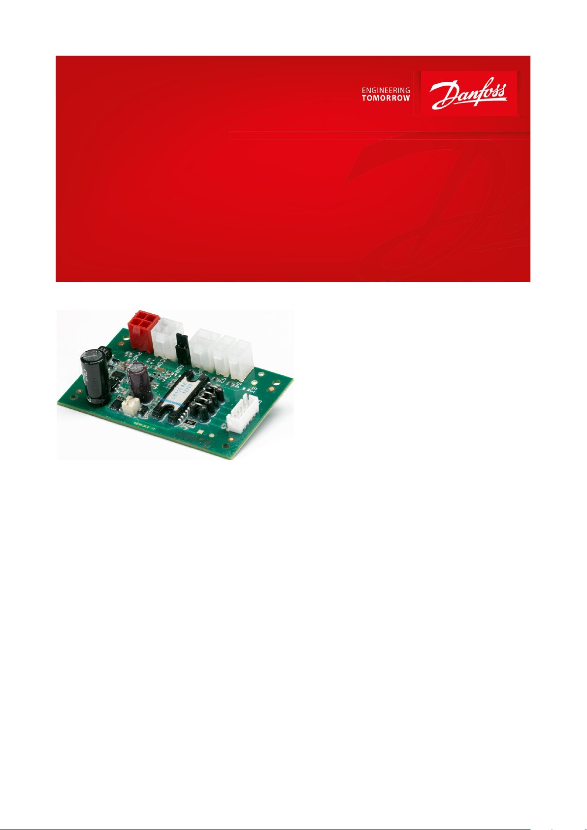
Superheat controller
Type EIM 336
For stepper motor valves
The EIM 336 is a superheat controller that can
be used to control the opening degree of a
valve based on the superheat of the evaporator.
This is applicable in applications such as air
conditioning, heat pumps and refrigeration.
An alternative option is to use the controller in
manual mode via modbus communication and
use it as a valve driver by setting the valve
opening degree manually.
Benets
• The evaporator is charged optimally even
when there are large variations in load and
suction pressure.
• The superheat control can save energy by
ensuring optimum utilization of the
evaporator.
• The superheat is controlled to the lowest
stable value.
• It controls EEV in microsteps providing a
smooth superheat curve and less noise.
Features
• Minimum Stable Superheat search regulation
(MSS).
• Maximum Operating Pressure function
(MOP).
• Defrost.
• Compressor protection functions.
• Evaporator temperature (Te) control for dehumidifying.
• Valve driver via Modbus Communication.
• Loss Of Charge indication (LOC).
AI219486429676en-000301
Page 2
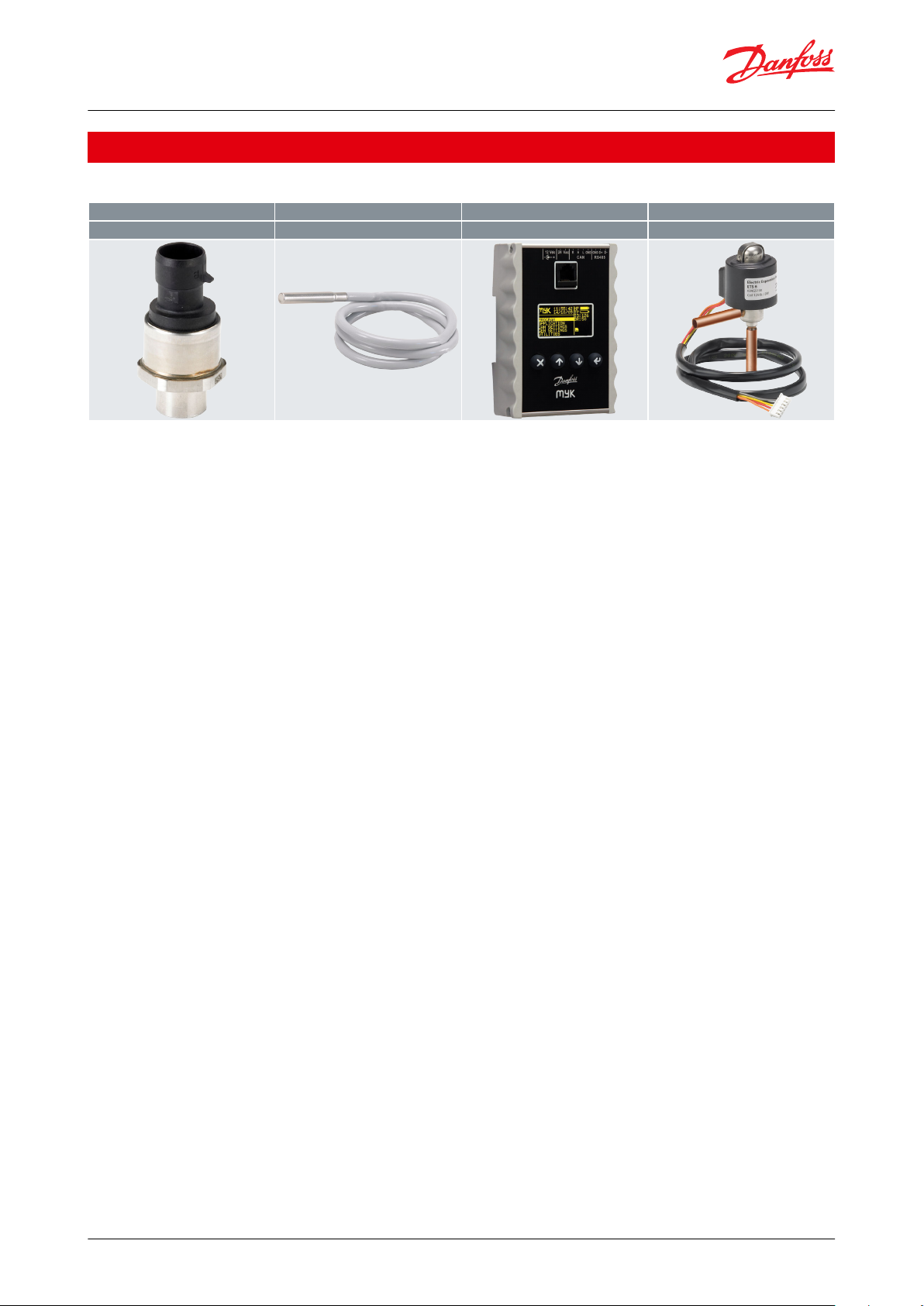
Pressure transducer
Temperature sensor
Programming key / display
Electric Expansion valve
DST P110, AKS 32R, NSK BExx
AKS 21, AKS 11
MYK - EIM interfacer
ETS6
Superheat controller, Type EIM 336
1 Portfolio overview
Table 1: Related products
© Danfoss | Climate Solutions | 2021.02 AI219486429676en-000301 | 2
Page 3

Superheat controller, Type EIM 336
2 Functions
2.1 Acronyms and abbreviations
LOC Loss of charge indication
SH Superheat
MOP Maximum operating pressure
MSS Minimum stable superheat
Te Saturated suction temperature
Pe (Po) Evaporator pressure
S2 Evaporator refrigerant outlet temperature
S4 Evaporator medium outlet temperature
OD Opening degree
PNU Parameter number - is equivalent to the modbus register no. (modbus adress + 1)
2.2 Functions
Minimum Stable Superheat (MSS)
The controller will search for the minimum stable superheat between an upper and lower boundary set by the user.
If the superheat has been stable for a period of 6 minutes, the superheat reference is decreased. If the superheat
becomes unstable, the reference is raised again. This process continues as long as the superheat is within the
bounds set by the user. The purpose of this is to search for the lowest possible superheat that can be obtained while
still maintaining a stable system. The superheat reference can also be xed, in which case this function is disabled.
Maximum Operating Pressure (MOP)
In order to reduce the strain on the compressor, a maximum operating pressure can be set. If the pressure comes
above this limit the controller will control the valve to provide a lower pressure instead of a low superheat. The limit
for this function is usually a xed pressure, but it is possible to oset the limit temporarily.
Evaporator temperature (Te) control for de-humidifying
A function is provided to control on the evaporator temperature instead of the superheat. This can be used to dehumidify the air owing through the evaporator. By lowering the evaporators surface temperature, the water vapor
in the air is condensed.
Superheat close
When the superheat is below a set minimum value, the valve will close faster in order to protect the compressor
from the risk of getting liquid in the suction line.
Manual control
The valve can be controlled manually by setting the desired opening degree via modbus.
Start/stop of regulation
The start or stop of the regulation can be controlled by setting the software main switch, which is accessible via
modbus. It is however also possible to use a digital input from an external Regulation control On / O switch.
Loss Of Charge indication (LOC)
A function is provided to indicate loss of refrigerant charge. This is only indicated by setting an alarm ag which can
be accessed via modbus. No special action is performed by the controller.
External sensor values
The EIM 336 has sensor inputs for the suction pressure and evaporator temperature (S2). It is however possible to
substitute these sensor inputs by sending external sensor values via modbus. These external values need to be
updated frequently.
Forced opening during startup
In some applications it is necessary to open the valve quickly when the compressor turns on, to prevent too low
suction pressure. This is ensured by setting a xed opening degree and a startup time for the controller. Note that
this will give a xed opening degree for the duration of the start time, regardless of the superheat value.
© Danfoss | Climate Solutions | 2021.02 AI219486429676en-000301 | 3
Page 4

Superheat controller, Type EIM 336
Forced opening during o
In some applications the valve must remain open when the controller is o. This can be done by setting a xed
opening degree. When normal control is switched o with the main switch, the valve will keep this opening degree.
Defrost handling
The controller does not itself handle defrost of the evaporator. It is however possible to enter a special defrost
sequence, which will overrule the normal control of the valve.
Standalone function
The EIM 336 is designed to operate in conjunction with a system master controller, which will control the EIM 336
via modbus. It is however possible to use it in a standalone mode with no external control, except a digital input
from the Regulation control On / O switch. In this conguration some of the other functions will not be available.
© Danfoss | Climate Solutions | 2021.02 AI219486429676en-000301 | 4
Page 5
Danfoss
80G39.12
AKS 11
Evaporator
EIM 336
AKS32R
ETS 6
Superheat controller, Type EIM 336
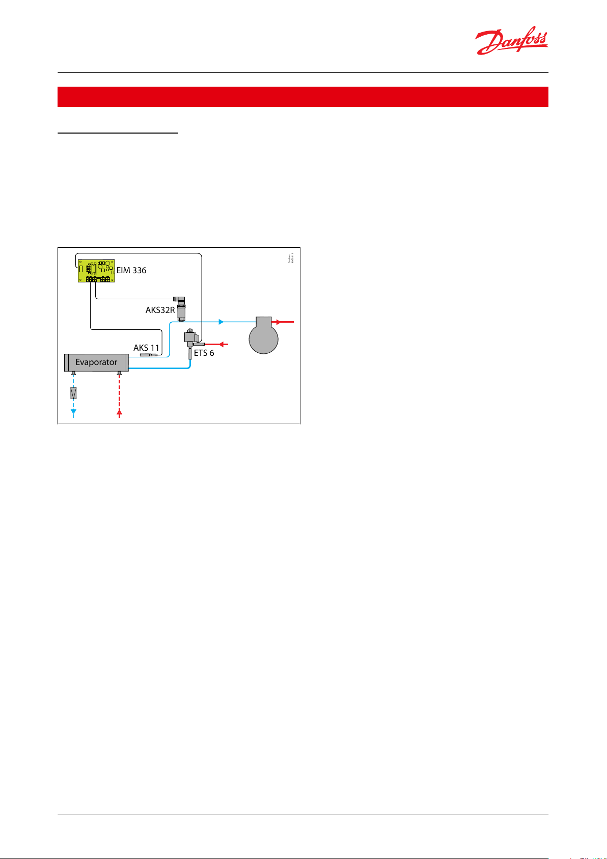
3 Applications
3.1 Regulation control
The evaporator superheat is controlled by one pressure sensor Pe (evaporator pressure) and one temperature
sensor S2 (refrigerant temperature). Alternatively the pressure and temperature signals can be received as data via
modbus. This can be useful if the pressure and temperature sensors are mounted on a separate controller.
Fitting the S4 (evaporator medium outlet temperature) is optional and has no eect on regulation, it is a readout
value only. S4 can however be setup as a Regulation control On / O switch instead to provide an external ON/OFF
function for the controller.
Figure 1: Regulation control
© Danfoss | Climate Solutions | 2021.02 AI219486429676en-000301 | 5
Page 6
Danfoss
80G164.10
PWR
PO
EEV
S4
S2
COM
ADR
1
3
2
+
-
V
P
T
C
E
VPT
C
E
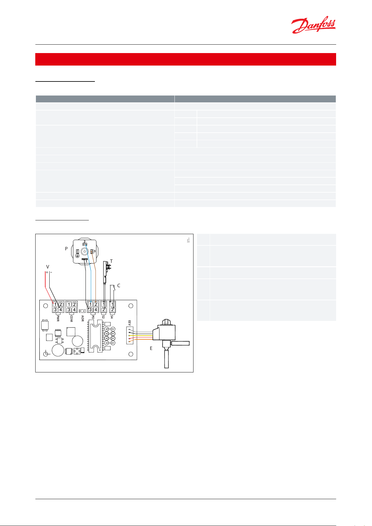
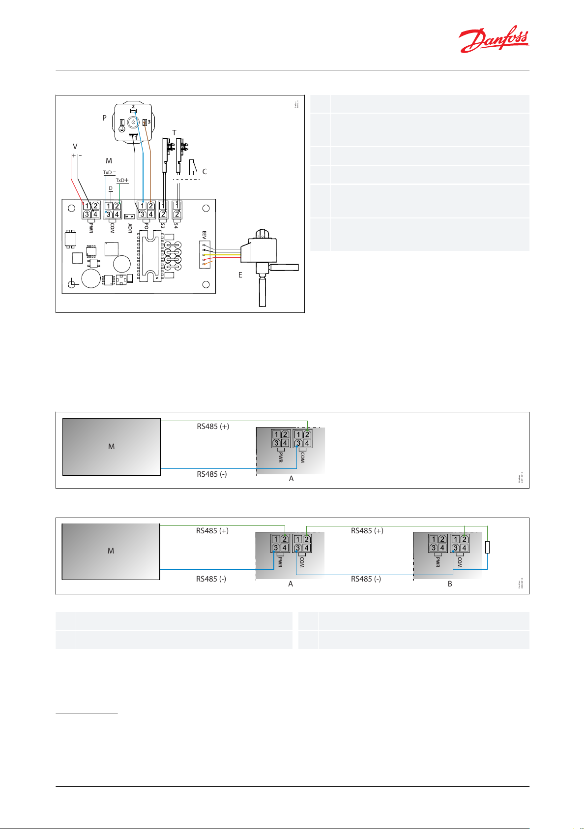
Power Supply 24 V AC or DC
Pressure transmitter Ratiometric 0.5 – 4.5 V i.e.
AKS 32R
Temperature sensors PT 1000 i.e. AKS 11
Regulation control On/O switch (Enable
parameter HW Main Switch to 1)
Electric expansion valve ETS 6 with JST-XHP 5
connector
Features
Description
Supply voltage
24 V AC / DC (± 15%), 50 / 60 HZ, 15 VA / 8 Watt, Class II isolation
Power consumption
Idle
Max. 150 mA @ 24 V DC
Operating
Max. 150 mA @ 24 V DC
Input signals
For the EMC compliance, sensor cable length must be < 3m / 118 in.
For longer sensor cable, a ferrite bead should be used.
Po
AKS 32R (or similar ratiometric pressure transmitter)
S2
PT1000 (measuring range -60 – +120°C / -76 – 248 °F)
S4
PT1000 or digital input from external contact.
EEV driver
Max. current 150 mA RMS
EEV
Uni- or bipolar coil with JST XHP-5 connector
Data communication
RS485 – Modbus RTU (Not terminated internally)
Environment
Storage: -34 °C to 71 °C / -30 °F to 160 °F
Operating: -25 °C to 60 °C / -13 °F to 140 °F
Humidity: <95% RH, non condensing
Dimensions
25 × 50 × 80 mm / 0.98 × 1.97 × 3.15 inch
Operation
Stand alone or via Modbus data communication
Superheat controller, Type EIM 336
4 Product specication
4.1 Technical data
Table 2: Technical data
4.2 Connections
Figure 2: Stand alone conguration
© Danfoss | Climate Solutions | 2021.02 AI219486429676en-000301 | 6
Page 7
Danfoss
80G15.11
PWR
POS4S2
COM
ADR
+
-
TxD+
TxD
-
D
EEV
1
3
2
V
M
P
T
C
E
VPM
T
C
E
Power Supply 24 V AC or DC
Pressure transmitter Ratiometric 0.5 – 4.5 V i.e.
AKS 32R
Modbus to master controller
Temperature sensors PT 1000 i.e. AKS 11
Regulation control On/O switch (Enable
parameter HW Main Switch to 1)
Electric expansion valve ETS 6 with JST-XHP 5
connector
MAB
R
Danfoss
80G166.10
PWR
COM
M
RS485 (-)
A
RS485 (+)
M
A B
RS485 (-)
RS485 (+)
RS485 (-)
RS485 (+)
Danfoss
80G165.10
PWR
COM
PWR
COM
Master controller
EIM slave 1
EIM slave 2
120 Ohm min. 0.25 Watt
Superheat controller, Type EIM 336
Figure 3: System conguration (default factory settings)
IMPORTANT:
• The supply voltage is not galvanically separated from the input and output signals, hence it is not recommended
to use shared power supply.
• No voltage should be supplied externally, if S4 terminal is setup as a Regulation on/o switch.
• Do not reverse the polarity of the power connection cables or Modbus signal cable else it could damage the
terminals.
Figure 4: Modbus one to one connection
Figure 5: Modbus in Daisy Chain
• If two EIMs are connected remember to remove the addressing jumper on one of the EIMs.
• Modbus transmission lines usually require termination resistors, especially for longer cable lengths.
4.3 Settings
NOTE:
4.3.1 Setting controller in Superheat control mode
NOTE:
Make sure that r12 = 0 (OFF) and change the settings. The setting will depends on the system requirement.
© Danfoss | Climate Solutions | 2021.02 AI219486429676en-000301 | 7
Page 8

Features
Description
Enabling Regulation control ON/O switch
(optional)
HwMainSwitch = 1 (default is 0, i.e S4 sensor)
For standalone conguration it is recommended to enable Regulation control ON/O switch in order to control start/
stop regulation when needed, otherwise the controller will start regulating when controller is powered up.
Select Refrigerant
o30 = 1 - 42 (default value is 20 i.e R407C)
Select valve setting(optional)
n37 = 384 x 10 micro step (3840 micro steps = 480 half steps).
n38 = Max. steps/sec, default value is 31 half steps
For other valve type than Danfoss check the technical spec. of the valve.
Dene pressure sensor range in bar absolute
(x10)
o20 = Min. Transducer pressure
o21 = Max. Transducer pressure
Dene min/max superheat
n10 = min. superheat reference
n09 = max. superheat reference
For xed superheat dene n09 = n10
Dene MOP (optional)
n11 = maximum operating pressure (default is 12.5 bar absolute, max. 200 = MOP o)
Set force opening of the valve ( optional)
Start OD% (n17 )
StartUp time (n15)
To start the superheat control
Set r12= ON
Features
Description
Select Application mode
o18 (PNU 2075 )= 1 i.e Manual control
Select valve setting(optional)
n37 = 384 x 10 micro step (3840 micro steps = 480 half steps).
n38 = Max steps/sec, default value is 31 half steps
for other valve type than Danfoss check the technical spec of the valve
Select Manual opening degree
o45 Manual OD % (PNU 2064)
0 = fully closed, 100 = fully open.
Symbolic name
PNU
Description
o30 Refrigerant
2551
1 = R12
2 = R22
3 = R134a
4 = R502
5 = R717
6 = R13
7 = R13b1
8 = R23
9 = R500
10 = R503
11 = R114
12 = R142b
13 = User dened
14 = R32
15 = R227
16 = R401A
17 = R507
18 = R402A
19 = R404A
20 = R407C
21 = R407A
22 = R407B
23 = R410A
24 = R170
25 = R290
26 = R600
27 = R600a
28 = R744
29 = R1270
30 = R417A
31 = R422A
32 = R413A
33 = R422D
34 = R427A
35 = R438A
36 = Opteon XP10
37 = R407F
38 = R1234ze
39 = R1234yf
40 = R448A
41 = R449A
42 = R452A
Superheat controller, Type EIM 336
Table 3: Setting controller in Superheat control mode.
4.3.2 Setting controller in valve driver mode using Modbus signal
NOTE:
Make sure that r12 = 0 (OFF) and change the settings so they t to their application.
Table 4: Setting controller in valve driver mode using Modbus signal
By changing parameter o45 Manual OD, the valve will move accordingly regardless of r12 parameter value.
4.3.3 Selecting a refrigerant
The controller needs to know which refrigerant is used in order to accurately control the superheat. This can be
selected by setting the “o30 Refrigerant” to the desired refrigerant as dened in the list below.
If no refrigerant is selected (“o30 Refrigerant” is set to 0 meaning the refrigerant is undened), the “No Rfg. Sel.”
alarm is set and the controller will not start regulating.
Refrigerant setting
Before refrigeration can be started , the refrigerant has to be dened. You can select the following refrigerant.
Table 5: Related parameters
WARNING:
Wrong selection of refrigerant may cause damage to the compressor.
4.3.4 Connecting and setting up a valve
The EIM 336 controller is designed to be used with Danfoss ETS 6 valves with a maximum of 480 pulses from fully
closed to fully open. This setting should not be changed.
© Danfoss | Climate Solutions | 2021.02 AI219486429676en-000301 | 8
Page 9

Symbolic name
PNU
Description
n38 Max. Steps Sec.
3033
Steps per second
n39 Start BckLsh
3034
Backlash, is the additional amount of steps, in percent, to close at startup and when the valve opening degree is less than 1%.
n40 Backlash
3035
Start Backlash is the amount of steps to compensate for spindle play.
Symbolic name
PNU
Description
o20 MinTransPres
2034
Minimum transducer pressure (in bar absolute x 10). Example: 0 bar absolute is entered as 0
o21 MaxTransPres
2033
Maximum transducer pressure (in bar absolute x 10). Example: 13 bar absolute is entered as 130
Superheat controller, Type EIM 336
The speed of the valve can be changed by increasing or decreasing the number of pulses per second, “n38 Max
StepsSec”. A larger value will make the valve open or close faster. Note that the torque of a stepper motor decreases
as the speed increases. Too high speeds should therefore be avoided. For the ETS 6 valve, the recommended speed
setting is 31 pulses per second.
When the controller is powered, the valve will rst be closed fully so that the controller starts from a known opening
degree (0%). In order to make sure that it is fully closed, the valve will be closed 100% plus an additional
contribution known as start backlash. The start backlash takes into account that the stepper motor may loose some
steps due to too low torque or mechanical slippage in the gears etc. The start backlash is the amount of extra steps
in percent to close once the valve is closed (less than 1%). If the valve is opening and reaches its destination, it will
move additional steps in the opening direction, then move the same amount of steps in the closing direction. This is
called backlash and is the amount of steps to add to compensate for spindle play.
Table 6: Related parameters
4.3.5 Connecting and setting up a pressure sensor
The pressure sensor input is setup by default to accept an AKS32R pressure transducer. If another sensor is to be
used, it is important to note that it needs to be a 0.5 - 4.5 V d.c. ratiometric type (10% - 90% of supply voltage).
The default range for the sensor is 0 to 16 bar absolute. This can be changed by setting the minimum transducer
pressure, “o20 MinTransPres” and the maximum transducer pressure, “o21 MaxTransPres” to the new values. The
values must be entered in bar absolute so a sensor with a range of -1 to 12 bar gauge, needs to bedened as 0 to 13
bar absolute.
Table 7: Related parameters
NOTE:
Both Danfoss AKS 32R and Danfoss Saginomiya Pressure transmitter NSK-BExxx follows the relative (gauge)
pressure, therefore same rules applies as explained above in converting and dening it in bar absolute in EIM
controller.
Mounting pressure transmitter
Installation of the pressure transmitter is less critical, but mounting of pressure transmitter should be closer to the
temperature sensor, right after the evaporator and with its head in upright position.
Power supply:
• Grounding of secondary (output) of transformer is not recommended.
• Do not reverse the polarity of the power connection cables and avoid ground loops (i.e. avoid connecting one
eld device to several controllers as this may result in short circuits and can damage your device).
• Use individual transformers for EIM 336 controller to avoid possible interference or grounding problems in the
power supply.
WARNING:
• Separate the sensor and digital input cables as much as possible (at least 3 cm) from the power cables to the loads
to avoid possible electromagnetic disturbance.
• Never lay power cables and probe cables in the same conduits (including those in the electrical panels).
© Danfoss | Climate Solutions | 2021.02 AI219486429676en-000301 | 9
Page 10

1
Danfoss
60G496.10
1
Conductive paste
Danfoss
84N365.10
OD
OD
OD
1
/2-5/8in.
12 - 16 mm
3
/4-7/8in.
12 - 16 mm
1 - 13/8in.
12 - 16 mm
OD
Danfoss
80G167.10
1 2
12Evaporator
sensor mounted close to the evaporator
Superheat controller, Type EIM 336
Mounting temperature sensor
Figure 6:
IMPORTANT:
Figure 7:
Figure 8:
• Mount sensor on a clean surface without any paints.
• Remember to put on heat conducting paste and insulate the sensor.
• Sensor mounting max. 5 cm from the outlet of the evaporator to get the precise measurements.
Figure 9: Mounting sensor
4.3.6 Using external sensor values
In some applications, the suction pressure and/or the refrigerant temperature on the evaporator outlet, is measured
by a system controller. This is often the case if the suction pressure is used to trigger low temperature/pressure
alarms by the systems main controller. In these cases the sensors can be omitted from the EIM 336, and the sensor
values can be received via modbus instead. This requires that the systems main controller continuously transmits
these values to the EIM 336. If no new sensor value is received within 5 seconds of the last transmission, the sensor
will revert to using the physical sensors.
The suction gas temperature S2 and the evaporator pressure Pe can be set by writing to the registers “ext S2 Temp”
and “ext EvapPress P0” respectively.
NOTE:
The external evaporator pressure is received in millibar so 8.4 bar absolute must be sent as 8400. It is possible to set
the S4 temperature as an external sensor value also, but since this sensor is not used in the superheat regulation,
this has little practical use.
© Danfoss | Climate Solutions | 2021.02 AI219486429676en-000301 | 10
Page 11
Danfoss
80G11.10
18
16
14
12
10
8
6
4
2
0
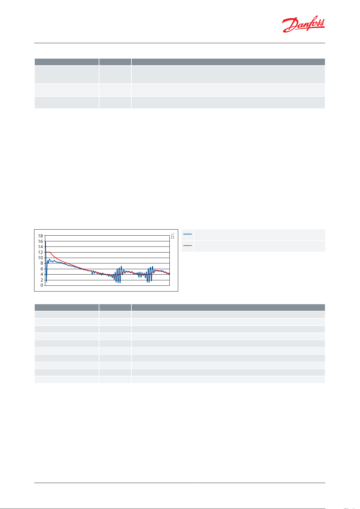
SH
SH ref
Symbolic name
PNU
Description
ext EvapPress P0
2643
External evaporator pressure. This value can be used instead of a sensor.
This register must be written at least every 5 second, otherwise the sensor value will be used.
The entered value is in millibar
ext S2 temp
2644
External S2. This value can be used instead of a sensor.
This register must be written at least every 5 second, otherwise the sensor value will be used.
ext S4 air temp.
2646
External S4. This value can be used instead of a sensor. This register must be written at least every 5 second,
otherwise the sensor value will be used.
Symbolic name
PNU
Description
n09 Max. SH
3015
Maximum superheat reference setting.
n10 Min. SH
3021
Minimum superheat reference setting.
n20 Kp T0
3025
Pressure feedback gain.
n22 SH close
3027
Superheat close level. If the superheat goes below this value, the valve will close faster.
--- Tn SH
3103
Integration time for superheat control
--- Alpha
3111
Design time constant. A large alpha means a slow response, a small alpha mean a fast response.
--- Max. SH shdw
64301
Copy of 3015. If it is required to write n09 frequently, this should be used instead.
--- Min. SH shdw
64302
Copy of 3021. If it is required to write n10 frequently, this should be used instead.
--- Tn SH shdw
64303
Copy of 3103. If it is required to write TnSH frequently, this should be used instead.
--- Alpha shdw
64304
Copy of 3111. If it is required to write alpha frequently, this should be used instead.
Superheat controller, Type EIM 336
Table 8: Related parameters
4.3.7 Conguring the superheat control
The superheat control algorithm will attempt to regulate the superheat down to the lowest stable value between
the minimum superheat setting, “n10 Min SH” and the maximum superheat setting, “n09 Max SH”. If a xed
superheat reference is desired instead, the “n10 Min SH” and “n09 Max SH” can both be set to the desired reference
value. This will disable the minimum stable superheat search algorithm and the controller will instead regulate the
superheat according to this reference.
The time constant for the superheat control can be changed by setting “Tn SH”.
The alpha value is the design time constant and should be in reasonable proximity to the time constant of the
evaporator. A large alpha value means a slow reaction, a small alpha value means a fast reaction.
If the superheat drops below “n22 SH close”, the controller will close the valve faster to avoid the risk of liquid in the
compressors suction line.
Figure 10:
Table 9: Related parameters
NOTE:
Main Switch r12 should be ON to start the regulation. This can also be accomplished with the external Regulation
control ON/O switch. See Interactions for details.
4.3.8 System conguration
The EIM 336 controller has a default conguration to be operated via modbus and to rely on a constant connection
to the master controller of the system it is located within. In this conguration the master controller reads the
readout registers from the EIM 336 and uses the parameters to change the control behaviour of the EIM 336 (see
Parameter list).
The following control modes are available:
© Danfoss | Climate Solutions | 2021.02 AI219486429676en-000301 | 11
Page 12

ETS 6
Evaporator
S4
S2 P
EIM 336
Modbus
Danfoss
80G41.11
Symbolic name
PNU
Description
o18 Manual ctrl.
2075
0 = Superheat control,
1 = Manual control
o45 Manual OD%
2064
Manual opening degree in percent.
0 = fully closed,
100 = fully open.
Used when the o18 Manual Control is set to 1.
Superheat controller, Type EIM 336
• Minimum Stable Superheat search (MSS) is the default control mode
• Manual control
• Defrost
• Maximum Operating Pressure control (MOP)
• Te control (De-humidifying).
Controlling manually via modbus
When setting the manual control register “o18 Manual ctrl.” to 1, the controller will be in manual control. During this
mode the opening degree is controlled by setting the “Manual OD%”. The manual control mode does not depend
on the “r12 Main Switch”, and will set the opening degree regardless of its setting. Setting “o18 Manual ctrl.” to 0
again, the controller will assume normal control, and will open or close from the current opening degree.
Figure 11: Controlling manually via modbus
NOTE:
On using system conguration , it is necessary to read the "Ctrl Stats" register 3100 continuosly, failure to do so will
start the MSS regulation automatically irrespective to the dierent status of the regulation On / O switch. Refer
Appendix 1 for detail.
Table 10: Related parameters
Standalone conguration (no Modbus communication)
The EIM 336 can be set in a standalone conguration by setting the modbus register i.e “HWMainSwitch” to 1. This
will setup the S4 input to be used as a Regulation On / O switch. Note that only external control of the EIM 336 in
this conguration is through the Regulation On / O switch.
The following control modes are available:
• Minimum Stable Superheat search (MSS) is the default control mode
• Maximum Operating Pressure control (MOP), but the Di MOP option is not available
The following control modes are not available:
• Manual control
• Defrost
• Te control (De-humidifying)
© Danfoss | Climate Solutions | 2021.02 AI219486429676en-000301 | 12
Page 13

EIM 336
S4 = 1
Danfoss
80G40.11
ETS 6
Evaporator
S2 P
Symbolic name
PNU
Description
--- HWMainSwitch
64100
0 = no external main switch
1 = regulation control On / O switch
Superheat controller, Type EIM 336
Figure 12: Standalone conguration (no modbus communication)
NOTE:
That the only external control of the EIM 336 in this conguration is through the Regulation control On / O switch.
It is not possible to manually control the opening degree or change settings, and the defrost and Te control modes
are not available.
Table 11: Related parameters
4.3.9 MODBUS Communication
Setting up modbus parameters
The modbus baud rate, “Modbus Baud”, can be set to three dierent baud rates. The modbus parity “ModbusParity”
can be set to either no parity, odd parity or even parity. The modbus stop bit can be set to either 1 or 2 stop bits. The
default settings are 19200 baud, even parity and 1 stop bit.
A jumper KM7 has been added to the EIM 336, for selecting between two predened addresses. This is useful for
applications such as reversible air conditioning/heat pump systems with both an indoor and an outdoor unit. In this
way the address can be changed without the need to recongure the controllers settings. The primary unit address
“o03 Unit addr.” is used when the jumper is mounted. The secondary unit address “Unit Addr. 2” is used when the
jumper is not mounted. The default primary address is 165, the default secondary address is 164.
NOTE:
Changes to these parameters will become active immediately. This means that a modbus tool or controller that
changes these settings will loose connection to the EIM 336 and will need to reestablish connection using the new
settings.
The EIM 336 “read holding registers” function (0x03) is limited to a maximum of 20 consecutive registers per read
request. If a modbus tool or a controller is used to read parameters over modbus, it needs to take this into account.
During the communication the transmitted Modbus requests are checked for CRC errrors. If the CRC is not correct,
the request is discarded and the EIM 336 waits for a new request. In this case no exception response is issued.
Loss of communication
The EIM will expect that a master controller reads the status register ( PNU 3100) at least every 30 seconds or more
often. If this does not happen the controller will switch to stand-alone control mode. Without communication it will
assume it is ON, and it will disregard the current status of the SW main switch (PNU 117). Under normal conditions it
will control the superheat by adjusting the opening degree based on the sensor inputs.
NOTE:
The 30 second timer is reset every time the status register is read by the master controller. if communication is loss
when the controller was in manual control, then it will remain in manual control, and keep its current opening
degree regardless of superheat.
© Danfoss | Climate Solutions | 2021.02 AI219486429676en-000301 | 13
Page 14
Danfoss
84N404.10
RS485 +
RS485 –
N
G
NGNot in use
Gnd
Symbolic name
PNU
Description
o03 Unit addr.
2008
Primary unit address is used when jumper KM7 is mounted
--- Unit Addr. 2
2009
Secondary unit address is used when the jumper KM7 is not mounted
--- Modbus Baud
50060
Communication setting baud rate, 0 =9600 , 1 = 19200, 2 = 38400
--- ModbusParity
50061
Communication setting parity, 0 = no parity, 1 = odd parity, 2 = even
--- ModbusStopB
50062
Communication setting stop bit, 1 = 1 stop bit, 2 = 2 stop bit
Superheat controller, Type EIM 336
Table 12: Related parameters
For detailed explanation and examples, please refer to manual ‘ EKD EIM Data communication Modbus RS485 RTU’
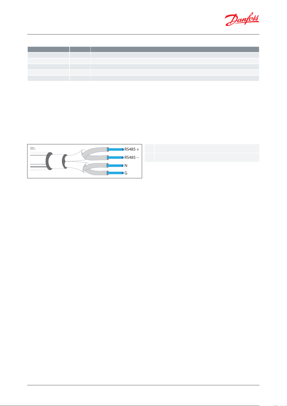
Connecting Modbus
• For the modbus cable, it is best to use 24AWG shielded twisted-pair cable with a shunt capacitance of 16 pF/ft and
100Ω impedance.
• The max. permissible number of devices simultaneously connected to RS485 output is 32. The RS485 cable is of
impedance 120 Ω with maximum length of 1000 m.
• Terminal resistors 120 Ω for terminal devices are recommended for length > 1 m.
Figure 13: Connecting Modbus
Detail explanation on Modbus installation and software parameter setting can be found in User guide: DATA
COMMUNICATION MODBUS RS 485 RTU
WARNING:
• Accidental damage, poor installation, or site conditions, can give rise to malfunctions of the control system, and
ultimately lead to a plant breakdown.
• Every possible safeguard is incorporated into our products to prevent this. However, a wrong installation, for
example, could still present problems. Electronic controls are no substitute for normal, good engineering practice.
• Danfoss will not be responsible for any goods, or plant components, damaged as a result of the above defects. It is
the installer’s responsibility to check the installation thoroughly, and to t the necessary safety devices.
• Particular attention is drawn to the need for a “force closing” signal to controllers in the event of compressor
stoppage, and to the requirement for suction line accumulators.
4.3.10 Using the MOP
In order to reduce the current to the compressor it is possible to control the maximum operating pressure of the
evaporator. If the evaporator pressure exceeds the “MOP” limit, the valve opening degree is controlled by the MOP
function which will keep the pressure below the “MOP” limit. This function takes precedence over the superheat
control, so during MOP control the superheat is not controlled.
The MOP function can be disabled by setting the “MOP” to the maximum value (2000 equalling 200 bar absolute).
When the pressure reaches the set MOP point, an increase in OD is restricted. If the pressure reaches MOP + 0.5 Bar,
an increase in OD is prohibited, and instead the OD will start to decrease. If the pressure goes below the MOP point,
the controller will start to regulate the superheat normally.
The MOP controller consists of a separate PI control, which settings can be changed by setting “Kp MOP” and “Tn
MOP”. A large Kp will lead to a large change in opening degree even at small changes in the evaporator pressure,
but may lead to instability. A large Tn will lead to a slow reacting system, while a small Tn will lead to a fast reacting
system.
© Danfoss | Climate Solutions | 2021.02 AI219486429676en-000301 | 14
Page 15

MOP
b
t0
Danfoss
80G12.11
btbar
Time
MOP+0.5
MOP
VOD
P1 P2
Danfoss
84B3084.11
N C F
R
Pe
b
P1
P2
Pe
VODRNCF
At this pressure the OD increases slower and
slower.
At this pressure the OD no longer increases.
Beyond it the OD decreases.
pressure
Valve Opening Digree
Normal regulation
Normal OD
Controlled OD
Force closed OD
Symbolic name
PNU
Description
n11 MOP
3013
Maximum operation pressure. If Pe goes above this value, the controller will control on Pe, and not on superheat.
--- Kp MOP
3113
Kp proportional gain while in MOP control mode.
--- Tn MOP
3114
Tn integration time while in MOP control mode.
Superheat controller, Type EIM 336
Figure 14: MOP controlling
Figure 15: MOP disabling
Table 13: Related parameters
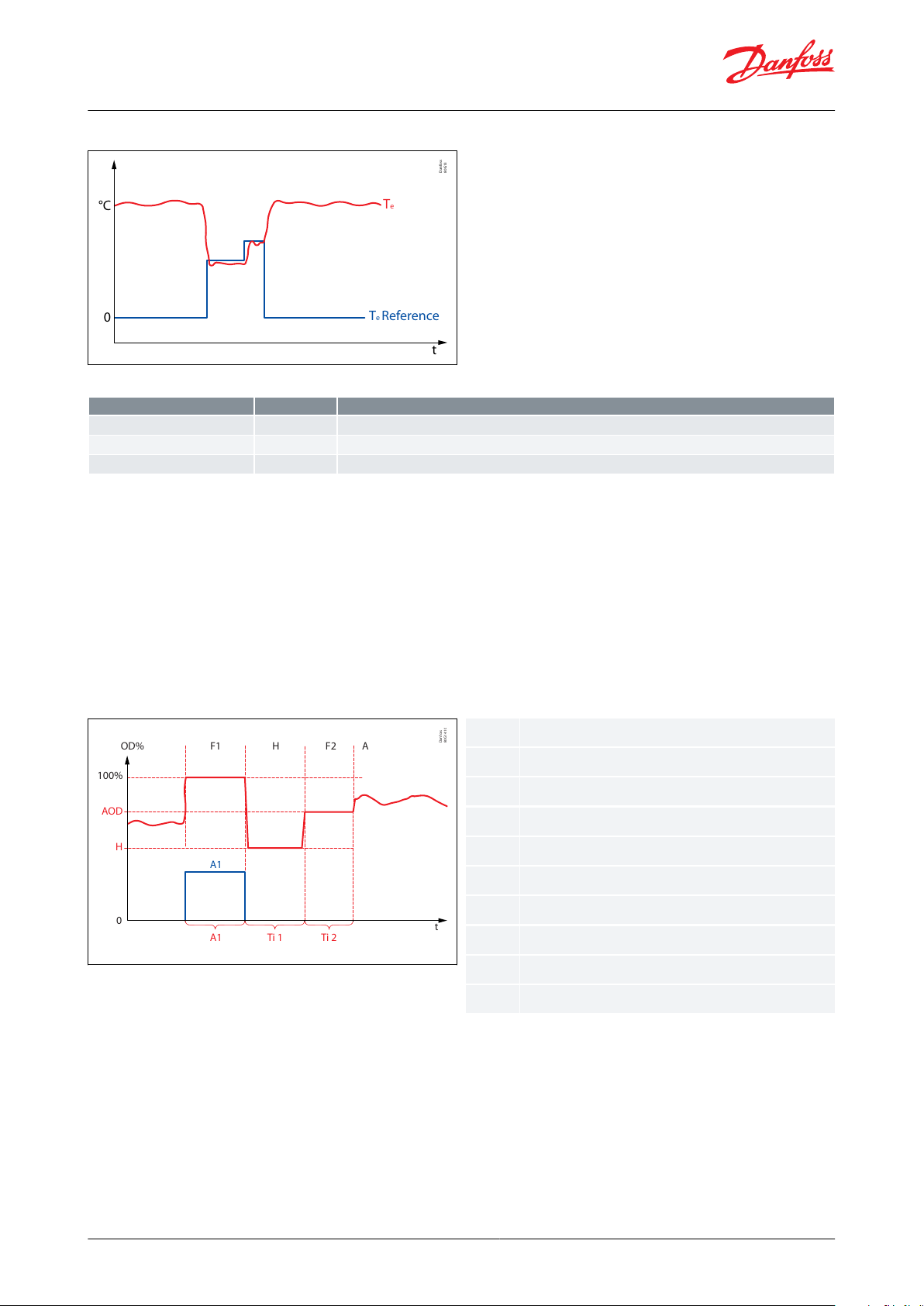
4.3.11 Using Te control
For applications with a need to de-humidify the evaporator, it is possible to control on the saturated evaporator
temperature instead of the normal control signal. If the “Te Reference” register is set to a value above 0, Te control is
activated. Te and the Te reference are used by the controller to calculate a new opening degree.
The Te control consists of a separate PI control, which settings can be changed by setting the gain, “Kp Te” and time
constant, “Tn Te”. A large Kp will lead to a large change in the output even at small changes in the evaporator
temperature, but may lead to instability. A large Tn will lead to a slow reacting system, while a small Tn will lead to a
fast reacting system.
The MOP function is still active during Te control and it will assume control, if the evaporator is above the “MOP”
limit. The SH close function is also active during Te control and will assume control if the SH is below the SH close
limit.
© Danfoss | Climate Solutions | 2021.02 AI219486429676en-000301 | 15
Page 16
AOD
H
Ti 2Ti 1A1
A1
A
t
F2HF1
OD%
100%
0
Danfoss
80G14.10
OD%
t
AODHF1F2AA1Ti 1
Ti 2
Opening degree in percentage
time
Avg. OD
Def Hold OD%
Fixed 100 OD%
Fixed Avg.OD%
Auto control
Defrost activate = 1
Def Hold time 1
Def Hold time 2
t
0
°C
Te Reference
Te
Danfoss
80G13
Symbolic name
PNU
Description
--- Kp T
e
3115
Kp proportional gain while in Te control mode
--- Tn T
e
3116
Tn integration time while in Te control mode
--- Te Reference
3117
Te reference while in Te control mode
Superheat controller, Type EIM 336
Figure 16: Using Te control
Table 14: Related parameters
4.3.12 Defrosting
A defrost sequence is initiated by setting the defrost activate register “Def Activate” to 1. As long as this register is
kept at 1, the valve opening degree is 100%. When “Def Activate” returns to 0, the valve opening degree is kept at
“Def Hold OD” for “Def Hold Ti 1” seconds. When this time expires, the valve opening degree is set to a calculated
average opening degree (PNU 50021) for “Def Hold Ti 2” seconds. When this time expires the controller resumes
normal operation.
The average opening degree is calculated as an average of the last hour while operating in injection state. Other
states such as manual control, defrosting or if the valve is fully closed are not included in the calculation of the
average.
Figure 17: Defrosting
NOTE:
• Defrost is not initiated by the EIM 336, but must be initiated by the master controller. In a standalone
conguration the defrost mode is not possible.
• If a more dynamic control of the opening degree during defrost is required, the user should disable the “Def Hold
Ti 2” by setting it to 0, and only use the “Def Hold Ti 1”. If frequent changes are to be made to the “Def Hold OD”,
the parameter “DefHold shdw” should be used instead. This parameter is an exact copy of the “Def Hold OD”
except that it is not placed in the Eeprom.
• If the communication is lost when the controller was in the process of defrosting, this process will continue. When
the entire sequence is completed it will go to superheat control. However, if the defrost activate signal was set
(50011), it will go to 100% opening. If it is never cleared, the sequence will stop, and it will stay fully open.
© Danfoss | Climate Solutions | 2021.02 AI219486429676en-000301 | 16
Page 17

Danfoss
84N400.10
FOD %
N
R%
VOD%
SOD %
S
t1 t
OD %
SOD%
FOD%
NR%Start OD%
Forced OD%
Normal Reg.
Reg. OD%
Symbolic name
PNU
Description
--- Def. Activate
50011
Defrost activating, 0 = no defrost, 1 = defrost active
--- Def. Hold OD
50008
Opening degree during Def Hold Ti 1
--- Def. HoldTi 1
50009
Defrost hold time 1
--- Def. HoldTi 2
50010
Defrost hold time 2
--- DefHold shdw
64305
Copy of 50008. If it is required to write Def Hold OD frequently, this should be used instead.
Symbolic name
PNU
Description
--- LOC Trig
50003
Trigger value for loss of charge
--- LOC Reset
50004
Reset value for loss of charge
--- LOC Timer
50005
Timer to trigger LOC alarm
--- LOC Alarm
50006
Loss of charge alarm ag, 0 = no alarm, 1 = LOC alarm
--- LOC SH Trig
50007
SH error trigger level for LOC alarm
--- LOC Tmr
3102
Loss Of Charge time readout displays the elapsed time since the alarm became active.
Superheat controller, Type EIM 336
Table 15: Related parameters
4.3.13 LOC detection
When a system loses refrigerant charge the controller will have diculties keeping the superheat low, even when
increasing the valve opening degree. Therefore, if both the valve opening degree and the superheat are high for a
long period of time, this could indicate that refrigerant charge was lost.
When the valve opening degree exceeds the trigger level "LOC Trig, and the superheat exceeds the superheat
trigger level "LOC SH Trig", a timer is started.
When the timer exceeds the user dened time “LOC Timer” the “LOC Alarm” is set. If the valve opening degree drops
below the user dened reset level “LOC Reset”, the timer and the alarm are reset.
The loss of charge alarm does not perform any actions, except setting the “LOC Alarm”.
Table 16: Related parameters
4.3.14 Finding the optimum settings
Details on the controller algorithm and settings
Problems with startup
Sometimes in one-to-one applications, the valve does not open suciently on startup, and troublesome low
pressure trips may occur.
The force opening of valve function has been implemented in the EIM 336 controller. After startup, this function will
provide a constant, set minimum opening degree during a set time period, regardless of the superheat value. The
setting parameters are called Start OD% (n17) and StartUp time (n15).
Figure 18: Forced opening of valve
© Danfoss | Climate Solutions | 2021.02 AI219486429676en-000301 | 17
Page 18

Superheat controller, Type EIM 336
Low Pressure Issue due to compressor cut in and cut out
One of the features of TEX valves is the external pressure equalization making a direct and fast responding pressure
connection between the compressor suction line and underside of the diaphragm in the valve. This enables the
valve to open-/ close momentarily with compressor capacity cut in and out.
The same function has been implemented into EIM 336, which is controlled by the parameter n20, KpTo. In this
function. kp factor related directly to the suction pressure (To) with direct eect on the requested signal to the ETS 6
valve .
The default value of KpTo is set to automatic (i.e -1). If the automatic tuning is not fullling the desired order,
Increasing the n20 setting to the xed value will contribute to an improvement. Too high n20 will produce high
uctuation in superheat regulation.
Fluctuating superheat
When the refrigerating system has been made to work steadily, the controller’s factory-set control parameters
should in most cases provide a stable and relatively fast regulating system. If the system however uctuates, this
may be due to the fact that too low superheat parameters have been selected or due set of regulation parameters
which are not optimal.
Usually, the following parameters can be tuned in order to reach fast, stable superheat in EIM controller.
1.
If adaptive superheat has been selected adjust n09 and n10 parameters. For some application using xed
superheat may increase the stability. This can be done by dening n09 and n010 to the xed value.
2.
To optimize the superheat regulation, most safe and direct way is to tune TnSH. For example, if a the control is
too slow, dene new Tn value to half (1/2 Tn), if it is still slow reduce it to another half (1/2 x 1/2 Tn= 1/4 Tn), If the
control start to oscillation, then return back to (~ 3/8 Tn) , alternatively read the time period and tune tn = 1.2 x
time period.
3.
Keep KpT0, Alpha as default, they work for most of the cases.
4.
Tune parameter for force opening of the valve at start up i.e. n15 (startup OD) and n17 (start up time). These
values depends on the system conditions.
NOTE:
Steps (1.) to (3.) are quite easy and safe to tune. For step (4.), caution should be taken, so as not to allow refrigerant
inside the compressor.
Too high uctuating pressure signal
1.
Tune parameter n20 KpT0 to lower value, if this is not working for the system disable by setting it to zero.
2.
If point 1 doesn’t seem to be working, then keep n20 KpT0 disable and increase para TSH (i.e Tan SH). Increase
TSH (default value) by 200 and check the oscillation. If the problem seems to persist, perform the same step up
to higher TSH value.
4.3.15 Alarms and clearing alarms
Several alarms are registered and made available on modbus. Most of these are automatically cleared when the
error is no longer present.
Sensor error : Temperature sensor error has a timeout of 10 minutes. This means that after the reason for a sensor
error has gone, the error will remain active for 10 minutes, and then it is cleared. for the pressure sensor, the timeout
is only 30 seconds.
There is an option to reset the errors externally by setting the 40075 (reset alarms) = 1.
© Danfoss | Climate Solutions | 2021.02 AI219486429676en-000301 | 18
Page 19

1.
2.
3.
Symbolic name
PNU
Description
--- Reset alarm
2046
1 = Clear alarm.
It is possible to clear alarms manually by setting Reset Alarms (40075). After setting this, the alarm is kept
active for
5 seconds before being cleared.
--- EKC Error
20001
Common error ag. EKC Error is SET if any other Error Alarm is ON.
EKC error is auto cleared after the last active alarm has been cleared.
--- S2 Error
20002
S2 sensor error. If the sensor error occurs, the valve OD will be set to 80% of the Avg. opening (PNU 50021) see Troubleshooting.
S2 alarm is auto cleared after 10 min after the alarm condition has been cleared.
--- S4 Error
-
S4 is not monitored
--- Pe inp.error
20005
Pressure transmitter out of range. If the sensor error occurs, the valve OD will be set to 80% of the Avg.
opening (PNU 50021)
- see Troubleshooting.
Pe alarm is auto cleared after 30 seconds.
--- No Rfg. Sel.
20006
Refrigerant not selected.
No Refrigerant selected alarm is auto cleared immediately after setting the refrigerant.
--- LOC Alarm
50006
Loss of charge alarm. No action will be performed except setting the alarm.
--- Ctrl Status
3100
Bit mappped status register, see also Control status
Symptom
Possible Cause
Remedy
Suction pressure too low
Pressure drop across the evaporator too high
-
Lack of subcooling ahead of expansion valve
Check refrigerant ahead of expansion valve. If the valve is placed much
higher than condenser outlet, check pressure dierence.
Evaporator superheat too high
Check superheat performance, the settings SH min and SH max.
Check valve capacity.
Check that the maximum number of steps of valve is same as
parameter n37.
Pressure drop across the expansion valve less than
valve is sized for
Check pressure drop across expansion valve. Replace with larger valve.
Expansion valve too small
Check refrigeration system capacity and compare with expansion valve
capacity. Replace with larger valve if necessary.
Expansion valve block with foreign material
Remove valve and examine the orice.
Evaporator wholly or partly iced up
De-ice evaporator
Liquid hammer in compressor
Superheat of expansion valve too low
Increase the values of SH close and SH min.
Superheat reference set too low
Increase the value of SH min
The S2 sensor not in good contact with the suction
line
Ensure that S2 sensor is secured on suction line. Insulate sensor.
S2 sensor error: PNU 20002
Bad connection or damaged S2 sensor
The controller will go to either the low or high boundary depending on
the error. The lowest value will be shown at a short circuit. The highest
value will be shown for a missing connection. Check the temperature
sensors.
AKS32R out of range: PNU 20005
The suction pressure is above the maximum limit or
below the minimum limit
The controller will go to either the low or high boundary depending on
the error. The highest value will be shown if the signal is above the maximum value. The lowest value will be shown if the signal is below the
minimum value or for a missing connection. Check the pressure range.
LED blinks during operation
No Modbus connection to master controller. (Controller entered autonomous control mode, and it will try
to control on its own if possible, or close if no sensor
signals are available).
Check Modbus connections between Master controller and the EIM
controller.
Chech the Modbus parameter setting in the controller.
Row text
Explanation
PNU
The Parameter Number in the EIM 336 controller. All parameters are addressed as holding register. The Modbus PDU address corresponds to PNU-1. If no translation table is used, this is the register number in modbus.
Min.
Minimum value
Def.
Factory default value
Max.
Maximum value
e2
Is the value stored in EEPROM
W
Is writing to the register possible
Superheat controller, Type EIM 336
Table 17: Related parameters
4.3.16 Troubleshooting
Table 18: Troubleshooting
4.3.17 Parameter list
Table 19: Parameter list legend
© Danfoss | Climate Solutions | 2021.02 AI219486429676en-000301 | 19
Page 20

Row text
Explanation
*10
The scaling of the parameter. All values are read/written as integers over modbus. Parameters need to be scaled, these are marked with a
checkmark. This means that 0.1 is sent as 1 over modbus, 1.0 is sent as 10 etc.
Symbolic name
The name of the parameter
Description
Short parameter description
Group
PNU
Parameter
Symbolic name
Min.
Max.
Default
Unitse2W
*10
Description
Regulation
Control
117
r12
Main switch
010--✓-
Start/stop of regulation. With this setting the regulation can be started and stopped. This can also be accomplished with the external hardware main switch.
See also Interactions
2075
o18
Manl control
010--✓-
0 = Superheat control, 1= Manual control
2064
o45
Manual OD
0
100 /
480
0
% /
step
-✓-
Manual opening degree for manual control .
Used when the o18 Manual Control is set to 1.
0%/0 step = fully closed,
100%/480 step = fully open.
% is chosen by default.
See PNU 64309 for changing to step.
3017
n15
Startup time
0
10000s✓✓-Time for startup state (in seconds)
3012
n17
Startup OD
0
1000%✓✓-Opening degree during startup state
64308
OOD
OD while OFF
0
1000%✓✓-Opening degree during
O state
Superheat controller, Type EIM 336
NOTE:
Some parameters have what is called a "cong lock". This means that they can only be changed when the main
switch of the EIM 336 is set to OFF (r12 = 0). This applies for instance to the type of refrigerant (o30). So if you want
to change the refrigerant, the main switch (r12) must rst be set to 0, then the refrigerant type (o30) can be
changed.
The following parameters require the main switch (r12) to be OFF:
• n37 Max steps
• n38 Max steps/sec
• o03 Unit address
• o30 Refrigerant
Please refer to the list below. It should be possible to change all other parameters while the unit is running
(regulation parameters etc.).
Shdw (x): Shdw values are stored in the volatile memory and will revert back to the previously stored value in its
main parameter if the power failure occurs. Altering the main parameter will automatically change the shdw value. If
frequent change in parameter required, it is recommended to use shdw parameter.
Table 20: Parameter list
© Danfoss | Climate Solutions | 2021.02 AI219486429676en-000301 | 20
Page 21

Group
PNU
Parameter
Symbolic name
Min.
Max.
Default
Unitse2W
*10
Description
Super Heat
Control
3015
n09
Max. superheat
25016K✓✓✓
Maximum superheat reference setting
3021
n10
Min. superheat
1504K✓✓✓
Minimum superheat reference setting
3025
n20
KpT0
-120-1-✓✓✓
Pressure feedback gain Automatic = -1, OFF = 0 , Fixed
= 1 and above
3027
n22
SH close
0160.5K✓✓✓
Superheat close level. If the superheat goes below this
value, the valve will close faster
3103
TSH
Tn SH
10
1800
600-✓✓-
Tn integration time for the superheat control. Lower
value give fast regulation response. Very low value
give the risk of unstable regulation.
3105
(1)
SHL
SH Low
3506K✓✓✓
Superheat low setting for non-linear control
3106
(1)
SHH
SH High
85016K✓✓✓
Superheat high setting for non-linear control
3107
(1)
GaH
Gain High
0.5501-✓✓✓
Expected gain at SH high for non-linear control
3108
(1)
GaL
Gain Low
0.15012.5-✓✓✓
Expected gain at SH low for non-linear control
3109
(1)
TaH
Tau High
10
60045-✓✓-Expected tau at SH high for non-linear control
3110
(1)
TaL
Tau Low
10
600
110-✓✓-
Expected tau at SH low for non-linear control
3111
Aph
Alpha
15
600
130-✓✓-
Design time constant. A large alpha means a slow response, a small alpha mean a fast response.
3120
CoS
Comp Speed
0
1000%-✓
✓
Compressor speed Tn=2x Tn if compressor speed is set
to 0% Tn= Tn if the compressor speed is set between
25 - 100% - ref. parameter 3103
64301
n09x
Max. superheat
shdw
25016K-✓✓
Copy of 3015. If it is required to write Max superheat
frequently, this should be used instead
64302
n10x
Min. superheat
shdw
1504K-✓✓
Copy of 3021. If it is required to write Min superheat
frequently, this should be used instead
64303
TSHx
Tn SH shdw
10
1800
600--✓-
Copy of 3103. If it is required to write TnSH frequently,
this should be used instead.
64304
Aphx
Alpha shdw
15
600
130--✓-
Copy of 3111. If it is required to write alpha frequently,
this should be used instead.
MOP
3013
n11
MOP
0
200
13.7
bar
(abs.)
✓✓✓
Maximum operation pressure. If Pe goes above this
value, the controller will control on Pe, and not on superheat
3113
KpM
Kp MOP
0.5100.5-✓✓✓
Kp proportional gain while in MOP control mode
3114
TnM
Tn Mop
30
600
180-✓✓-
Tn integration time while in MOP control mode
3121
DMO
Di MOP
-2000
bar
(abs.)
-✓✓
Dierential MOP. A remote oset that is added to the
MOP. Needs to be written every 5 seconds, else the o-
set is set to 0.
Defrost
50011
DeA
Def Activate
010--✓-
Defrost activating
50008
DHO
Def Hold OD
0
10030%✓✓-Defrost holding level
50009
DH1
Def Hold Ti 1
0
32000
120s✓✓-
Defrost holding timer 1
50010
DH2
Def Hold Ti 2
0
3200060s✓✓-Defrost holding timer 2
64305
DDO
Def hold OD
shdw
0
10030%✓✓
-
Copy of 50008. If it is required to write Def Hold OD
frequently, this should be used instead.
Te Control
3115
KpTe
Kp Te
0.5101-✓✓-
Kp proportional gain while in Te control mode
3116
TnT
Tn Te
30
60060-✓✓
-
Tn integration time while in Te control mode
3117
TeR
Te Reference
-200
2000°C-✓✓Te reference while in Te control mode
External sensors
2643
PEV
ext. EvapPress
P0
0
65535
0
milli
bar
-✓-
External evaporator pressure. This value can be used
instead of a sensor. This register must be written at
least every 5 seconds, otherwise the sensor value will
be used.
2644
TS2
ext. S2 temp
-200
2000°C-✓
✓
External S2. This value can be used instead of a sensor.
This register must be written at least every 5 seconds,
otherwise the sensor value will be used.
2646
TS4
ext. S4 Air temp
-200
2000°C-✓
✓
External S4. This value can be used instead of a sensor.
This register must be written at least every 5 seconds,
otherwise the sensor value will be used.
LOC
50003
LTR
LOC Trig
0
10095%✓✓-Trigger value for loss of charge
50004
LRe
LOC Reset
0
10085%✓✓-Reset value for loss of charge
50005
LTm
LOC Timer
0
7200
3600s✓✓-
Timer to trigger LOC alarm
50007
LST
LOC SH Trig
05020K✓✓✓
SH error trigger level for LOC alarm
Superheat controller, Type EIM 336
© Danfoss | Climate Solutions | 2021.02 AI219486429676en-000301 | 21
Page 22

Group
PNU
Parameter
Symbolic name
Min.
Max.
Default
Unitse2W
*10
Description
Modbus
20083Unit Addr
1
240
165-✓✓-
Primary unit address is used when jumper KM7 is
mounted
2009
UA2
Unit Addr 2
1
240
164-✓✓-
Secondary unit address is used when the jumper KM7
is not mounted
50060
MBa
MB Baud
021-✓✓-
Communication setting baud rate, 0 =9600 , 1 =
19200, 2 = 38400
50061
MPa
MB Parity
022-✓✓-
Communication setting parity, 0 = no parity, 1 = odd
parity, 2 = even
50062
MSB
MB StopB
121-✓✓-
Communication setting stop bit, 1 = 1 stop bit, 2 = 2
stop bit
64200-Modbus trans
031-✓✓-
1 = Enabling translation tables. If the translation table
is enabled, only registers some are accessible.
Valve
3032
n37
Max steps
100
1000
384-✓✓-
Maximum number of steps (384 x 10 microsteps = 480
half steps)
3033
n38
Max steps/sec
5
30031-✓✓-Steps per second
3034
n39
Start backlash
1
10010%✓✓
-
Backlash (steps) to close in percent at startup (power
on).
3035
n40
Backlash
0
10020%✓✓
-
Backlash (steps) for spindle play compensation. This is
active during normal control
3037
n42
Comp. dir.
121-✓✓-
Compensation direction
3051
n56
Motor current
0
300
150mA✓✓-
Motor current
Regfrigerant
2551
o30
Refrigerant
04223-✓✓-
1 = R12
2 = R22
3 = R134a
4 = R502
5 = R717
6 = R13
7 = R13b1
8 = R23
9 = R500
10 = R503
11 = R114
12 = R142b
13 = User def.
14 = R32
15 = R227
16 = R401A
17 = R507
18 = R402A
19 = R404A
20 = R407C
21 = R407A
22 = R407B
23 = R410A
24 = R170
25 = R290
26 = R600
27 = R600a
28 = R744
29 = R1270
30 = R417A
31 = R422A
32 = R413A
33 = R422D
34 = R427A
35 = R438A
36 = Opteon XP10
37 = R407F
38 = R1234ze
39 = R1234yf
40 = R448A
41 = R449A
42 = R452A
2548
RF1
Rfg. fac. A1
8000
12000
10428
-✓✓-Adiabatic constant A1
2549
RF2
Rfg. fac. A2
-4000
-1000
-2255-✓✓-
Adiabatic constant A2
2550
RF3
Rfg. fac. A3
1000
3000
2557-✓✓-
Adiabatic constant A3
Sensors
113
r09
Adjust S2
-1000K✓✓✓
S2 Oset adjustment to correct the sensor signal due
to long wires etc.
2033
o21
Max. transducer
pressure
1
200
16
bar
(abs.)
✓✓✓
Maximum transducer pressure (in bar absolute * 10)
2034
o20
Min. transducer
pressure
010
bar
(abs.)
✓✓✓
Minimum transducer pressure (in bar absolute * 10)
System
50020-Avg KT0 time
10
3600
180-✓✓-
Average time for KT0 used as ltervalue for the average opening degree calculation when calculating the
KT0
50021
-
Avg OD 3 hours
0
1000
100
per
mill
✓✓✓
Average OD, updated and saved every 3 hours. After
power up the last saved average OD is used as starting
average OD
50051
-
Sampling time
1101
sec.✓✓-Algorithm sampling time
64200
LBO
Limited list
010-✓✓-
Modbus translation table for limited list of sequential
registers
64100
HWM
HW main switch
010-✓✓-
1 = S4 input is HW Main Switch
64309
-
Manual OD as
steps
010-✓✓-
Enable the manual OD in o45 to be entered as halfsteps. Readouts are still in percent
Alarm
2046
RAL
Reset alarm
010--✓-
1 = clear alarm
20001-EKC Error
010----
Common error ag. EKC Error is SET if any other Error
Alarm is ON.
20002-S2 Error
010----
S2 sensor error. If the sensor error occurs, the valve OD
will be set to 80% of the Avg. opening (PNU 50021) see Troubleshooting.
20005-Pe inp.error
010----
AKS 32R out of range. If the sensor error occurs, the
valve OD will be set to 80% of the Avg. opening (PNU
50021) - see Troubleshooting.
20006-No Rfg. Sel.
010----
Refrigerant not selected
50006-LOC Alarm
010----
Loss of charge alarm. No action will be performed except setting the alarm.
Superheat controller, Type EIM 336
© Danfoss | Climate Solutions | 2021.02 AI219486429676en-000301 | 22
Page 23

Group
PNU
Parameter
Symbolic name
Min.
Max.
Default
Unitse2W
*10
Description
Readout
2531
u16
S4 air temp
-200
2000°C--
✓
S4 temperature in °C measured with PT 1000 sensor
connected to KM2
2535
u22
Superheat Ref
0
1000K--✓Current superheat reference
2536
u21
Superheat
0
1000K--✓Current superheat (S2 - evaporator temperature)
2537
u20
S2 Temp
-200
2000°C--
✓
S2 temperature in °C measured with a PT 1000 sensor
connected to KM1.
2542
u24
opening %
0
1000%---Actual opening degree
2543
u25
Evap Press Pe
-200
200
0
bar
(abs.)
--✓
Evaporator pressure measured with ratiometric pressure transmitter at KM6.
2544
u26
Evap Temp Te
-200
2000°C--
✓
Evaporator temperature (converted from evaporator
pressure)
3101-Closed valve T
0
20000----Closed valve timer
3102-LOC Tmr
0
20000----Loss Of Charge time
50033-Avg opening
0
1000%--
-
Average opening degree. If it has never run before it
will give the value of PNU 50021 at start up.
64306-SWVer shdw
xxx----
Copy of 2003. This displays the version number in a
non-EKC format. For example 123 means vers 1.23
Control status
3099-Control State
05-----
Current state of internal control state machine.
3100-Ctrl Status
0
20000-----Bit mappped status register. See also Control status.
Regulation Control
on/o
switch
r12
Result
SH control
Alarm handling
o
(open)o (0)
=oo
o
(open)
on (1)=ononon (closed)
o
(0)
=oo
on (closed)
on (1)=on
on
Regulation Control
on/o
switch
r12
Result
SH control
Alarm handling
o
(open)o (0)
=oo
o
(open)
on (1)=ooon (closed)
o
(0)
=onon
on (closed)
on (1)=on
on
Bit15Bit14Bit13Bit12Bit11Bit10Bit 9
Bit 8
Bit 7
Bit 6
Bit 5
Bit 4
Bit 3
Bit 2
Bit 1
Bit 0
Unused
MOP Active
Close Timer active
Sensor Errors
Control state
Variables / parameters
bit 10…15: unused
bit 9 : MOP
bit 9 : MOP active.
bit 8 : Close timer
bit 8: timer active
bit 4 …7: Sensor Errors
bit 4 : Te error (pressure sensor
error)
(1)
bit 5 : S2 error
bit 6 : S4 error, (not active)
bit 7 : (not active)
For detail check Alarms and
clearing alarms
CTRLstatus :
bit 0…3 : Controlstate
0: Closed (Main switch is o)
1: Error (Main switch is on and sensor
errors are active)
2: Injection (Normal SH control is active)
3: Dehumidify (Te Ref > 0)
4: Force OD (Manual control)
5: Defrost state (Def Activate = 1)
6: Hold1 state (Until Hold1 Time expires)
7: Hold2 state (Until Hold2 Time expires)
8: Startup (Startup time > 0)
9 -15: unused
Superheat controller, Type EIM 336
(1)
(1)
For Danfoss only!
For Danfoss only!
4.3.18 Interactions
Interaction between internal and regulation On/O switch.
Table 21: Parameter HWMainSwitch (PNU 64100) = 0
Table 22: Parameter HWMainSwitch (PNU 64100) = 1
4.3.19 Control status
Table 23: bit 0-15 Variables / parameters
(1)
(1)
Removing a pressure sensor caused no status bit change for three minutes.
Removing a pressure sensor caused no status bit change for three minutes.
© Danfoss | Climate Solutions | 2021.02 AI219486429676en-000301 | 23
Page 24

80 mm / 3.15 in
5 mm / 0.2 in
5 mm / 0.2 in
Ø 3 mm / 0.118 in
50 mm / 1.97 in
Danfoss
80G15.11
PWR
PO
EEV
S4
S2
CO
M
ADR
Connection port
Description
S2
KM11Pt 1000
2
S4
KM2
1
PNU no 64100 = 1: Digital input for start/stop.
PNU no 64100 = 0: PT1000
2
Power & com.
KM4
1
Power supply (+)
2
RS485 (+)
3
RS485 (-)
4
Power supply (-)
Modbus Adr.
KM7
Jumper mounted =Indoor unit (evaporator) Modbus address stored in PNU no 40041 (default = 165)
Jumper not mounted = Outdoor unit (condenser) Modbus address stored in PNU no. 40042 (default 164)
Com
KM5
1
Drain (D)
2
RS485 (TxD+/RxD+)
3
RS485 (TxD-/RxD-)
4
Not Used
Po
KM6
1
Common
2
Pressure signal 10-90% of supply voltage
3
Power supply for pressure sensor 5 V d.c.
4
Not Used
Valve (EEV)
KM9
1
OUT B+ (Orange)
2
OUT A- (Red)
3
OUT B- (Yellow)
4
OUT A+ (Black)
5
Common (Grey - Only used for Unipolar)
Superheat controller, Type EIM 336
4.4 Dimensions
Figure 19: EIM 336 Dimensions
Table 24: EIM 336 connection port description
© Danfoss | Climate Solutions | 2021.02 AI219486429676en-000301 | 24
Page 25

A
B
Danfoss
80G158.10
A
B
Connector on ETS 6 coil
Connector on EIM 336
controller
11.6 mm
0.46 in
10.7 mm
0.42 in
8.5 mm
0.33 in
6.3 mm
0.25 in
10.6 mm
0.42 in
80G161.10
Danfoss
80G162.10
Superheat controller, Type EIM 336
Figure 20: JST XHP-5 CONNECTOR
Figure 21: 4 way MINI-FIT RECEPTACLE Molex 39-01-2040 or similar
Figure 22: 2 WAY MINI-FIT RECEPTACLE Molex 39-01-2020 or similar
Figure 23: RECEPT CONTACT
24-18AWG Molex 39-00-0039 or
similar
WARNING:
Caution must be taken against direct grounding of sensor, communiation, power supply or EEV valve
terminals. Failure to apply with this instruction can cause unrecoverable damaged to the controller.
© Danfoss | Climate Solutions | 2021.02 AI219486429676en-000301 | 25
Page 26

Type
Packaging
code no.
EIM 336
Single pack
080G1002
Type /description
Packaging
Code no.
Connector kit for 5x EIM Controller
Single pack
080G1601
MYK - EIM interfacer
(1)
Single pack
080G0073
Superheat controller, Type EIM 336
5 Ordering
Table 25: Ordering
5.1 Accessories
Table 26: Accessories
(1)
(1)
Please contact your local Danfoss supplier for required software
Please contact your local Danfoss supplier for required software
© Danfoss | Climate Solutions | 2021.02 AI219486429676en-000301 | 26
Page 27

Document name
Document type
Document topic
Approval authority
UA.1O146.D.00071_1-19
UA Declaration
EMCD/LVD
LLC CDC EURO TYSK
Superheat controller, Type EIM 336
6 Certicates, declarations, and approvals
The list contains all certicates, declarations, and approvals for this product type. Individual code number may have
some or all of these approvals, and certain local approvals may not appear on the list.
Some approvals may change over time. You can check the most current status at danfoss.com or contact your local
Danfoss representative if you have any questions.
Table 27: Certicates, declarations, and approvals
© Danfoss | Climate Solutions | 2021.02 AI219486429676en-000301 | 27
Page 28

7 Online support
Danfoss oers a wide range of support along with our products, including digital product information, software,
mobile apps, and expert guidance. See the possibilities below.
The Danfoss Product Store
The Danfoss Product Store is your one-stop shop for everything product related—no matter where
you are in the world or what area of the cooling industry you work in. Get quick access to essential
information like product specs, code numbers, technical documentation, certications, accessories,
and more.
Start browsing at store.danfoss.com.
Find technical documentation
Find the technical documentation you need to get your project up and running. Get direct access to
our ocial collection of data sheets, certicates and declarations, manuals and guides, 3D models
and drawings, case stories, brochures, and much more.
Start searching now at www.danfoss.com/en/service-and-support/documentation.
Danfoss Learning
Danfoss Learning is a free online learning platform. It features courses and materials specically
designed to help engineers, installers, service technicians, and wholesalers better understand the
products, applications, industry topics, and trends that will help you do your job better.
Create your Danfoss Learning account for free at www.danfoss.com/en/service-and-support/learning.
Get local information and support
Local Danfoss websites are the main sources for help and information about our company and
products. Find product availability, get the latest regional news, or connect with a nearby expert—all
in your own language.
Find your local Danfoss website here: www.danfoss.com/en/choose-region.
Danfoss can accept no responsibility for possible errors in catalogues, brochures and other printed material. Danfoss reserves the right to alter its
products without notice. This also applies to products already on order provided that such alterations can be made without subsequential
changes being necessary in specications already agreed. All trademarks in this material are property of the respective companies. Danfoss and
the Danfoss logotype are trademarks of Danfoss A/S. All rights reserved.
© Danfoss | Climate Solutions | 2021.02 AI219486429676en-000301 | 28
 Loading...